US5167523A - Electrical connector - Google Patents
Electrical connectorDownload PDFInfo
- Publication number
- US5167523A US5167523AUS07/786,561US78656191AUS5167523AUS 5167523 AUS5167523 AUS 5167523AUS 78656191 AUS78656191 AUS 78656191AUS 5167523 AUS5167523 AUS 5167523A
- Authority
- US
- United States
- Prior art keywords
- segments
- electrical connector
- latching
- housing
- arms
- Prior art date
- Legal status (The legal status is an assumption and is not a legal conclusion. Google has not performed a legal analysis and makes no representation as to the accuracy of the status listed.)
- Expired - Lifetime
Links
- 230000000295complement effectEffects0.000claimsabstractdescription28
- 229910052751metalInorganic materials0.000claimsabstractdescription14
- 239000002184metalSubstances0.000claimsabstractdescription14
- 238000000926separation methodMethods0.000claimsabstractdescription10
- 238000005452bendingMethods0.000claimsabstractdescription5
- 230000013011matingEffects0.000claimsdescription5
- 229910000831SteelInorganic materials0.000claimsdescription4
- 239000010959steelSubstances0.000claimsdescription4
- 230000007246mechanismEffects0.000description4
- 229910000881Cu alloyInorganic materials0.000description1
- 229910001229Pot metalInorganic materials0.000description1
- DMFGNRRURHSENX-UHFFFAOYSA-Nberyllium copperChemical compound[Be].[Cu]DMFGNRRURHSENX-UHFFFAOYSA-N0.000description1
- 230000002093peripheral effectEffects0.000description1
- 230000000007visual effectEffects0.000description1
Images


Classifications
- H—ELECTRICITY
- H01—ELECTRIC ELEMENTS
- H01R—ELECTRICALLY-CONDUCTIVE CONNECTIONS; STRUCTURAL ASSOCIATIONS OF A PLURALITY OF MUTUALLY-INSULATED ELECTRICAL CONNECTING ELEMENTS; COUPLING DEVICES; CURRENT COLLECTORS
- H01R13/00—Details of coupling devices of the kinds covered by groups H01R12/70 or H01R24/00 - H01R33/00
- H01R13/62—Means for facilitating engagement or disengagement of coupling parts or for holding them in engagement
- H01R13/629—Additional means for facilitating engagement or disengagement of coupling parts, e.g. aligning or guiding means, levers, gas pressure electrical locking indicators, manufacturing tolerances
- H—ELECTRICITY
- H01—ELECTRIC ELEMENTS
- H01R—ELECTRICALLY-CONDUCTIVE CONNECTIONS; STRUCTURAL ASSOCIATIONS OF A PLURALITY OF MUTUALLY-INSULATED ELECTRICAL CONNECTING ELEMENTS; COUPLING DEVICES; CURRENT COLLECTORS
- H01R13/00—Details of coupling devices of the kinds covered by groups H01R12/70 or H01R24/00 - H01R33/00
- H01R13/62—Means for facilitating engagement or disengagement of coupling parts or for holding them in engagement
- H01R13/627—Snap or like fastening
- H01R13/6275—Latching arms not integral with the housing
- H—ELECTRICITY
- H01—ELECTRIC ELEMENTS
- H01R—ELECTRICALLY-CONDUCTIVE CONNECTIONS; STRUCTURAL ASSOCIATIONS OF A PLURALITY OF MUTUALLY-INSULATED ELECTRICAL CONNECTING ELEMENTS; COUPLING DEVICES; CURRENT COLLECTORS
- H01R13/00—Details of coupling devices of the kinds covered by groups H01R12/70 or H01R24/00 - H01R33/00
- H01R13/648—Protective earth or shield arrangements on coupling devices, e.g. anti-static shielding
- H01R13/658—High frequency shielding arrangements, e.g. against EMI [Electro-Magnetic Interference] or EMP [Electro-Magnetic Pulse]
- H01R13/6591—Specific features or arrangements of connection of shield to conductive members
- H01R13/6592—Specific features or arrangements of connection of shield to conductive members the conductive member being a shielded cable
- H01R13/6593—Specific features or arrangements of connection of shield to conductive members the conductive member being a shielded cable the shield being composed of different pieces
Definitions
- the present inventionrelates to shielded electrical connectors of the type used to connect together with a mating electrical connector.
- Such connectorsare typically used to connect a multiple wire computer cable to a computer, computer peripheral or to another such cable.
- latching electrical connectorshave been proposed. However, these latching mechanisms have been characterized by a limited holding power, particularly when subject to twisting separating forces and other forces which pull the latching mechanisms other than linearly apart.
- the latching mechanismssuch as disclosed in Simmons, U.S. Pat. No. 5,011,424; Kikuta, U.S. Pat. No. 4,699,438; Fujiiura, U.S. Pat. No. 4,961,711; Nakazawa, U.S. Pat. No. 4,726,783; and Yoshimura, U.S. Pat. No. 4,838,810 are all formed of a stamped sheet metal, and would be likely to give way when subject to substantial pull apart forces, or oblique or twisting pull-apart forces.
- FIG. 13A partial view of a prior art latching mechanism is shown in a connector with its cover removed in FIG. 13.
- Latching arm 500has a latching end 502 of sheet metal, and a springy arm 504.
- Latching arm 500is rotatable about opposing semicircular elements 506, 508 which are punched from the sheet metal arm 500 and which seat into a round hole 510 in the connector body 512.
- Connector body 512is cast of metal and has a slot 514 on each lateral side to receive the sheet metal latching arms 500. This slot 514 retains the latching arm and prevents it from moving beyond a certain range of movement. The slot is necessary otherwise the thin sheet metal latching arms will deform under force and may become ineffective to securely latch the connector.
- an electrical connectorgenerally comprising a housing having a cable receiving end and a connector receiving end; and relatively heavy guage metal latching arms located along lateral sides of the housing.
- the latching armshave engaging ends with hooking tabs for engaging a complementary electrical connector, and actuator ends for finger grasping to actuate movement of the engaging ends of the latching arms.
- Means for pivoting the latching arms around pivot pointsare provided and are located between the engaging ends and the actuator ends.
- Spring armsare integrally formed with and cut out from the latching arms.
- the spring armsare connected with the latching arms adjacent the engaging ends and extend therefrom in the direction of the actuator ends.
- the spring armseach comprise a first segment located generally in a plane of the latching arms and a second segment which extends inwardly therefrom so that its end bears against the housing.
- the length of the spring armsis selected so that the latching arms may be pivoted about the pivot points by finger grasping pressure on the actuator ends, to thus either engage or disengage the engaging ends from a complementary electrical connector.
- a plastic housing covergenerally covers the housing. Apertures are provided in the housing cover to permit finger access to grasp the actuator ends of the latching arms.
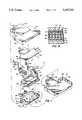
- FIG. 1is an exploded perspective view of an electrical connector in accordance with an embodiment of the invention.
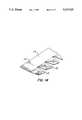
- FIG. 2is a perspective view of an electrical connector in accordance with an embodiment of the invention.
- FIG. 3is a top plan view of the electrical connector of FIG. 2.
- FIG. 4is a side elevation view of the electrical connector of FIG. 2.
- FIG. 5is an end elevation view of a cable receiving end of the electrical connector of FIG. 2.
- FIG. 6is an end elevation view of a connector receiving end of the electrical connector of FIG. 2.
- FIG. 7is a top plan view of an electrical connector in accordance with an embodiment of the invention with portions of a connector housing and a housing cover removed to show the actuation of the latching arms prior to engagement with a complementary electrical connector.
- FIG. 8is a top plan view of the electrical connector of FIG. 7 showing the engagement of the latching arms with a complementary electrical connector.
- FIG. 9is a cross-sectional view of an electrical connector in accordance with an embodiment of the invention showing an electrical shielding member in shielding contact with the connector housing and a connector module.
- FIG. 10is a top plan detail view of an embodiment of a latching arm of an electrical connector in accordance with an embodiment of the invention.
- FIG. 11is a side elevation detail view of the latching arm of FIG. 10.
- FIG. 12is a demonstrative view of an embodiment of the electrical connector in accordance with the invention showing the high separation resistance of the latching arms.
- FIG. 13is a partial view of a prior art connector with a cover removed.
- FIG. 14is a detail view of the distributed tab elements of the electrical shielding member.
- Connector 10comprises a housing 20 and latching arms 50 along each lateral side of the housing 20.
- the housing 20has an upper wall 22 and a lower wall 24.
- the housing 20is preferably formed of die cast zinc.
- the housing 20has lateral side walls 26 integrally joined with the lower wall 24.
- Housing 20has a cable receiving end 28 and a connector receiving end 30.
- the connector receiving end 30has opposing channels 32 formed in side walls 26 for receiving a connector module 34.
- the connector module 34comprises a plastic sleeve 36 for frictionally fitting into channels 32.
- Sleeve 36has a plurality of pin elements 38 which are adapted to be connected to a plurality of wires.
- An electrically conductive barrel element 40surrounds the pin elements 38.
- Cable receiving end 28 of housing 20is adapted to receive and clamp onto coaxial shielded cable having a plurality of wires therein.
- the connector receiving end 30has a greater width than the cable receiving end 28.
- the housing 20, and particularly the upper and lower walls 22 and 24have a width that narrows from the connector receiving end 30 to the cable receiving end 28.
- the lateral side walls 26conform with the changing width of the upper and lower walls 22 and 24.
- Housing 20has four pivot pin receiving apertures 42 formed in four tabs 44 extending laterally from the housing 20.
- Tabs 44are located in the planes of the upper and lower walls 22 and 24. Preferably, tabs 44 extend from the wider portion 45 of the housing 20.
- latching arms 50have engaging ends 52 having hooking tabs 54 for engaging a complementary electrical connector 56, and actuator ends 58 for finger grasping to move the engaging ends 52 of the latching arms 50.
- Pivot pins 60are provided to seat into the pivot pin receiving apertures 42 to permit pivoting of the latching arms 50 around the pivot points 62.
- the pivot pins 60are preferably located between the engaging ends 52 and the actuator ends 58.
- the latching arms 50are generally shaped to conform with the lateral side walls 26, and the actuator ends 58 are located generally adjacent the cable receiving end 28 so that the actuator ends 58 may be finger grasped from the cable receiving end 28 of housing 20. Most preferably, the actuator ends 58 are located closely together so that an operator's fingers can grasp the actuator ends 58 within the width of the electrical connector 10, so that even where multiple connectors 10 are placed closely next to each other in stacks or rows, the latching arms 50 of the connectors 10 can be easily operated to engage or disengage the connector 10 from the complementary electrical connector 56.
- Complementary connector 56has two extending prongs 57. Each prong 57 has a hook element 59 located at one side of the prong 57, at positions selected so that the hook elements 59 can be engaged by the hooking tabs 54 of the latching arms 50.
- spring arms 64are integrally formed with and cut away from the latching arms 50.
- the spring arms 64are connected with the latching arms 50 adjacent the engaging ends 52 and extend therefrom in the direction of the actuator ends 58.
- the spring arms 64comprise a first spring arm segment 66 located in the plane of the latching arm 50 and a second spring arm segment 68 extending inwardly therefrom to bear against the housing 20.
- the spring arms 64have a sufficient length to provide a spring resilience so that the latching arms 50 may be pivoted about the pivot points 62 by finger grasping pressure on the actuator ends 58 to engage or disengage the engaging ends 52 from the complementary electrical connector 56.
- finger grasping pressurecauses the engaging ends 52 to move laterally outwardly to release the engaging ends 52 from the complementary electrical connector 56.
- the latching arms 50comprise a first segment 70 extending straight from the hooking tabs 54 of the engaging end 52, a second segment 72 extending inwardly from the first segment 70 at an angle A of about 135 degrees, a third segment 74 extending inwardly from the second segment 72 at an angle B of about 135 degrees such that the third segment 74 is generally perpendicular to the first segment 70, a fourth segment 76 extending inwardly from the third segment 74 at an angle C of about 95 degrees, and a fifth segment 78 comprising the actuator end 58 extending outwardly from the fourth segment 76 at an angle D of about 5 degrees.
- the spring arms 64extend from the first latching arm segment 70 in a zone adjacent the engaging end 52 to a beginning zone of the second segment 72.
- First spring arm segment 66is located in a plane defined by the first latching arm segment 70, and second spring arm segment 68 extends inwardly from the first spring arm segment 66 at an angle E of about 15 degrees to bear against the housing 20.
- the hooking tabs 54preferably have tab first segments 90 extending from and in the same axis as the first segment 70 of the latching arms 50 and tab second segments 92 extending inwardly and generally perpendicularly from the tab first segments 90.
- the hooking tabs 54are formed by stamping to bend over the tabs 54 to form the segments 90 and 92.
- housing cover 94preferably comprises top and bottom halves 96 and 98 which are adapted to be secured together by interfitting pins 100 and pin receiving apertures 102.
- housing cover 94preferably comprises a larger rectangular segment 104 for covering the housing 20 and the latching arms 50 in the area of the connector receiving end 30, and a smaller rectangular segment 106 for covering the housing 20 and the latching arms 50 in the area of the cable receiving end 28.
- the smaller rectangular segment 106is provided with rectangular apertures 108 for providing finger access to grasp the actuator ends 58 of the latching arms 50.
- a resilient conductive electrical shielding member 110 having a plurality of distributed tab elements 112is preferably provided for electrically connecting the housing 20 and the connector module barrel element 40 to act as a distributed RF shield.
- the electrical shielding member 110preferably comprises an electrically conductive strip 114 affixed to and in electrical contact with the housing 20.
- the tab elements 112extend generally laterally and outwardly away from the strip 114.
- the tab elements 112are generally rectangular elements creased diagonally from opposite corners of the rectangular tabs 112.
- the resilient conductive electrical shielding member 110consists essentially of a beryllium copper alloy.
- the latching arms 50are formed of relatively thick gauge metal, preferably steel having a thickness of about 0.040 inches, to prevent bending or deformation of the engaging ends 52.
- the prongs 57 and hook elements 59 of the complementary connector 56are formed of thick gauge metal of about the same thickness.
- the latching arms 50are very strong, and are capable of retaining the electrical connector 10 to the complementary electrical connector 56 to resist separation forces of at least 50 pounds.
- the strength of the cable connectorwas shown by the following demonstration.
- the electrical connector 10was secured to a complementary electrical connector on a workstation computer 12.
- the computerwas then lifted by the cable 14 onto which the electrical connector 10 was mounted.
- the person performing the demonstrationbegan turning around until centripedal forces caused the computer to extend outwardly from the person.
- the electrical connector 10kept the cable 14 secured to the computer 12.
- Other testshave included yanking, pulling, and twisting of the cable 14.
- the electrical connector 10remains secured to the computer 12. Under high mechanical loads, the computer internal framework and/or casing is more likely to give way before the connector 10 releases.
- the present inventiontherefore provides a novel and useful connector apparatus that is sturdy, yet easy to use. It is to be appreciated that the foregoing is illustrative and not limiting of the invention, and that the practitioner may also develop other embodiments all within the scope of the invention.
Landscapes
- Details Of Connecting Devices For Male And Female Coupling (AREA)
Abstract
Description
Claims (22)
Priority Applications (1)
| Application Number | Priority Date | Filing Date | Title |
|---|---|---|---|
| US07/786,561US5167523A (en) | 1991-11-01 | 1991-11-01 | Electrical connector |
Applications Claiming Priority (1)
| Application Number | Priority Date | Filing Date | Title |
|---|---|---|---|
| US07/786,561US5167523A (en) | 1991-11-01 | 1991-11-01 | Electrical connector |
Publications (1)
| Publication Number | Publication Date |
|---|---|
| US5167523Atrue US5167523A (en) | 1992-12-01 |
Family
ID=25138937
Family Applications (1)
| Application Number | Title | Priority Date | Filing Date |
|---|---|---|---|
| US07/786,561Expired - LifetimeUS5167523A (en) | 1991-11-01 | 1991-11-01 | Electrical connector |
Country Status (1)
| Country | Link |
|---|---|
| US (1) | US5167523A (en) |
Cited By (27)
| Publication number | Priority date | Publication date | Assignee | Title |
|---|---|---|---|---|
| US5435744A (en)* | 1994-05-19 | 1995-07-25 | The Whitaker Corporation | Sliding boot assembly for electrical connector |
| US5716228A (en)* | 1994-04-19 | 1998-02-10 | Chen; John | Computer plug connector fastening mechanism |
| WO1998024152A1 (en)* | 1996-11-27 | 1998-06-04 | The Whitaker Corporation | Interlocking release latching system for electrical connector |
| US5797771A (en)* | 1996-08-16 | 1998-08-25 | U.S. Robotics Mobile Communication Corp. | Cable connector |
| US5941726A (en)* | 1996-11-27 | 1999-08-24 | The Whitaker Corporation | Interlocking release latching system for electrical connector |
| US6149451A (en)* | 1998-06-12 | 2000-11-21 | Atl Technology, Inc. | Cable connector latching device |
| US6203375B1 (en)* | 1999-12-21 | 2001-03-20 | Tekcon Electronics Corporation | Metal shield and cable arrangement for an electric connector |
| US6217364B1 (en)* | 1999-07-09 | 2001-04-17 | Molex Incorporated | Electrical connector assembly with guide pin latching system |
| US6254417B1 (en)* | 2000-07-20 | 2001-07-03 | Acer Communications And Multimedia Inc. | I/O connector for a portable communications device |
| USD449820S1 (en) | 2001-03-19 | 2001-10-30 | Hon Hai Precision Ind. Co., Ltd. | Cable end connector |
| EP1028496A3 (en)* | 1999-01-26 | 2002-01-30 | Molex Incorporated | Electrical connector with locking mechanism and metal spring |
| US6641429B1 (en)* | 2002-07-31 | 2003-11-04 | Hon Hai Precision Ind. Co., Ltd. | Electrical cable assembly |
| US20050182352A1 (en)* | 2004-02-12 | 2005-08-18 | Dimatteo Kristian | Dialysis catheter tip |
| GB2411778A (en)* | 2004-03-02 | 2005-09-07 | Smk Kk | Reinforcing connector using part of shield |
| US20050287860A1 (en)* | 2004-06-23 | 2005-12-29 | Hon Hai Precision Ind Co., Ltd. | Interlocking member for an electrical connector |
| US20060114968A1 (en)* | 2004-12-01 | 2006-06-01 | Harris Corporation Corporation Of The State Of Delaware | Wireless communications device with white gaussian noise generator and related methods |
| US20070021005A1 (en)* | 2002-12-20 | 2007-01-25 | Mitra Niranjan K | Cable connector and method of assembling a cable to such a cable connector |
| US20100240243A1 (en)* | 2009-03-23 | 2010-09-23 | Hon Hai Precision Industry Co., Ltd. | Electrical connector assembly wth improved latching mechanism |
| US7867010B1 (en)* | 2009-10-10 | 2011-01-11 | Hon Hai Precision Ind. Co., Ltd. | Electrical connector having latchs for locking with a complementary connector |
| US20120237288A1 (en)* | 2011-03-15 | 2012-09-20 | Tyco Electronics Corporation | Pluggable modules having latch mechanisms for gripping receptacle assemblies |
| US20130040483A1 (en)* | 2011-08-12 | 2013-02-14 | Hung Viet Ngo | Electrical connector with latch |
| US20130040485A1 (en)* | 2011-08-12 | 2013-02-14 | Hung Viet Ngo | Electrical connector including guidance and latch assembly |
| US10571640B2 (en) | 2018-06-22 | 2020-02-25 | Panduit Corp. | Cassette adapter and method of installation |
| USD886066S1 (en) | 2017-12-06 | 2020-06-02 | Samtec, Inc. | Securement member of electrical connector |
| USD906250S1 (en) | 2015-11-18 | 2020-12-29 | SZ DJI Technology Co., Ltd. | Connector |
| US11171432B2 (en) | 2016-08-15 | 2021-11-09 | Samtec, Inc. | Anti-backout latch for interconnect system |
| US11196195B2 (en) | 2017-04-10 | 2021-12-07 | Samtec, Inc. | Interconnect system having retention features |
Citations (21)
| Publication number | Priority date | Publication date | Assignee | Title |
|---|---|---|---|---|
| US2760174A (en)* | 1954-08-13 | 1956-08-21 | Burtt | Locking mechanism for electrical connectors |
| US3566336A (en)* | 1968-08-30 | 1971-02-23 | Itt | Connector assembly |
| US3828302A (en)* | 1972-09-13 | 1974-08-06 | Bunker Ramo | Electrical connector and mounting means |
| US4367005A (en)* | 1980-11-05 | 1983-01-04 | Amp Incorporated | Strain relief cover |
| US4455058A (en)* | 1982-03-31 | 1984-06-19 | Amp Incorporated | Electrical connector for flat cable |
| US4621885A (en)* | 1985-09-20 | 1986-11-11 | Amp Incorporated | Ribbon cable connector with improved cover latch |
| US4678256A (en)* | 1984-12-10 | 1987-07-07 | Japan Aviation Electronics Industry Limited | Connector |
| US4699438A (en)* | 1985-11-28 | 1987-10-13 | Hirose Electric Co., Ltd. | Locking mechanism for electrical connector |
| US4702542A (en)* | 1986-05-14 | 1987-10-27 | Honeywell Information Systems Inc. | Latch and lock electrical connector housing |
| US4726783A (en)* | 1985-04-04 | 1988-02-23 | Hirose Electric Company, Ltd. | Locking mechanism for connectors |
| US4762505A (en)* | 1987-04-16 | 1988-08-09 | Amp Incorporated | Positive retention connector latch |
| US4772212A (en)* | 1987-05-20 | 1988-09-20 | Amp Incorporated | Electrical connector for shielded cables with shielded conductor pairs |
| US4838812A (en)* | 1987-04-30 | 1989-06-13 | Hirose Electric Co., Ltd. | Shielded electric connector and wire connecting method |
| US4838808A (en)* | 1987-07-17 | 1989-06-13 | Amp Incorporated | Shielded electrical connector and latch mechanism therefor |
| US4838810A (en)* | 1987-04-30 | 1989-06-13 | Hirose Electric Co, Ltd. | Coupling engagement mechanism for electric connector |
| US4889503A (en)* | 1984-01-16 | 1989-12-26 | Stewart Stamping Corporation | Shielded plug and jack connector |
| US4923409A (en)* | 1988-02-12 | 1990-05-08 | Yazaki Corporation | Locking device for connectors |
| US4941849A (en)* | 1986-12-12 | 1990-07-17 | Amp Incorporated | Shielded electrical connector having an insulating cover on the shielding member |
| US4961711A (en)* | 1988-07-15 | 1990-10-09 | Amp Incorporated | Electrical connector |
| US5011424A (en)* | 1989-11-01 | 1991-04-30 | Amp Incorporated | Latch mechanism for electrical connector |
| US5011425A (en)* | 1989-06-06 | 1991-04-30 | E. I. Du Pont De Nemours And Company | Connector assembly with latching means |
- 1991
- 1991-11-01USUS07/786,561patent/US5167523A/ennot_activeExpired - Lifetime
Patent Citations (21)
| Publication number | Priority date | Publication date | Assignee | Title |
|---|---|---|---|---|
| US2760174A (en)* | 1954-08-13 | 1956-08-21 | Burtt | Locking mechanism for electrical connectors |
| US3566336A (en)* | 1968-08-30 | 1971-02-23 | Itt | Connector assembly |
| US3828302A (en)* | 1972-09-13 | 1974-08-06 | Bunker Ramo | Electrical connector and mounting means |
| US4367005A (en)* | 1980-11-05 | 1983-01-04 | Amp Incorporated | Strain relief cover |
| US4455058A (en)* | 1982-03-31 | 1984-06-19 | Amp Incorporated | Electrical connector for flat cable |
| US4889503A (en)* | 1984-01-16 | 1989-12-26 | Stewart Stamping Corporation | Shielded plug and jack connector |
| US4678256A (en)* | 1984-12-10 | 1987-07-07 | Japan Aviation Electronics Industry Limited | Connector |
| US4726783A (en)* | 1985-04-04 | 1988-02-23 | Hirose Electric Company, Ltd. | Locking mechanism for connectors |
| US4621885A (en)* | 1985-09-20 | 1986-11-11 | Amp Incorporated | Ribbon cable connector with improved cover latch |
| US4699438A (en)* | 1985-11-28 | 1987-10-13 | Hirose Electric Co., Ltd. | Locking mechanism for electrical connector |
| US4702542A (en)* | 1986-05-14 | 1987-10-27 | Honeywell Information Systems Inc. | Latch and lock electrical connector housing |
| US4941849A (en)* | 1986-12-12 | 1990-07-17 | Amp Incorporated | Shielded electrical connector having an insulating cover on the shielding member |
| US4762505A (en)* | 1987-04-16 | 1988-08-09 | Amp Incorporated | Positive retention connector latch |
| US4838812A (en)* | 1987-04-30 | 1989-06-13 | Hirose Electric Co., Ltd. | Shielded electric connector and wire connecting method |
| US4838810A (en)* | 1987-04-30 | 1989-06-13 | Hirose Electric Co, Ltd. | Coupling engagement mechanism for electric connector |
| US4772212A (en)* | 1987-05-20 | 1988-09-20 | Amp Incorporated | Electrical connector for shielded cables with shielded conductor pairs |
| US4838808A (en)* | 1987-07-17 | 1989-06-13 | Amp Incorporated | Shielded electrical connector and latch mechanism therefor |
| US4923409A (en)* | 1988-02-12 | 1990-05-08 | Yazaki Corporation | Locking device for connectors |
| US4961711A (en)* | 1988-07-15 | 1990-10-09 | Amp Incorporated | Electrical connector |
| US5011425A (en)* | 1989-06-06 | 1991-04-30 | E. I. Du Pont De Nemours And Company | Connector assembly with latching means |
| US5011424A (en)* | 1989-11-01 | 1991-04-30 | Amp Incorporated | Latch mechanism for electrical connector |
Cited By (42)
| Publication number | Priority date | Publication date | Assignee | Title |
|---|---|---|---|---|
| US5716228A (en)* | 1994-04-19 | 1998-02-10 | Chen; John | Computer plug connector fastening mechanism |
| FR2720197A1 (en)* | 1994-05-19 | 1995-11-24 | Whitaker Corp | Connector for electric cable. |
| US5435744A (en)* | 1994-05-19 | 1995-07-25 | The Whitaker Corporation | Sliding boot assembly for electrical connector |
| US5797771A (en)* | 1996-08-16 | 1998-08-25 | U.S. Robotics Mobile Communication Corp. | Cable connector |
| GB2334830A (en)* | 1996-11-27 | 1999-09-01 | Whitaker Corp | Interlocking release latching system for electrical connector |
| US5941726A (en)* | 1996-11-27 | 1999-08-24 | The Whitaker Corporation | Interlocking release latching system for electrical connector |
| WO1998024152A1 (en)* | 1996-11-27 | 1998-06-04 | The Whitaker Corporation | Interlocking release latching system for electrical connector |
| GB2334830B (en)* | 1996-11-27 | 2001-06-06 | Whitaker Corp | Interlocking release latching system for electrical connector |
| US6149451A (en)* | 1998-06-12 | 2000-11-21 | Atl Technology, Inc. | Cable connector latching device |
| EP1028496A3 (en)* | 1999-01-26 | 2002-01-30 | Molex Incorporated | Electrical connector with locking mechanism and metal spring |
| US6217364B1 (en)* | 1999-07-09 | 2001-04-17 | Molex Incorporated | Electrical connector assembly with guide pin latching system |
| US6203375B1 (en)* | 1999-12-21 | 2001-03-20 | Tekcon Electronics Corporation | Metal shield and cable arrangement for an electric connector |
| US6254417B1 (en)* | 2000-07-20 | 2001-07-03 | Acer Communications And Multimedia Inc. | I/O connector for a portable communications device |
| USD449820S1 (en) | 2001-03-19 | 2001-10-30 | Hon Hai Precision Ind. Co., Ltd. | Cable end connector |
| US6641429B1 (en)* | 2002-07-31 | 2003-11-04 | Hon Hai Precision Ind. Co., Ltd. | Electrical cable assembly |
| US20070021005A1 (en)* | 2002-12-20 | 2007-01-25 | Mitra Niranjan K | Cable connector and method of assembling a cable to such a cable connector |
| US7285017B2 (en)* | 2002-12-20 | 2007-10-23 | Fci | Cable connector and method of assembling a cable to such a cable connector |
| US20050182352A1 (en)* | 2004-02-12 | 2005-08-18 | Dimatteo Kristian | Dialysis catheter tip |
| GB2411778A (en)* | 2004-03-02 | 2005-09-07 | Smk Kk | Reinforcing connector using part of shield |
| US20050287860A1 (en)* | 2004-06-23 | 2005-12-29 | Hon Hai Precision Ind Co., Ltd. | Interlocking member for an electrical connector |
| US7086889B2 (en) | 2004-06-23 | 2006-08-08 | Hon Hai Precision Ind. Co. Ltd. | Interlocking member for an electrical connector |
| US20060114968A1 (en)* | 2004-12-01 | 2006-06-01 | Harris Corporation Corporation Of The State Of Delaware | Wireless communications device with white gaussian noise generator and related methods |
| US20100240243A1 (en)* | 2009-03-23 | 2010-09-23 | Hon Hai Precision Industry Co., Ltd. | Electrical connector assembly wth improved latching mechanism |
| US7892015B2 (en)* | 2009-03-23 | 2011-02-22 | Hon Hai Precision Ind. Co., Ltd. | Electrical connector assembly with improved latching mechanism |
| US7867010B1 (en)* | 2009-10-10 | 2011-01-11 | Hon Hai Precision Ind. Co., Ltd. | Electrical connector having latchs for locking with a complementary connector |
| US8727801B2 (en)* | 2011-03-15 | 2014-05-20 | Tyco Electronics Corporation | Pluggable modules having latch mechanisms for gripping receptacle assemblies |
| US20120237288A1 (en)* | 2011-03-15 | 2012-09-20 | Tyco Electronics Corporation | Pluggable modules having latch mechanisms for gripping receptacle assemblies |
| US20130040485A1 (en)* | 2011-08-12 | 2013-02-14 | Hung Viet Ngo | Electrical connector including guidance and latch assembly |
| US8794991B2 (en)* | 2011-08-12 | 2014-08-05 | Fci Americas Technology Llc | Electrical connector including guidance and latch assembly |
| US8834190B2 (en)* | 2011-08-12 | 2014-09-16 | Fci Americas Technology Llc | Electrical connector with latch |
| US20130040483A1 (en)* | 2011-08-12 | 2013-02-14 | Hung Viet Ngo | Electrical connector with latch |
| USD906250S1 (en) | 2015-11-18 | 2020-12-29 | SZ DJI Technology Co., Ltd. | Connector |
| US11171432B2 (en) | 2016-08-15 | 2021-11-09 | Samtec, Inc. | Anti-backout latch for interconnect system |
| US11735844B2 (en) | 2016-08-15 | 2023-08-22 | Samtec, Inc. | Anti-backout latch for interconnect system |
| US11196195B2 (en) | 2017-04-10 | 2021-12-07 | Samtec, Inc. | Interconnect system having retention features |
| USD960107S1 (en) | 2017-12-06 | 2022-08-09 | Samtec, Inc. | Electrical connector |
| USD924170S1 (en) | 2017-12-06 | 2021-07-06 | Samtec, Inc. | Electrical connector |
| USD886066S1 (en) | 2017-12-06 | 2020-06-02 | Samtec, Inc. | Securement member of electrical connector |
| US11048057B2 (en) | 2018-06-22 | 2021-06-29 | Panduit Corp. | Cassette adapter and method of installation |
| US11624885B2 (en) | 2018-06-22 | 2023-04-11 | Panduit Corp. | Cassette adapter and method of installation |
| US10571640B2 (en) | 2018-06-22 | 2020-02-25 | Panduit Corp. | Cassette adapter and method of installation |
| US12222571B2 (en) | 2018-06-22 | 2025-02-11 | Panduit Corp. | Cassette adapter and method of installation |
Similar Documents
| Publication | Publication Date | Title |
|---|---|---|
| US5167523A (en) | Electrical connector | |
| US5445534A (en) | Double lock male/female type connector | |
| CN1309122C (en) | Structure of interlocked connector | |
| EP1172893B1 (en) | Electrical receptacle terminal and connection structure thereof with pin terminal | |
| US5647754A (en) | Short-circuit connector | |
| US6554646B1 (en) | Electrical connector assembly | |
| US4718866A (en) | Electrical connector shield case and method of making same | |
| EP1311036A2 (en) | Electrical connector | |
| US5273453A (en) | Electrical connector with positive latch | |
| EP0562311A2 (en) | Plug-type multipolar electrical connector | |
| US4124267A (en) | Mounting clip for a connector | |
| CA1266103A (en) | Electrical terminal and method of assembly | |
| JPH04109573A (en) | Electric connector and its method of manufacturing | |
| US4127315A (en) | Cable clamp and hood constructions for use with ribbon connectors | |
| JPH0538547Y2 (en) | ||
| KR950034918A (en) | Electrical table connector | |
| JPH0160908B2 (en) | ||
| US5525072A (en) | Electrical connector assembly for interconnecting a flat cable to a circuit board | |
| US12244094B2 (en) | Poke-in wire connector for power connector assembly | |
| EP0102798B1 (en) | Cable clamp for an electrical connector | |
| US4334728A (en) | Zero insertion force connector clip assembly | |
| US4445742A (en) | Electrical cable connector | |
| CA2571702A1 (en) | Contact for an electrical connector | |
| JP2876146B2 (en) | Receptacle type contact | |
| US4458973A (en) | Connector assembly having improved internal latching system |
Legal Events
| Date | Code | Title | Description |
|---|---|---|---|
| AS | Assignment | Owner name:HARBOR ELECTRONICS, INC. A CORP. OF CONNECTICUT, Free format text:ASSIGNMENT OF ASSIGNORS INTEREST.;ASSIGNORS:CRIMMINS, JAMES;KALLIO, RAYMOND J., JR.;REEL/FRAME:005905/0427 Effective date:19911031 | |
| STCF | Information on status: patent grant | Free format text:PATENTED CASE | |
| AS | Assignment | Owner name:CHEMICAL BANK Free format text:SECURITY INTEREST;ASSIGNOR:HARBOR ELECTRONICS, INC.;REEL/FRAME:006631/0857 Effective date:19930726 | |
| FEPP | Fee payment procedure | Free format text:PAYOR NUMBER ASSIGNED (ORIGINAL EVENT CODE: ASPN); ENTITY STATUS OF PATENT OWNER: LARGE ENTITY | |
| AS | Assignment | Owner name:HARBOR ELECTRONICS, INC., CONNECTICUT Free format text:ASSIGNMENT OF ASSIGNORS INTEREST;ASSIGNOR:HARBOR ELECTRONICS, INC.;REEL/FRAME:007189/0671 Effective date:19940726 | |
| FEPP | Fee payment procedure | Free format text:PAT HLDR NO LONGER CLAIMS SMALL ENT STAT AS SMALL BUSINESS (ORIGINAL EVENT CODE: LSM2); ENTITY STATUS OF PATENT OWNER: LARGE ENTITY | |
| FPAY | Fee payment | Year of fee payment:4 | |
| FPAY | Fee payment | Year of fee payment:8 | |
| FPAY | Fee payment | Year of fee payment:12 | |
| AS | Assignment | Owner name:FCI AMERICAS TECHNOLOGY LLC, NEVADA Free format text:CONVERSION TO LLC;ASSIGNOR:FCI AMERICAS TECHNOLOGY, INC.;REEL/FRAME:026064/0573 Effective date:20090930 Owner name:FCI AMERICAS TECHNOLOGY, INC., NEVADA Free format text:CHANGE OF NAME;ASSIGNOR:BERG TECHNOLOGY, INC.;REEL/FRAME:026064/0565 Effective date:19990611 |