US5167233A - Dilating and imaging apparatus - Google Patents
Dilating and imaging apparatusDownload PDFInfo
- Publication number
- US5167233A US5167233AUS07/638,192US63819291AUS5167233AUS 5167233 AUS5167233 AUS 5167233AUS 63819291 AUS63819291 AUS 63819291AUS 5167233 AUS5167233 AUS 5167233A
- Authority
- US
- United States
- Prior art keywords
- balloon
- imaging device
- catheter
- lumen
- tubing
- Prior art date
- Legal status (The legal status is an assumption and is not a legal conclusion. Google has not performed a legal analysis and makes no representation as to the accuracy of the status listed.)
- Expired - Lifetime
Links
- 238000003384imaging methodMethods0.000titleclaimsabstractdescription131
- 230000000916dilatatory effectEffects0.000titleclaimsabstractdescription34
- 208000031481Pathologic ConstrictionDiseases0.000claimsabstractdescription66
- 230000036262stenosisEffects0.000claimsabstractdescription61
- 208000037804stenosisDiseases0.000claimsabstractdescription61
- 239000012530fluidSubstances0.000claimsabstractdescription48
- 238000011144upstream manufacturingMethods0.000claimsabstractdescription3
- 238000000034methodMethods0.000claimsdescription14
- 210000004204blood vesselAnatomy0.000claimsdescription7
- 239000008280bloodSubstances0.000claimsdescription6
- 210000004369bloodAnatomy0.000claimsdescription6
- 238000004891communicationMethods0.000claimsdescription3
- 230000002093peripheral effectEffects0.000claimsdescription3
- 230000035945sensitivityEffects0.000claims1
- 210000001367arteryAnatomy0.000description9
- 239000003550markerSubstances0.000description8
- 230000008878couplingEffects0.000description7
- 238000010168coupling processMethods0.000description7
- 238000005859coupling reactionMethods0.000description7
- 210000004351coronary vesselAnatomy0.000description5
- 239000000463materialSubstances0.000description5
- 238000002594fluoroscopyMethods0.000description4
- 238000002399angioplastyMethods0.000description3
- 239000000565sealantSubstances0.000description3
- 230000002792vascularEffects0.000description3
- 239000004952PolyamideSubstances0.000description2
- 210000000709aortaAnatomy0.000description2
- 239000002184metalSubstances0.000description2
- 229910052751metalInorganic materials0.000description2
- 229920000052poly(p-xylylene)Polymers0.000description2
- 229920002647polyamidePolymers0.000description2
- 229920000642polymerPolymers0.000description2
- 230000001681protective effectEffects0.000description2
- 125000006850spacer groupChemical group0.000description2
- 238000001356surgical procedureMethods0.000description2
- 239000004593EpoxySubstances0.000description1
- 210000003484anatomyAnatomy0.000description1
- 230000004888barrier functionEffects0.000description1
- 239000011248coating agentSubstances0.000description1
- 238000000576coating methodMethods0.000description1
- 150000001875compoundsChemical class0.000description1
- 239000004020conductorSubstances0.000description1
- 238000007796conventional methodMethods0.000description1
- 238000007887coronary angioplastyMethods0.000description1
- 238000013461designMethods0.000description1
- 230000010339dilationEffects0.000description1
- PCHJSUWPFVWCPO-UHFFFAOYSA-NgoldChemical compound[Au]PCHJSUWPFVWCPO-UHFFFAOYSA-N0.000description1
- 239000010931goldSubstances0.000description1
- 229910052737goldInorganic materials0.000description1
- 238000010438heat treatmentMethods0.000description1
- 230000002452interceptive effectEffects0.000description1
- 230000003902lesionEffects0.000description1
- 238000012986modificationMethods0.000description1
- 230000004048modificationEffects0.000description1
- 239000004033plasticSubstances0.000description1
- 229920003023plasticPolymers0.000description1
- 229920000098polyolefinPolymers0.000description1
- 239000004800polyvinyl chlorideSubstances0.000description1
- 229920000915polyvinyl chloridePolymers0.000description1
- 230000005855radiationEffects0.000description1
- 238000007789sealingMethods0.000description1
- 230000002966stenotic effectEffects0.000description1
- 239000000126substanceSubstances0.000description1
Images


Classifications
- A—HUMAN NECESSITIES
- A61—MEDICAL OR VETERINARY SCIENCE; HYGIENE
- A61M—DEVICES FOR INTRODUCING MEDIA INTO, OR ONTO, THE BODY; DEVICES FOR TRANSDUCING BODY MEDIA OR FOR TAKING MEDIA FROM THE BODY; DEVICES FOR PRODUCING OR ENDING SLEEP OR STUPOR
- A61M25/00—Catheters; Hollow probes
- A61M25/10—Balloon catheters
- A61M25/104—Balloon catheters used for angioplasty
- A—HUMAN NECESSITIES
- A61—MEDICAL OR VETERINARY SCIENCE; HYGIENE
- A61B—DIAGNOSIS; SURGERY; IDENTIFICATION
- A61B8/00—Diagnosis using ultrasonic, sonic or infrasonic waves
- A61B8/12—Diagnosis using ultrasonic, sonic or infrasonic waves in body cavities or body tracts, e.g. by using catheters
- A—HUMAN NECESSITIES
- A61—MEDICAL OR VETERINARY SCIENCE; HYGIENE
- A61B—DIAGNOSIS; SURGERY; IDENTIFICATION
- A61B8/00—Diagnosis using ultrasonic, sonic or infrasonic waves
- A61B8/44—Constructional features of the ultrasonic, sonic or infrasonic diagnostic device
- A61B8/4444—Constructional features of the ultrasonic, sonic or infrasonic diagnostic device related to the probe
- A61B8/445—Details of catheter construction
- A—HUMAN NECESSITIES
- A61—MEDICAL OR VETERINARY SCIENCE; HYGIENE
- A61M—DEVICES FOR INTRODUCING MEDIA INTO, OR ONTO, THE BODY; DEVICES FOR TRANSDUCING BODY MEDIA OR FOR TAKING MEDIA FROM THE BODY; DEVICES FOR PRODUCING OR ENDING SLEEP OR STUPOR
- A61M25/00—Catheters; Hollow probes
- A61M25/10—Balloon catheters
- A61M2025/1043—Balloon catheters with special features or adapted for special applications
- A61M2025/1079—Balloon catheters with special features or adapted for special applications having radio-opaque markers in the region of the balloon
Definitions
- the present inventionrelates generally to percutaneous transluminal coronary angioplasty (PTCA) and ultrasonic imaging, and more particularly to a single apparatus having both capabilities.
- PTCApercutaneous transluminal coronary angioplasty
- Intravascular balloon cathetersthat include ultrasonic imaging devices provide an effective alternative to coronary bypass surgery.
- Transluminal angioplasty surgeryutilizes an elongated, flexible catheter having an inflatable balloon at its distal end that is inserted at an appropriate position in a vascular system of a patient. After the catheter is inserted into the vascular system, its balloon is routed to a stenosis. Once the balloon is properly positioned relative to the stenotic lesion, it is inflated with fluid under relatively high pressure. As the balloon expands, it dilates the stenosis, thus allowing blood to flow more freely.
- a contrast compoundsuch as a substance that is opaque to radiation
- the physicianfirst inserts a guide wire into the occluded vessel. After the guide wire has reached the stenosis or the occluded vessel, a tubular catheter having a lumen for the guide wire is pushed along the guide wire and guided by the guide wire until fluoroscopy reveals that the balloon is located within the stenosis. The balloon is then inflated to dilate the stenosis. When the balloon is deflated and removed from the vessel, blood is able to flow more freely through the enlarged stenosis.
- a contrast compoundsuch as a substance that is opaque to radiation
- fluoroscopyenables the physician to locate the position of the stenosis, it fails to provide the physician with detailed, real-time images of the anatomy causing the stenosis during and after the dilation procedure.
- the limitations of fluoroscopyhas lead to attempts to improve upon imaging of the stenosis being treated.
- One such methoduses two catheters, wherein one catheter has an ultrasonic imaging device at its distal end and the other catheter has the inflatable balloon at its distal end.
- the balloon catheteris first inserted into the vessel along the guide wire, positioned within the stenosis, and the balloon is inflated to dilate the stenosis.
- the balloon catheteris then removed and the imaging catheter is inserted to enable the physician to examine the stenosis and determine if further treatment is needed.
- U.S. Pat. No. 4,917,097 to Proudian et al.also discloses a catheter having both dilating and imaging capabilities, wherein the imaging device is positioned at a distal end of the balloon.
- the capability of the Proudian balloon to enter very small diameter stenosesis limited by the relatively large diameter of the imaging device. In order to optimize these types of catheters, it is important for the balloon to be able to enter even the very narrow stenoses.
- Imaging devicestypically include an imaging array that enables the device only to image an integral (or "slice") of the stenosis immediately adjacent to the periphery of the array. Therefore, the entire balloon catheter must be moved in order for the physician to examine additional integrals of the stenosis.
- a primary object of the present inventionto provide a dilating assembly capable of both dilating a stenosis of a blood vessel with an inflatable balloon and imaging the stenosis with an ultrasonic imaging device, wherein the inclusion of the imaging device on the catheter does not affect the ability of the balloon to achieve a very low profile and be able to enter very narrow stenoses.
- Another object of the present inventionis to provide a dilating assembly capable of both achieving a low profile of very small diameter and dilating a stenosis while simultaneously imaging the entire portion of the stenosis being dilated.
- An additional object of the present inventionis to provide an imaging catheter capable of providing a high quality image.
- the inventiongenerally provides a dilating and imaging apparatus for attaching to and receiving pressurized fluid from a distal end of a catheter.
- the apparatusincludes an inflatable balloon and an imaging device positioned behind an expandable portion of the balloon and upstream of the flow of pressurized fluid into the balloon so as to enable the balloon to deflate and achieve a smaller diameter than that of the imaging device, this aspect enabling the apparatus to enter a stenosis having a smaller diameter than the imaging device.
- the imaging devicecan be maneuvered within the balloon while the balloon is inflated and dilating the stenosis.
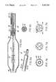
- FIG. 1ais a schematic illustration of a catheter assembly according to the invention utilized for an angioplasty procedure in a coronary artery of a heart;
- FIG. 1bis an enlarged cross-sectional view of a distal end of a dilating apparatus according to the invention positioned within a stenosis as shown in FIG. 1b;
- FIG. 2ais cross-sectional view of the distal end of the dilating apparatus taken along a longitudinal axis of the catheter;
- FIG. 2bis an enlarged cross-sectional view of an imaging device within an inflatable balloon of the dilating apparatus shown FIG. 2a;
- FIG. 3ais a cross-sectional view of a second embodiment of the distal end of the dilating apparatus taken along the longitudinal axis of the catheter;
- FIG. 3bis an enlarged cross-sectional view of an imaging device within an inflatable balloon of the dilating apparatus shown in FIG. 3a;
- FIG. 3cis a cross-sectional view of the imaging device taken along line 3c--3c of FIG. 3b;
- FIG. 4ais a cross-sectional view of a third embodiment of the distal end of the dilating apparatus taken along the longitudinal axis of the catheter;
- FIG. 4bis an enlarged cross-sectional view of an imaging device within an inflatable balloon of the dilating apparatus shown in FIG. 4a;
- FIG. 5is a cross-sectional view of a fourth embodiment of the distal end of the dilating apparatus taken along the longitudinal axis of the catheter;
- FIG. 6ais a cross-sectional view of a fifth embodiment of the distal end of the dilating apparatus taken along the longitudinal axis of the catheter;
- FIG. 6bis an enlarged view of a push wire within the dilating apparatus shown in FIG. 6a wherein a micro-cable is contained within the push wire;
- FIG. 6cis a cross-sectional view of the push wire taken along line 6c--6c of FIG. 6b;
- FIGS. 7a-care cross-sectional views of possible embodiments of the catheter that is connected to the invention, wherein lumens within the catheter are arranged differently in each embodiment.
- FIG. 1aillustrates a dilating and imaging apparatus 10 according to the present invention as it is being utilized in a coronary artery 12 of a heart 14.
- the coronary artery 12contains a buildup of fatty material or plaque 16 that is causing the coronary artery 12 to become occluded or have a stenosis.
- the occluded section or stenosis 16 of the artery 12may be treated by inserting a balloon 18 of the dilating apparatus 10, in a low profile or deflated state, into the artery 12 by using a catheter assembly 20.
- the catheter assembly 20is a three-part assembly, having a guide wire 22, a guide catheter 24 for threading through large arteries such as the aorta 26, and a smaller diameter catheter 28 that fits inside the guide catheter 24.
- the catheter assembly 20includes a tri-arm adapter 30 having a signal processor port 32, a guide wire insert port 34, and an inflation port 36 that is in communication with a fluid lumen in the catheter 28.
- the tri-arm adaptor 30enables a signal processor 38 (that is linked to a video display 40), a guide wire 22, and an inflation source 42 all to be interconnected within the smaller catheter 28 and to communicate with the dilating and imaging apparatus 10.
- the smaller catheter 28is inserted into the larger guide catheter 24 by means of a luer lock connector or angioplasty manifold 43 before entering the heart 14.
- the smaller diameter catheter 28 and the larger diameter catheter 24may be made of a suitable, flexible material such as polyolefin or polyvinylchloride.
- the smaller diameter catheter 28is inserted.
- the guide wire 22is first extended into the artery 12, followed by the smaller catheter 28, which includes the balloon 18 on a distal end of the catheter 28.
- a single dilating and imaging apparatusis provided that is capable of achieving a low profile having a smaller diameter than that of an imaging device located within a proximal sleeve of the balloon.
- Meansare provided for communicating the flow of pressurized fluid past the imaging device before entering an expandable portion of the balloon.
- an imaging device 44is positioned within the proximal sleeve 46 of the balloon 18 in order to enable the balloon 18 to achieve a low profile having a smaller diameter than that of the imaging device 44. This is possible because the imaging device 44 is positioned within the proximal sleeve 46 that is behind an expandable portion of the balloon 18.
- the expandable portion of the balloon 18is that portion of the balloon 18 between the proximal sleeve 46 and the distal sleeve 52.
- the imaging device 44includes a central bore 41 for maintaining a first lumen 39 through the imaging device 44 and into the balloon 18.
- the central bore 41enables the guide wire 22, which is passed through a tubing 50, to pass through the center of the imaging device 44.
- FIG. 1bshows how the deflated balloon 18 is able to follow the guide wire 22 and enter a stenosis 16 having a smaller diameter than the imaging device 44 because the imaging device 44 is positioned in the proximal sleeve 46 of the balloon 18.
- the balloon 18enters the stenosis or occluded artery 16 in a low profile or deflated state. Once the balloon 18 is properly positioned within the stenosis 16, pressurized fluid communicated to the interior of the balloon 18 via the catheter 28 causes the balloon 18 to inflate and dilate the stenosis 16. After the stenosis 16 has been dilated by the inflated balloon 18, the balloon is deflated by withdrawing the pressurized fluid.
- the proximal sleeve 46 of the balloon 18, which contains the imaging device 44,then may be positioned inside the dilated stenosis 16 by further inserting the catheter 28 into the artery 12.
- An imaging array 48 located within the imaging device 44is highly directional and, therefore, the imaging device 44 must be able to enter the dilated stenosis in order to generate a complete image of the dilated stenosis 16.
- FIGS. 2a and 2bare cross-sections of one embodiment of the present invention.
- FIG. 2bis an enlarged cross-sectional view of the proximal sleeve 46 and the imaging device 44 shown in FIG. 2a.
- the tubing 50 having a first lumen 39extends through the interior of the balloon 18.
- the tubing 50runs parallel with a longitudinal axis of the catheter 28.
- a distal sleeve 52 of the balloon 18is hermetically sealed, or joined, to a distal end 54 of the tubing 50, and the proximal sleeve 46 of the balloon 18 is hermetically sealed, or joined, to an outer surface of the smaller diameter catheter 28, thereby sealing off the interior of the balloon 18 from the external environment.
- a proximal end 53 of the tubing 50is connected to a distal end of a guide wire lumen (see FIGS. 7a-c) of the catheter 28.
- the balloon 18may be secured to the tubing 50 with a sealant or by heating the balloon 18 in order to constrict the distal sleeve 52 and the proximal sleeve 46 around the tubing 50 and the catheter 28, respectively.
- the balloon 18is coaxial to and encompasses the tubing 50 which creates a second lumen 56 between an inner wall of the balloon 18 and an outer surface of the tubing 50.
- Means for communicating the flow of pressurized fluid past the imaging device 44are provided by an annular passageway 45 within the second lumen 56.
- the annular passageway 45is formed between a peripheral surface of the imaging device 44 and an inner wall of the proximal sleeve 46 such that the pressurized fluid is in communication with the interior of the balloon 18.
- the imaging device 44is in direct contact with the pressurized fluid, and therefore, should be insulated from the pressurized fluid by a protective sealant.
- One type of protective sealant that may be usedis a thin coating of parylene polymer. Parylene polymer is a product trade name and manufactured by Union Carbide Corporation.
- a fluoroscopically visible cylindrical marker band 58is secured around the tubing 50 at a location within the balloon 18.
- Another marker band 60is located within the imaging device 44.
- the marker bands 58 and 60enable the position of the balloon 18 and the imaging array 44 to be monitored as the catheter 28 is inserted into the vascular system of the patient.
- Additional marker bandsmay be secured to the apparatus 10 in order to monitor specific sections of the apparatus 10.
- an additional marker band(not shown) may be secured to the distal end of the tubing 50 in order to monitor the position of the distal sleeve 52.
- the marker bandsmay be fabricated of gold or other suitable dense metal.
- the marker bandstypically have a wall thickness on the order of 0.003 inches and an internal diameter corresponding to the surface diameter of the tubing 50 to which the marker bands are to be mounted.
- a micro-cable 62that extends through the second lumen 56 back to the proximal end of the catheter 28, interlinks electronics of the imaging device 44 to the signal processor 38 (FIG. 1).
- the micro-cable 62is about 0.017 inches in diameter and has a number of individual insulated conductors.
- the signal processor 38is connected to a video display 40 that displays an image of the stenosis 16 as detected by the imaging array 48.
- the imaging device 44is situated within the proximal sleeve 46 by mounting means.
- the mounting meansmay include securing the imaging device 44 directly to the tubing 50.
- the tubing 50is spliced at a location within the proximal sleeve 46 and a tubing coupling 64, to which the imaging device 44 is secured, is inserted into opposing ends of the slice.
- the tubing coupling 64is more sturdy than the tubing 50 and provides a stronger mounting for the imaging device 44.
- the tubing coupling 64can be constructed of a sturdy material such as polyamide.
- FIGS. 3a-3cillustrate another embodiment of the present invention, wherein another communicating means and mounting means are provided.
- FIG. 3ashows a cross-sectional view of the apparatus 10 and
- FIG. 3bshows an enlarged view of the proximal sleeve 46 which contains the imaging device 44.
- the communicating meansinclude both an annular passageway 45 and a plurality of central passageways 66.
- the plurality of central passageways 66are located between an outer surface 67 of the tubing 50 and an inner surface 69 of the central bore 41 (FIG. 3c).
- FIG. 3cshows a cross-sectional view of the imaging device 44 shown in and taken along line 3c--3c of FIG. 3b.
- the plurality of central passageways 66run parallel with the tubing 50 and are positioned between the inner surface 69 of the central bore 41 and the outer surface 67 of the tubing 50.
- the mounting meansinclude mounting segments 68 of the central bore 41 which are secured to portions of the outer surface of the tubing 50. This embodiment increases the flow rate of the pressurized fluid to and from the balloon 18, but it is more difficult and costly to produce.
- FIGS. 4a and 4billustrate another embodiment of the invention wherein the imaging array 48 is exposed directly to blood in the artery.
- the featureenables the apparatus 10 to provide a high quality image because there is no attenuation or reflection (echo) resulting from a barrier between the imaging array 48 and the inner walls of the artery 12, except for the blood which provides a medium for ultrasonic waves generated by the imaging array 48.
- this configurationalso positions the imaging device 44 behind the expandable portion of the balloon 18.
- the imaging device 44includes a carrier extension 70 that is attached to the imaging device 44.
- the carrier extensionmay be formed from a rigid plastic, epoxy, metal or suitable material.
- the proximal sleeveis spliced to create an anterior end 72 and a posterior end 74.
- Mounting meansare provided by securing the carrier extension 70 to the anterior end 72 and securing the posterior end 74 to the imaging device 44.
- Communicating meansare provided by a gap 76 between the inner wall 47 of the central bore 41 and the outer surface of the tubing 50.
- a tubing coupling 64may be used to provide a section of the tubing 50 that is smaller in diameter and has thinner walls. This embodiment allows for the gap 76 to exist between the outer surface of the tubing coupling 64 and the inner wall 47 of the central bore 41.
- FIG. 5illustrates another embodiment of the present invention wherein the proximal sleeve 46 includes a lumen attachment 78 located between the imaging device 44 and the expandable portion of the balloon 18.
- the lumen attachmentis a ring-shaped spacer that serves to position the proximal sleeve 46 at a radially spaced position from the tubing 50.
- the ring-shaped spaceris made of any suitable rigid material.
- An inner wall of the attachment 78is mounted to the outer surface of the tubing coupling 64, and an outer surface of the attachment 78 is mounted to the inner wall of the proximal sleeve 46.
- the lumen attachment 78also includes flow channels 80 that enable the pressurized fluid to pass through the lumen attachment 80.
- the communicating meansinclude a gap 82 similar to gap 76 of FIG. 4a.
- the flow channels 80 in combination with the gap 82provide means for communicating the pressurized fluid to the balloon 18.
- Means for mounting the imaging device 44are provided by securing the outer periphery of the imaging device 44 to the inner wall of the proximal sleeve 46.
- This embodimentprovides additional mechanical support to the proximal sleeve 46.
- the prior embodiment illustrated in FIG. 2aplaces a great deal of operational forces on the proximal sleeve 46.
- the lumen attachment 78 in this embodimentprovides additional support to the proximal sleeve 46 in order to lessen the operational forces on the proximal sleeve 46.
- FIG. 6aillustrates another important aspect of the present invention, wherein the imaging device 44 is slidably mounted to the tubing 50 so as to enable the imaging device 44 to generate a complete image of the stenosis 16 while the inflated balloon 18 simultaneously dilates the stenosis 16 in this embodiment.
- a push wire 84is attached to the imaging device 44 and extends back through the second lumen 56 to the proximal end of the catheter 28.
- the push wire 84is a flexible hypotube (thin-walled tube) wherein a micro-cable 63 is located inside the push wire 84.
- the diameter of the push wire 84is approximately 0.014 inches.
- the push wire 84enables a surgeon to remotely maneuver the imaging device 44 within the balloon 18 while the balloon 18 is inflated.
- the surgeoncan image the entire portion of the stenosis 16 being dilated by the inflated balloon 18 by sliding the imaging device 44 along the entire length of the tubing 50 that is located within the expandable portion of the balloon 18.
- a portion of the tubing 50 that is located within the proximal sleeve 46 and the expandable portion of the balloon 18is preferably be replaced with a sturdier micro-tube 86 in order to enable the imaging device 44 to slide more easily within the balloon 18.
- the micro-tube 86is similar to the tubing coupling 64 because it is inserted in opposing ends of a splice in the tubing 50.
- the micro-tube 86may also be made from polyamide.
- the imaging device 44is initially positioned within the proximal sleeve 46 when the balloon 18 is deflated and being inserted into the stenosis 16. Positioning the device 44 within the proximal sleeve 46 enables the balloon 18 to achieve a low profile that is not restricted by the diameter of the imaging device 44. After the balloon 18 is inflated with pressurized fluid, the surgeon then uses the push wire 84 to push the imaging device out of the proximal sleeve 46 and into the expandable portion of the balloon 18. By sliding the imaging device 44 along the micro-tube 86, the surgeon is able to image all sections of the stenosis 16 which are being dilated by the inflated balloon.
- the surgeonmay then deflate the balloon 18 and image the stenosis 16 in order to determine whether the stenosis 16 maintains a dilated form after the balloon 18 is removed.
- the imaging device 44is first maneuvered back into the proximal sleeve 46 before deflating the balloon 18.
- the stenosis 16is imaged by inserting the proximal sleeve 46, which contains the imaging device 44, further into the stenosis 16.
- FIG. 7aillustrates a coaxial lumen arrangement wherein the pressurized fluid, micro-cable 62 (or push wire 84) may pass through the outer lumen 90 and the guide wire 22 may pass through the inner lumen 92.
- FIG. 7billustrates a side-by-side lumen arrangement wherein the guide wire 22 may pass through lumen 94, and the pressurized fluid and micro-cable 62 may pass through lumen 96.
- FIG. 7aillustrates a coaxial lumen arrangement wherein the pressurized fluid, micro-cable 62 (or push
- FIG. 7cdiscloses a tri-lumen arrangement wherein the guide wire 22 may pass through lumen 98, the pressurized fluid may pass through lumen 100, and the micro-cable 62 (or push wire 84) may pass through lumen 102.
- the apparatus of the present inventionis simply secured to the distal end of the catheter in a conventional manner so that the guide wire 22, pressurized fluid, and micro-cable 62 (or push wire 84) communicate correctly with the apparatus.
- these illustrated lumensare only exemplary of the different catheters that may be used with this invention and are not intended to limit the invention to only those catheters illustrated herein.
Landscapes
- Health & Medical Sciences (AREA)
- Life Sciences & Earth Sciences (AREA)
- Heart & Thoracic Surgery (AREA)
- Animal Behavior & Ethology (AREA)
- Biophysics (AREA)
- Veterinary Medicine (AREA)
- Public Health (AREA)
- General Health & Medical Sciences (AREA)
- Engineering & Computer Science (AREA)
- Biomedical Technology (AREA)
- Surgery (AREA)
- Molecular Biology (AREA)
- Physics & Mathematics (AREA)
- Medical Informatics (AREA)
- Radiology & Medical Imaging (AREA)
- Pathology (AREA)
- Nuclear Medicine, Radiotherapy & Molecular Imaging (AREA)
- Vascular Medicine (AREA)
- Child & Adolescent Psychology (AREA)
- Pulmonology (AREA)
- Anesthesiology (AREA)
- Hematology (AREA)
- Media Introduction/Drainage Providing Device (AREA)
- Ultra Sonic Daignosis Equipment (AREA)
Abstract
Description
Claims (15)
Priority Applications (6)
| Application Number | Priority Date | Filing Date | Title |
|---|---|---|---|
| US07/638,192US5167233A (en) | 1991-01-07 | 1991-01-07 | Dilating and imaging apparatus |
| JP4504415AJP2552421B2 (en) | 1991-01-07 | 1991-12-31 | Expansion / imaging device |
| DE69122380TDE69122380T2 (en) | 1991-01-07 | 1991-12-31 | DEVICE FOR DILATION AND FOR IMAGE GENERATION |
| EP92904268AEP0519060B1 (en) | 1991-01-07 | 1991-12-31 | Dilating and imaging apparatus |
| PCT/US1991/009821WO1992011809A1 (en) | 1991-01-07 | 1991-12-31 | Dilating and imaging apparatus |
| CA002076378ACA2076378C (en) | 1991-01-07 | 1991-12-31 | Dilating and imaging apparatus |
Applications Claiming Priority (1)
| Application Number | Priority Date | Filing Date | Title |
|---|---|---|---|
| US07/638,192US5167233A (en) | 1991-01-07 | 1991-01-07 | Dilating and imaging apparatus |
Publications (1)
| Publication Number | Publication Date |
|---|---|
| US5167233Atrue US5167233A (en) | 1992-12-01 |
Family
ID=24559021
Family Applications (1)
| Application Number | Title | Priority Date | Filing Date |
|---|---|---|---|
| US07/638,192Expired - LifetimeUS5167233A (en) | 1991-01-07 | 1991-01-07 | Dilating and imaging apparatus |
Country Status (6)
| Country | Link |
|---|---|
| US (1) | US5167233A (en) |
| EP (1) | EP0519060B1 (en) |
| JP (1) | JP2552421B2 (en) |
| CA (1) | CA2076378C (en) |
| DE (1) | DE69122380T2 (en) |
| WO (1) | WO1992011809A1 (en) |
Cited By (168)
| Publication number | Priority date | Publication date | Assignee | Title |
|---|---|---|---|---|
| US5368037A (en)* | 1993-02-01 | 1994-11-29 | Endosonics Corporation | Ultrasound catheter |
| US5379772A (en)* | 1993-09-14 | 1995-01-10 | Intelliwire, Inc. | Flexible elongate device having forward looking ultrasonic imaging |
| US5411016A (en)* | 1994-02-22 | 1995-05-02 | Scimed Life Systems, Inc. | Intravascular balloon catheter for use in combination with an angioscope |
| WO1995029633A1 (en) | 1994-04-28 | 1995-11-09 | Endosonics Corporation | Ultrasonic apparatus and method for intravascular imaging |
| US5548564A (en)* | 1992-10-16 | 1996-08-20 | Duke University | Multi-layer composite ultrasonic transducer arrays |
| EP0707501A4 (en)* | 1993-07-02 | 1997-01-22 | Ronald J Solar | Rapid withdrawal catheter |
| WO1997023865A1 (en)* | 1995-12-26 | 1997-07-03 | Endosonics Corporation | A high resolution intravascular ultrasound transducer assembly having a flexible substrate |
| WO1998011823A1 (en) | 1996-09-20 | 1998-03-26 | Cardiovascular Imaging Systems, Inc. | Three-dimensional intraluminal ultrasound image reconstruction |
| US5740808A (en)* | 1996-10-28 | 1998-04-21 | Ep Technologies, Inc | Systems and methods for guilding diagnostic or therapeutic devices in interior tissue regions |
| US5744898A (en)* | 1992-05-14 | 1998-04-28 | Duke University | Ultrasound transducer array with transmitter/receiver integrated circuitry |
| EP0754074A4 (en)* | 1994-04-01 | 1998-05-06 | Localmed Inc | Method and apparatus for performing multiple procedures |
| EP0853919A2 (en) | 1997-01-08 | 1998-07-22 | Endosonics Corporation | A high resolution intravascular ultrasound transducer assembly having a flexible substrate and method for manufacture thereof |
| EP0871043A2 (en) | 1997-04-08 | 1998-10-14 | EndoSonics Corporation | A method and apparatus for creating a color blood flow image based upon ultrasonic echo signals received by an intravascular ultrasound imaging probe |
| US5853368A (en)* | 1996-12-23 | 1998-12-29 | Hewlett-Packard Company | Ultrasound imaging catheter having an independently-controllable treatment structure |
| US5876426A (en)* | 1996-06-13 | 1999-03-02 | Scimed Life Systems, Inc. | System and method of providing a blood-free interface for intravascular light delivery |
| EP0920883A1 (en) | 1997-12-09 | 1999-06-09 | EndoSonics Corporation | Modular imaging/treatment catheter assembly and method |
| US5967984A (en)* | 1995-06-30 | 1999-10-19 | Boston Scientific Corporation | Ultrasound imaging catheter with a cutting element |
| US6029671A (en)* | 1991-07-16 | 2000-02-29 | Heartport, Inc. | System and methods for performing endovascular procedures |
| US6036650A (en)* | 1998-09-15 | 2000-03-14 | Endosonics Corporation | Ultrasonic imaging system and method with ringdown reduction |
| US6159165A (en)* | 1997-12-05 | 2000-12-12 | Micrus Corporation | Three dimensional spherical micro-coils manufactured from radiopaque nickel-titanium microstrand |
| US6168570B1 (en) | 1997-12-05 | 2001-01-02 | Micrus Corporation | Micro-strand cable with enhanced radiopacity |
| US6241691B1 (en) | 1997-12-05 | 2001-06-05 | Micrus Corporation | Coated superelastic stent |
| US6263229B1 (en) | 1998-11-13 | 2001-07-17 | Johns Hopkins University School Of Medicine | Miniature magnetic resonance catheter coils and related methods |
| US6391052B2 (en) | 1994-04-29 | 2002-05-21 | Scimed Life Systems, Inc. | Stent with collagen |
| US6549800B1 (en) | 1996-04-25 | 2003-04-15 | Johns Hopkins Unversity School Of Medicine | Methods for in vivo magnetic resonance imaging |
| US6606513B2 (en) | 2000-02-01 | 2003-08-12 | Surgi-Vision, Inc. | Magnetic resonance imaging transseptal needle antenna |
| US6628980B2 (en) | 2000-03-24 | 2003-09-30 | Surgi-Vision, Inc. | Apparatus, systems, and methods for in vivo magnetic resonance imaging |
| US6635054B2 (en) | 2000-07-13 | 2003-10-21 | Transurgical, Inc. | Thermal treatment methods and apparatus with focused energy application |
| US6641540B2 (en) | 2000-12-01 | 2003-11-04 | The Cleveland Clinic Foundation | Miniature ultrasound transducer |
| US6675033B1 (en) | 1999-04-15 | 2004-01-06 | Johns Hopkins University School Of Medicine | Magnetic resonance imaging guidewire probe |
| US6697667B1 (en) | 2001-05-31 | 2004-02-24 | Advanced Cardiovascular Systems, Inc. | Apparatus and method for locating coronary sinus |
| US6701176B1 (en) | 1998-11-04 | 2004-03-02 | Johns Hopkins University School Of Medicine | Magnetic-resonance-guided imaging, electrophysiology, and ablation |
| US20040054287A1 (en)* | 2002-08-29 | 2004-03-18 | Stephens Douglas Neil | Ultrasonic imaging devices and methods of fabrication |
| US6712767B2 (en) | 2002-08-29 | 2004-03-30 | Volcano Therapeutics, Inc. | Ultrasonic imaging devices and methods of fabrication |
| US6716178B1 (en) | 2001-05-31 | 2004-04-06 | Advanced Cardiovascular Systems, Inc. | Apparatus and method for performing thermal and laser doppler velocimetry measurements |
| US20040067000A1 (en)* | 2002-10-07 | 2004-04-08 | Bates Kenneth N. | Systems and methods for minimally-invasive optical-acoustic imaging |
| US20040082844A1 (en)* | 1998-03-05 | 2004-04-29 | Vardi Gil M. | Optical-acoustic imaging device |
| US20040260182A1 (en)* | 2003-06-23 | 2004-12-23 | Zuluaga Andres F. | Intraluminal spectroscope with wall contacting probe |
| US20050075574A1 (en)* | 2003-09-22 | 2005-04-07 | Simon Furnish | Devices for vulnerable plaque detection |
| US6879851B2 (en) | 2001-06-07 | 2005-04-12 | Lightlab Imaging, Llc | Fiber optic endoscopic gastrointestinal probe |
| US6898454B2 (en) | 1996-04-25 | 2005-05-24 | The Johns Hopkins University | Systems and methods for evaluating the urethra and the periurethral tissues |
| US20050222596A1 (en)* | 2004-03-31 | 2005-10-06 | Siemens Aktiengesellschaft | Device for implementing a cutting balloon intervention with IVUS monitoring |
| US20070016071A1 (en)* | 1993-02-01 | 2007-01-18 | Volcano Corporation | Ultrasound transducer assembly |
| US20070076212A1 (en)* | 2005-09-30 | 2007-04-05 | Zuluaga Andres F | Detecting vulnerable plaque |
| US20070116408A1 (en)* | 2005-11-22 | 2007-05-24 | Eberle Michael J | Optical imaging probe connector |
| US7236816B2 (en) | 1996-04-25 | 2007-06-26 | Johns Hopkins University | Biopsy and sampling needle antennas for magnetic resonance imaging-guided biopsies |
| US7329223B1 (en) | 2001-05-31 | 2008-02-12 | Abbott Cardiovascular Systems Inc. | Catheter with optical fiber sensor |
| US20090054922A1 (en)* | 2007-08-23 | 2009-02-26 | Broker Harshal S | Apparatus and Method for the Intravascular Control of Trauma |
| US7532920B1 (en) | 2001-05-31 | 2009-05-12 | Advanced Cardiovascular Systems, Inc. | Guidewire with optical fiber |
| US7540846B2 (en) | 2000-07-13 | 2009-06-02 | Prorhythm, Inc. | Energy application with inflatable annular lens |
| US20090143702A1 (en)* | 2001-01-26 | 2009-06-04 | Lake Region Manufacturing, Inc. | Non-metallic guide wire |
| WO2009129438A1 (en)* | 2008-04-17 | 2009-10-22 | Boston Scientific Scimed, Inc | Intravascular ultrasound imaging systems with sealed catheters filled with an acoustically-favorable medium and methods of making and using |
| US20100023095A1 (en)* | 2001-04-13 | 2010-01-28 | Greatbatch Ltd. | Transient voltage/current protection system for electronic circuits associated with implanted leads |
| US20100191306A1 (en)* | 2006-01-25 | 2010-07-29 | Greatbatch Ltd. | Transient voltage suppression circuit for an implanted rfid chip |
| US20100198312A1 (en)* | 2001-04-13 | 2010-08-05 | Greatbatch Ltd. | Emi filter employing a capacitor and an inductor tank circuit having optimum component values |
| US20100241206A1 (en)* | 2009-03-19 | 2010-09-23 | Greatbatch Ltd. | Emi shielded conduit assembly for an active implantable medical device |
| US7837676B2 (en) | 2003-02-20 | 2010-11-23 | Recor Medical, Inc. | Cardiac ablation devices |
| US7844319B2 (en) | 1998-11-04 | 2010-11-30 | Susil Robert C | Systems and methods for magnetic-resonance-guided interventional procedures |
| US7848788B2 (en) | 1999-04-15 | 2010-12-07 | The Johns Hopkins University | Magnetic resonance imaging probe |
| US20100312095A1 (en)* | 2009-06-08 | 2010-12-09 | Jenkins Kimble L | Mri-guided surgical systems with proximity alerts |
| USRE42856E1 (en) | 2002-05-29 | 2011-10-18 | MRI Interventions, Inc. | Magnetic resonance probes |
| US8219208B2 (en) | 2001-04-13 | 2012-07-10 | Greatbatch Ltd. | Frequency selective passive component networks for active implantable medical devices utilizing an energy dissipating surface |
| US8275466B2 (en) | 2006-06-08 | 2012-09-25 | Greatbatch Ltd. | Band stop filter employing a capacitor and an inductor tank circuit to enhance MRI compatibility of active medical devices |
| US8369930B2 (en) | 2009-06-16 | 2013-02-05 | MRI Interventions, Inc. | MRI-guided devices and MRI-guided interventional systems that can track and generate dynamic visualizations of the devices in near real time |
| US8447414B2 (en) | 2008-12-17 | 2013-05-21 | Greatbatch Ltd. | Switched safety protection circuit for an AIMD system during exposure to high power electromagnetic fields |
| US8457760B2 (en) | 2001-04-13 | 2013-06-04 | Greatbatch Ltd. | Switched diverter circuits for minimizing heating of an implanted lead and/or providing EMI protection in a high power electromagnetic field environment |
| US8509913B2 (en) | 2001-04-13 | 2013-08-13 | Greatbatch Ltd. | Switched diverter circuits for minimizing heating of an implanted lead and/or providing EMI protection in a high power electromagnetic field environment |
| US8560048B2 (en) | 2008-10-02 | 2013-10-15 | Vascular Imaging Corporation | Optical ultrasound receiver |
| WO2014031922A1 (en) | 2012-08-23 | 2014-02-27 | Volcano Corporation | Device, system, and method for anatomical lesion length estimation |
| WO2014100579A1 (en) | 2012-12-21 | 2014-06-26 | David Anderson | Functional gain measurement technique and representation |
| WO2014113188A2 (en) | 2012-12-20 | 2014-07-24 | Jeremy Stigall | Locating intravascular images |
| US8882763B2 (en) | 2010-01-12 | 2014-11-11 | Greatbatch Ltd. | Patient attached bonding strap for energy dissipation from a probe or a catheter during magnetic resonance imaging |
| US8903505B2 (en) | 2006-06-08 | 2014-12-02 | Greatbatch Ltd. | Implantable lead bandstop filter employing an inductive coil with parasitic capacitance to enhance MRI compatibility of active medical devices |
| US8974445B2 (en) | 2009-01-09 | 2015-03-10 | Recor Medical, Inc. | Methods and apparatus for treatment of cardiac valve insufficiency |
| US8989870B2 (en) | 2001-04-13 | 2015-03-24 | Greatbatch Ltd. | Tuned energy balanced system for minimizing heating and/or to provide EMI protection of implanted leads in a high power electromagnetic field environment |
| WO2015106188A1 (en) | 2014-01-10 | 2015-07-16 | Volcano Corporation | Detecting endoleaks associated with aneurysm repair |
| WO2015106197A2 (en) | 2014-01-10 | 2015-07-16 | Volcano Corporation | Detecting endoleaks associated with aneurysm repair |
| WO2015108984A1 (en) | 2014-01-14 | 2015-07-23 | Volcano Corporation | Catheter assembly for vascular access site creation |
| WO2015108942A1 (en) | 2014-01-14 | 2015-07-23 | Volcano Corporation | Vascular access evaluation and treatment |
| WO2015108941A1 (en) | 2014-01-14 | 2015-07-23 | Volcano Corporation | Devices and methods for forming vascular access |
| WO2015108973A1 (en) | 2014-01-14 | 2015-07-23 | Volcano Corporation | Methods and systems for clearing thrombus from a vascular access site |
| US9108066B2 (en) | 2008-03-20 | 2015-08-18 | Greatbatch Ltd. | Low impedance oxide resistant grounded capacitor for an AIMD |
| WO2015156945A1 (en) | 2014-04-11 | 2015-10-15 | Jeremy Stigall | Imaging and treatment device |
| US9164084B2 (en) | 2012-01-31 | 2015-10-20 | Purdue Research Foundation | Methods for determining aggressiveness of a cancer and treatment thereof |
| US20150359433A1 (en)* | 2014-06-12 | 2015-12-17 | Volcano Corporation | Image guided therapeutic catheter with drug eluting balloon |
| WO2016009337A2 (en) | 2014-07-15 | 2016-01-21 | Koninklijke Philips N.V. | Devices and methods for intrahepatic shunts |
| US9242090B2 (en) | 2001-04-13 | 2016-01-26 | MRI Interventions Inc. | MRI compatible medical leads |
| US9248283B2 (en) | 2001-04-13 | 2016-02-02 | Greatbatch Ltd. | Band stop filter comprising an inductive component disposed in a lead wire in series with an electrode |
| WO2016027198A1 (en) | 2014-08-21 | 2016-02-25 | Koninklijke Philips N.V. | Device and methods for crossing occlusions |
| US9286673B2 (en) | 2012-10-05 | 2016-03-15 | Volcano Corporation | Systems for correcting distortions in a medical image and methods of use thereof |
| US9292918B2 (en) | 2012-10-05 | 2016-03-22 | Volcano Corporation | Methods and systems for transforming luminal images |
| US9295828B2 (en) | 2001-04-13 | 2016-03-29 | Greatbatch Ltd. | Self-resonant inductor wound portion of an implantable lead for enhanced MRI compatibility of active implantable medical devices |
| US9301687B2 (en) | 2013-03-13 | 2016-04-05 | Volcano Corporation | System and method for OCT depth calibration |
| US9307926B2 (en) | 2012-10-05 | 2016-04-12 | Volcano Corporation | Automatic stent detection |
| US9324141B2 (en) | 2012-10-05 | 2016-04-26 | Volcano Corporation | Removal of A-scan streaking artifact |
| US9360630B2 (en) | 2011-08-31 | 2016-06-07 | Volcano Corporation | Optical-electrical rotary joint and methods of use |
| US9367965B2 (en) | 2012-10-05 | 2016-06-14 | Volcano Corporation | Systems and methods for generating images of tissue |
| US9383263B2 (en) | 2012-12-21 | 2016-07-05 | Volcano Corporation | Systems and methods for narrowing a wavelength emission of light |
| WO2016132241A1 (en) | 2015-02-20 | 2016-08-25 | Koninklijke Philips N.V. | Atherectomy apparatus with imaging |
| US9427596B2 (en) | 2013-01-16 | 2016-08-30 | Greatbatch Ltd. | Low impedance oxide resistant grounded capacitor for an AIMD |
| US9478940B2 (en) | 2012-10-05 | 2016-10-25 | Volcano Corporation | Systems and methods for amplifying light |
| US9486143B2 (en) | 2012-12-21 | 2016-11-08 | Volcano Corporation | Intravascular forward imaging device |
| US9533123B2 (en) | 2008-10-31 | 2017-01-03 | Vascular Imaging Corporation | Optical imaging probe connector method by deforming a cross section and cutting at an oblique angle |
| US9596993B2 (en) | 2007-07-12 | 2017-03-21 | Volcano Corporation | Automatic calibration systems and methods of use |
| US9612105B2 (en) | 2012-12-21 | 2017-04-04 | Volcano Corporation | Polarization sensitive optical coherence tomography system |
| US9622706B2 (en) | 2007-07-12 | 2017-04-18 | Volcano Corporation | Catheter for in vivo imaging |
| US9700372B2 (en) | 2002-07-01 | 2017-07-11 | Recor Medical, Inc. | Intraluminal methods of ablating nerve tissue |
| US9709379B2 (en) | 2012-12-20 | 2017-07-18 | Volcano Corporation | Optical coherence tomography system that is reconfigurable between different imaging modes |
| US9770172B2 (en) | 2013-03-07 | 2017-09-26 | Volcano Corporation | Multimodal segmentation in intravascular images |
| US9829766B2 (en) | 2009-02-17 | 2017-11-28 | Analog Devices, Inc. | Electro-optic beam deflector device |
| US9858668B2 (en) | 2012-10-05 | 2018-01-02 | Volcano Corporation | Guidewire artifact removal in images |
| US9867530B2 (en) | 2006-08-14 | 2018-01-16 | Volcano Corporation | Telescopic side port catheter device with imaging system and method for accessing side branch occlusions |
| USRE46699E1 (en) | 2013-01-16 | 2018-02-06 | Greatbatch Ltd. | Low impedance oxide resistant grounded capacitor for an AIMD |
| US9931514B2 (en) | 2013-06-30 | 2018-04-03 | Greatbatch Ltd. | Low impedance oxide resistant grounded capacitor for an AIMD |
| US9936881B2 (en) | 2012-10-04 | 2018-04-10 | Vascular Imaging Corporation | Polarization scrambling for intra-body fiber optic sensor |
| US10058284B2 (en) | 2012-12-21 | 2018-08-28 | Volcano Corporation | Simultaneous imaging, monitoring, and therapy |
| US10070827B2 (en) | 2012-10-05 | 2018-09-11 | Volcano Corporation | Automatic image playback |
| US10080889B2 (en) | 2009-03-19 | 2018-09-25 | Greatbatch Ltd. | Low inductance and low resistance hermetically sealed filtered feedthrough for an AIMD |
| US10166003B2 (en) | 2012-12-21 | 2019-01-01 | Volcano Corporation | Ultrasound imaging with variable line density |
| US10175421B2 (en) | 2013-03-14 | 2019-01-08 | Vascular Imaging Corporation | Optical fiber ribbon imaging guidewire and methods |
| US10191220B2 (en) | 2012-12-21 | 2019-01-29 | Volcano Corporation | Power-efficient optical circuit |
| US10219887B2 (en) | 2013-03-14 | 2019-03-05 | Volcano Corporation | Filters with echogenic characteristics |
| US10219780B2 (en) | 2007-07-12 | 2019-03-05 | Volcano Corporation | OCT-IVUS catheter for concurrent luminal imaging |
| US10226597B2 (en) | 2013-03-07 | 2019-03-12 | Volcano Corporation | Guidewire with centering mechanism |
| US10238367B2 (en) | 2012-12-13 | 2019-03-26 | Volcano Corporation | Devices, systems, and methods for targeted cannulation |
| US10251606B2 (en) | 2014-01-14 | 2019-04-09 | Volcano Corporation | Systems and methods for evaluating hemodialysis arteriovenous fistula maturation |
| US10258240B1 (en) | 2014-11-24 | 2019-04-16 | Vascular Imaging Corporation | Optical fiber pressure sensor |
| US10292677B2 (en) | 2013-03-14 | 2019-05-21 | Volcano Corporation | Endoluminal filter having enhanced echogenic properties |
| US10332228B2 (en) | 2012-12-21 | 2019-06-25 | Volcano Corporation | System and method for graphical processing of medical data |
| US10327645B2 (en) | 2013-10-04 | 2019-06-25 | Vascular Imaging Corporation | Imaging techniques using an imaging guidewire |
| US10350421B2 (en) | 2013-06-30 | 2019-07-16 | Greatbatch Ltd. | Metallurgically bonded gold pocket pad for grounding an EMI filter to a hermetic terminal for an active implantable medical device |
| US10413317B2 (en) | 2012-12-21 | 2019-09-17 | Volcano Corporation | System and method for catheter steering and operation |
| US10420530B2 (en) | 2012-12-21 | 2019-09-24 | Volcano Corporation | System and method for multipath processing of image signals |
| US10426590B2 (en) | 2013-03-14 | 2019-10-01 | Volcano Corporation | Filters with echogenic characteristics |
| US10499937B2 (en) | 2006-05-19 | 2019-12-10 | Recor Medical, Inc. | Ablation device with optimized input power profile and method of using the same |
| US10506934B2 (en) | 2012-05-25 | 2019-12-17 | Phyzhon Health Inc. | Optical fiber pressure sensor |
| WO2020002179A1 (en) | 2018-06-28 | 2020-01-02 | Koninklijke Philips N.V. | External targeted delivery of active therapeutic agents |
| WO2020002177A1 (en) | 2018-06-28 | 2020-01-02 | Koninklijke Philips N.V. | Internal ultrasound assisted local therapeutic delivery |
| US10537255B2 (en) | 2013-11-21 | 2020-01-21 | Phyzhon Health Inc. | Optical fiber pressure sensor |
| US10559409B2 (en) | 2017-01-06 | 2020-02-11 | Greatbatch Ltd. | Process for manufacturing a leadless feedthrough for an active implantable medical device |
| US10561837B2 (en) | 2011-03-01 | 2020-02-18 | Greatbatch Ltd. | Low equivalent series resistance RF filter for an active implantable medical device utilizing a ceramic reinforced metal composite filled via |
| US10568586B2 (en) | 2012-10-05 | 2020-02-25 | Volcano Corporation | Systems for indicating parameters in an imaging data set and methods of use |
| US10589107B2 (en) | 2016-11-08 | 2020-03-17 | Greatbatch Ltd. | Circuit board mounted filtered feedthrough assembly having a composite conductive lead for an AIMD |
| US10595820B2 (en) | 2012-12-20 | 2020-03-24 | Philips Image Guided Therapy Corporation | Smooth transition catheters |
| US10638939B2 (en) | 2013-03-12 | 2020-05-05 | Philips Image Guided Therapy Corporation | Systems and methods for diagnosing coronary microvascular disease |
| US10687832B2 (en) | 2013-11-18 | 2020-06-23 | Koninklijke Philips N.V. | Methods and devices for thrombus dispersal |
| US10724082B2 (en) | 2012-10-22 | 2020-07-28 | Bio-Rad Laboratories, Inc. | Methods for analyzing DNA |
| US10758207B2 (en) | 2013-03-13 | 2020-09-01 | Philips Image Guided Therapy Corporation | Systems and methods for producing an image from a rotational intravascular ultrasound device |
| US10905394B2 (en) | 2015-04-20 | 2021-02-02 | Philips Image Guided Therapy Corporation | Dual lumen diagnostic catheter |
| US10905888B2 (en) | 2018-03-22 | 2021-02-02 | Greatbatch Ltd. | Electrical connection for an AIMD EMI filter utilizing an anisotropic conductive layer |
| US10912945B2 (en) | 2018-03-22 | 2021-02-09 | Greatbatch Ltd. | Hermetic terminal for an active implantable medical device having a feedthrough capacitor partially overhanging a ferrule for high effective capacitance area |
| US10939826B2 (en) | 2012-12-20 | 2021-03-09 | Philips Image Guided Therapy Corporation | Aspirating and removing biological material |
| US10942022B2 (en) | 2012-12-20 | 2021-03-09 | Philips Image Guided Therapy Corporation | Manual calibration of imaging system |
| US10993694B2 (en) | 2012-12-21 | 2021-05-04 | Philips Image Guided Therapy Corporation | Rotational ultrasound imaging catheter with extended catheter body telescope |
| US11026591B2 (en) | 2013-03-13 | 2021-06-08 | Philips Image Guided Therapy Corporation | Intravascular pressure sensor calibration |
| US11040140B2 (en) | 2010-12-31 | 2021-06-22 | Philips Image Guided Therapy Corporation | Deep vein thrombosis therapeutic methods |
| US11141063B2 (en) | 2010-12-23 | 2021-10-12 | Philips Image Guided Therapy Corporation | Integrated system architectures and methods of use |
| US11154313B2 (en) | 2013-03-12 | 2021-10-26 | The Volcano Corporation | Vibrating guidewire torquer and methods of use |
| US11198014B2 (en) | 2011-03-01 | 2021-12-14 | Greatbatch Ltd. | Hermetically sealed filtered feedthrough assembly having a capacitor with an oxide resistant electrical connection to an active implantable medical device housing |
| US11260160B2 (en) | 2014-01-14 | 2022-03-01 | Philips Image Guided Therapy Corporation | Systems and methods for improving an AV access site |
| US11272845B2 (en) | 2012-10-05 | 2022-03-15 | Philips Image Guided Therapy Corporation | System and method for instant and automatic border detection |
| CN114225189A (en)* | 2021-12-31 | 2022-03-25 | 上海爱声生物医疗科技有限公司 | An internal imaging balloon catheter |
| US11406498B2 (en) | 2012-12-20 | 2022-08-09 | Philips Image Guided Therapy Corporation | Implant delivery system and implants |
| CN114903559A (en)* | 2022-05-27 | 2022-08-16 | 深圳英美达医疗技术有限公司 | A shock wave balloon catheter and system integrating optical coherence tomography |
| CN115501464A (en)* | 2021-11-22 | 2022-12-23 | 大连医嘉医疗健康产业园有限公司 | Visual sacculus expansion pipe |
| US11890025B2 (en) | 2013-11-18 | 2024-02-06 | Philips Image Guided Therapy Corporation | Guided thrombus dispersal catheter |
| US12201477B2 (en) | 2012-10-05 | 2025-01-21 | Philips Image Guided Therapy Corporation | Methods and systems for establishing parameters for three-dimensional imaging |
| US12343198B2 (en) | 2013-03-14 | 2025-07-01 | Philips Image Guided Therapy Corporation | Delivery catheter having imaging capabilities |
Families Citing this family (2)
| Publication number | Priority date | Publication date | Assignee | Title |
|---|---|---|---|---|
| GB2315020A (en)* | 1996-07-11 | 1998-01-21 | Intravascular Res Ltd | Ultrasonic visualisation catheters |
| US6309339B1 (en)* | 1997-03-28 | 2001-10-30 | Endosonics Corporation | Intravascular radiation delivery device |
Citations (6)
| Publication number | Priority date | Publication date | Assignee | Title |
|---|---|---|---|---|
| US4665925A (en)* | 1985-09-13 | 1987-05-19 | Pfizer Hospital Products Group, Inc. | Doppler catheter |
| US4794931A (en)* | 1986-02-28 | 1989-01-03 | Cardiovascular Imaging Systems, Inc. | Catheter apparatus, system and method for intravascular two-dimensional ultrasonography |
| US4841977A (en)* | 1987-05-26 | 1989-06-27 | Inter Therapy, Inc. | Ultra-thin acoustic transducer and balloon catheter using same in imaging array subassembly |
| US4917097A (en)* | 1987-10-27 | 1990-04-17 | Endosonics Corporation | Apparatus and method for imaging small cavities |
| US4951677A (en)* | 1988-03-21 | 1990-08-28 | Prutech Research And Development Partnership Ii | Acoustic imaging catheter and the like |
| US5046503A (en)* | 1989-04-26 | 1991-09-10 | Advanced Cardiovascular Systems, Inc. | Angioplasty autoperfusion catheter flow measurement method and apparatus |
Family Cites Families (2)
| Publication number | Priority date | Publication date | Assignee | Title |
|---|---|---|---|---|
| DE3829603A1 (en)* | 1988-09-01 | 1990-03-15 | Kontron Holding Ag | ULTRASONIC DOSCOPE DEVICE |
| US5029588A (en)* | 1989-06-15 | 1991-07-09 | Cardiovascular Imaging Systems, Inc. | Laser catheter with imaging capability |
- 1991
- 1991-01-07USUS07/638,192patent/US5167233A/ennot_activeExpired - Lifetime
- 1991-12-31JPJP4504415Apatent/JP2552421B2/ennot_activeExpired - Lifetime
- 1991-12-31DEDE69122380Tpatent/DE69122380T2/ennot_activeExpired - Fee Related
- 1991-12-31EPEP92904268Apatent/EP0519060B1/ennot_activeExpired - Lifetime
- 1991-12-31WOPCT/US1991/009821patent/WO1992011809A1/enactiveIP Right Grant
- 1991-12-31CACA002076378Apatent/CA2076378C/ennot_activeExpired - Fee Related
Patent Citations (6)
| Publication number | Priority date | Publication date | Assignee | Title |
|---|---|---|---|---|
| US4665925A (en)* | 1985-09-13 | 1987-05-19 | Pfizer Hospital Products Group, Inc. | Doppler catheter |
| US4794931A (en)* | 1986-02-28 | 1989-01-03 | Cardiovascular Imaging Systems, Inc. | Catheter apparatus, system and method for intravascular two-dimensional ultrasonography |
| US4841977A (en)* | 1987-05-26 | 1989-06-27 | Inter Therapy, Inc. | Ultra-thin acoustic transducer and balloon catheter using same in imaging array subassembly |
| US4917097A (en)* | 1987-10-27 | 1990-04-17 | Endosonics Corporation | Apparatus and method for imaging small cavities |
| US4951677A (en)* | 1988-03-21 | 1990-08-28 | Prutech Research And Development Partnership Ii | Acoustic imaging catheter and the like |
| US5046503A (en)* | 1989-04-26 | 1991-09-10 | Advanced Cardiovascular Systems, Inc. | Angioplasty autoperfusion catheter flow measurement method and apparatus |
Cited By (280)
| Publication number | Priority date | Publication date | Assignee | Title |
|---|---|---|---|---|
| US6029671A (en)* | 1991-07-16 | 2000-02-29 | Heartport, Inc. | System and methods for performing endovascular procedures |
| US5744898A (en)* | 1992-05-14 | 1998-04-28 | Duke University | Ultrasound transducer array with transmitter/receiver integrated circuitry |
| US5548564A (en)* | 1992-10-16 | 1996-08-20 | Duke University | Multi-layer composite ultrasonic transducer arrays |
| US20070016071A1 (en)* | 1993-02-01 | 2007-01-18 | Volcano Corporation | Ultrasound transducer assembly |
| US5779644A (en)* | 1993-02-01 | 1998-07-14 | Endosonics Coporation | Ultrasound catheter probe |
| US5938615A (en)* | 1993-02-01 | 1999-08-17 | Endosonics Corporation | Ultrasound catheter probe |
| US5603327A (en)* | 1993-02-01 | 1997-02-18 | Endosonics Corporation | Ultrasound catheter probe |
| US6283920B1 (en) | 1993-02-01 | 2001-09-04 | Endosonics Corporation | Ultrasound transducer assembly |
| EP1327417A2 (en) | 1993-02-01 | 2003-07-16 | EndoSonics Corporation | Ultrasound catheter |
| US6123673A (en)* | 1993-02-01 | 2000-09-26 | Endosonics Corporation | Method of making an ultrasound transducer assembly |
| US20060058681A1 (en)* | 1993-02-01 | 2006-03-16 | Volcano Corporation | Ultrasound transducer assembly |
| US5368037A (en)* | 1993-02-01 | 1994-11-29 | Endosonics Corporation | Ultrasound catheter |
| US6962567B2 (en) | 1993-02-01 | 2005-11-08 | Volcano Therapeutics, Inc. | Ultrasound transducer assembly |
| EP0707501A4 (en)* | 1993-07-02 | 1997-01-22 | Ronald J Solar | Rapid withdrawal catheter |
| WO1995007658A1 (en)* | 1993-09-14 | 1995-03-23 | Intelliwire, Inc. | Elongate device having forward looking ultrasonic imaging |
| AU684559B2 (en)* | 1993-09-14 | 1997-12-18 | Intella Interventional Systems, Inc. | Elongate device having forward looking ultrasonic imaging |
| US5379772A (en)* | 1993-09-14 | 1995-01-10 | Intelliwire, Inc. | Flexible elongate device having forward looking ultrasonic imaging |
| US7169140B1 (en) | 1994-02-22 | 2007-01-30 | Boston Scientific Scimed, Inc. | Methods of using an intravascular balloon catheter in combination with an angioscope |
| US5411016A (en)* | 1994-02-22 | 1995-05-02 | Scimed Life Systems, Inc. | Intravascular balloon catheter for use in combination with an angioscope |
| EP0754074A4 (en)* | 1994-04-01 | 1998-05-06 | Localmed Inc | Method and apparatus for performing multiple procedures |
| WO1995029633A1 (en) | 1994-04-28 | 1995-11-09 | Endosonics Corporation | Ultrasonic apparatus and method for intravascular imaging |
| US6391052B2 (en) | 1994-04-29 | 2002-05-21 | Scimed Life Systems, Inc. | Stent with collagen |
| US5967984A (en)* | 1995-06-30 | 1999-10-19 | Boston Scientific Corporation | Ultrasound imaging catheter with a cutting element |
| US20110034809A1 (en)* | 1995-12-26 | 2011-02-10 | Volcano Corporation | High Resolution Intravascular Ultrasound Transducer Assembly Having A Flexible Substrate |
| WO1997023865A1 (en)* | 1995-12-26 | 1997-07-03 | Endosonics Corporation | A high resolution intravascular ultrasound transducer assembly having a flexible substrate |
| US7846101B2 (en) | 1995-12-26 | 2010-12-07 | Volcano Corporation | High resolution intravascular ultrasound transducer assembly having a flexible substrate |
| US6549800B1 (en) | 1996-04-25 | 2003-04-15 | Johns Hopkins Unversity School Of Medicine | Methods for in vivo magnetic resonance imaging |
| US7236816B2 (en) | 1996-04-25 | 2007-06-26 | Johns Hopkins University | Biopsy and sampling needle antennas for magnetic resonance imaging-guided biopsies |
| US7778682B2 (en) | 1996-04-25 | 2010-08-17 | Johns Hopkins University | Biopsy and sampling needle antennas for magnetic resonance imaging-guided biopsies |
| US6898454B2 (en) | 1996-04-25 | 2005-05-24 | The Johns Hopkins University | Systems and methods for evaluating the urethra and the periurethral tissues |
| US7599729B2 (en) | 1996-04-25 | 2009-10-06 | The Johns Hopkins University | Evaluating the urethra and the periurethral tissues |
| US5876426A (en)* | 1996-06-13 | 1999-03-02 | Scimed Life Systems, Inc. | System and method of providing a blood-free interface for intravascular light delivery |
| WO1998011823A1 (en) | 1996-09-20 | 1998-03-26 | Cardiovascular Imaging Systems, Inc. | Three-dimensional intraluminal ultrasound image reconstruction |
| US5740808A (en)* | 1996-10-28 | 1998-04-21 | Ep Technologies, Inc | Systems and methods for guilding diagnostic or therapeutic devices in interior tissue regions |
| US5853368A (en)* | 1996-12-23 | 1998-12-29 | Hewlett-Packard Company | Ultrasound imaging catheter having an independently-controllable treatment structure |
| EP0853919A2 (en) | 1997-01-08 | 1998-07-22 | Endosonics Corporation | A high resolution intravascular ultrasound transducer assembly having a flexible substrate and method for manufacture thereof |
| EP0871043A2 (en) | 1997-04-08 | 1998-10-14 | EndoSonics Corporation | A method and apparatus for creating a color blood flow image based upon ultrasonic echo signals received by an intravascular ultrasound imaging probe |
| US6168570B1 (en) | 1997-12-05 | 2001-01-02 | Micrus Corporation | Micro-strand cable with enhanced radiopacity |
| US6497671B2 (en) | 1997-12-05 | 2002-12-24 | Micrus Corporation | Coated superelastic stent |
| US6616617B1 (en) | 1997-12-05 | 2003-09-09 | Micrus Corporation | Vasoocclusive device for treatment of aneurysms |
| US6475169B2 (en) | 1997-12-05 | 2002-11-05 | Micrus Corporation | Micro-strand cable with enhanced radiopacity |
| US6159165A (en)* | 1997-12-05 | 2000-12-12 | Micrus Corporation | Three dimensional spherical micro-coils manufactured from radiopaque nickel-titanium microstrand |
| US6241691B1 (en) | 1997-12-05 | 2001-06-05 | Micrus Corporation | Coated superelastic stent |
| US7326225B2 (en) | 1997-12-05 | 2008-02-05 | Micrus Endovascular Corporation | Vasoocclusive device for treatment of aneurysms |
| EP0920883A1 (en) | 1997-12-09 | 1999-06-09 | EndoSonics Corporation | Modular imaging/treatment catheter assembly and method |
| US6080109A (en)* | 1997-12-09 | 2000-06-27 | Endosonics Corporation | Modular imaging/treatment catheter assembly |
| US8926519B2 (en) | 1998-03-05 | 2015-01-06 | Vascular Imaging Corporation | Opitcal-acoustic imaging device |
| US7527594B2 (en) | 1998-03-05 | 2009-05-05 | Vascular Imaging Corporation | Optical-acoustic imaging device |
| US20040082844A1 (en)* | 1998-03-05 | 2004-04-29 | Vardi Gil M. | Optical-acoustic imaging device |
| US9532766B2 (en) | 1998-03-05 | 2017-01-03 | Vascular Imaging Corporation | Optical-acoustic imaging device |
| US6036650A (en)* | 1998-09-15 | 2000-03-14 | Endosonics Corporation | Ultrasonic imaging system and method with ringdown reduction |
| US8099151B2 (en) | 1998-11-04 | 2012-01-17 | Johns Hopkins University School Of Medicine | System and method for magnetic-resonance-guided electrophysiologic and ablation procedures |
| US7844319B2 (en) | 1998-11-04 | 2010-11-30 | Susil Robert C | Systems and methods for magnetic-resonance-guided interventional procedures |
| US7822460B2 (en) | 1998-11-04 | 2010-10-26 | Surgi-Vision, Inc. | MRI-guided therapy methods and related systems |
| US6701176B1 (en) | 1998-11-04 | 2004-03-02 | Johns Hopkins University School Of Medicine | Magnetic-resonance-guided imaging, electrophysiology, and ablation |
| US7412276B2 (en) | 1998-11-04 | 2008-08-12 | Johns Hopkins University School Of Medicine | Brain therapy |
| US9301705B2 (en) | 1998-11-04 | 2016-04-05 | Johns Hopkins University School Of Medicine | System and method for magnetic-resonance-guided electrophysiologic and ablation procedures |
| US6263229B1 (en) | 1998-11-13 | 2001-07-17 | Johns Hopkins University School Of Medicine | Miniature magnetic resonance catheter coils and related methods |
| US7551953B2 (en) | 1999-04-15 | 2009-06-23 | Surgivision, Inc. | Magnetic resonance imaging needle antennas |
| US7848788B2 (en) | 1999-04-15 | 2010-12-07 | The Johns Hopkins University | Magnetic resonance imaging probe |
| US6675033B1 (en) | 1999-04-15 | 2004-01-06 | Johns Hopkins University School Of Medicine | Magnetic resonance imaging guidewire probe |
| US6606513B2 (en) | 2000-02-01 | 2003-08-12 | Surgi-Vision, Inc. | Magnetic resonance imaging transseptal needle antenna |
| US6628980B2 (en) | 2000-03-24 | 2003-09-30 | Surgi-Vision, Inc. | Apparatus, systems, and methods for in vivo magnetic resonance imaging |
| US7540846B2 (en) | 2000-07-13 | 2009-06-02 | Prorhythm, Inc. | Energy application with inflatable annular lens |
| US6635054B2 (en) | 2000-07-13 | 2003-10-21 | Transurgical, Inc. | Thermal treatment methods and apparatus with focused energy application |
| US7326201B2 (en) | 2000-07-13 | 2008-02-05 | Prorhythm, Inc. | Thermal treatment methods and apparatus with focused energy application |
| US7083614B2 (en) | 2000-07-13 | 2006-08-01 | Prorhythm, Inc. | Thermal treatment methods and apparatus with focused energy application |
| US6641540B2 (en) | 2000-12-01 | 2003-11-04 | The Cleveland Clinic Foundation | Miniature ultrasound transducer |
| US20090143702A1 (en)* | 2001-01-26 | 2009-06-04 | Lake Region Manufacturing, Inc. | Non-metallic guide wire |
| US8751013B2 (en) | 2001-04-13 | 2014-06-10 | Greatbatch Ltd. | Switched diverter circuits for minimizing heating of an implanted lead and/or providing EMI protection in a high power electromagnetic field environment |
| US8600519B2 (en) | 2001-04-13 | 2013-12-03 | Greatbatch Ltd. | Transient voltage/current protection system for electronic circuits associated with implanted leads |
| US9248283B2 (en) | 2001-04-13 | 2016-02-02 | Greatbatch Ltd. | Band stop filter comprising an inductive component disposed in a lead wire in series with an electrode |
| US9242090B2 (en) | 2001-04-13 | 2016-01-26 | MRI Interventions Inc. | MRI compatible medical leads |
| US8457760B2 (en) | 2001-04-13 | 2013-06-04 | Greatbatch Ltd. | Switched diverter circuits for minimizing heating of an implanted lead and/or providing EMI protection in a high power electromagnetic field environment |
| US8219208B2 (en) | 2001-04-13 | 2012-07-10 | Greatbatch Ltd. | Frequency selective passive component networks for active implantable medical devices utilizing an energy dissipating surface |
| US20100198312A1 (en)* | 2001-04-13 | 2010-08-05 | Greatbatch Ltd. | Emi filter employing a capacitor and an inductor tank circuit having optimum component values |
| US8855785B1 (en) | 2001-04-13 | 2014-10-07 | Greatbatch Ltd. | Circuits for minimizing heating of an implanted lead and/or providing EMI protection in a high power electromagnetic field environment |
| US9295828B2 (en) | 2001-04-13 | 2016-03-29 | Greatbatch Ltd. | Self-resonant inductor wound portion of an implantable lead for enhanced MRI compatibility of active implantable medical devices |
| US8977355B2 (en) | 2001-04-13 | 2015-03-10 | Greatbatch Ltd. | EMI filter employing a capacitor and an inductor tank circuit having optimum component values |
| US8989870B2 (en) | 2001-04-13 | 2015-03-24 | Greatbatch Ltd. | Tuned energy balanced system for minimizing heating and/or to provide EMI protection of implanted leads in a high power electromagnetic field environment |
| US8509913B2 (en) | 2001-04-13 | 2013-08-13 | Greatbatch Ltd. | Switched diverter circuits for minimizing heating of an implanted lead and/or providing EMI protection in a high power electromagnetic field environment |
| US20100023095A1 (en)* | 2001-04-13 | 2010-01-28 | Greatbatch Ltd. | Transient voltage/current protection system for electronic circuits associated with implanted leads |
| US7532920B1 (en) | 2001-05-31 | 2009-05-12 | Advanced Cardiovascular Systems, Inc. | Guidewire with optical fiber |
| US6716178B1 (en) | 2001-05-31 | 2004-04-06 | Advanced Cardiovascular Systems, Inc. | Apparatus and method for performing thermal and laser doppler velocimetry measurements |
| US7329223B1 (en) | 2001-05-31 | 2008-02-12 | Abbott Cardiovascular Systems Inc. | Catheter with optical fiber sensor |
| US20080139897A1 (en)* | 2001-05-31 | 2008-06-12 | Ainsworth Robert D | Catheter with optical fiber sensor |
| US7783338B2 (en) | 2001-05-31 | 2010-08-24 | Advanced Cardiovascular Systems, Inc. | Catheter with optical fiber sensor |
| US6697667B1 (en) | 2001-05-31 | 2004-02-24 | Advanced Cardiovascular Systems, Inc. | Apparatus and method for locating coronary sinus |
| US6879851B2 (en) | 2001-06-07 | 2005-04-12 | Lightlab Imaging, Llc | Fiber optic endoscopic gastrointestinal probe |
| USRE42856E1 (en) | 2002-05-29 | 2011-10-18 | MRI Interventions, Inc. | Magnetic resonance probes |
| USRE44736E1 (en) | 2002-05-29 | 2014-01-28 | MRI Interventions, Inc. | Magnetic resonance probes |
| US9707034B2 (en) | 2002-07-01 | 2017-07-18 | Recor Medical, Inc. | Intraluminal method and apparatus for ablating nerve tissue |
| US9700372B2 (en) | 2002-07-01 | 2017-07-11 | Recor Medical, Inc. | Intraluminal methods of ablating nerve tissue |
| US6712767B2 (en) | 2002-08-29 | 2004-03-30 | Volcano Therapeutics, Inc. | Ultrasonic imaging devices and methods of fabrication |
| US20040054287A1 (en)* | 2002-08-29 | 2004-03-18 | Stephens Douglas Neil | Ultrasonic imaging devices and methods of fabrication |
| US7447388B2 (en) | 2002-10-07 | 2008-11-04 | Vascular Imaging Corporation | Systems and methods for minimally-invasive optical-acoustic imaging |
| US8059923B2 (en) | 2002-10-07 | 2011-11-15 | Vascular Imaging Corporation | Systems and methods for minimally-invasive optical-acoustic imaging |
| US8391652B2 (en) | 2002-10-07 | 2013-03-05 | Vascular Imaging Corporation | Systems and methods for minimally-invasive optical-acoustic imaging |
| US20040067000A1 (en)* | 2002-10-07 | 2004-04-08 | Bates Kenneth N. | Systems and methods for minimally-invasive optical-acoustic imaging |
| US9339192B2 (en) | 2002-10-07 | 2016-05-17 | Vascular Imaging Corporation | Systems and methods for minimally-invasive optical-acoustic imaging |
| US7245789B2 (en) | 2002-10-07 | 2007-07-17 | Vascular Imaging Corporation | Systems and methods for minimally-invasive optical-acoustic imaging |
| US8731340B2 (en) | 2002-10-07 | 2014-05-20 | Vascular Imaging Corporation | Systems and methods for minimally-invasive optical-acoustic imaging |
| US7660492B2 (en) | 2002-10-07 | 2010-02-09 | Vascular Imaging Corporation | Systems and methods for minimally-invasive optical-acoustic imaging |
| US20090059727A1 (en)* | 2002-10-07 | 2009-03-05 | Vascular Imaging Corporation | Systems and methods for minimally-invasive optical-acoustic imaging |
| US9192307B2 (en) | 2002-10-07 | 2015-11-24 | Vascular Imaging Corporation | Systems and methods for minimally-invasive optical-acoustic imaging |
| US7837676B2 (en) | 2003-02-20 | 2010-11-23 | Recor Medical, Inc. | Cardiac ablation devices |
| US20100022891A1 (en)* | 2003-06-23 | 2010-01-28 | Infraredx, Inc. | Intraluminal spectroscope with wall contacting probe |
| US20050107706A1 (en)* | 2003-06-23 | 2005-05-19 | Andres Zuluaga | Intraluminal spectroscope with wall-contacting probe |
| US20040260182A1 (en)* | 2003-06-23 | 2004-12-23 | Zuluaga Andres F. | Intraluminal spectroscope with wall contacting probe |
| US6949072B2 (en)* | 2003-09-22 | 2005-09-27 | Infraredx, Inc. | Devices for vulnerable plaque detection |
| US20050075574A1 (en)* | 2003-09-22 | 2005-04-07 | Simon Furnish | Devices for vulnerable plaque detection |
| US20050222596A1 (en)* | 2004-03-31 | 2005-10-06 | Siemens Aktiengesellschaft | Device for implementing a cutting balloon intervention with IVUS monitoring |
| US8109951B2 (en)* | 2004-03-31 | 2012-02-07 | Siemens Aktiengesellschaft | Device for implementing a cutting balloon intervention with IVUS monitoring |
| US7679754B2 (en) | 2005-09-30 | 2010-03-16 | Infraredx, Inc. | Arterial probe for OCT |
| US7929145B2 (en) | 2005-09-30 | 2011-04-19 | Infraredx, Inc. | Arterial probe for OCT |
| US20100165353A1 (en)* | 2005-09-30 | 2010-07-01 | Infraredx, Inc. | Arterial probe for oct |
| US20070076212A1 (en)* | 2005-09-30 | 2007-04-05 | Zuluaga Andres F | Detecting vulnerable plaque |
| US20110046490A1 (en)* | 2005-09-30 | 2011-02-24 | Infraredx, Inc. | Arterial probe for oct |
| US7450241B2 (en) | 2005-09-30 | 2008-11-11 | Infraredx, Inc. | Detecting vulnerable plaque |
| US20090051923A1 (en)* | 2005-09-30 | 2009-02-26 | Infraredx, Inc. | Arterial probe for oct |
| US8035819B2 (en) | 2005-09-30 | 2011-10-11 | Infraredx, Inc. | Arterial probe for OCT |
| US7881573B2 (en) | 2005-11-22 | 2011-02-01 | Vascular Imaging Corporation | Optical imaging probe connector |
| US20070116408A1 (en)* | 2005-11-22 | 2007-05-24 | Eberle Michael J | Optical imaging probe connector |
| US8320723B2 (en) | 2005-11-22 | 2012-11-27 | Vascular Imaging Corporation | Optical imaging probe connector |
| US7599588B2 (en) | 2005-11-22 | 2009-10-06 | Vascular Imaging Corporation | Optical imaging probe connector |
| US9557490B2 (en) | 2005-11-22 | 2017-01-31 | Vascular Imaging Corporation | Optical imaging probe |
| US8861908B2 (en) | 2005-11-22 | 2014-10-14 | Vascular Imaging Corporation | Optical imaging probe |
| US9198581B2 (en) | 2005-11-22 | 2015-12-01 | Vascular Imaging Corporation | Optical imaging probe |
| US20100191306A1 (en)* | 2006-01-25 | 2010-07-29 | Greatbatch Ltd. | Transient voltage suppression circuit for an implanted rfid chip |
| US12076033B2 (en) | 2006-05-19 | 2024-09-03 | Recor Medical, Inc. | Ablation device with optimized input power profile and method of using the same |
| US12349928B2 (en) | 2006-05-19 | 2025-07-08 | Recor Medical, Inc. | Ablation device and method of using the same |
| US10499937B2 (en) | 2006-05-19 | 2019-12-10 | Recor Medical, Inc. | Ablation device with optimized input power profile and method of using the same |
| US9119968B2 (en) | 2006-06-08 | 2015-09-01 | Greatbatch Ltd. | Band stop filter employing a capacitor and an inductor tank circuit to enhance MRI compatibility of active medical devices |
| US8903505B2 (en) | 2006-06-08 | 2014-12-02 | Greatbatch Ltd. | Implantable lead bandstop filter employing an inductive coil with parasitic capacitance to enhance MRI compatibility of active medical devices |
| US8275466B2 (en) | 2006-06-08 | 2012-09-25 | Greatbatch Ltd. | Band stop filter employing a capacitor and an inductor tank circuit to enhance MRI compatibility of active medical devices |
| US9008799B2 (en) | 2006-06-08 | 2015-04-14 | Greatbatch Ltd. | EMI filter employing a self-resonant inductor bandstop filter having optimum inductance and capacitance values |
| US9867530B2 (en) | 2006-08-14 | 2018-01-16 | Volcano Corporation | Telescopic side port catheter device with imaging system and method for accessing side branch occlusions |
| US11350906B2 (en) | 2007-07-12 | 2022-06-07 | Philips Image Guided Therapy Corporation | OCT-IVUS catheter for concurrent luminal imaging |
| US9622706B2 (en) | 2007-07-12 | 2017-04-18 | Volcano Corporation | Catheter for in vivo imaging |
| US10219780B2 (en) | 2007-07-12 | 2019-03-05 | Volcano Corporation | OCT-IVUS catheter for concurrent luminal imaging |
| US9596993B2 (en) | 2007-07-12 | 2017-03-21 | Volcano Corporation | Automatic calibration systems and methods of use |
| US20090054922A1 (en)* | 2007-08-23 | 2009-02-26 | Broker Harshal S | Apparatus and Method for the Intravascular Control of Trauma |
| US9108066B2 (en) | 2008-03-20 | 2015-08-18 | Greatbatch Ltd. | Low impedance oxide resistant grounded capacitor for an AIMD |
| US9451929B2 (en)* | 2008-04-17 | 2016-09-27 | Boston Scientific Scimed, Inc. | Degassing intravascular ultrasound imaging systems with sealed catheters filled with an acoustically-favorable medium and methods of making and using |
| WO2009129438A1 (en)* | 2008-04-17 | 2009-10-22 | Boston Scientific Scimed, Inc | Intravascular ultrasound imaging systems with sealed catheters filled with an acoustically-favorable medium and methods of making and using |
| US20090264769A1 (en)* | 2008-04-17 | 2009-10-22 | Boston Scientific Scimed, Inc. | Intravascular ultrasound imaging systems with sealed catheters filled with an acoustically-favorable medium and methods of making and using |
| US8560048B2 (en) | 2008-10-02 | 2013-10-15 | Vascular Imaging Corporation | Optical ultrasound receiver |
| US9579026B2 (en) | 2008-10-02 | 2017-02-28 | Vascular Imaging Corporation | Optical ultrasound receiver |
| US9078561B2 (en) | 2008-10-02 | 2015-07-14 | Vascular Imaging Corporation | Optical ultrasound receiver |
| US9533123B2 (en) | 2008-10-31 | 2017-01-03 | Vascular Imaging Corporation | Optical imaging probe connector method by deforming a cross section and cutting at an oblique angle |
| US9820632B2 (en) | 2008-10-31 | 2017-11-21 | Vascular Imaging Corporation | Optical imaging probe having a handle with a cleaning mechanism |
| US8447414B2 (en) | 2008-12-17 | 2013-05-21 | Greatbatch Ltd. | Switched safety protection circuit for an AIMD system during exposure to high power electromagnetic fields |
| US8974445B2 (en) | 2009-01-09 | 2015-03-10 | Recor Medical, Inc. | Methods and apparatus for treatment of cardiac valve insufficiency |
| US9829766B2 (en) | 2009-02-17 | 2017-11-28 | Analog Devices, Inc. | Electro-optic beam deflector device |
| US9880443B2 (en)* | 2009-02-17 | 2018-01-30 | Analog Devices, Inc. | Electro-optic beam deflector device having adjustable in-plane beam control |
| US9885892B2 (en) | 2009-02-17 | 2018-02-06 | Analog Devices, Inc. | Electro-optic beam deflector device |
| US10080889B2 (en) | 2009-03-19 | 2018-09-25 | Greatbatch Ltd. | Low inductance and low resistance hermetically sealed filtered feedthrough for an AIMD |
| US8095224B2 (en) | 2009-03-19 | 2012-01-10 | Greatbatch Ltd. | EMI shielded conduit assembly for an active implantable medical device |
| US20100241206A1 (en)* | 2009-03-19 | 2010-09-23 | Greatbatch Ltd. | Emi shielded conduit assembly for an active implantable medical device |
| US9439735B2 (en) | 2009-06-08 | 2016-09-13 | MRI Interventions, Inc. | MRI-guided interventional systems that can track and generate dynamic visualizations of flexible intrabody devices in near real time |
| US20100312095A1 (en)* | 2009-06-08 | 2010-12-09 | Jenkins Kimble L | Mri-guided surgical systems with proximity alerts |
| US9259290B2 (en) | 2009-06-08 | 2016-02-16 | MRI Interventions, Inc. | MRI-guided surgical systems with proximity alerts |
| US8886288B2 (en) | 2009-06-16 | 2014-11-11 | MRI Interventions, Inc. | MRI-guided devices and MRI-guided interventional systems that can track and generate dynamic visualizations of the devices in near real time |
| US8369930B2 (en) | 2009-06-16 | 2013-02-05 | MRI Interventions, Inc. | MRI-guided devices and MRI-guided interventional systems that can track and generate dynamic visualizations of the devices in near real time |
| US8396532B2 (en) | 2009-06-16 | 2013-03-12 | MRI Interventions, Inc. | MRI-guided devices and MRI-guided interventional systems that can track and generate dynamic visualizations of the devices in near real time |
| US8825133B2 (en) | 2009-06-16 | 2014-09-02 | MRI Interventions, Inc. | MRI-guided catheters |
| US8768433B2 (en) | 2009-06-16 | 2014-07-01 | MRI Interventions, Inc. | MRI-guided devices and MRI-guided interventional systems that can track and generate dynamic visualizations of the devices in near real time |
| US8882763B2 (en) | 2010-01-12 | 2014-11-11 | Greatbatch Ltd. | Patient attached bonding strap for energy dissipation from a probe or a catheter during magnetic resonance imaging |
| US11141063B2 (en) | 2010-12-23 | 2021-10-12 | Philips Image Guided Therapy Corporation | Integrated system architectures and methods of use |
| US11040140B2 (en) | 2010-12-31 | 2021-06-22 | Philips Image Guided Therapy Corporation | Deep vein thrombosis therapeutic methods |
| US11071858B2 (en) | 2011-03-01 | 2021-07-27 | Greatbatch Ltd. | Hermetically sealed filtered feedthrough having platinum sealed directly to the insulator in a via hole |
| US11198014B2 (en) | 2011-03-01 | 2021-12-14 | Greatbatch Ltd. | Hermetically sealed filtered feedthrough assembly having a capacitor with an oxide resistant electrical connection to an active implantable medical device housing |
| US10596369B2 (en) | 2011-03-01 | 2020-03-24 | Greatbatch Ltd. | Low equivalent series resistance RF filter for an active implantable medical device |
| US10561837B2 (en) | 2011-03-01 | 2020-02-18 | Greatbatch Ltd. | Low equivalent series resistance RF filter for an active implantable medical device utilizing a ceramic reinforced metal composite filled via |
| US9360630B2 (en) | 2011-08-31 | 2016-06-07 | Volcano Corporation | Optical-electrical rotary joint and methods of use |
| US9164084B2 (en) | 2012-01-31 | 2015-10-20 | Purdue Research Foundation | Methods for determining aggressiveness of a cancer and treatment thereof |
| US10506934B2 (en) | 2012-05-25 | 2019-12-17 | Phyzhon Health Inc. | Optical fiber pressure sensor |
| US11172833B2 (en) | 2012-05-25 | 2021-11-16 | Phyzhon Health Inc. | Optical fiber pressure sensor guidewire |
| WO2014031922A1 (en) | 2012-08-23 | 2014-02-27 | Volcano Corporation | Device, system, and method for anatomical lesion length estimation |
| EP2887989B1 (en)* | 2012-08-23 | 2021-02-24 | Philips Image Guided Therapy Corporation | Device for anatomical lesion length estimation |
| US9936881B2 (en) | 2012-10-04 | 2018-04-10 | Vascular Imaging Corporation | Polarization scrambling for intra-body fiber optic sensor |
| US12226189B2 (en) | 2012-10-05 | 2025-02-18 | Philips Image Guided Therapy Corporation | System and method for instant and automatic border detection |
| US9292918B2 (en) | 2012-10-05 | 2016-03-22 | Volcano Corporation | Methods and systems for transforming luminal images |
| US9286673B2 (en) | 2012-10-05 | 2016-03-15 | Volcano Corporation | Systems for correcting distortions in a medical image and methods of use thereof |
| US9307926B2 (en) | 2012-10-05 | 2016-04-12 | Volcano Corporation | Automatic stent detection |
| US9324141B2 (en) | 2012-10-05 | 2016-04-26 | Volcano Corporation | Removal of A-scan streaking artifact |
| US11890117B2 (en) | 2012-10-05 | 2024-02-06 | Philips Image Guided Therapy Corporation | Systems for indicating parameters in an imaging data set and methods of use |
| US11510632B2 (en) | 2012-10-05 | 2022-11-29 | Philips Image Guided Therapy Corporation | Systems for indicating parameters in an imaging data set and methods of use |
| US11864870B2 (en) | 2012-10-05 | 2024-01-09 | Philips Image Guided Therapy Corporation | System and method for instant and automatic border detection |
| US9858668B2 (en) | 2012-10-05 | 2018-01-02 | Volcano Corporation | Guidewire artifact removal in images |
| US10568586B2 (en) | 2012-10-05 | 2020-02-25 | Volcano Corporation | Systems for indicating parameters in an imaging data set and methods of use |
| US11272845B2 (en) | 2012-10-05 | 2022-03-15 | Philips Image Guided Therapy Corporation | System and method for instant and automatic border detection |
| US9367965B2 (en) | 2012-10-05 | 2016-06-14 | Volcano Corporation | Systems and methods for generating images of tissue |
| US9478940B2 (en) | 2012-10-05 | 2016-10-25 | Volcano Corporation | Systems and methods for amplifying light |
| US12201477B2 (en) | 2012-10-05 | 2025-01-21 | Philips Image Guided Therapy Corporation | Methods and systems for establishing parameters for three-dimensional imaging |
| US10070827B2 (en) | 2012-10-05 | 2018-09-11 | Volcano Corporation | Automatic image playback |
| US10724082B2 (en) | 2012-10-22 | 2020-07-28 | Bio-Rad Laboratories, Inc. | Methods for analyzing DNA |
| US10238367B2 (en) | 2012-12-13 | 2019-03-26 | Volcano Corporation | Devices, systems, and methods for targeted cannulation |
| US11406498B2 (en) | 2012-12-20 | 2022-08-09 | Philips Image Guided Therapy Corporation | Implant delivery system and implants |
| US10595820B2 (en) | 2012-12-20 | 2020-03-24 | Philips Image Guided Therapy Corporation | Smooth transition catheters |
| US10939826B2 (en) | 2012-12-20 | 2021-03-09 | Philips Image Guided Therapy Corporation | Aspirating and removing biological material |
| WO2014113188A2 (en) | 2012-12-20 | 2014-07-24 | Jeremy Stigall | Locating intravascular images |
| US11141131B2 (en) | 2012-12-20 | 2021-10-12 | Philips Image Guided Therapy Corporation | Smooth transition catheters |
| US11892289B2 (en) | 2012-12-20 | 2024-02-06 | Philips Image Guided Therapy Corporation | Manual calibration of imaging system |
| US9730613B2 (en) | 2012-12-20 | 2017-08-15 | Volcano Corporation | Locating intravascular images |
| US9709379B2 (en) | 2012-12-20 | 2017-07-18 | Volcano Corporation | Optical coherence tomography system that is reconfigurable between different imaging modes |
| US10942022B2 (en) | 2012-12-20 | 2021-03-09 | Philips Image Guided Therapy Corporation | Manual calibration of imaging system |
| WO2014100579A1 (en) | 2012-12-21 | 2014-06-26 | David Anderson | Functional gain measurement technique and representation |
| US9612105B2 (en) | 2012-12-21 | 2017-04-04 | Volcano Corporation | Polarization sensitive optical coherence tomography system |
| US9383263B2 (en) | 2012-12-21 | 2016-07-05 | Volcano Corporation | Systems and methods for narrowing a wavelength emission of light |
| US10332228B2 (en) | 2012-12-21 | 2019-06-25 | Volcano Corporation | System and method for graphical processing of medical data |
| US11253225B2 (en) | 2012-12-21 | 2022-02-22 | Philips Image Guided Therapy Corporation | System and method for multipath processing of image signals |
| US10327695B2 (en) | 2012-12-21 | 2019-06-25 | Volcano Corporation | Functional gain measurement technique and representation |
| US10191220B2 (en) | 2012-12-21 | 2019-01-29 | Volcano Corporation | Power-efficient optical circuit |
| US10413317B2 (en) | 2012-12-21 | 2019-09-17 | Volcano Corporation | System and method for catheter steering and operation |
| US10420530B2 (en) | 2012-12-21 | 2019-09-24 | Volcano Corporation | System and method for multipath processing of image signals |
| US10166003B2 (en) | 2012-12-21 | 2019-01-01 | Volcano Corporation | Ultrasound imaging with variable line density |
| US10058284B2 (en) | 2012-12-21 | 2018-08-28 | Volcano Corporation | Simultaneous imaging, monitoring, and therapy |
| US9486143B2 (en) | 2012-12-21 | 2016-11-08 | Volcano Corporation | Intravascular forward imaging device |
| US11786213B2 (en) | 2012-12-21 | 2023-10-17 | Philips Image Guided Therapy Corporation | System and method for multipath processing of image signals |
| US10993694B2 (en) | 2012-12-21 | 2021-05-04 | Philips Image Guided Therapy Corporation | Rotational ultrasound imaging catheter with extended catheter body telescope |
| USRE46699E1 (en) | 2013-01-16 | 2018-02-06 | Greatbatch Ltd. | Low impedance oxide resistant grounded capacitor for an AIMD |
| US9427596B2 (en) | 2013-01-16 | 2016-08-30 | Greatbatch Ltd. | Low impedance oxide resistant grounded capacitor for an AIMD |
| US9770172B2 (en) | 2013-03-07 | 2017-09-26 | Volcano Corporation | Multimodal segmentation in intravascular images |
| US10226597B2 (en) | 2013-03-07 | 2019-03-12 | Volcano Corporation | Guidewire with centering mechanism |
| US12350018B2 (en) | 2013-03-12 | 2025-07-08 | Philips Image Guided Therapy Corporation | Systems and methods for diagnosing coronary microvascular disease |
| US11154313B2 (en) | 2013-03-12 | 2021-10-26 | The Volcano Corporation | Vibrating guidewire torquer and methods of use |
| US10638939B2 (en) | 2013-03-12 | 2020-05-05 | Philips Image Guided Therapy Corporation | Systems and methods for diagnosing coronary microvascular disease |
| US11026591B2 (en) | 2013-03-13 | 2021-06-08 | Philips Image Guided Therapy Corporation | Intravascular pressure sensor calibration |
| US9301687B2 (en) | 2013-03-13 | 2016-04-05 | Volcano Corporation | System and method for OCT depth calibration |
| US10758207B2 (en) | 2013-03-13 | 2020-09-01 | Philips Image Guided Therapy Corporation | Systems and methods for producing an image from a rotational intravascular ultrasound device |
| US10292677B2 (en) | 2013-03-14 | 2019-05-21 | Volcano Corporation | Endoluminal filter having enhanced echogenic properties |
| US10983270B2 (en) | 2013-03-14 | 2021-04-20 | Phyzhon Health foc. | Optical fiber ribbon imaging guidewire and methods |
| US12343198B2 (en) | 2013-03-14 | 2025-07-01 | Philips Image Guided Therapy Corporation | Delivery catheter having imaging capabilities |
| US11567259B2 (en) | 2013-03-14 | 2023-01-31 | Phyzhon Health Inc. | Optical fiber ribbon imaging guidewire and methods |
| US10175421B2 (en) | 2013-03-14 | 2019-01-08 | Vascular Imaging Corporation | Optical fiber ribbon imaging guidewire and methods |
| US10219887B2 (en) | 2013-03-14 | 2019-03-05 | Volcano Corporation | Filters with echogenic characteristics |
| US10426590B2 (en) | 2013-03-14 | 2019-10-01 | Volcano Corporation | Filters with echogenic characteristics |
| US10578798B2 (en) | 2013-03-14 | 2020-03-03 | Phyzhon Health Inc. | Optical fiber ribbon imaging guidewire and methods |
| US9931514B2 (en) | 2013-06-30 | 2018-04-03 | Greatbatch Ltd. | Low impedance oxide resistant grounded capacitor for an AIMD |
| US10350421B2 (en) | 2013-06-30 | 2019-07-16 | Greatbatch Ltd. | Metallurgically bonded gold pocket pad for grounding an EMI filter to a hermetic terminal for an active implantable medical device |
| US11298026B2 (en) | 2013-10-04 | 2022-04-12 | Phyzhon Health Inc. | Imaging techniques using an imaging guidewire |
| US10327645B2 (en) | 2013-10-04 | 2019-06-25 | Vascular Imaging Corporation | Imaging techniques using an imaging guidewire |
| US11890025B2 (en) | 2013-11-18 | 2024-02-06 | Philips Image Guided Therapy Corporation | Guided thrombus dispersal catheter |
| US10687832B2 (en) | 2013-11-18 | 2020-06-23 | Koninklijke Philips N.V. | Methods and devices for thrombus dispersal |
| US10537255B2 (en) | 2013-11-21 | 2020-01-21 | Phyzhon Health Inc. | Optical fiber pressure sensor |
| US11696692B2 (en) | 2013-11-21 | 2023-07-11 | Phyzhon Health Inc. | Optical fiber pressure sensor |
| WO2015106188A1 (en) | 2014-01-10 | 2015-07-16 | Volcano Corporation | Detecting endoleaks associated with aneurysm repair |
| WO2015106197A2 (en) | 2014-01-10 | 2015-07-16 | Volcano Corporation | Detecting endoleaks associated with aneurysm repair |
| US11426534B2 (en) | 2014-01-14 | 2022-08-30 | Koninklijke Philips N.V. | Devices and methods for forming vascular access |
| US10251606B2 (en) | 2014-01-14 | 2019-04-09 | Volcano Corporation | Systems and methods for evaluating hemodialysis arteriovenous fistula maturation |
| US10874409B2 (en) | 2014-01-14 | 2020-12-29 | Philips Image Guided Therapy Corporation | Methods and systems for clearing thrombus from a vascular access site |
| US11260160B2 (en) | 2014-01-14 | 2022-03-01 | Philips Image Guided Therapy Corporation | Systems and methods for improving an AV access site |
| WO2015108984A1 (en) | 2014-01-14 | 2015-07-23 | Volcano Corporation | Catheter assembly for vascular access site creation |
| WO2015108942A1 (en) | 2014-01-14 | 2015-07-23 | Volcano Corporation | Vascular access evaluation and treatment |
| US10238816B2 (en) | 2014-01-14 | 2019-03-26 | Volcano Corporation | Devices and methods for forming vascular access |
| US11234649B2 (en) | 2014-01-14 | 2022-02-01 | Philips Image Guided Therapy Corporation | Systems and methods for evaluating hemodialysis arteriovenous fistula maturation |
| WO2015108973A1 (en) | 2014-01-14 | 2015-07-23 | Volcano Corporation | Methods and systems for clearing thrombus from a vascular access site |
| WO2015108941A1 (en) | 2014-01-14 | 2015-07-23 | Volcano Corporation | Devices and methods for forming vascular access |
| WO2015156945A1 (en) | 2014-04-11 | 2015-10-15 | Jeremy Stigall | Imaging and treatment device |
| US20150359433A1 (en)* | 2014-06-12 | 2015-12-17 | Volcano Corporation | Image guided therapeutic catheter with drug eluting balloon |
| US11369346B2 (en) | 2014-07-15 | 2022-06-28 | Philips Image Guided Therapy Corporation | Devices and methods for intrahepatic shunts |
| WO2016009337A2 (en) | 2014-07-15 | 2016-01-21 | Koninklijke Philips N.V. | Devices and methods for intrahepatic shunts |
| WO2016027198A1 (en) | 2014-08-21 | 2016-02-25 | Koninklijke Philips N.V. | Device and methods for crossing occlusions |
| US10258240B1 (en) | 2014-11-24 | 2019-04-16 | Vascular Imaging Corporation | Optical fiber pressure sensor |
| WO2016132241A1 (en) | 2015-02-20 | 2016-08-25 | Koninklijke Philips N.V. | Atherectomy apparatus with imaging |
| US10905394B2 (en) | 2015-04-20 | 2021-02-02 | Philips Image Guided Therapy Corporation | Dual lumen diagnostic catheter |
| US10589107B2 (en) | 2016-11-08 | 2020-03-17 | Greatbatch Ltd. | Circuit board mounted filtered feedthrough assembly having a composite conductive lead for an AIMD |
| US10559409B2 (en) | 2017-01-06 | 2020-02-11 | Greatbatch Ltd. | Process for manufacturing a leadless feedthrough for an active implantable medical device |
| US12064639B2 (en) | 2018-03-22 | 2024-08-20 | Greatbatch Ltd. | Electrical connection for an AIMD utilizing an anisotropic conductive layer |
| US11712571B2 (en) | 2018-03-22 | 2023-08-01 | Greatbatch Ltd. | Electrical connection for a hermetic terminal for an active implantable medical device utilizing a ferrule pocket |
| US10905888B2 (en) | 2018-03-22 | 2021-02-02 | Greatbatch Ltd. | Electrical connection for an AIMD EMI filter utilizing an anisotropic conductive layer |
| US10912945B2 (en) | 2018-03-22 | 2021-02-09 | Greatbatch Ltd. | Hermetic terminal for an active implantable medical device having a feedthrough capacitor partially overhanging a ferrule for high effective capacitance area |
| US12343548B2 (en) | 2018-03-22 | 2025-07-01 | Greatbatch Ltd. | Anisotropic conductive electrical connection from a conductive pathway through a ceramic casing to a circuit board electronic component housed inside the casing |
| WO2020002179A1 (en) | 2018-06-28 | 2020-01-02 | Koninklijke Philips N.V. | External targeted delivery of active therapeutic agents |
| WO2020002177A1 (en) | 2018-06-28 | 2020-01-02 | Koninklijke Philips N.V. | Internal ultrasound assisted local therapeutic delivery |
| CN115501464A (en)* | 2021-11-22 | 2022-12-23 | 大连医嘉医疗健康产业园有限公司 | Visual sacculus expansion pipe |
| CN114225189B (en)* | 2021-12-31 | 2024-11-01 | 上海爱声生物医疗科技有限公司 | An intraocular imaging balloon catheter |
| CN114225189A (en)* | 2021-12-31 | 2022-03-25 | 上海爱声生物医疗科技有限公司 | An internal imaging balloon catheter |
| CN114903559A (en)* | 2022-05-27 | 2022-08-16 | 深圳英美达医疗技术有限公司 | A shock wave balloon catheter and system integrating optical coherence tomography |
Also Published As
| Publication number | Publication date |
|---|---|
| EP0519060A4 (en) | 1993-02-24 |
| JP2552421B2 (en) | 1996-11-13 |
| EP0519060A1 (en) | 1992-12-23 |
| EP0519060B1 (en) | 1996-09-25 |
| CA2076378C (en) | 1999-04-27 |
| CA2076378A1 (en) | 1992-07-08 |
| DE69122380D1 (en) | 1996-10-31 |
| WO1992011809A1 (en) | 1992-07-23 |
| JPH05505134A (en) | 1993-08-05 |
| DE69122380T2 (en) | 1997-02-27 |
Similar Documents
| Publication | Publication Date | Title |
|---|---|---|
| US5167233A (en) | Dilating and imaging apparatus | |
| US5876344A (en) | Modular imaging/treatment catheter assembly and method | |
| CA2138805C (en) | Dilatation catheter with injection lumen | |
| US5190046A (en) | Ultrasound imaging balloon catheter | |
| US5090959A (en) | Imaging balloon dilatation catheter | |
| US5411016A (en) | Intravascular balloon catheter for use in combination with an angioscope | |
| US5364345A (en) | Method of tubal recanalization and catheter system therefor | |
| EP0416734B1 (en) | Guide catheter and guidewires for effecting rapid catheter exchange | |
| US5779731A (en) | Balloon catheter having dual markers and method | |
| US20040044286A1 (en) | Ultrasonic imaging devices and methods of fabrication | |
| CA2601872C (en) | Forward looking imaging guidewire | |
| US5400789A (en) | Sheath for guide wire probe | |
| US6066100A (en) | Intravascular device such as introducer sheath or balloon catheter or the like and methods for use thereof | |
| US4646742A (en) | Angioplasty catheter assembly | |
| US5556382A (en) | Balloon perfusion catheter | |
| US6113576A (en) | Thrombolysis catheter system with fixed length infusion zone | |
| US4909252A (en) | Perfusion balloon catheter | |
| EP0590140B1 (en) | Low profile dilatation catheter | |
| CN115721278B (en) | Sacculus inflation pipe with pressure monitoring function | |
| JP4170394B2 (en) | catheter | |
| EP3868432A1 (en) | Endovascular catheter with internal balloon | |
| EP0289021B1 (en) | Imaging balloon dilitation catheter | |
| EP0871511B1 (en) | Means for performing angioplasty |
Legal Events
| Date | Code | Title | Description |
|---|---|---|---|
| AS | Assignment | Owner name:ENDOSONICS CORPORATION, 3078-B PROSPECT PARK DRIVE Free format text:ASSIGNMENT OF ASSIGNORS INTEREST.;ASSIGNOR:HODGSON, JOHN M.;REEL/FRAME:005588/0487 Effective date:19910104 Owner name:ENDOSONICS CORPORATION, 3078-B PROSPECT PARK DRIVE Free format text:ASSIGNMENT OF ASSIGNORS INTEREST.;ASSIGNOR:EBERLE, MICHAEL J.;REEL/FRAME:005588/0484 Effective date:19901220 | |
| STCF | Information on status: patent grant | Free format text:PATENTED CASE | |
| FEPP | Fee payment procedure | Free format text:PAYOR NUMBER ASSIGNED (ORIGINAL EVENT CODE: ASPN); ENTITY STATUS OF PATENT OWNER: SMALL ENTITY | |
| FPAY | Fee payment | Year of fee payment:4 | |
| FPAY | Fee payment | Year of fee payment:8 | |
| FEPP | Fee payment procedure | Free format text:PAT HOLDER NO LONGER CLAIMS SMALL ENTITY STATUS, ENTITY STATUS SET TO UNDISCOUNTED (ORIGINAL EVENT CODE: STOL); ENTITY STATUS OF PATENT OWNER: SMALL ENTITY | |
| AS | Assignment | Owner name:JOMED INC., CALIFORNIA Free format text:CHANGE OF NAME;ASSIGNOR:ENDOSONICS CORPORATION;REEL/FRAME:012884/0106 Effective date:20001122 | |
| AS | Assignment | Owner name:VOLCANO THERAPEUTICS, INC., CALIFORNIA Free format text:ASSIGNMENT OF ASSIGNORS INTEREST;ASSIGNOR:JOMED INC.;REEL/FRAME:014539/0729 Effective date:20030717 Owner name:VOLCANO THERAPEUTICS, INC.,CALIFORNIA Free format text:ASSIGNMENT OF ASSIGNORS INTEREST;ASSIGNOR:JOMED INC.;REEL/FRAME:014539/0729 Effective date:20030717 | |
| FEPP | Fee payment procedure | Free format text:PAT HOLDER CLAIMS SMALL ENTITY STATUS, ENTITY STATUS SET TO SMALL (ORIGINAL EVENT CODE: LTOS); ENTITY STATUS OF PATENT OWNER: SMALL ENTITY | |
| FPAY | Fee payment | Year of fee payment:12 | |
| AS | Assignment | Owner name:VOLCANO CORPORATION,CALIFORNIA Free format text:ASSIGNMENT OF ASSIGNORS INTEREST;ASSIGNOR:VOLCANO THERAPEUTICS, INC.;REEL/FRAME:017759/0057 Effective date:20041021 Owner name:VOLCANO CORPORATION, CALIFORNIA Free format text:ASSIGNMENT OF ASSIGNORS INTEREST;ASSIGNOR:VOLCANO THERAPEUTICS, INC.;REEL/FRAME:017759/0057 Effective date:20041021 | |
| AS | Assignment | Owner name:VOLCANO CORPORATION A DELAWARE CORPORATION,CALIFOR Free format text:CHANGE OF NAME;ASSIGNOR:VOLCANO THERAPEUTICS, INC.;REEL/FRAME:017575/0094 Effective date:20041014 Owner name:VOLCANO CORPORATION A DELAWARE CORPORATION, CALIFO Free format text:CHANGE OF NAME;ASSIGNOR:VOLCANO THERAPEUTICS, INC.;REEL/FRAME:017575/0094 Effective date:20041014 |