US5166531A - Leaf-end configuration for multileaf collimator - Google Patents
Leaf-end configuration for multileaf collimatorDownload PDFInfo
- Publication number
- US5166531A US5166531AUS07/740,164US74016491AUS5166531AUS 5166531 AUS5166531 AUS 5166531AUS 74016491 AUS74016491 AUS 74016491AUS 5166531 AUS5166531 AUS 5166531A
- Authority
- US
- United States
- Prior art keywords
- leaf
- collimator
- central axis
- radiation
- flat
- Prior art date
- Legal status (The legal status is an assumption and is not a legal conclusion. Google has not performed a legal analysis and makes no representation as to the accuracy of the status listed.)
- Expired - Lifetime
Links
- 230000005855radiationEffects0.000claimsabstractdescription95
- 230000001225therapeutic effectEffects0.000claimsabstract3
- 238000001959radiotherapyMethods0.000claimsdescription6
- 230000001419dependent effectEffects0.000claimsdescription4
- 238000003491arrayMethods0.000claimsdescription2
- 230000005540biological transmissionEffects0.000abstractdescription14
- 210000000056organAnatomy0.000abstractdescription6
- 230000001788irregularEffects0.000abstractdescription2
- 206010028980NeoplasmDiseases0.000description12
- 239000000463materialSubstances0.000description7
- 230000008901benefitEffects0.000description3
- XEEYBQQBJWHFJM-UHFFFAOYSA-NironSubstances[Fe]XEEYBQQBJWHFJM-UHFFFAOYSA-N0.000description3
- 238000000034methodMethods0.000description3
- 230000000149penetrating effectEffects0.000description3
- 239000011163secondary particleSubstances0.000description3
- WFKWXMTUELFFGS-UHFFFAOYSA-NtungstenChemical compound[W]WFKWXMTUELFFGS-UHFFFAOYSA-N0.000description3
- 229910052721tungstenInorganic materials0.000description3
- 239000010937tungstenSubstances0.000description3
- 239000010949copperSubstances0.000description2
- 238000006073displacement reactionMethods0.000description2
- 230000000694effectsEffects0.000description2
- 238000004519manufacturing processMethods0.000description2
- RYGMFSIKBFXOCR-UHFFFAOYSA-NCopperChemical compound[Cu]RYGMFSIKBFXOCR-UHFFFAOYSA-N0.000description1
- 238000004458analytical methodMethods0.000description1
- 229910052802copperInorganic materials0.000description1
- 230000007423decreaseEffects0.000description1
- 230000004069differentiationEffects0.000description1
- 229940079593drugDrugs0.000description1
- 239000003814drugSubstances0.000description1
- 229910052742ironInorganic materials0.000description1
- 238000012986modificationMethods0.000description1
- 230000004048modificationEffects0.000description1
- 230000035515penetrationEffects0.000description1
- 230000008092positive effectEffects0.000description1
- 231100000817safety factorToxicity0.000description1
- 238000006467substitution reactionMethods0.000description1
- 238000002560therapeutic procedureMethods0.000description1
Images


Classifications
- A—HUMAN NECESSITIES
- A61—MEDICAL OR VETERINARY SCIENCE; HYGIENE
- A61N—ELECTROTHERAPY; MAGNETOTHERAPY; RADIATION THERAPY; ULTRASOUND THERAPY
- A61N5/00—Radiation therapy
- A61N5/10—X-ray therapy; Gamma-ray therapy; Particle-irradiation therapy
- A61N5/1042—X-ray therapy; Gamma-ray therapy; Particle-irradiation therapy with spatial modulation of the radiation beam within the treatment head
- A—HUMAN NECESSITIES
- A61—MEDICAL OR VETERINARY SCIENCE; HYGIENE
- A61N—ELECTROTHERAPY; MAGNETOTHERAPY; RADIATION THERAPY; ULTRASOUND THERAPY
- A61N5/00—Radiation therapy
- A61N5/10—X-ray therapy; Gamma-ray therapy; Particle-irradiation therapy
- A61N5/103—Treatment planning systems
- A61N5/1036—Leaf sequencing algorithms
- A—HUMAN NECESSITIES
- A61—MEDICAL OR VETERINARY SCIENCE; HYGIENE
- A61N—ELECTROTHERAPY; MAGNETOTHERAPY; RADIATION THERAPY; ULTRASOUND THERAPY
- A61N5/00—Radiation therapy
- A61N5/10—X-ray therapy; Gamma-ray therapy; Particle-irradiation therapy
- A61N5/1042—X-ray therapy; Gamma-ray therapy; Particle-irradiation therapy with spatial modulation of the radiation beam within the treatment head
- A61N5/1045—X-ray therapy; Gamma-ray therapy; Particle-irradiation therapy with spatial modulation of the radiation beam within the treatment head using a multi-leaf collimator, e.g. for intensity modulated radiation therapy or IMRT
- G—PHYSICS
- G21—NUCLEAR PHYSICS; NUCLEAR ENGINEERING
- G21K—TECHNIQUES FOR HANDLING PARTICLES OR IONISING RADIATION NOT OTHERWISE PROVIDED FOR; IRRADIATION DEVICES; GAMMA RAY OR X-RAY MICROSCOPES
- G21K1/00—Arrangements for handling particles or ionising radiation, e.g. focusing or moderating
- G21K1/02—Arrangements for handling particles or ionising radiation, e.g. focusing or moderating using diaphragms, collimators
- G21K1/04—Arrangements for handling particles or ionising radiation, e.g. focusing or moderating using diaphragms, collimators using variable diaphragms, shutters, choppers
- G21K1/046—Arrangements for handling particles or ionising radiation, e.g. focusing or moderating using diaphragms, collimators using variable diaphragms, shutters, choppers varying the contour of the field, e.g. multileaf collimators
Definitions
- This inventionrelates to a multileaf collimator for use in a radiation system used to shape and control spatial distribution of the radiation field intensity.
- Conventional radiation treatment of a tumor in a patientis carried out by planning the radiation beam angles and dosage, taking into consideration safety factors with respect to the patient's normal tissue and organs located in the path of the proposed radiation beam.
- the usual treatment field shapesresult in a three-dimensional treatment volume which includes segments of normal tissue and organs (a safety margin around the tumor), thereby limiting the dose that can be given to the tumor.
- Cure rates for many tumorsare a sensitive function of the dose they receive.
- the dose that can be delivered to the tumorcan be increased if the portion of the normal tissue or organs receiving dose can be reduced. Techniques are under development to make the treatment volume conform more closely to the shape of the tumor volume.
- the techniquestypically involve moving the jaw-blocks during treatment, scanning the radiation beam over the volume to be treated or using a multileaf collimator.
- Multileaf collimatorscan provide a similar function as the conventional jaw-blocks.
- each individual segment or leaf in a multileaf collimatoris usually independently positionable.
- the radiation beamis directed at the ends and sides of the collimator leaves such that the beam is limited to the desired treatment area to be irradiated, while shielding the normal tissue and organs.
- Radiation beam penumbraoccurs in systems equipped with multileaf collimators at the edges of the radiation field where the radiation intensity decreases with distance from the full intensity region of field. This phenomenon is a combination of geometric penumbra due to the radiation source size and transmission penumbra due to penetration of the radiation beam through the ends of the multileaf collimator leaves.
- Geometric penumbrais a function of the source size, the thickness of the leaves, the distance of the leaves from the source and the distance of the reference plane from the source.
- Transmission penumbrais a function of material the leaves are made from, the thickness of the leaves and the energy of the radiation beam.
- the penumbra produced by square-end or simple curved-end linear-motion multileaf collimators at points equidistant from the central axis of the radiation beamis not equal. This can be explained as an effect of geometric penumbra.
- the radiation fieldis defined by the portion of the leaf end furthest from the radiation source, the distal portion.
- the portion of the leaf end closest to the radiation sourcedefines the radiation field, the proximal portion.
- the proximal portion of the extended leaf endproduces greater geometric penumbra than the distal portion of the retracted leaf for positions equidistant from the central axis of the radiation field because the radiation source is perceived as larger from the proximal portion.
- megavoltage radiation beamsare very penetrating.
- Collimators and jaw-blocks that are used to sharply define the shape of radiation beamare typically made from high density, high atomic number materials and are usually several inches thick. If thinner sections, with less attenuation, are used then the edge of the radiation field is not defined as sharply, hence the transmission penumbra is larger.
- U.S. Pat. No. 4,672,212 to Brahmediscloses a multileaf collimator in which the entire leaf body is curved.
- the curved leaffollows a curved path of travel such that the flat leaf end is always tangent to the radius of an imaginary circle having its center at the radiation source. This configuration minimizes transmission penumbra.
- the curved leaf bodyresults in complicated leaf mounting structures which are mechanically complex, physically large, difficult to retrofit onto existing systems and expensive to manufacture.
- Linear motion multileaf collimators or jaw-blocksare easier to fabricate and assemble but their use typically produces larger penumbra.
- Leaf ends having simple curves of large radiusproduce acceptable penumbra for small field sizes. However, the transmission penumbra becomes progressively worse for larger fields.
- Leaf ends having small radiiproduce large penumbra for all field sizes. Also, penumbra for leaf ends at equidistant positions about the central axis are not equal.
- U.S. Pat. No. 4,534,052 to Milcampsdescribes a linear-motion jaw-block having a curved end.
- the jaw-blockis movable only in a retractable direction with respect to the central axis of the radiation beam.
- the curved jaw-block endis defined by a simple arc of large radius having a center of curvature positioned on the proximal jaw-block surface, closest to the radiation source.
- the radiation beam of Milcampsis defined by a sharp edge at the intersection of the "active surface” and the distal surface when the jaw-block is at the furthest retracted position from the central axis of the radiation beam. This sharp edge readily transmits the penetrating radiation beam causing excessive transmission penumbra.
- the asymmetric jaw-block "active surface"produces unacceptable penumbra if extended beyond the central axis of the radiation beam, by transmission of penetrating radiation through the sharp edge, at the intersection of the proximal surface, closest to the radiation source, and the "active surface".
- the present inventionrelates to a multileaf collimator for use in a radiation system which provides uniform, minimized penumbra over the full range of travel of the collimator leaves, including travel across central axis of the radiation beam.
- the multileaf collimatoris contained within or attached to the radiation head. Irregular field shapes, conforming to the prescribed treatment volume, are established by moving the leaves to the desired positions.
- the present inventionis preferably used in conjunction with a plurality of elongated collimator leaves arranged in a side-by-side array. Two such arrays are positioned with the leading ends of each array facing the other in opposed relationship on opposite sides of the central axis of the radiation beam.
- the proximal portion of the leaf-end, with greater geometric penumbra,is preferably given more material to define the radiation field. This greater attenuation more sharply defines the edge of the field, hence produces smaller transmission penumbra values.
- materialis also preferably taken away from the distal portion of the leaf-end, which has smaller geometric penumbra, causing it to produce less sharply defined radiation field edges, hence greater transmission penumbra.
- the penumbra produced by the distal and proximal portions of the leaf endwill, therefore, be similar for points equidistant from the central axis of the radiation beam.
- This equalization of geometric and transmission penumbrais achieved by distally offsetting the axis of symmetry of each respective collimator leaf end with respect to the longitudinal axis of the leaf.
- penumbraThis is accomplished by pointing the proximal and distal tangential leaf end surfaces at the edge of the radiation source. The minimized penumbra will allow the treatment field to more closely conform to the tumor volume.
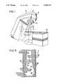
- FIG. 1is a perspective view of a radiation therapy system.
- FIG. 2is a side sectional view of the collimator of the present invention positioned within the radiation therapy system.
- FIG. 3is a top plan view of a multileaf collimator as seen from the source of the radiation therapy system.
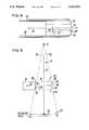
- FIG. 4is a side sectional view of a single leaf of the multileaf collimator.
- FIG. 5is a schematic view illustrating a leaf in its fully withdrawn position, thereby defining the tangent. The leaf is shown in its fully extended position in phantom.
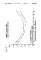
- FIG. 6illustrates calculated penumbra for a range of simple, curved leaf ends of constant radius.
- FIG. 7illustrates penumbra calculated for the present invention over its range of operation.
- FIGS. 8-11illustrate alternate embodiments of an asymmetric radius leaf end.
- FIGS. 1 to 5a multileaf collimator 2 is illustrated in accordance with the present invention.
- a gantry 4is shown in FIG. 1.
- Gantry 4includes a radiation head 6 for housing a radiation source 8.
- a patient support assembly 10is positioned within a radiation beam 9.
- Multileaf collimator 2is housed within a multileaf collimator system 12.
- a central axis 14 of radiation beam 9is coincident with the central axis of multileaf collimator 2.
- a pair of conventional movable collimators, identified as jaw-blocks or jaws 7is positioned to generally align the radiation beam with the treatment field to be irradiated, as seen in FIG. 2.
- the radiation treatment volumeis dependent on the shape of the tumor, as seen from radiation source 8.
- a plurality of leaves 16are independently movable with respect to jaws 7 in a longitudinal direction 22, oriented generally perpendicular to central axis 14.
- each leaf 16includes a leaf end 24 generally transverse to longitudinal direction 22.
- the particular shape of the leaf endsultimately determines the size of penumbra generated in conjunction with a radiation field.
- the shape of leaf end 24determines the extent to which leaves 16 can be extended across central axis 14, while still producing a radiation field with acceptable penumbra.
- Leaves 16are movable in longitudinal direction 22 from a fully retracted position as seen in solid lines in FIG. 5 to a fully extended position as seen in dashed lines in FIG. 5.
- the distance from central axis 14 to each of the fully withdrawn and fully extended positionsis 20 cm, at a reference plane 23 positioned 100 cm from the source of radiation.
- Isocenter 35is positioned on reference plane 23 at its intersection with central axis 14.
- proximal surface 39 of leaf 16The difference in geometry between a proximal surface 39 of leaf 16 and a distal surface 40 of the leaf causes proximal surface 39 to produce penumbra values that are greater than distal surface 40 because radiation source 8 appears larger, as seen from the proximal position.
- the geometric penumbrais dependent on the size of radiation source 8, the distance from the radiation source to either distal surface 40 or proximal surface 39, and the distance from radiation source 8 to reference plane 23.
- the equation for geometric penumbraby considering similar traingles, is:
- proximal surface 39is 48.2 cm from the radiation source 8 while distal surface 40 is 53.4 cm from the radiation source.
- the geometric penumbra factor for the distal surface 40will be: (source size) (0.873) while the geometric penumbra factor for proximal surface 39 will be (source size) (1.075). Therefore, in the preferred embodiment, the geometric penumbra for distal surface 40 will be (0.873/1.075) or 0.812 times as large as the geometric penumbra for proximal surface 39.
- the geometric penumbra factors calculated abovemust be compensated with transmission penumbra. Referring to FIG. 4, this is done by offsetting the axis of symmetry of the leaf end distally from the longitudinal axis 36 of leaf 16 by an offset distance 38.
- the amount of offset 38is chosen such that the amount of radiation attenuation in offset 38 is equal to the geometric penumbra factor between proximal and distal surfaces 39, 40.
- the offset thicknessis calculated as follows:
- uis the linear attenuation coefficient
- xis the desired offset distance to solve for
- Table 1lists calculated linear attenuation coefficients of several materials for common megavoltage x-ray beams.
- the calculated narrow-beam linear attenuation coefficients listed in Table 1can be used for megavoltage x-ray beams to calculate the required material thickness to achieve the desired offset.
- the linear attenuation coefficientcan be taken as 2.0 inches -1 . Substitution of the linear attenuation coefficient into the above equation yields an offset of 0.104 inches.
- the axis of symmetry of the leaf ends 24should have an offset 38 on the distal side of longitudinal axis 36 of leaves 16 of 0.104 inches.
- a first flat end 28 and a second flat end 30are directed at the edge of the radiation source when leaf 16 is fully extended or fully retracted, respectively, as seen in FIG. 5.
- a central portion 26 of leaf end 24is an arc of fixed radius, as measured from the point P. The radius of central portion 26 influences the overall penumbral performance of the leaf end. In the preferred embodiment, the radius of curvature R is 8 cm.
- jaw-blocks 7are positioned relative to patient support assembly 10 at the generally desired location such that the radiation field is positioned in the approximate desired area for treatment.
- Leaves 16are then driven on rails 20 to locate each respective leaf in the desired position for exactly defining the treatment volume of the tumor.
- First and second flat ends 28, 30 and central portion of leaf end 24allow leaves 16 to be positioned on either side of central axis 14, as seen in FIG. 5, while maintaining equal penumbra values for positions equidistant from central axis 14.
- the calculated multileaf penumbrais shown in FIG. 7.
- the figurerepresents leaf ends 16 retracted away from central axis 14 as positive position values, while leaf positions extended beyond central axis 14 are represented by negative position values.
- FIG. 7shows the calculated penumbra for a simple 8 cm constant radius, and an asymmetric 8 cm radius with flat surface tangents. (The asymmetric configuration can be seen in FIG. 4.) In both cases, the calculated penumbra values show the largest differences at the largest displacements from central axis, as is expected.
- Second flat end 30is shorter when leaf end 24 has an asymmetric configuration than if the leaf end 24 were symmetric about longitudinal axis 36 of leaf 16. As leaf 16 is retracted away from central axis 14, second flat end 30 defines the edge of the radiation field. It also rescatters charged secondary particles back into radiation beam 9. These charged secondary particles (typically electrons and positrons) increase the surface dose in the reference plane 23 and cause the depth of the maximum dose in the reference plane to vary as a function of the size of radiation beam 9. It is desirable to minimize both of these effects, and providing a shorter leaf second flat end 30 accomplishes this. The shorter surface makes it less probable for charged secondary particles to be rescattered into the radiation beam 9.
- charged secondary particlestypically electrons and positrons
- FIG. 8shows an alternate embodiment of the asymmetric leaf end where the asymmetric end is approximated by a polygon.
- the limit of a multifaceted polygonis a curved surface.
- the advantage of using a polygonis increased manufacturability, at the expense of increased transmission penumbra at the positions where the field edge is defined by a corner of the polygon.
- FIG. 9shows an alternate embodiment of the asymmetric radius leaf end where the leaf extends in the full lateral extent of the radiation field, what is normally called a jaw-block.
- FIG. 10shows an alternate embodiment of the asymmetric radius leaf end in which leaves 16 vary, dependent upon position.
- leaves 16are identical for ease of fabrication.
- FIG. 10shows leaves 16 with variable width in the direction parallel with rays from source 8. The embodiment of FIG. 10 would be required for multileaf collimators positioned close to an extended source, such that each leaf projected the same width onto the reference plane.
- FIG. 11shows an alternate embodiment of the asymmetric radius leaf end in which a linear radiation source is oriented perpendicularly to the motion of collimator leaves 16, rather than the generally circular sources typically used.
- the first and second flat ends and the asymmetric leaf end of the present inventionprovides uniform and minimized penumbra over the full range of travel of the collimator leaves, including travel across the central axis of the radiation source. Furthermore, the equal penumbra values for points equidistant from the central axis simplifies operation of multileaf collimator requiring no differentiation between retraction and extension of the individual leaves.
- variations and modificationscan be made to the preferred embodiment without departing from the scope of the present invention, which is limited only by the following claims.
Landscapes
- Health & Medical Sciences (AREA)
- Engineering & Computer Science (AREA)
- Biomedical Technology (AREA)
- General Health & Medical Sciences (AREA)
- Pathology (AREA)
- Nuclear Medicine, Radiotherapy & Molecular Imaging (AREA)
- Radiology & Medical Imaging (AREA)
- Life Sciences & Earth Sciences (AREA)
- Animal Behavior & Ethology (AREA)
- Public Health (AREA)
- Veterinary Medicine (AREA)
- Physics & Mathematics (AREA)
- High Energy & Nuclear Physics (AREA)
- General Engineering & Computer Science (AREA)
- Spectroscopy & Molecular Physics (AREA)
- Radiation-Therapy Devices (AREA)
Abstract
Description
penumbra=(source size)[(reference plane distance)-(leaf surface distance)]/(leaf surface distance)
e.sup.-ux =0.812,
TABLE 1 ______________________________________ Calculated Narrow-Beam, Linear Attenuation Coefficients. (inch.sup.-1)Atomic Density 10 25 Number (g/cm.sup.3) 4 MV 6 MV MV 15 MVMV ______________________________________ Al 4 2.70 0.365 0.316 0.256 0.215 0.186V 23 6.11 0.782 0.687 0.581 0.505 0.462Fe 26 7.87 1.06 0.924 0.812 0.708 0.667 Cu* 29 8.96 1.21 1.05 0.924 0.806 0.759 Sn 50 7.30 0.958 0.869 0.802 0.745 0.735 W 74 17.0 2.53 2.27 2.15 1.97 1.98 Pb* 82 11.3 1.60 1.51 1.43 1.31 1.32 ______________________________________ *Copper data scaled from iron data and lead data scaled from tungsten data, accounting for differences in density.
Claims (30)
Priority Applications (1)
| Application Number | Priority Date | Filing Date | Title |
|---|---|---|---|
| US07/740,164US5166531A (en) | 1991-08-05 | 1991-08-05 | Leaf-end configuration for multileaf collimator |
Applications Claiming Priority (1)
| Application Number | Priority Date | Filing Date | Title |
|---|---|---|---|
| US07/740,164US5166531A (en) | 1991-08-05 | 1991-08-05 | Leaf-end configuration for multileaf collimator |
Publications (1)
| Publication Number | Publication Date |
|---|---|
| US5166531Atrue US5166531A (en) | 1992-11-24 |
Family
ID=24975324
Family Applications (1)
| Application Number | Title | Priority Date | Filing Date |
|---|---|---|---|
| US07/740,164Expired - LifetimeUS5166531A (en) | 1991-08-05 | 1991-08-05 | Leaf-end configuration for multileaf collimator |
Country Status (1)
| Country | Link |
|---|---|
| US (1) | US5166531A (en) |
Cited By (66)
| Publication number | Priority date | Publication date | Assignee | Title |
|---|---|---|---|---|
| US5343048A (en)* | 1992-02-07 | 1994-08-30 | Siemens Aktiengesellschaft | Contour collimator for radiation therapy |
| US5591983A (en)* | 1995-06-30 | 1997-01-07 | Siemens Medical Systems, Inc. | Multiple layer multileaf collimator |
| US5668371A (en)* | 1995-06-06 | 1997-09-16 | Wisconsin Alumni Research Foundation | Method and apparatus for proton therapy |
| US5757881A (en)* | 1997-01-06 | 1998-05-26 | Siemens Business Communication Systems, Inc. | Redundant field-defining arrays for a radiation system |
| US5889834A (en)* | 1995-09-28 | 1999-03-30 | Brainlab Med. Computersysteme Gmbh | Blade collimator for radiation therapy |
| US5892238A (en)* | 1997-05-02 | 1999-04-06 | Bionix Development Corp. | Radiation therapy shielding assembly |
| US5907157A (en)* | 1996-02-01 | 1999-05-25 | Jeol Ltd. | Method and apparatus for preparing specimen |
| US6041101A (en)* | 1996-10-25 | 2000-03-21 | Radionics, Inc. | Jaw and circular collimator |
| US6052430A (en)* | 1997-09-25 | 2000-04-18 | Siemens Medical Systems, Inc. | Dynamic sub-space intensity modulation |
| US6052436A (en)* | 1997-07-16 | 2000-04-18 | Bionix Development Corporation | Radiation therapy device employing cam pin and cam groove guiding system for controlling movement of linear multi-leaf collimator leaves |
| US6060718A (en)* | 1998-02-26 | 2000-05-09 | Eaton Corporation | Ion source having wide output current operating range |
| DE19905823C1 (en)* | 1999-02-12 | 2000-06-08 | Deutsches Krebsforsch | Collimator for high energy radiation, e.g. for the treatment of tumors, comprises numerous opposing scree sections made of radiation absorbing material |
| FR2788439A1 (en) | 1999-01-20 | 2000-07-21 | Siemens Medical Systems Inc | INTEGRATED MULTI-SHEET HIGH DEFINITION INTENSITY COLLIMATOR SYSTEM WHICH ENHANCES IMPROVED CONFORMING RADIATION THERAPY, WHILE MINIMIZING LEAKAGE |
| US6266393B1 (en) | 1997-09-29 | 2001-07-24 | Moshe Ein-Gal | Multiple layer multileaf collimator |
| US6320938B1 (en) | 1998-10-28 | 2001-11-20 | F & L Medical Products | Method of X-ray protection during diagnostic CT imaging |
| US6322249B1 (en)* | 1999-07-26 | 2001-11-27 | Siemens Medical Solutions Usa, Inc. | System and method for automatic calibration of a multileaf collimator |
| GB2367993A (en)* | 2000-10-11 | 2002-04-17 | Elekta Ab | Radiotherapy apparatus |
| US6388816B2 (en)* | 2000-04-28 | 2002-05-14 | Elekta Ab | Multi-leaf collimator |
| US6459769B1 (en) | 1999-05-03 | 2002-10-01 | Sherwood Services Ag | Movable miniature multi-leaf collimator |
| US6600810B1 (en) | 1998-08-10 | 2003-07-29 | Siemens Medical Solutions Usa, Inc. | Multiple layer multileaf collimator design to improve resolution and reduce leakage |
| US20050008123A1 (en)* | 2003-07-08 | 2005-01-13 | Department Of Radiotherapy University Hospital Utecht | Multi-leaf collimator |
| US6853705B2 (en) | 2003-03-28 | 2005-02-08 | The University Of North Carolina At Chapel Hill | Residual map segmentation method for multi-leaf collimator-intensity modulated radiotherapy |
| US20050059879A1 (en)* | 2003-09-16 | 2005-03-17 | Robert Sutherland | Localization of a sensor device in a body |
| WO2005036124A2 (en) | 2003-09-16 | 2005-04-21 | Varian Medical Systems Technologies, Inc. | Localization of a target using in vivo markers |
| US20070086576A1 (en)* | 2003-11-20 | 2007-04-19 | Zhao Yang | Collimator and radiation irradiator |
| US20070171015A1 (en)* | 2006-01-19 | 2007-07-26 | Massachusetts Institute Of Technology | High-Field Superconducting Synchrocyclotron |
| US20080063147A1 (en)* | 2006-09-12 | 2008-03-13 | John Juschka | Multileaf collimator |
| US20080073591A1 (en)* | 2006-04-21 | 2008-03-27 | Stephen Mohr | System and method for high resolution radiation field shaping |
| CN100464377C (en)* | 2001-10-23 | 2009-02-25 | 深圳市一体智能技术有限公司 | Blade regulating method of multi-blade collimator and multi-blade collimator |
| US20090084984A1 (en)* | 2007-09-28 | 2009-04-02 | Siemens Medical Solutions Usa, Inc. | Irradiation system and method |
| US7656258B1 (en) | 2006-01-19 | 2010-02-02 | Massachusetts Institute Of Technology | Magnet structure for particle acceleration |
| US7728311B2 (en) | 2005-11-18 | 2010-06-01 | Still River Systems Incorporated | Charged particle radiation therapy |
| US8003964B2 (en) | 2007-10-11 | 2011-08-23 | Still River Systems Incorporated | Applying a particle beam to a patient |
| EP2095373A4 (en)* | 2006-12-19 | 2012-07-18 | C Rad Innovation Ab | Collimator |
| US8581523B2 (en) | 2007-11-30 | 2013-11-12 | Mevion Medical Systems, Inc. | Interrupted particle source |
| US8791656B1 (en) | 2013-05-31 | 2014-07-29 | Mevion Medical Systems, Inc. | Active return system |
| WO2014111869A3 (en)* | 2013-01-17 | 2014-11-13 | Panacea Medical Technologies Pvt. Ltd | An apparatus to deliver conformal radiotherapy using external beam cobalt 60 |
| US8927950B2 (en) | 2012-09-28 | 2015-01-06 | Mevion Medical Systems, Inc. | Focusing a particle beam |
| US8933650B2 (en) | 2007-11-30 | 2015-01-13 | Mevion Medical Systems, Inc. | Matching a resonant frequency of a resonant cavity to a frequency of an input voltage |
| US8952634B2 (en) | 2004-07-21 | 2015-02-10 | Mevion Medical Systems, Inc. | Programmable radio frequency waveform generator for a synchrocyclotron |
| WO2015063232A3 (en)* | 2013-10-31 | 2015-06-25 | Fraunhofer-Gesellschaft zur Förderung der angewandten Forschung e.V. | Diaphragm system for a radiation source, and device and method for recording a projection image and for determining a relative position between a radiation source and a radiation detector |
| CN104795122A (en)* | 2014-05-28 | 2015-07-22 | 上海联影医疗科技有限公司 | Selection method of collimator, radiation system and collimator blades |
| US9155186B2 (en) | 2012-09-28 | 2015-10-06 | Mevion Medical Systems, Inc. | Focusing a particle beam using magnetic field flutter |
| US9185789B2 (en) | 2012-09-28 | 2015-11-10 | Mevion Medical Systems, Inc. | Magnetic shims to alter magnetic fields |
| US9301384B2 (en) | 2012-09-28 | 2016-03-29 | Mevion Medical Systems, Inc. | Adjusting energy of a particle beam |
| US9545528B2 (en) | 2012-09-28 | 2017-01-17 | Mevion Medical Systems, Inc. | Controlling particle therapy |
| CN106500577A (en)* | 2016-10-20 | 2017-03-15 | 山东省千佛山医院 | A kind of clinac vane grating method for detecting position |
| US9622335B2 (en) | 2012-09-28 | 2017-04-11 | Mevion Medical Systems, Inc. | Magnetic field regenerator |
| US9661736B2 (en) | 2014-02-20 | 2017-05-23 | Mevion Medical Systems, Inc. | Scanning system for a particle therapy system |
| US9681531B2 (en) | 2012-09-28 | 2017-06-13 | Mevion Medical Systems, Inc. | Control system for a particle accelerator |
| US9723705B2 (en) | 2012-09-28 | 2017-08-01 | Mevion Medical Systems, Inc. | Controlling intensity of a particle beam |
| US9730308B2 (en) | 2013-06-12 | 2017-08-08 | Mevion Medical Systems, Inc. | Particle accelerator that produces charged particles having variable energies |
| US9950194B2 (en) | 2014-09-09 | 2018-04-24 | Mevion Medical Systems, Inc. | Patient positioning system |
| US9962560B2 (en) | 2013-12-20 | 2018-05-08 | Mevion Medical Systems, Inc. | Collimator and energy degrader |
| CN108778138A (en)* | 2016-02-05 | 2018-11-09 | 韩国威泰有限公司 | X-ray collimator and use its x-ray imaging equipment |
| US10254739B2 (en) | 2012-09-28 | 2019-04-09 | Mevion Medical Systems, Inc. | Coil positioning system |
| US10258810B2 (en) | 2013-09-27 | 2019-04-16 | Mevion Medical Systems, Inc. | Particle beam scanning |
| GB2569154A (en)* | 2017-12-07 | 2019-06-12 | Elekta ltd | Methods and systems for determining the shape of a radiotherapy beam |
| US10646728B2 (en) | 2015-11-10 | 2020-05-12 | Mevion Medical Systems, Inc. | Adaptive aperture |
| US10653892B2 (en) | 2017-06-30 | 2020-05-19 | Mevion Medical Systems, Inc. | Configurable collimator controlled using linear motors |
| US10675487B2 (en) | 2013-12-20 | 2020-06-09 | Mevion Medical Systems, Inc. | Energy degrader enabling high-speed energy switching |
| US10773102B2 (en)* | 2010-02-12 | 2020-09-15 | Elekta Ab (Publ) | Radiotherapy and imaging apparatus |
| US10925147B2 (en) | 2016-07-08 | 2021-02-16 | Mevion Medical Systems, Inc. | Treatment planning |
| US11000706B2 (en) | 2016-12-13 | 2021-05-11 | Viewray Technologies, Inc. | Radiation therapy systems and methods |
| US11103730B2 (en) | 2017-02-23 | 2021-08-31 | Mevion Medical Systems, Inc. | Automated treatment in particle therapy |
| US11291861B2 (en) | 2019-03-08 | 2022-04-05 | Mevion Medical Systems, Inc. | Delivery of radiation by column and generating a treatment plan therefor |
Citations (6)
| Publication number | Priority date | Publication date | Assignee | Title |
|---|---|---|---|---|
| US3227880A (en)* | 1963-08-29 | 1966-01-04 | Bbc Brown Boveri & Cie | Collimator for beams of high-velocity electrons |
| US4157475A (en)* | 1977-10-21 | 1979-06-05 | Applied Radiation Corporation | Electron accelerator comprising a target exposed to the electron beam |
| US4534052A (en)* | 1982-04-02 | 1985-08-06 | C.G.R. - Mev | Block for partially limiting a radiation beam, and a collimator comprising such blocks |
| US4672212A (en)* | 1985-02-28 | 1987-06-09 | Instrument Ab Scanditronax | Multi leaf collimator |
| US4868843A (en)* | 1986-09-10 | 1989-09-19 | Varian Associates, Inc. | Multileaf collimator and compensator for radiotherapy machines |
| US5012506A (en)* | 1987-10-28 | 1991-04-30 | U.S. Philips Corporation | Multileaf collimator |
- 1991
- 1991-08-05USUS07/740,164patent/US5166531A/ennot_activeExpired - Lifetime
Patent Citations (6)
| Publication number | Priority date | Publication date | Assignee | Title |
|---|---|---|---|---|
| US3227880A (en)* | 1963-08-29 | 1966-01-04 | Bbc Brown Boveri & Cie | Collimator for beams of high-velocity electrons |
| US4157475A (en)* | 1977-10-21 | 1979-06-05 | Applied Radiation Corporation | Electron accelerator comprising a target exposed to the electron beam |
| US4534052A (en)* | 1982-04-02 | 1985-08-06 | C.G.R. - Mev | Block for partially limiting a radiation beam, and a collimator comprising such blocks |
| US4672212A (en)* | 1985-02-28 | 1987-06-09 | Instrument Ab Scanditronax | Multi leaf collimator |
| US4868843A (en)* | 1986-09-10 | 1989-09-19 | Varian Associates, Inc. | Multileaf collimator and compensator for radiotherapy machines |
| US5012506A (en)* | 1987-10-28 | 1991-04-30 | U.S. Philips Corporation | Multileaf collimator |
Non-Patent Citations (4)
| Title |
|---|
| Maleki, N. et al., "Analysis of the Field Defining Properties of a Multi-Leaf Collimator", Medical Physics, vol. 10, No. 4, (abstract), Jul./Aug. 1983. |
| Maleki, N. et al., Analysis of the Field Defining Properties of a Multi Leaf Collimator , Medical Physics, vol. 10, No. 4, (abstract), Jul./Aug. 1983.* |
| Sutherland, W. H. et al., "Design Principles of Telecobalt Collimators", Physics in Medicine and Biology, 22, 1189-1196 (1977). |
| Sutherland, W. H. et al., Design Principles of Telecobalt Collimators , Physics in Medicine and Biology, 22, 1189 1196 (1977).* |
Cited By (114)
| Publication number | Priority date | Publication date | Assignee | Title |
|---|---|---|---|---|
| US5343048A (en)* | 1992-02-07 | 1994-08-30 | Siemens Aktiengesellschaft | Contour collimator for radiation therapy |
| US5668371A (en)* | 1995-06-06 | 1997-09-16 | Wisconsin Alumni Research Foundation | Method and apparatus for proton therapy |
| US5591983A (en)* | 1995-06-30 | 1997-01-07 | Siemens Medical Systems, Inc. | Multiple layer multileaf collimator |
| US5889834A (en)* | 1995-09-28 | 1999-03-30 | Brainlab Med. Computersysteme Gmbh | Blade collimator for radiation therapy |
| US5907157A (en)* | 1996-02-01 | 1999-05-25 | Jeol Ltd. | Method and apparatus for preparing specimen |
| US6278766B1 (en)* | 1996-10-25 | 2001-08-21 | Sherwood Services Ag | Jaw and circular collimator |
| US6041101A (en)* | 1996-10-25 | 2000-03-21 | Radionics, Inc. | Jaw and circular collimator |
| US5757881A (en)* | 1997-01-06 | 1998-05-26 | Siemens Business Communication Systems, Inc. | Redundant field-defining arrays for a radiation system |
| US5892238A (en)* | 1997-05-02 | 1999-04-06 | Bionix Development Corp. | Radiation therapy shielding assembly |
| US6052436A (en)* | 1997-07-16 | 2000-04-18 | Bionix Development Corporation | Radiation therapy device employing cam pin and cam groove guiding system for controlling movement of linear multi-leaf collimator leaves |
| US6052430A (en)* | 1997-09-25 | 2000-04-18 | Siemens Medical Systems, Inc. | Dynamic sub-space intensity modulation |
| US6266393B1 (en) | 1997-09-29 | 2001-07-24 | Moshe Ein-Gal | Multiple layer multileaf collimator |
| US6060718A (en)* | 1998-02-26 | 2000-05-09 | Eaton Corporation | Ion source having wide output current operating range |
| US6600810B1 (en) | 1998-08-10 | 2003-07-29 | Siemens Medical Solutions Usa, Inc. | Multiple layer multileaf collimator design to improve resolution and reduce leakage |
| US6320938B1 (en) | 1998-10-28 | 2001-11-20 | F & L Medical Products | Method of X-ray protection during diagnostic CT imaging |
| FR2788439A1 (en) | 1999-01-20 | 2000-07-21 | Siemens Medical Systems Inc | INTEGRATED MULTI-SHEET HIGH DEFINITION INTENSITY COLLIMATOR SYSTEM WHICH ENHANCES IMPROVED CONFORMING RADIATION THERAPY, WHILE MINIMIZING LEAKAGE |
| US6730924B1 (en) | 1999-02-12 | 2004-05-04 | Deutsches Krebsforschungszentrum Stiftung Des Oeffentlichen Rechts | Collimator for limiting a bundle of high-energy rays |
| DE19905823C1 (en)* | 1999-02-12 | 2000-06-08 | Deutsches Krebsforsch | Collimator for high energy radiation, e.g. for the treatment of tumors, comprises numerous opposing scree sections made of radiation absorbing material |
| US6459769B1 (en) | 1999-05-03 | 2002-10-01 | Sherwood Services Ag | Movable miniature multi-leaf collimator |
| US6322249B1 (en)* | 1999-07-26 | 2001-11-27 | Siemens Medical Solutions Usa, Inc. | System and method for automatic calibration of a multileaf collimator |
| US6388816B2 (en)* | 2000-04-28 | 2002-05-14 | Elekta Ab | Multi-leaf collimator |
| WO2002031837A1 (en)* | 2000-10-11 | 2002-04-18 | Elekta Ab (Publ) | Radiotherapy apparatus and collimator set therefor |
| US20040013237A1 (en)* | 2000-10-11 | 2004-01-22 | Brown Kevin John | Radiotherapy apparatus and collimator set therefor |
| GB2367993A (en)* | 2000-10-11 | 2002-04-17 | Elekta Ab | Radiotherapy apparatus |
| GB2367993B (en)* | 2000-10-11 | 2005-04-20 | Elekta Ab | Radiotherapy apparatus |
| CN100464377C (en)* | 2001-10-23 | 2009-02-25 | 深圳市一体智能技术有限公司 | Blade regulating method of multi-blade collimator and multi-blade collimator |
| US6853705B2 (en) | 2003-03-28 | 2005-02-08 | The University Of North Carolina At Chapel Hill | Residual map segmentation method for multi-leaf collimator-intensity modulated radiotherapy |
| US20050008123A1 (en)* | 2003-07-08 | 2005-01-13 | Department Of Radiotherapy University Hospital Utecht | Multi-leaf collimator |
| WO2005004987A1 (en)* | 2003-07-08 | 2005-01-20 | Elekta Ab (Publ) | Multi-leaf collimator |
| CN100569316C (en)* | 2003-07-08 | 2009-12-16 | 埃莱克特公司 | Multi-blade collimator |
| US7095823B2 (en)* | 2003-07-08 | 2006-08-22 | Elekta Ab (Publ) | Multi-leaf collimator |
| WO2005036124A2 (en) | 2003-09-16 | 2005-04-21 | Varian Medical Systems Technologies, Inc. | Localization of a target using in vivo markers |
| US20050059879A1 (en)* | 2003-09-16 | 2005-03-17 | Robert Sutherland | Localization of a sensor device in a body |
| US7397903B2 (en)* | 2003-11-20 | 2008-07-08 | Ge Medical Systems Global Technology Company, Llc | Collimator and radiation irradiator |
| US20070086576A1 (en)* | 2003-11-20 | 2007-04-19 | Zhao Yang | Collimator and radiation irradiator |
| USRE48047E1 (en) | 2004-07-21 | 2020-06-09 | Mevion Medical Systems, Inc. | Programmable radio frequency waveform generator for a synchrocyclotron |
| US8952634B2 (en) | 2004-07-21 | 2015-02-10 | Mevion Medical Systems, Inc. | Programmable radio frequency waveform generator for a synchrocyclotron |
| US9925395B2 (en) | 2005-11-18 | 2018-03-27 | Mevion Medical Systems, Inc. | Inner gantry |
| US8916843B2 (en) | 2005-11-18 | 2014-12-23 | Mevion Medical Systems, Inc. | Inner gantry |
| US8907311B2 (en) | 2005-11-18 | 2014-12-09 | Mevion Medical Systems, Inc. | Charged particle radiation therapy |
| US10279199B2 (en) | 2005-11-18 | 2019-05-07 | Mevion Medical Systems, Inc. | Inner gantry |
| US7728311B2 (en) | 2005-11-18 | 2010-06-01 | Still River Systems Incorporated | Charged particle radiation therapy |
| US9452301B2 (en) | 2005-11-18 | 2016-09-27 | Mevion Medical Systems, Inc. | Inner gantry |
| US10722735B2 (en) | 2005-11-18 | 2020-07-28 | Mevion Medical Systems, Inc. | Inner gantry |
| US8344340B2 (en) | 2005-11-18 | 2013-01-01 | Mevion Medical Systems, Inc. | Inner gantry |
| US7541905B2 (en) | 2006-01-19 | 2009-06-02 | Massachusetts Institute Of Technology | High-field superconducting synchrocyclotron |
| US7696847B2 (en) | 2006-01-19 | 2010-04-13 | Massachusetts Institute Of Technology | High-field synchrocyclotron |
| US7656258B1 (en) | 2006-01-19 | 2010-02-02 | Massachusetts Institute Of Technology | Magnet structure for particle acceleration |
| US20090206967A1 (en)* | 2006-01-19 | 2009-08-20 | Massachusetts Institute Of Technology | High-Field Synchrocyclotron |
| US20070171015A1 (en)* | 2006-01-19 | 2007-07-26 | Massachusetts Institute Of Technology | High-Field Superconducting Synchrocyclotron |
| US7507975B2 (en) | 2006-04-21 | 2009-03-24 | Varian Medical Systems, Inc. | System and method for high resolution radiation field shaping |
| US8067751B2 (en) | 2006-04-21 | 2011-11-29 | Varian Medical Systems, Inc. | System and method for high resolution field shaping |
| EP2020006A4 (en)* | 2006-04-21 | 2011-06-29 | Varian Med Sys Inc | SYSTEM AND METHOD FOR SHAPING A FIELD OF HIGH-RESOLUTION RADIATION |
| US20080073591A1 (en)* | 2006-04-21 | 2008-03-27 | Stephen Mohr | System and method for high resolution radiation field shaping |
| US20080063147A1 (en)* | 2006-09-12 | 2008-03-13 | John Juschka | Multileaf collimator |
| US7558378B2 (en) | 2006-09-12 | 2009-07-07 | Siemens Aktiengesellschaft | Multileaf collimator |
| EP2095373A4 (en)* | 2006-12-19 | 2012-07-18 | C Rad Innovation Ab | Collimator |
| US20090084984A1 (en)* | 2007-09-28 | 2009-04-02 | Siemens Medical Solutions Usa, Inc. | Irradiation system and method |
| US8941083B2 (en) | 2007-10-11 | 2015-01-27 | Mevion Medical Systems, Inc. | Applying a particle beam to a patient |
| US8003964B2 (en) | 2007-10-11 | 2011-08-23 | Still River Systems Incorporated | Applying a particle beam to a patient |
| US8933650B2 (en) | 2007-11-30 | 2015-01-13 | Mevion Medical Systems, Inc. | Matching a resonant frequency of a resonant cavity to a frequency of an input voltage |
| US8970137B2 (en) | 2007-11-30 | 2015-03-03 | Mevion Medical Systems, Inc. | Interrupted particle source |
| USRE48317E1 (en) | 2007-11-30 | 2020-11-17 | Mevion Medical Systems, Inc. | Interrupted particle source |
| US8581523B2 (en) | 2007-11-30 | 2013-11-12 | Mevion Medical Systems, Inc. | Interrupted particle source |
| US10773102B2 (en)* | 2010-02-12 | 2020-09-15 | Elekta Ab (Publ) | Radiotherapy and imaging apparatus |
| US9622335B2 (en) | 2012-09-28 | 2017-04-11 | Mevion Medical Systems, Inc. | Magnetic field regenerator |
| US9706636B2 (en) | 2012-09-28 | 2017-07-11 | Mevion Medical Systems, Inc. | Adjusting energy of a particle beam |
| US9545528B2 (en) | 2012-09-28 | 2017-01-17 | Mevion Medical Systems, Inc. | Controlling particle therapy |
| US9185789B2 (en) | 2012-09-28 | 2015-11-10 | Mevion Medical Systems, Inc. | Magnetic shims to alter magnetic fields |
| US10155124B2 (en) | 2012-09-28 | 2018-12-18 | Mevion Medical Systems, Inc. | Controlling particle therapy |
| US9155186B2 (en) | 2012-09-28 | 2015-10-06 | Mevion Medical Systems, Inc. | Focusing a particle beam using magnetic field flutter |
| US9681531B2 (en) | 2012-09-28 | 2017-06-13 | Mevion Medical Systems, Inc. | Control system for a particle accelerator |
| US9301384B2 (en) | 2012-09-28 | 2016-03-29 | Mevion Medical Systems, Inc. | Adjusting energy of a particle beam |
| US9723705B2 (en) | 2012-09-28 | 2017-08-01 | Mevion Medical Systems, Inc. | Controlling intensity of a particle beam |
| US10254739B2 (en) | 2012-09-28 | 2019-04-09 | Mevion Medical Systems, Inc. | Coil positioning system |
| US8927950B2 (en) | 2012-09-28 | 2015-01-06 | Mevion Medical Systems, Inc. | Focusing a particle beam |
| US10368429B2 (en) | 2012-09-28 | 2019-07-30 | Mevion Medical Systems, Inc. | Magnetic field regenerator |
| WO2014111869A3 (en)* | 2013-01-17 | 2014-11-13 | Panacea Medical Technologies Pvt. Ltd | An apparatus to deliver conformal radiotherapy using external beam cobalt 60 |
| US8791656B1 (en) | 2013-05-31 | 2014-07-29 | Mevion Medical Systems, Inc. | Active return system |
| US9730308B2 (en) | 2013-06-12 | 2017-08-08 | Mevion Medical Systems, Inc. | Particle accelerator that produces charged particles having variable energies |
| US10456591B2 (en) | 2013-09-27 | 2019-10-29 | Mevion Medical Systems, Inc. | Particle beam scanning |
| US10258810B2 (en) | 2013-09-27 | 2019-04-16 | Mevion Medical Systems, Inc. | Particle beam scanning |
| WO2015063232A3 (en)* | 2013-10-31 | 2015-06-25 | Fraunhofer-Gesellschaft zur Förderung der angewandten Forschung e.V. | Diaphragm system for a radiation source, and device and method for recording a projection image and for determining a relative position between a radiation source and a radiation detector |
| US9962560B2 (en) | 2013-12-20 | 2018-05-08 | Mevion Medical Systems, Inc. | Collimator and energy degrader |
| US10675487B2 (en) | 2013-12-20 | 2020-06-09 | Mevion Medical Systems, Inc. | Energy degrader enabling high-speed energy switching |
| US11717700B2 (en) | 2014-02-20 | 2023-08-08 | Mevion Medical Systems, Inc. | Scanning system |
| US10434331B2 (en) | 2014-02-20 | 2019-10-08 | Mevion Medical Systems, Inc. | Scanning system |
| US9661736B2 (en) | 2014-02-20 | 2017-05-23 | Mevion Medical Systems, Inc. | Scanning system for a particle therapy system |
| CN107362463A (en)* | 2014-05-28 | 2017-11-21 | 上海联影医疗科技有限公司 | The choosing method of collimater, radiating system and collimators vanes |
| CN104795122B (en)* | 2014-05-28 | 2017-11-28 | 上海联影医疗科技有限公司 | Selection method of collimator, radiation system and collimator blades |
| CN107362463B (en)* | 2014-05-28 | 2020-03-31 | 上海联影医疗科技有限公司 | Collimator, radiation system and selection method of collimator blades |
| CN104795122A (en)* | 2014-05-28 | 2015-07-22 | 上海联影医疗科技有限公司 | Selection method of collimator, radiation system and collimator blades |
| US9950194B2 (en) | 2014-09-09 | 2018-04-24 | Mevion Medical Systems, Inc. | Patient positioning system |
| US10786689B2 (en) | 2015-11-10 | 2020-09-29 | Mevion Medical Systems, Inc. | Adaptive aperture |
| US11786754B2 (en) | 2015-11-10 | 2023-10-17 | Mevion Medical Systems, Inc. | Adaptive aperture |
| US10646728B2 (en) | 2015-11-10 | 2020-05-12 | Mevion Medical Systems, Inc. | Adaptive aperture |
| US11213697B2 (en) | 2015-11-10 | 2022-01-04 | Mevion Medical Systems, Inc. | Adaptive aperture |
| CN108778138A (en)* | 2016-02-05 | 2018-11-09 | 韩国威泰有限公司 | X-ray collimator and use its x-ray imaging equipment |
| CN108778138B (en)* | 2016-02-05 | 2021-12-21 | 韩国威泰有限公司 | X-ray collimator and X-ray imaging apparatus using the same |
| US12150235B2 (en) | 2016-07-08 | 2024-11-19 | Mevion Medical Systems, Inc. | Treatment planning |
| US10925147B2 (en) | 2016-07-08 | 2021-02-16 | Mevion Medical Systems, Inc. | Treatment planning |
| CN106500577A (en)* | 2016-10-20 | 2017-03-15 | 山东省千佛山医院 | A kind of clinac vane grating method for detecting position |
| US11931602B2 (en) | 2016-12-13 | 2024-03-19 | Viewray Technologies, Inc. | Radiation therapy systems and methods |
| US11000706B2 (en) | 2016-12-13 | 2021-05-11 | Viewray Technologies, Inc. | Radiation therapy systems and methods |
| US11103730B2 (en) | 2017-02-23 | 2021-08-31 | Mevion Medical Systems, Inc. | Automated treatment in particle therapy |
| US10653892B2 (en) | 2017-06-30 | 2020-05-19 | Mevion Medical Systems, Inc. | Configurable collimator controlled using linear motors |
| GB2569154A (en)* | 2017-12-07 | 2019-06-12 | Elekta ltd | Methods and systems for determining the shape of a radiotherapy beam |
| GB2569154B (en)* | 2017-12-07 | 2020-04-22 | Elekta ltd | Methods and systems for determining the shape of a radiotherapy beam |
| US10818404B2 (en) | 2017-12-07 | 2020-10-27 | Elekta Limited | Methods and systems for determining the shape of a radiotherapy beam |
| US11311746B2 (en) | 2019-03-08 | 2022-04-26 | Mevion Medical Systems, Inc. | Collimator and energy degrader for a particle therapy system |
| US11717703B2 (en) | 2019-03-08 | 2023-08-08 | Mevion Medical Systems, Inc. | Delivery of radiation by column and generating a treatment plan therefor |
| US11291861B2 (en) | 2019-03-08 | 2022-04-05 | Mevion Medical Systems, Inc. | Delivery of radiation by column and generating a treatment plan therefor |
| US12161885B2 (en) | 2019-03-08 | 2024-12-10 | Mevion Medical Systems, Inc. | Delivery of radiation by column and generating a treatment plan therefor |
| US12168147B2 (en) | 2019-03-08 | 2024-12-17 | Mevion Medical Systems, Inc. | Collimator and energy degrader for a particle therapy system |
Similar Documents
| Publication | Publication Date | Title |
|---|---|---|
| US5166531A (en) | Leaf-end configuration for multileaf collimator | |
| EP0751532B1 (en) | A multiple layer multileaf collimator | |
| EP1641534B1 (en) | Multi-leaf collimator | |
| US6526123B2 (en) | Multiple layer multileaf collimator | |
| US6266393B1 (en) | Multiple layer multileaf collimator | |
| US7054413B2 (en) | Rotatable multi-element beam shaping device | |
| Galvin et al. | Evaluation of multileaf collimator design for a photon beam | |
| US5757881A (en) | Redundant field-defining arrays for a radiation system | |
| US10583311B2 (en) | Collimation apparatus for radiotherapy | |
| Brahme | Optimization of radiation therapy and the development of multileaf collimation | |
| JP2010527664A (en) | Aiming device for radiation therapy | |
| EP3902602B1 (en) | Multileaf collimator with alternating trapezoidal leaf geometry design | |
| WO2019196137A1 (en) | Radio-therapeutic head and radio-therapeutic device | |
| US10315051B2 (en) | Collimator for radiotherapy apparatus | |
| Fernandez et al. | The acceptability of a multileaf collimator as a replacement for conventional blocks | |
| CN219307780U (en) | Multi-leaf collimator | |
| US20130034211A1 (en) | Radiotherapy | |
| WO2021170722A1 (en) | Beam-blocking leaf and multileaf collimator containing same | |
| US20220280812A1 (en) | Srs contoured multi-layer multileaf collimator | |
| Galvin et al. | Dosimetric characterization of a multileaf collimator system | |
| Kligerman et al. | Initiation of multileaf collimator-based conformal radiation therapy |
Legal Events
| Date | Code | Title | Description |
|---|---|---|---|
| AS | Assignment | Owner name:VARIAN ASSOCIATES, INC. A CORPORATION OF DE, CA Free format text:ASSIGNMENT OF ASSIGNORS INTEREST.;ASSIGNOR:HUNTZINGER, CALVIN J.;REEL/FRAME:005919/0896 Effective date:19910805 | |
| STCF | Information on status: patent grant | Free format text:PATENTED CASE | |
| FEPP | Fee payment procedure | Free format text:PAYOR NUMBER ASSIGNED (ORIGINAL EVENT CODE: ASPN); ENTITY STATUS OF PATENT OWNER: LARGE ENTITY | |
| FPAY | Fee payment | Year of fee payment:4 | |
| FPAY | Fee payment | Year of fee payment:8 | |
| AS | Assignment | Owner name:VARIAN MEDICAL SYSTEMS TECHNOLOGIES, INC., CALIFOR Free format text:ASSIGNMENT OF ASSIGNORS INTEREST;ASSIGNOR:VARIAN MEDICAL SYSTEMS, INC.;REEL/FRAME:014027/0459 Effective date:20030925 | |
| AS | Assignment | Owner name:VARIAN MEDICAL SYTEMS, INC., CALIFORNIA Free format text:CHANGE OF NAME;ASSIGNOR:VARIAN ASSOCIATES, INC;REEL/FRAME:014007/0490 Effective date:19990321 | |
| FPAY | Fee payment | Year of fee payment:12 | |
| AS | Assignment | Owner name:VARIAN MEDICAL SYSTEMS, INC., CALIFORNIA Free format text:MERGER;ASSIGNOR:VARIAN MEDICAL SYSTEMS TECHNOLOGIES, INC.;REEL/FRAME:021669/0848 Effective date:20080926 |