US5165540A - Angiographic catheter package - Google Patents
Angiographic catheter packageDownload PDFInfo
- Publication number
- US5165540A US5165540AUS07/463,092US46309290AUS5165540AUS 5165540 AUS5165540 AUS 5165540AUS 46309290 AUS46309290 AUS 46309290AUS 5165540 AUS5165540 AUS 5165540A
- Authority
- US
- United States
- Prior art keywords
- catheter
- channel
- section
- tip
- base section
- Prior art date
- Legal status (The legal status is an assumption and is not a legal conclusion. Google has not performed a legal analysis and makes no representation as to the accuracy of the status listed.)
- Expired - Lifetime
Links
- 230000001954sterilising effectEffects0.000claimsabstractdescription39
- 238000004659sterilization and disinfectionMethods0.000claimsabstractdescription38
- 238000003860storageMethods0.000claimsabstractdescription30
- 230000000717retained effectEffects0.000claimsdescription12
- 238000004806packaging method and processMethods0.000claimsdescription3
- 230000008602contractionEffects0.000claimsdescription2
- 230000004044responseEffects0.000claimsdescription2
- 239000004033plasticSubstances0.000description12
- 238000013459approachMethods0.000description7
- 238000005728strengtheningMethods0.000description6
- 230000008901benefitEffects0.000description5
- 230000008859changeEffects0.000description4
- 210000001349mammary arteryAnatomy0.000description4
- 210000004351coronary vesselAnatomy0.000description3
- 238000004519manufacturing processMethods0.000description3
- 238000000034methodMethods0.000description3
- 230000008569processEffects0.000description3
- 230000002792vascularEffects0.000description3
- 210000004204blood vesselAnatomy0.000description2
- 210000005240left ventricleAnatomy0.000description2
- 239000000463materialSubstances0.000description2
- 230000002861ventricularEffects0.000description2
- 238000012800visualizationMethods0.000description2
- 241000894006BacteriaSpecies0.000description1
- IAYPIBMASNFSPL-UHFFFAOYSA-NEthylene oxideChemical compoundC1CO1IAYPIBMASNFSPL-UHFFFAOYSA-N0.000description1
- 239000004743PolypropyleneSubstances0.000description1
- 230000009471actionEffects0.000description1
- 238000002583angiographyMethods0.000description1
- 230000003466anti-cipated effectEffects0.000description1
- 230000007423decreaseEffects0.000description1
- 230000002950deficientEffects0.000description1
- 239000012502diagnostic productSubstances0.000description1
- 230000006872improvementEffects0.000description1
- 229920006289polycarbonate filmPolymers0.000description1
- -1polypropylenePolymers0.000description1
- 229920001155polypropylenePolymers0.000description1
- 238000001356surgical procedureMethods0.000description1
- 229920001169thermoplasticPolymers0.000description1
- 239000004416thermosoftening plasticSubstances0.000description1
Images


Classifications
- A—HUMAN NECESSITIES
- A61—MEDICAL OR VETERINARY SCIENCE; HYGIENE
- A61M—DEVICES FOR INTRODUCING MEDIA INTO, OR ONTO, THE BODY; DEVICES FOR TRANSDUCING BODY MEDIA OR FOR TAKING MEDIA FROM THE BODY; DEVICES FOR PRODUCING OR ENDING SLEEP OR STUPOR
- A61M25/00—Catheters; Hollow probes
- A61M25/002—Packages specially adapted therefor ; catheter kit packages
Definitions
- This inventionrelates to a catheter package and more particularly to an angiographic catheter package including a catheter tip restraint particularly adapted to maintain the desired catheter tip shape during sterilization and storage of the angiographic catheter.
- Angiographic cathetersIn the field of angiography, a variety of shapes and sizes of preformed catheters have been developed so that the catheter will enter the desired blood vessel once the catheter has been inserted into the vascular system of a patient. Angiographic catheters must have sufficient flexibility to follow a tortuous route into the desired position in the vascular system, but must also take on a predetermined shape once the catheter has been positioned in the vascular system so that the catheter may then be manipulated into the desired blood vessel.
- angiographic cathetersare formed having very specific shapes and sizes during the manufacturing process, the overall shape of the catheter will oftentimes change during the subsequent sterilization process and during storage of the catheter.
- the long shaft section of the catheterwill oftentimes increase in length while the preformed shape of the catheter tip will oftentimes relax.
- the amount of change in shape or length caused by the sterilization process or during storage of the catheterwill vary between each individual catheter and therefore, it is impractical to attempt to shape the catheter during the manufacturing process to account for any subsequent change in the length or shape of the catheter caused by the sterilization process or storage of the catheter.
- the forming board disclosed in the Amplatz patentdoes not accommodate changes in the length of the shaft section of the catheter which may occur during sterilization or storage of the catheter. If the shaft section of the catheter increases in length during sterilization or storage, the catheter tip may be forced out of the distal end of the forming board. If the shaft section of the catheter decreases in length during sterilization or storage, the catheter tip may be drawn proximally through the groove in the forming board to alter the final shape of the catheter tip.
- Tabs on the cardboard supportretain the shaft section of the catheter in the desired position within the package.
- a small plastic bagis placed on the catheter tip to maintain the desired shape of the catheter tip.
- the plastic bagis replaced by a tubular plastic sheath which requires the user to straighten the catheter tip by manually removing the catheter tip from the sheath prior to the use of this type of angiographic catheter.
- An object of the present inventionis to provide an angiographic catheter package which will maintain the desired shape of the preformed catheter after sterilization and during storage of the angiographic catheter.
- Another object of the present inventionis to provide an angiographic catheter package which will accommodate variations in the length of the catheter shaft and will allow the length of the catheter shaft to change during sterilization without affecting the shape of the catheter tip.
- a further object of the present inventionis to provide an angiographic catheter package which is inexpensive to manufacture and allows the angiographic catheter to be readily removed therefrom.
- the angiographic catheter packageincludes a conventional sterilization pouch which encloses an elongate plastic tray with distal and proximal pockets on the ends thereof and at least one elongate and linear groove therebetween.
- a catheter tip restraintis longitudinally slidable in the distal pocket of the tray.
- the tip restraintis preferably a hinged thermoformed plastic insert having a base section which includes an elongate and curved channel having at least one perimeter wall formed similar to the desired shape of the preformed catheter tip.
- the tip restraintalso preferably includes bevelled surfaces selectively positioned along the proximal side surface of the channel to facilitate the removal of the catheter tip from the tip restraint without substantially deforming the catheter tip.
- the tip restraintalso includes a plurality of female recesses on the base section thereof which receive male tabs from the cover section of the tip restraint to retain the catheter tip positioned in the channel when the cover section of the tip restraint is folded over the top surface of the base section.
- one or more male closure tabsare positioned on the cover section near the hinged section of the tip restraint to cooperate with similarly oriented female closure tabs on the base section of the tip restraint to provide a limited amount of resistance to the unfolding of the tip restraint and to prevent the catheter tip from becoming displaced from the tip restraint during sterilization or storage of the angiographic catheter package.
- An advantage of the present inventionis that the catheter package of the present invention maintains the desired shape of the angiographic catheter while allowing the angiographic catheter to be readily removed therefrom.
- a further advantage of the present inventionis that the catheter tip restraint is readily adaptable for use with nearly any catheter tip shape.
- a further advantage of the present inventionis that the catheter package allows the user to visually inspect the shape of the catheter prior to use without removing the catheter from the package.
- a further advantage of the present inventionis that the thickness of the tip restraint is approximately equal to the depth of the tray pocket so that movement of the cover section of the tip restraint is limited by the conventional sterilization pouch.
- a further advantage of the present inventionis that the hinge of the tip restraint is designed to assist in opening the cover section of the tip restraint when the user desires to remove the catheter from the package.
- FIG. 1is a frontal perspective view of the present invention adapted for use with a left Amplatz type of angiographic giographic catheter enclosed in a conventional sterilization pouch, portions of which have been cut away;
- FIG. 1Ais an enlarged frontal elevation view of the present invention as illustrated in FIG. 1, portions of which have been cut away;
- FIG. 2is an enlarged frontal elevation view of the folded tip restraint of the present invention as illustrated in FIGS. 1 and 1A;
- FIG. 3is a frontal elevation view of an unfolded tip restraint of the type illustrated in FIG. 2;
- FIG. 4is a side cross-sectional view of the type of tip restraint illustrated in FIG. 2 taken along lines 4--4 of FIG. 3;
- FIG. 5is a side cross-sectional view of the type of tip restraint illustrated in FIG. 2 taken along lines 5--5 of FIG. 3;
- FIG. 6is a side cross-sectional view of the type of tip restraint illustrated in FIG. 2 taken along lines 6--6 of FIG. 3;
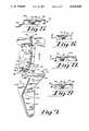
- FIG. 7is a frontal view of an unfolded tip restraint of the present invention adapted for use with an Internal Mammary Artery Bypass type of angiographic catheter;
- FIG. 8is a side cross-sectional view of the tip restraint illustrated in FIG. 7 taken along lines 8--8 of FIG. 7;
- FIG. 9is a side cross-sectional view of the tip restraint illustrated in FIG. 7 taken along lines 9--9 of FIG. 7;
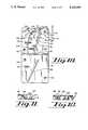
- FIG. 10is a frontal elevation view of an unfolded tip restraint of the present invention adapted for use with a left Judkins type of angiographic catheter;
- FIG. 11is a side cross-sectional view of the tip restraint illustrated in FIG. 10 taken along lines 11--11 of FIG. 10;
- FIG. 12is a side cross-sectional view of the tip restraint illustrated in FIG. 10 taken along lines 12--12 of FIG. 10;
- FIG. 13is a frontal elevation view of an unfolded tip restraint of the present invention adapted for use with a left femoral ventricular type of angiographic catheter.
- FIGS. 1-6illustrate the present invention adapted for use with a left Amplatz type of catheter designated generally herein as catheter 10.
- This type of catheter 10is typically used to visualize the left coronary artery of a patient's heart and generally includes a hub fitting 12 on the proximal end of the catheter 10 and a generally straight shaft section 14 which extends between the hub fitting 12 and a distally positioned catheter tip 16.
- the catheter tip 16 of the present embodimentincludes a primary curvature section and a distally located secondary curvature section, both of which are particularly designed to facilitate the placement of the catheter into the left ventricle of a patient's heart.
- the catheter 10is sterilely packaged in a conventional type of envelope pouch 22 consisting of a transparent polycarbonate film which is hermetically sealed to a spun polypropylene backing.
- the envelope pouch 22encloses an elongate thermoformed tray 24 which is designed to hold various shapes and sizes of angiographic catheters in the linear channel 32 during sterilization, shipping and storage.
- the tray 24includes a proximally located proximal pocket 26 having a recessed and flat base surface 27 and a hinged cover sheet 28 adapted to be folded over the proximal pocket 26.
- the hinged cover sheet 28loosely retains the hub fitting 12 of the catheter in the proximal pocket 26 of the tray 24 when the end of the cover sheet 28 is placed in a tab member 30 located near the distal of the proximal pocket 26.
- a pair of elongate and linear channels 32extend distally from the proximal pocket 26 to a larger and distally located distal pocket 36.
- the distal pocket 36includes a recessed and flat base surface 37.
- a plurality of retaining tabs 38extend across one of the linear channels 32 to retain the shaft section 14 of the catheter 10 therein.
- the location and placement of the retaining tabs 38 along the linear channel 32varies depending on the type of catheter 10 being inserted into the tray 24. As illustrated in FIGS. 1 and IA, when a Left Amplatz type of catheter is inserted into the tray 24, the shaft section 14 of the catheter 10 is preferably placed in the lower linear channel 32 and the retaining tabs 38 are evenly spaced along the outer edge of the linear channel 32.
- the upper linear channel 32is preferably used to retain the shaft section of the catheter therein.
- the retaining tabs 38are positioned adjacent to the upper linear channel 32 so that the two proximal most retaining tabs 38 are adhesively bonded from the inner edge of the upper linear channel 32 and are evenly spaced from the proximal pocket 26.
- the third retaining tab 38is adhesively bonded from the outer edge of the upper linear channel 32 and is positioned approximately one-half of the distance from the distal pocket 36 as compared to the distance between the other retaining tabs 38.
- the relative spacing of the retaining tabs 38 and the respective desired linear channel 32are chosen to provide the least amount of resistance to the removal of the catheter 10 from the tray 24 while ensuring that the catheter tip 16 will not be deformed as the catheter 10 is removed from the tray 24 and the tip restraint 40, the structure and function of which will be described more fully hereinafter.
- the tip restraint 40 of the preferred embodimentis longitudinally slidable within the distal pocket 36 of the tray 24 to allow the shaft section 14 of the catheter 10 to expand or contract during sterilization and storage of the catheter 10.
- the tip restraint 40is preferably formed from a single piece of thermoformed plastic.
- the tip restraint 40includes a base section 42 into which the catheter tip 16 is placed and a cover section 44 which assists in retaining the catheter tip 16 in the preferred preformed shape within the base section 42.
- the base section 42 and the cover section 44 of the tip restraint 40are interconnected by a hinge member 46 which is designed to move the cover section 44 away from the top surface 56 of the base section 42.
- the depth of the distal pocket 36is chosen so that when the cover section 44 of the tip restraint 40 is folded over the top surface 56 of the base section 42, the height of the tip restraint 40 will extend slightly beyond the top surface of the tray 24 to allow the sealed envelope pouch 22 to contact the cover section 44 of the tip restraint 40 to assist in retaining the tip restraint 40 in the folded condition during storage.
- the width of the tip restraint 40is chosen so that the tip restraint 40 will slide longitudinally in the distal pocket 36 and will be retained within the distal pocket 36 upon removal of the catheter 10 from the package.
- the base section 42 of the tip restraint 40includes an elongate and curved channel 48 which is shaped nearly identical to the desired preformed shape of the Left Amplatz type of catheter tip 16.
- the channel 48 of this embodimentgenerally includes a primary surface of curvature 18 and a secondary surface of curvature 20.
- the sidewalls of the channel 48 adjacent to the shaft section 14 of the catheter 10have a preferred draft angle of approximately 15°. As referred to herein, the draft angles are measured with respect to an imaginary reference line which is perpendicular to the bottom surface of the channel 48 so that a draft angle of 15° is oriented 105° from the bottom surface of the channel 48.
- the inner sidewall 50 of the channel 48is located adjacent to the primary surface of curvature 18 and includes a primary bevel 52 having a preferred draft angle of approximately 30° and a secondary bevel 53 having a preferred draft angle of approximately 45°.
- the outer sidewall 54 of the channel 48is located adjacent to the primary surface of curvature 18 and near the hinge member 46.
- the outer sidewall 54is preferably oriented perpendicular to the top surface 56 of the base section 42.
- the remaining sidewalls of the channel 48are located adjacent to the secondary surface of curvature 20 and have a preferred draft angle of approximately 15°.
- a plurality of recesses 58 on the base section 42are oriented perpendicular to the lengthwise dimension of the channel 48 and extend downwardly from the top surface 56 of the base section 42 a sufficient distance so that when the male tabs 60 from on the cover section 44 are positioned in the recesses 58, the catheter tip 16 will be retained in the channel 48 of the tip restraint 40.
- a pair of circular recesses 62are located on the base section 42 distally to the channel 48 to receive a pair of cylindrical friction tabs 64 from the cover section 44 therein. When the tip restraint 40 is folded, the friction tabs 64 are retained in the circular recesses 62.
- the cover section 44also includes a strengthening rib 65 to allow the tip restraint 40 to be manufactured using a relatively thin and lightweight thermoformed plastic material having sufficient rigidity to support the catheter tip 16 therein during sterilization and storage of the catheter 10.
- the catheter 10may expand or contract during sterilization and storage without affecting the overall shape of the preformed catheter 10.
- the tip restraint 40will slide distally in the distal pocket 36 so that the shaft section 14 of the catheter 10 is not forced out of the lower linear channel 32.
- the perpendicular outer sidewall 54 of the channel 48will prevent relaxation of the catheter tip 16 during sterilization by limiting the expansion of the primary curvature section of the catheter tip 16 so that the catheter tip does not expand beyond the outer sidewall 54 of the primary surface of curvature 18.
- the nurse or physiciandesires to remove the catheter 10 from the sterile envelope pouch 22, they will separate the proximal end of the envelope pouch 22 so that the proximal pocket 26 of the tray 24 is exposed.
- the hinged cover sheet 28is opened to allow the physician to grasp and remove the hub fitting 12 of the catheter 10 from the proximal pocket 26.
- the folded tip restraint 40will slide proximally in the distal pocket 36 until the tip restraint 40 reaches the proximal end of the distal pocket 36.
- Further pulling on the catheter 10causes the primary curvature section of the catheter tip 16 to ride up on the primary bevel 52 adjacent to the primary surface of curvature 18 in the channel 48.
- the upward pressure on the cover section 44 caused by the catheter tip 16releases the friction tabs 64 from the circular recesses 62 and the design of the hinge means 46 will open the tip restraint 40 to release the catheter tip 16 from the channel 48.
- the hinge means 46opens the tip restraint 40, the catheter tip 16 will ride up on the secondary bevel 53 and completely release from the tip restraint 40 without being deformed.
- FIGS. 7-9Another embodiment of the tip restraint 70 of the present invention is illustrated in FIGS. 7-9.
- the tip restraint 70 of this embodimentis particularly adapted for use with an internal mammary artery bypass type of angiographic catheter.
- This type of catheter 72is designed for the visualization of the coronary artery in the heart of a patient who has previously undergone bypass surgery with an internal mammary artery graft.
- This catheter 72includes a hub member and shaft section similar to the hub fitting 12 and shaft section 14 of the catheter 10 illustrated in FIG. 1 and described above with respect to the preferred embodiment.
- the tip restraint 70 of the present embodimentis designed for use in the tray 24 and envelope pouch 22 described above and generally includes an elongate base section 74 which is hingedly connected to a cover section 76 by a hinge member 78.
- the base section 74 of the present embodimentincludes an elongate channel 80 having a gradually curved first section 82 and a second section 84 having a smaller radius of curvature.
- the sidewalls of the channel 80 of this embodimentinclude preferred draft angles similar to the preferred draft angles described above with respect to the preferred embodiment.
- the sidewalls adjacent to the first section 82 of the channel 80have a preferred draft angle of approximately 15°.
- the outer sidewall 86 of the second section 84is oriented perpendicular to the top surface 88 of the base section 74 so that the catheter tip 90 will not be forced out of the channel 80 during sterilization or storage of the present catheter 72.
- the inner sidewall 92 of the second section 84includes first and second bevel sections, 94 and 96 respectively.
- the first and second bevel sections 94 and 96have a preferred draft angle of approximately 30° to facilitate the removal of the catheter tip 90 from the tip restraint 70 when the user desires to remove the catheter 72 from the catheter package as described above.
- a plurality of female recesses 98are oriented perpendicular to the channel 80 on the base section 74 of the tip restraint 70.
- the recesses 98extend downwardly from the top surface 88 of the base section 74 a sufficient distance to retain the catheter tip 90 in the channel 80 when the male tabs 100 from the cover section 76 are inserted into the female recesses 98.
- a single circular recess 104is positioned near the hinge member 78 of the present embodiment to receive a cylindrical friction tab 106 from the cover section 76 therein when the tip restraint 70 is folded.
- the cover section 76includes a strengthening rib 108 thereon. The rib 108 extends nearly the entire longitudinal length of the cover section 76 to allow the tip restraint 70 of the present embodiment to be manufactured using a relatively thin and lightweight thermoformed plastic material.
- the tip restraint 70will slide only distally or proximally within the distal pocket of the tray when the shaft section of the catheter 72 expands or contracts.
- the userdesires to remove the catheter 72 from the envelope pouch described above, they will separate the proximal end of the envelope pouch so that the proximal pocket of the elongate tray is exposed.
- the hinged cover sheetis removed from the proximal pocket and the hub fitting of the catheter 72 is grasped and removed from the proximal pocket of the tray.
- the tip restraint 70will be pulled proximally in the distal pocket of the tray until the tip restraint 70 reaches the proximal end of the distal pocket. Once the tip restraint 70 reaches the proximal end of the distal pocket, further pulling on the catheter 72 will cause the proximal section of the catheter tip 90 to straighten slightly. The distal section of the catheter tip 90 will then ride up the first and second beveled sections, 94 and 96 of the tip restraint 70. As the catheter tip 90 rides up the first and second beveled sections, 94 and 96, the male tab 100 is moved from the female recess 98 and the friction tab 106 is released from the circular recess 104.
- the design of the hinge member 78will then cause the cover section 76 to move further from the top surface 88 of the base section 74 to completely release the catheter tip 90 from the tip restraint 70 and allow the catheter 72 to be removed from the package without causing permanent deformation of the catheter tip 90.
- FIGS. 10-12Another form of the tip restraint 110 of the present invention is illustrated in FIGS. 10-12.
- the tip restraint 110 of this embodimentis particularly adapted for use with a Left Judkins type of angiographic catheter referred to herein generally as catheter 112.
- catheter 112This type of angiographic catheter is typically the catheter of choice for the visualization of the coronary arteries in most patients.
- catheter 112includes a hub member (not shown) and a shaft section 113 similar to the hub fitting 12 and shaft section 14 of the catheter 10 illustrated in FIGS. 1 and 1A and described above with respect to the preferred embodiment of the present invention.
- the tip restraint 110 of the present embodimentis designed for use in the tray 24 and envelope pouch 22 described above with respect to the preferred embodiment.
- the tip restraint 110generally includes a base section 114 which is hingedly connected to a cover section 116 by a hinge member 118.
- the base section 114 of the present embodimentincludes an elongate and recessed channel 120 having a relatively short first section 122 to retain the distal end of the shaft section 113 and the proximal end of the catheter tip 124 therein.
- the second section 126 of the channel 120consists of an enlarged and generally oblong recess having a flat interior surface 137 and a circumferential sidewall 128 to releasably retain the distal end of the catheter tip 124 therein.
- the sidewalls of the first section 122 of the channel 120include preferred draft angles of approximately 15°.
- the distal side of the circumferential sidewall 128is oriented perpendicular to the interior surface 127 of the second section 126 so that the catheter tip 124 will not be forced out of the channel 120 by relaxation of the catheter tip 124 during sterilization or storage of the present catheter 112.
- the proximal side of the second section 126includes first and second bevel sections, 132 and 134, respectively, both of which have a preferred draft angle of approximately 30°.
- the first bevel section 132is located generally along the intersection of the first section 122 and the second section 126 of the channel 120.
- the second bevel section 134is located along the proximal side of the circumferential sidewall 128.
- the first and second bevel sections, 132 and 134respectively, facilitate the removal of the catheter tip 124 from the tip restraint 110 by providing an angled surface on which the catheter tip 124 rides up to release the catheter tip 124 from the tip restraint 110 when the user desires to remove the present catheter 112 from the catheter package.
- a pair of recesses 136are oriented along the circumferential sidewall 128 of the base section 114.
- the recesses 136extend downwardly from the top surface 130 of the base section 114 so that the strengthening rib 138 and male tab 140 from the cover section 116 extend into the recesses 136 when the cover section 114 of the tip restraint 110 is folded over the top surface 130 of the base section 114.
- a pair of circular recesses 142are located on the opposite corners of the base section 114 to allow a pair of cylindrical friction tabs 144 from the cover section 116 to be releasably retained circular recesses when the cover section 114 of the tip restraint 110 is folded.
- the tip restraint 110will slide distally or proximally within the distal pocket of the tray in response to the expansion or contraction of the shaft section 113 of the catheter 112. If the catheter tip 124 of the present embodiment relaxes during sterilization or storage of the catheter 112, the distal end of the catheter tip 124 will press against the proximal side of the circumferential sidewall 128 to retain the catheter tip 124 in the desired preformed shape.
- the userdesires to remove the catheter 112 from the envelope pouch, they will separate the proximal end of the envelope pouch so that the proximal pocket of the elongate tray is exposed.
- the hinged cover sheetis opened and the hub fitting of the catheter 112 is removed from the proximal pocket.
- the tip restraint 110will be moved proximally in the distal pocket of the tray until the tip restraint 110 reaches the proximal side of the distal pocket.
- continued pulling on the hub fitting of the catheter 112will cause the catheter tip 124 to temporarily deform and ride up the first bevel section 132.
- the strengthening rib 138 and male tab 140will be moved from the recesses 136.
- the friction tabs 144will be released from the circular recesses 142.
- the design of the hinge member 118will cause the tip restraint 110 to open to allow the distal end of the catheter tip 124 to ride up the second bevel section 134 without being deformed by the circumferential sidewall 128 of the tip restraint 110.
- FIG. 13A further form of the tip restraint 150 of the present invention is illustrated in FIG. 13.
- the tip restraint 150 of this embodimentis particularly adapted for use with a left femoral ventricular type of catheter referred to herein generally as catheter 152.
- catheter 152This type of catheter 152 is particularly adapted for use in visualizing the left ventricle of the heart of a patient.
- the catheter 152includes a proximal hub member (not shown) and shaft section 154 similar to the hub fitting 12 and shaft section 14 of the catheter 10 as illustrated in FIGS. 1 and 1A and described above with respect to the preferred embodiment of the present invention.
- the tip restraint 150 of the present embodimentis particularly adapted to be used in the tray 24 and envelope pouch 22 described above.
- the tip restraint 150generally includes a base section 156 which is hingedly connected to a cover section 158 by a hinge member 160.
- the base section 156 of the present embodimentincludes an elongate and recessed channel 162 having a relatively long and slightly curved first section 164 which is adapted to retain the distal end of the shaft section 154 of the catheter 152 and the proximal end of the catheter tip 166 therein.
- the second section 168 of the channel 162consists of an enlarged and generally oblong recess having a flat interior surface 169 and a circumferentially extending sidewall 170 to releasably retain the distal end of the catheter tip 166 therein.
- the sidewalls of the first section 164 of the channel 162include preferred draft angles of approximately 15°.
- the distal side of the circumferentially extending sidewall 170is oriented perpendicular to the interior surface 169 of the second section 168 so that the catheter tip 166 of the catheter 152 will not be forced out of the channel 162 by the relaxation of the catheter tip 166 during sterilization or storage of the catheter 152.
- the proximal side of the second section 162includes first and second bevel sections 172 and 174, respectively, both of which have a preferred draft angle of approximately 30°.
- the first bevel section 172is preferably oriented perpendicular to the distal end of the catheter tip 166.
- the second bevel section 174is oriented generally perpendicular to the first bevel section 172 along the proximal side of the circumferentially extending sidewall 170.
- the first and second bevel sections, 172 and 174respectively, facilitate the removal of the catheter tip 166 from the tip restraint 150 by providing an angled surface on which the catheter tip 166 is able to ride up when the user desires to remove the catheter 152 from the package.
- a pair of recesses 176extend inwardly from the top surface 178 of the base section 156 so that the strengthening rib 180 from the cover section 158 extends into the second section 168 of the channel 162 when the cover section 158 is folded over the base section 156.
- a pair of circular recesses 182are located adjacent to the proximal corners of the base section 156. The circular recesses 182 are oriented to retain a pair of cylindrical friction tabs 184 from the cover section 158 therein to releasably retain the cover section 158 adjacent to the top surface 178 of the base section 156 when the tip restraint 150 is folded.
- the userdesires to remove the catheter 152 of the present embodiment from the tip restraint 150, they will separate the envelope pouch as described above and begin removing the hub fitting of the catheter from the proximal pocket of the tray.
- the tip restraint 150will be pulled proximally in the distal pocket of the tray until the tip restraint 150 reaches the proximal end of the distal pocket.
- Continued pulling on the catheter 152will cause the shaft section 154 of the catheter 152 to straighten and begin to leave the first section 164 of the channel 162.
Landscapes
- Health & Medical Sciences (AREA)
- Life Sciences & Earth Sciences (AREA)
- Biophysics (AREA)
- Pulmonology (AREA)
- Engineering & Computer Science (AREA)
- Anesthesiology (AREA)
- Biomedical Technology (AREA)
- Heart & Thoracic Surgery (AREA)
- Hematology (AREA)
- Animal Behavior & Ethology (AREA)
- General Health & Medical Sciences (AREA)
- Public Health (AREA)
- Veterinary Medicine (AREA)
- Media Introduction/Drainage Providing Device (AREA)
- Infusion, Injection, And Reservoir Apparatuses (AREA)
Abstract
Description
Claims (19)
Priority Applications (1)
| Application Number | Priority Date | Filing Date | Title |
|---|---|---|---|
| US07/463,092US5165540A (en) | 1990-01-10 | 1990-01-10 | Angiographic catheter package |
Applications Claiming Priority (1)
| Application Number | Priority Date | Filing Date | Title |
|---|---|---|---|
| US07/463,092US5165540A (en) | 1990-01-10 | 1990-01-10 | Angiographic catheter package |
Publications (1)
| Publication Number | Publication Date |
|---|---|
| US5165540Atrue US5165540A (en) | 1992-11-24 |
Family
ID=23838828
Family Applications (1)
| Application Number | Title | Priority Date | Filing Date |
|---|---|---|---|
| US07/463,092Expired - LifetimeUS5165540A (en) | 1990-01-10 | 1990-01-10 | Angiographic catheter package |
Country Status (1)
| Country | Link |
|---|---|
| US (1) | US5165540A (en) |
Cited By (36)
| Publication number | Priority date | Publication date | Assignee | Title |
|---|---|---|---|---|
| US5284244A (en)* | 1992-08-31 | 1994-02-08 | Ethicon, Inc. | Sterile package for surgical instruments |
| US5322163A (en)* | 1993-06-09 | 1994-06-21 | Plastofilm Industries, Inc. | Catheter tray package with lockable insert |
| US5353929A (en)* | 1993-04-19 | 1994-10-11 | United States Surgical Corporation | Package for surgical instrument |
| US5353922A (en)* | 1992-01-02 | 1994-10-11 | United States Surgical Corporation | Retainer for a combined surgical needle-suture device possessing a needle shield with needle tip stop feature |
| US5372254A (en)* | 1994-01-27 | 1994-12-13 | The Kendall Company | Catheter package and delivery system |
| US5386908A (en)* | 1993-03-25 | 1995-02-07 | United States Surgical Corporation | Package for endoscopic suture system |
| US5392918A (en)* | 1993-10-04 | 1995-02-28 | Kensey Nash Corporation | Sterile packaging including a tray and a holder for a intravascular guide-wire and a vascular puncture closure system |
| US5497601A (en)* | 1994-08-19 | 1996-03-12 | Cordis Corporation | Packaging having discrete retainers for a medical catheter and method |
| US5607055A (en)* | 1995-03-14 | 1997-03-04 | Mallinckrodt Medical, Inc. | Vacuum package for flexible products |
| US5848691A (en)* | 1997-07-07 | 1998-12-15 | Wilson-Cook Medical Inc. | Package for sphincterotome or catheter including structure maintaining shape of distal tip |
| US5947890A (en)* | 1997-09-19 | 1999-09-07 | Spencer; Robert H. | Apparatus and improved method for safely dispensing and delivering liquid radiation for intraluminal radiation therapy |
| US5947296A (en)* | 1997-10-30 | 1999-09-07 | Schneider/Namic | Multipack package |
| US6009998A (en)* | 1997-05-05 | 2000-01-04 | Flour City Packaging Corporation | Cardboard package for holding catheters |
| WO2002045785A1 (en)* | 2000-12-06 | 2002-06-13 | Boston Scientific Limited | Holding device for use with catheter packaging |
| WO2002013715A3 (en)* | 2000-08-15 | 2002-06-20 | Scimed Life Systems Inc | Medical instrument container |
| USD498671S1 (en) | 2002-04-30 | 2004-11-23 | Astra Tech Ab | Catheter package |
| USD503335S1 (en)* | 2003-10-07 | 2005-03-29 | Astra Tech Ab | Catheter package |
| US20050194276A1 (en)* | 2004-03-05 | 2005-09-08 | Lubs Jason M. | Packaging for elongate medical devices and methods of manufacture and use thereof |
| US20050199521A1 (en)* | 2004-03-15 | 2005-09-15 | Hollister Incorporated | Tear open package for hydrophilic-coated catheter |
| US20070197998A1 (en)* | 2004-03-31 | 2007-08-23 | Teruma Kabushiki Kaisha | Catheter package |
| US20070289887A1 (en)* | 2006-06-08 | 2007-12-20 | Michael Murray | Catheter product package and method of forming same |
| US20080050084A1 (en)* | 2006-08-25 | 2008-02-28 | Sjodin Chad J | Cable management system with twist latch |
| US20080087795A1 (en)* | 2006-10-12 | 2008-04-17 | The Cleveland Clinic Foundation | Apparatus and method of molding an endotracheal tube for tracheal intubation |
| US20080200907A1 (en)* | 2004-07-16 | 2008-08-21 | Astra Tech Ab | Folded Catheter Assembly With Adhesive Grip |
| US20100106161A1 (en)* | 2008-10-23 | 2010-04-29 | Marwan Tabbara | Surgical methods, devices, and kits |
| US8523843B2 (en) | 2007-11-19 | 2013-09-03 | Hollister Incorporated | Vapor hydrated catheter assembly and method of making same |
| US8662306B2 (en) | 2012-04-04 | 2014-03-04 | Cook Medical Technologies Llc | Universal catheter tray assembly |
| US20150122681A1 (en)* | 2013-11-04 | 2015-05-07 | Ethicon, Inc. | Multi-component packages for medical devices |
| US9192741B1 (en) | 2014-06-06 | 2015-11-24 | Sasan Najibi | Catheter and wire holding device |
| USD747184S1 (en)* | 2013-03-14 | 2016-01-12 | Hollister Incorporated | Compact catheter package |
| US9757222B2 (en)* | 2015-09-28 | 2017-09-12 | Howmedica Osteonics Corp. | Snapback card implant package |
| US20170290634A1 (en)* | 2016-04-07 | 2017-10-12 | Ethicon, Inc. | Containment sleeves for packages containing medical devices |
| USD816501S1 (en) | 2015-08-18 | 2018-05-01 | Baylis Medical Company Inc. | Medical device packaging tray |
| JP2020078571A (en)* | 2014-11-06 | 2020-05-28 | ファジェネシス リミテッドPhagenesis Limited | Catheter for treating dysphagia |
| US11478320B2 (en)* | 2015-08-06 | 2022-10-25 | Jacobs Emerging Technologies, Llc | Medical device holder |
| GB2623432A (en)* | 2022-10-14 | 2024-04-17 | Gyrus Medical Ltd | Medical device sterile barrier packaging system |
Citations (23)
| Publication number | Priority date | Publication date | Assignee | Title |
|---|---|---|---|---|
| US3035691A (en)* | 1960-09-19 | 1962-05-22 | Davol Rubber Co | Package for sterile articles |
| US3104172A (en)* | 1961-10-06 | 1963-09-17 | Globe Ind Inc | Packaged comestible |
| US3338401A (en)* | 1964-12-07 | 1967-08-29 | Ethicon Inc | Molded suture package |
| US3606001A (en)* | 1968-06-26 | 1971-09-20 | Sherwood Medical Ind Inc | Cardiac catheter package |
| US3612038A (en)* | 1969-02-03 | 1971-10-12 | Becton Dickinson Co | Preformable catheter package assembly and method of preforming |
| US3633758A (en)* | 1970-01-09 | 1972-01-11 | North American Instr Corp | Catheter storage rack |
| CA961452A (en)* | 1970-08-24 | 1975-01-21 | Joseph Cooper | Transparent reusable package |
| US3910410A (en)* | 1974-03-19 | 1975-10-07 | Continental Can Co | Resealable package |
| US3972418A (en)* | 1974-11-25 | 1976-08-03 | Ethicon, Inc. | Molded suture package |
| US3983996A (en)* | 1975-10-06 | 1976-10-05 | Hendren Iii William Hardy | Instrument holder |
| US4005776A (en)* | 1975-05-02 | 1977-02-01 | Plastofilm Industries, Inc. | Package for oral thermometer, catheter or the like |
| US4019633A (en)* | 1975-07-18 | 1977-04-26 | Alza Corporation | Cartoned medical instrument package |
| USRE29343E (en)* | 1972-07-13 | 1977-08-09 | Method for forming and sterilizing catheters | |
| US4230115A (en)* | 1978-10-20 | 1980-10-28 | Illinois Tool Works Inc. | Catheterization unit |
| US4256225A (en)* | 1979-07-30 | 1981-03-17 | Jackson Frank W | Fiberoptic endoscope accessory instrument storage case |
| US4262800A (en)* | 1979-08-09 | 1981-04-21 | Keb Industries | Sterilizable holder for fiber optic surgical unit or the like |
| US4332322A (en)* | 1980-09-02 | 1982-06-01 | Champion International Corporation | Folder to hold coil of plastic tubing with clamp and fittings |
| US4366901A (en)* | 1981-02-02 | 1983-01-04 | Medtronic, Inc. | In situ rehydrating in sterile packages |
| US4779727A (en)* | 1987-11-25 | 1988-10-25 | Mallinckrodt, Inc. | Catheter packaging system |
| US4807747A (en)* | 1987-09-16 | 1989-02-28 | Champion Spark Plug Company | Package structure for spark plugs |
| US4823167A (en)* | 1986-12-16 | 1989-04-18 | Baxter International Inc. | Catheter calibration device |
| US4923061A (en)* | 1986-07-30 | 1990-05-08 | C. R. Bard, Inc. | Catheter curve retention device |
| US4925448A (en)* | 1988-03-30 | 1990-05-15 | The Cleveland Clinic Foundation | Catheter package |
- 1990
- 1990-01-10USUS07/463,092patent/US5165540A/ennot_activeExpired - Lifetime
Patent Citations (23)
| Publication number | Priority date | Publication date | Assignee | Title |
|---|---|---|---|---|
| US3035691A (en)* | 1960-09-19 | 1962-05-22 | Davol Rubber Co | Package for sterile articles |
| US3104172A (en)* | 1961-10-06 | 1963-09-17 | Globe Ind Inc | Packaged comestible |
| US3338401A (en)* | 1964-12-07 | 1967-08-29 | Ethicon Inc | Molded suture package |
| US3606001A (en)* | 1968-06-26 | 1971-09-20 | Sherwood Medical Ind Inc | Cardiac catheter package |
| US3612038A (en)* | 1969-02-03 | 1971-10-12 | Becton Dickinson Co | Preformable catheter package assembly and method of preforming |
| US3633758A (en)* | 1970-01-09 | 1972-01-11 | North American Instr Corp | Catheter storage rack |
| CA961452A (en)* | 1970-08-24 | 1975-01-21 | Joseph Cooper | Transparent reusable package |
| USRE29343E (en)* | 1972-07-13 | 1977-08-09 | Method for forming and sterilizing catheters | |
| US3910410A (en)* | 1974-03-19 | 1975-10-07 | Continental Can Co | Resealable package |
| US3972418A (en)* | 1974-11-25 | 1976-08-03 | Ethicon, Inc. | Molded suture package |
| US4005776A (en)* | 1975-05-02 | 1977-02-01 | Plastofilm Industries, Inc. | Package for oral thermometer, catheter or the like |
| US4019633A (en)* | 1975-07-18 | 1977-04-26 | Alza Corporation | Cartoned medical instrument package |
| US3983996A (en)* | 1975-10-06 | 1976-10-05 | Hendren Iii William Hardy | Instrument holder |
| US4230115A (en)* | 1978-10-20 | 1980-10-28 | Illinois Tool Works Inc. | Catheterization unit |
| US4256225A (en)* | 1979-07-30 | 1981-03-17 | Jackson Frank W | Fiberoptic endoscope accessory instrument storage case |
| US4262800A (en)* | 1979-08-09 | 1981-04-21 | Keb Industries | Sterilizable holder for fiber optic surgical unit or the like |
| US4332322A (en)* | 1980-09-02 | 1982-06-01 | Champion International Corporation | Folder to hold coil of plastic tubing with clamp and fittings |
| US4366901A (en)* | 1981-02-02 | 1983-01-04 | Medtronic, Inc. | In situ rehydrating in sterile packages |
| US4923061A (en)* | 1986-07-30 | 1990-05-08 | C. R. Bard, Inc. | Catheter curve retention device |
| US4823167A (en)* | 1986-12-16 | 1989-04-18 | Baxter International Inc. | Catheter calibration device |
| US4807747A (en)* | 1987-09-16 | 1989-02-28 | Champion Spark Plug Company | Package structure for spark plugs |
| US4779727A (en)* | 1987-11-25 | 1988-10-25 | Mallinckrodt, Inc. | Catheter packaging system |
| US4925448A (en)* | 1988-03-30 | 1990-05-15 | The Cleveland Clinic Foundation | Catheter package |
Cited By (62)
| Publication number | Priority date | Publication date | Assignee | Title |
|---|---|---|---|---|
| US5353922A (en)* | 1992-01-02 | 1994-10-11 | United States Surgical Corporation | Retainer for a combined surgical needle-suture device possessing a needle shield with needle tip stop feature |
| US5284244A (en)* | 1992-08-31 | 1994-02-08 | Ethicon, Inc. | Sterile package for surgical instruments |
| US5386908A (en)* | 1993-03-25 | 1995-02-07 | United States Surgical Corporation | Package for endoscopic suture system |
| US5353929A (en)* | 1993-04-19 | 1994-10-11 | United States Surgical Corporation | Package for surgical instrument |
| US5322163A (en)* | 1993-06-09 | 1994-06-21 | Plastofilm Industries, Inc. | Catheter tray package with lockable insert |
| US5392918A (en)* | 1993-10-04 | 1995-02-28 | Kensey Nash Corporation | Sterile packaging including a tray and a holder for a intravascular guide-wire and a vascular puncture closure system |
| US5372254A (en)* | 1994-01-27 | 1994-12-13 | The Kendall Company | Catheter package and delivery system |
| US5497601A (en)* | 1994-08-19 | 1996-03-12 | Cordis Corporation | Packaging having discrete retainers for a medical catheter and method |
| US5607055A (en)* | 1995-03-14 | 1997-03-04 | Mallinckrodt Medical, Inc. | Vacuum package for flexible products |
| US6009998A (en)* | 1997-05-05 | 2000-01-04 | Flour City Packaging Corporation | Cardboard package for holding catheters |
| WO1999002099A2 (en) | 1997-07-07 | 1999-01-21 | Wilson-Cook Medical Inc. | Shape forming/maintaining package for sphincterotome |
| WO1999002099A3 (en)* | 1997-07-07 | 1999-04-01 | Wilson Cook Medical Inc | Shape forming/maintaining package for sphincterotome |
| US5848691A (en)* | 1997-07-07 | 1998-12-15 | Wilson-Cook Medical Inc. | Package for sphincterotome or catheter including structure maintaining shape of distal tip |
| US5947890A (en)* | 1997-09-19 | 1999-09-07 | Spencer; Robert H. | Apparatus and improved method for safely dispensing and delivering liquid radiation for intraluminal radiation therapy |
| US5947296A (en)* | 1997-10-30 | 1999-09-07 | Schneider/Namic | Multipack package |
| WO2002013715A3 (en)* | 2000-08-15 | 2002-06-20 | Scimed Life Systems Inc | Medical instrument container |
| WO2002045785A1 (en)* | 2000-12-06 | 2002-06-13 | Boston Scientific Limited | Holding device for use with catheter packaging |
| US6892881B2 (en) | 2000-12-06 | 2005-05-17 | Scimed Life Systems, Inc. | Holding device for use with catheter packaging |
| USD499643S1 (en) | 2002-04-30 | 2004-12-14 | Astra Tech Ab | Catheter package with catheter |
| USD499016S1 (en) | 2002-04-30 | 2004-11-30 | Astra Tech Ab | Catheter package |
| USD499017S1 (en) | 2002-04-30 | 2004-11-30 | Astra Tech Ab | Catheter package with catheter |
| USD499335S1 (en) | 2002-04-30 | 2004-12-07 | Astra Tech Ab | Catheter package with catheter |
| USD498672S1 (en) | 2002-04-30 | 2004-11-23 | Astra Tech Ab | Catheter package |
| USD505067S1 (en)* | 2002-04-30 | 2005-05-17 | Astra Tech Ab | Catheter package with catheter |
| USD498671S1 (en) | 2002-04-30 | 2004-11-23 | Astra Tech Ab | Catheter package |
| USD503335S1 (en)* | 2003-10-07 | 2005-03-29 | Astra Tech Ab | Catheter package |
| US20050194276A1 (en)* | 2004-03-05 | 2005-09-08 | Lubs Jason M. | Packaging for elongate medical devices and methods of manufacture and use thereof |
| US7328794B2 (en) | 2004-03-05 | 2008-02-12 | Boston Scientific Scimed, Inc. | Packaging for elongate medical devices and methods of manufacture and use thereof |
| US7334679B2 (en) | 2004-03-15 | 2008-02-26 | Hollister Incorporated | Tear open package for hydrophilic-coated catheter |
| US20050199521A1 (en)* | 2004-03-15 | 2005-09-15 | Hollister Incorporated | Tear open package for hydrophilic-coated catheter |
| US20070197998A1 (en)* | 2004-03-31 | 2007-08-23 | Teruma Kabushiki Kaisha | Catheter package |
| US7743918B2 (en)* | 2004-03-31 | 2010-06-29 | Terumo Kabushiki Kaisha | Catheter package |
| US20080200907A1 (en)* | 2004-07-16 | 2008-08-21 | Astra Tech Ab | Folded Catheter Assembly With Adhesive Grip |
| US8052673B2 (en)* | 2004-07-16 | 2011-11-08 | Astra Tech Ab | Folded catheter assembly with adhesive grip |
| US8356457B2 (en) | 2006-06-08 | 2013-01-22 | Hollister Incorporated | Catheter product package and method of forming same |
| US7770726B2 (en) | 2006-06-08 | 2010-08-10 | Hollister Incorporated | Catheter product package and method of forming same |
| US8051981B2 (en) | 2006-06-08 | 2011-11-08 | Hollister Incorporated | Catheter product package and method of forming same |
| US8919553B2 (en) | 2006-06-08 | 2014-12-30 | Hollister Incorporated | Catheter product package and method of forming same |
| US20070289887A1 (en)* | 2006-06-08 | 2007-12-20 | Michael Murray | Catheter product package and method of forming same |
| US20080050084A1 (en)* | 2006-08-25 | 2008-02-28 | Sjodin Chad J | Cable management system with twist latch |
| US20080087795A1 (en)* | 2006-10-12 | 2008-04-17 | The Cleveland Clinic Foundation | Apparatus and method of molding an endotracheal tube for tracheal intubation |
| US8343408B2 (en)* | 2006-10-12 | 2013-01-01 | Smith Michael P | Method of molding an endotracheal tube for tracheal intubation |
| US8523843B2 (en) | 2007-11-19 | 2013-09-03 | Hollister Incorporated | Vapor hydrated catheter assembly and method of making same |
| US20100106161A1 (en)* | 2008-10-23 | 2010-04-29 | Marwan Tabbara | Surgical methods, devices, and kits |
| US8662306B2 (en) | 2012-04-04 | 2014-03-04 | Cook Medical Technologies Llc | Universal catheter tray assembly |
| USD747184S1 (en)* | 2013-03-14 | 2016-01-12 | Hollister Incorporated | Compact catheter package |
| US20150122681A1 (en)* | 2013-11-04 | 2015-05-07 | Ethicon, Inc. | Multi-component packages for medical devices |
| US9265578B2 (en)* | 2013-11-04 | 2016-02-23 | Ethicon, Llc | Multi-component packages for medical devices |
| JP2016539759A (en)* | 2013-11-04 | 2016-12-22 | エシコン・エルエルシーEthicon, LLC | Multi-component package for medical devices |
| AU2014342636B2 (en)* | 2013-11-04 | 2019-03-07 | Ethicon, Llc | Multi-component packages for medical devices |
| RU2695559C2 (en)* | 2013-11-04 | 2019-07-24 | ЭТИКОН ЭлЭлСи | Packaging for medical device (versions) |
| US9192741B1 (en) | 2014-06-06 | 2015-11-24 | Sasan Najibi | Catheter and wire holding device |
| WO2015188102A1 (en)* | 2014-06-06 | 2015-12-10 | Najibi Sasan | Catheter holding device |
| JP2020078571A (en)* | 2014-11-06 | 2020-05-28 | ファジェネシス リミテッドPhagenesis Limited | Catheter for treating dysphagia |
| JP6990933B2 (en) | 2014-11-06 | 2022-02-03 | ファジェネシス リミテッド | Catheter for treating dysphagia |
| US11478320B2 (en)* | 2015-08-06 | 2022-10-25 | Jacobs Emerging Technologies, Llc | Medical device holder |
| USD816501S1 (en) | 2015-08-18 | 2018-05-01 | Baylis Medical Company Inc. | Medical device packaging tray |
| US9757222B2 (en)* | 2015-09-28 | 2017-09-12 | Howmedica Osteonics Corp. | Snapback card implant package |
| US10485627B2 (en)* | 2016-04-07 | 2019-11-26 | Ethicon, Inc. | Containment sleeves for packages containing medical devices |
| US20170290634A1 (en)* | 2016-04-07 | 2017-10-12 | Ethicon, Inc. | Containment sleeves for packages containing medical devices |
| GB2623432A (en)* | 2022-10-14 | 2024-04-17 | Gyrus Medical Ltd | Medical device sterile barrier packaging system |
| GB2623432B (en)* | 2022-10-14 | 2025-09-03 | Gyrus Medical Ltd | Medical device sterile barrier packaging system |
Similar Documents
| Publication | Publication Date | Title |
|---|---|---|
| US5165540A (en) | Angiographic catheter package | |
| US3853130A (en) | Sterile handling catheter assemblies | |
| US5392918A (en) | Sterile packaging including a tray and a holder for a intravascular guide-wire and a vascular puncture closure system | |
| US7743918B2 (en) | Catheter package | |
| US11083564B2 (en) | Methods and systems for delivering a filled prosthetic bladder into a surgical cavity | |
| EP3193999B1 (en) | Sterile molded dispenser | |
| US5375717A (en) | Foldable package for endoscopic components and the like | |
| US4379506A (en) | Catheter assembly | |
| JP2894936B2 (en) | Packages for elongated medical devices | |
| EP2916901B1 (en) | Intermittent catheter assembly | |
| US5842567A (en) | Quick release package | |
| JP3272089B2 (en) | Package for mesh onlay and mounting mesh plug | |
| US4923061A (en) | Catheter curve retention device | |
| US5116327A (en) | Hysterectomy drain appliance | |
| US20080319387A1 (en) | Method and Apparatus for Inserting a Catheter Device | |
| US3166189A (en) | Catheterization package | |
| US5322163A (en) | Catheter tray package with lockable insert | |
| JP3179117B2 (en) | Catheter package | |
| JPH02504002A (en) | ophthalmological instruments | |
| US20230001142A1 (en) | Systems and Methods for Accessing Small Arteries for Conveying Catheters to Target Vessels | |
| CN115998362A (en) | Device to assist with umbilical catheter placement in premature and newborn infants | |
| JP5501013B2 (en) | Medical tube connector and medical tube package | |
| JP4933059B2 (en) | Package | |
| CA3170580A1 (en) | Systems and methods for accessing small arteries for conveying catheters to target vessels | |
| BR112021005690B1 (en) | SYSTEMS FOR DELIVERING A FILLED PROSTHETIC BLADDER INTO A SURGICAL CAVITY |
Legal Events
| Date | Code | Title | Description |
|---|---|---|---|
| AS | Assignment | Owner name:SHERWOOD MEDICAL COMPANY, A CORP. OF DELAWARE, MIC Free format text:ASSIGNMENT OF ASSIGNORS INTEREST.;ASSIGNOR:FORNEY, LEROY S.;REEL/FRAME:005285/0979 Effective date:19900110 | |
| STCF | Information on status: patent grant | Free format text:PATENTED CASE | |
| AS | Assignment | Owner name:NAMIC U.S.A. CORPORATION, NEW YORK Free format text:ASSIGNMENT OF ASSIGNORS INTEREST;ASSIGNOR:SHERWOOD MEDICAL COMPANY;REEL/FRAME:006650/0096 Effective date:19930215 | |
| FEPP | Fee payment procedure | Free format text:PAYOR NUMBER ASSIGNED (ORIGINAL EVENT CODE: ASPN); ENTITY STATUS OF PATENT OWNER: LARGE ENTITY | |
| FEPP | Fee payment procedure | Free format text:PAT HOLDER CLAIMS SMALL ENTITY STATUS - SMALL BUSINESS (ORIGINAL EVENT CODE: SM02); ENTITY STATUS OF PATENT OWNER: LARGE ENTITY Free format text:PAYER NUMBER DE-ASSIGNED (ORIGINAL EVENT CODE: RMPN); ENTITY STATUS OF PATENT OWNER: LARGE ENTITY Free format text:PAYOR NUMBER ASSIGNED (ORIGINAL EVENT CODE: ASPN); ENTITY STATUS OF PATENT OWNER: LARGE ENTITY | |
| FPAY | Fee payment | Year of fee payment:4 | |
| FEPP | Fee payment procedure | Free format text:PAYER NUMBER DE-ASSIGNED (ORIGINAL EVENT CODE: RMPN); ENTITY STATUS OF PATENT OWNER: LARGE ENTITY Free format text:PAYOR NUMBER ASSIGNED (ORIGINAL EVENT CODE: ASPN); ENTITY STATUS OF PATENT OWNER: LARGE ENTITY | |
| AS | Assignment | Owner name:SCHNEIDER/NAMIC, NEW YORK Free format text:CHANGE OF NAME;ASSIGNOR:NAMIC U.S.A. CORPORATION;REEL/FRAME:008535/0446 Effective date:19961218 | |
| FEPP | Fee payment procedure | Free format text:PAT HLDR NO LONGER CLAIMS SMALL ENT STAT AS SMALL BUSINESS (ORIGINAL EVENT CODE: LSM2); ENTITY STATUS OF PATENT OWNER: LARGE ENTITY | |
| FPAY | Fee payment | Year of fee payment:8 | |
| FPAY | Fee payment | Year of fee payment:12 |