US5165145A - Hinge for use with portable electronic apparatus - Google Patents
Hinge for use with portable electronic apparatusDownload PDFInfo
- Publication number
- US5165145A US5165145AUS07/589,141US58914190AUS5165145AUS 5165145 AUS5165145 AUS 5165145AUS 58914190 AUS58914190 AUS 58914190AUS 5165145 AUS5165145 AUS 5165145A
- Authority
- US
- United States
- Prior art keywords
- friction
- shaft
- character display
- members
- brake assembly
- Prior art date
- Legal status (The legal status is an assumption and is not a legal conclusion. Google has not performed a legal analysis and makes no representation as to the accuracy of the status listed.)
- Expired - Fee Related
Links
Images


Classifications
- G—PHYSICS
- G06—COMPUTING OR CALCULATING; COUNTING
- G06F—ELECTRIC DIGITAL DATA PROCESSING
- G06F1/00—Details not covered by groups G06F3/00 - G06F13/00 and G06F21/00
- G06F1/16—Constructional details or arrangements
- G06F1/1613—Constructional details or arrangements for portable computers
- G06F1/1633—Constructional details or arrangements of portable computers not specific to the type of enclosures covered by groups G06F1/1615 - G06F1/1626
- G06F1/1684—Constructional details or arrangements related to integrated I/O peripherals not covered by groups G06F1/1635 - G06F1/1675
- G06F1/1696—Constructional details or arrangements related to integrated I/O peripherals not covered by groups G06F1/1635 - G06F1/1675 the I/O peripheral being a printing or scanning device
- G—PHYSICS
- G06—COMPUTING OR CALCULATING; COUNTING
- G06F—ELECTRIC DIGITAL DATA PROCESSING
- G06F1/00—Details not covered by groups G06F3/00 - G06F13/00 and G06F21/00
- G06F1/16—Constructional details or arrangements
- G06F1/1613—Constructional details or arrangements for portable computers
- G06F1/1615—Constructional details or arrangements for portable computers with several enclosures having relative motions, each enclosure supporting at least one I/O or computing function
- G06F1/1616—Constructional details or arrangements for portable computers with several enclosures having relative motions, each enclosure supporting at least one I/O or computing function with folding flat displays, e.g. laptop computers or notebooks having a clamshell configuration, with body parts pivoting to an open position around an axis parallel to the plane they define in closed position
- G—PHYSICS
- G06—COMPUTING OR CALCULATING; COUNTING
- G06F—ELECTRIC DIGITAL DATA PROCESSING
- G06F1/00—Details not covered by groups G06F3/00 - G06F13/00 and G06F21/00
- G06F1/16—Constructional details or arrangements
- G06F1/1613—Constructional details or arrangements for portable computers
- G06F1/1633—Constructional details or arrangements of portable computers not specific to the type of enclosures covered by groups G06F1/1615 - G06F1/1626
- G06F1/1675—Miscellaneous details related to the relative movement between the different enclosures or enclosure parts
- G06F1/1681—Details related solely to hinges
- E—FIXED CONSTRUCTIONS
- E05—LOCKS; KEYS; WINDOW OR DOOR FITTINGS; SAFES
- E05D—HINGES OR SUSPENSION DEVICES FOR DOORS, WINDOWS OR WINGS
- E05D11/00—Additional features or accessories of hinges
- E05D11/08—Friction devices between relatively-movable hinge parts
- E05D11/087—Friction devices between relatively-movable hinge parts with substantially axial friction, e.g. friction disks
- E—FIXED CONSTRUCTIONS
- E05—LOCKS; KEYS; WINDOW OR DOOR FITTINGS; SAFES
- E05F—DEVICES FOR MOVING WINGS INTO OPEN OR CLOSED POSITION; CHECKS FOR WINGS; WING FITTINGS NOT OTHERWISE PROVIDED FOR, CONCERNED WITH THE FUNCTIONING OF THE WING
- E05F1/00—Closers or openers for wings, not otherwise provided for in this subclass
- E05F1/08—Closers or openers for wings, not otherwise provided for in this subclass spring-actuated, e.g. for horizontally sliding wings
- E05F1/10—Closers or openers for wings, not otherwise provided for in this subclass spring-actuated, e.g. for horizontally sliding wings for swinging wings, e.g. counterbalance
- E05F1/12—Mechanisms in the shape of hinges or pivots, operated by springs
- E05F1/1207—Mechanisms in the shape of hinges or pivots, operated by springs with a coil spring parallel with the pivot axis
- E05F1/1223—Mechanisms in the shape of hinges or pivots, operated by springs with a coil spring parallel with the pivot axis with a compression or traction spring
- E—FIXED CONSTRUCTIONS
- E05—LOCKS; KEYS; WINDOW OR DOOR FITTINGS; SAFES
- E05Y—INDEXING SCHEME ASSOCIATED WITH SUBCLASSES E05D AND E05F, RELATING TO CONSTRUCTION ELEMENTS, ELECTRIC CONTROL, POWER SUPPLY, POWER SIGNAL OR TRANSMISSION, USER INTERFACES, MOUNTING OR COUPLING, DETAILS, ACCESSORIES, AUXILIARY OPERATIONS NOT OTHERWISE PROVIDED FOR, APPLICATION THEREOF
- E05Y2999/00—Subject-matter not otherwise provided for in this subclass
Definitions
- the character displaymay also have a second pivot axis.
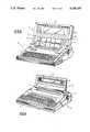
- a second pivot axisis defined by two aligned hinge mechanisms located on opposite sides of the cover member, just down from the LCD panel. The presence of the second pivot axis provides the operator with the option of either opening the display along the first pivot axis to a first viewing position when utilizing built-in printer functions in conjunction with the character display, or opening the display along the second pivot axis to a second viewing position when only utilizing the character display and not the printer.
- FIG. 1is a perspective view of a two-view position electronic typewriter made in accordance with the present invention, showing the character display in a closed position.
Landscapes
- Engineering & Computer Science (AREA)
- Computer Hardware Design (AREA)
- Theoretical Computer Science (AREA)
- Physics & Mathematics (AREA)
- Human Computer Interaction (AREA)
- General Engineering & Computer Science (AREA)
- General Physics & Mathematics (AREA)
- Mathematical Physics (AREA)
- Pivots And Pivotal Connections (AREA)
Abstract
Description
Claims (19)
Priority Applications (1)
| Application Number | Priority Date | Filing Date | Title |
|---|---|---|---|
| US07/589,141US5165145A (en) | 1990-09-27 | 1990-09-27 | Hinge for use with portable electronic apparatus |
Applications Claiming Priority (1)
| Application Number | Priority Date | Filing Date | Title |
|---|---|---|---|
| US07/589,141US5165145A (en) | 1990-09-27 | 1990-09-27 | Hinge for use with portable electronic apparatus |
Publications (1)
| Publication Number | Publication Date |
|---|---|
| US5165145Atrue US5165145A (en) | 1992-11-24 |
Family
ID=24356777
Family Applications (1)
| Application Number | Title | Priority Date | Filing Date |
|---|---|---|---|
| US07/589,141Expired - Fee RelatedUS5165145A (en) | 1990-09-27 | 1990-09-27 | Hinge for use with portable electronic apparatus |
Country Status (1)
| Country | Link |
|---|---|
| US (1) | US5165145A (en) |
Cited By (32)
| Publication number | Priority date | Publication date | Assignee | Title |
|---|---|---|---|---|
| US5507072A (en)* | 1993-11-29 | 1996-04-16 | Samsung Electronics Co., Ltd. | Hinge securement device for a portable computer |
| US5646872A (en) | 1993-01-25 | 1997-07-08 | Hitachi, Ltd. | Information processing apparatus |
| US5752293A (en)* | 1993-06-02 | 1998-05-19 | Cema Technologies, Inc. | Hinge assembly |
| GB2336018A (en)* | 1998-03-30 | 1999-10-06 | Lg Electronics Inc | Pivoting device for a flat panel display |
| US6065187A (en)* | 1998-05-14 | 2000-05-23 | Motorola, Inc. | Hinge assembly |
| US6101676A (en)* | 1998-01-27 | 2000-08-15 | Dell Usa, L.P. | Adjustable clutch hinge assembly for portable computer |
| US6125509A (en)* | 1997-12-01 | 2000-10-03 | Motorola, Inc. | Rotation dependent frictional hinge mechanism |
| US6175990B1 (en)* | 1997-10-08 | 2001-01-23 | Katoh Electrical Machinery Co., Ltd. | Hinge device |
| US6233138B1 (en)* | 1999-07-16 | 2001-05-15 | Evergreen Innovations, L.L.C. | Telescoping pivot hinge for computer display |
| US6249951B1 (en)* | 1997-05-30 | 2001-06-26 | Nec Corporation | Hinge structure for electronic apparatus |
| EP1115173A2 (en)* | 1999-11-03 | 2001-07-11 | Magcom AS | Portable radio communication device, such as a portable telephone |
| EP1246045A2 (en)* | 2001-03-07 | 2002-10-02 | Sharp Kabushiki Kaisha | Keyboard slide mechanism |
| US6504707B2 (en)* | 2000-06-14 | 2003-01-07 | International Business Machines Corporation | Portable computer |
| US6507485B2 (en) | 2001-01-04 | 2003-01-14 | Apple Computer, Inc. | Spring loaded hinge apparatus |
| US6505382B1 (en)* | 1999-05-14 | 2003-01-14 | Apple Computer, Inc. | Hinge apparatus with cam mechanism |
| US6510588B2 (en)* | 2000-05-30 | 2003-01-28 | Nokia Mobile Phones Ltd. | Turning mechanism for providing turning motion, and hinged electronic device |
| KR100391379B1 (en)* | 2001-04-04 | 2003-07-16 | 주식회사 엠투시스 | Cover hinge mechanism of cellular phone |
| US20040055114A1 (en)* | 2002-09-19 | 2004-03-25 | Lu Sheng-Nan | Hinge assembly for supporting LCD display panel |
| US6741456B2 (en)* | 2001-04-18 | 2004-05-25 | Hewlett-Packard Development Company, L.P. | System and method for pivotably securing display housing to computer system |
| WO2003107574A3 (en)* | 2002-06-13 | 2004-07-29 | Motorola Inc | Electronics devices with spring biased hinges and methods therefor |
| US6899311B1 (en) | 2003-01-22 | 2005-05-31 | Apple Computer, Inc. | Easel display arrangement |
| US20050204508A1 (en)* | 2004-03-19 | 2005-09-22 | Fih Co., Ltd. | Hinge mechanism with single hand operation |
| US20060185122A1 (en)* | 2003-08-01 | 2006-08-24 | Nhk Spring Co., Ltd. | Hinge device |
| US20060279920A1 (en)* | 2005-06-08 | 2006-12-14 | Kun-Ho Lee | Two-way auto-locking tablet PC hinge |
| US20080034540A1 (en)* | 2006-08-11 | 2008-02-14 | Hal Avery | Hinge System |
| US20100043178A1 (en)* | 2005-08-11 | 2010-02-25 | Robert Reisel | Resilient Axis Damper |
| US20100079931A1 (en)* | 2008-09-30 | 2010-04-01 | Hewlett-Packard Development Company, L.P. | Anti-oscillation device for a notebook display |
| US20110013350A1 (en)* | 2008-03-04 | 2011-01-20 | Tracy Mark S | Friction Mechanisms For Computing Devices |
| WO2011146887A1 (en)* | 2010-05-21 | 2011-11-24 | Johnson Controls Technology Company | Hinge assembly for vehicle interior trim component |
| US8516668B2 (en) | 2011-10-24 | 2013-08-27 | Venturesource Solutions, Inc. | Torque assembly and method of manufacture |
| US9348372B2 (en)* | 2014-06-13 | 2016-05-24 | Apple Inc. | Friction hinge with embedded counterbalance |
| US9778684B2 (en) | 2013-11-15 | 2017-10-03 | Hewlett-Packard Development Company, L.P. | Locking arms for computing devices |
Citations (8)
| Publication number | Priority date | Publication date | Assignee | Title |
|---|---|---|---|---|
| US1644249A (en)* | 1926-05-18 | 1927-10-04 | John H Harrison | Combined hinge and doorcheck |
| CA472975A (en)* | 1951-04-17 | M. Lane Guy | Variable friction pivots for ventilator panels | |
| US3052497A (en)* | 1960-12-19 | 1962-09-04 | Gen Motors Corp | Window regulator |
| US4571456A (en)* | 1982-10-18 | 1986-02-18 | Grid Systems Corporation | Portable computer |
| US4624434A (en)* | 1984-12-19 | 1986-11-25 | Burroughs Corporation | Stable tiltable display terminal |
| US4781422A (en)* | 1985-11-14 | 1988-11-01 | Random Corporation | Adjustable clutch mechanism |
| US4808017A (en)* | 1987-09-23 | 1989-02-28 | Smith Corona Corporation | Pivotable character display for a typewriter |
| US4859092A (en)* | 1986-11-18 | 1989-08-22 | Kabushiki Kaisha Toshiba | Portable apparatus with a mechanism for holding a display above a printer while the printer is printing data |
- 1990
- 1990-09-27USUS07/589,141patent/US5165145A/ennot_activeExpired - Fee Related
Patent Citations (9)
| Publication number | Priority date | Publication date | Assignee | Title |
|---|---|---|---|---|
| CA472975A (en)* | 1951-04-17 | M. Lane Guy | Variable friction pivots for ventilator panels | |
| US1644249A (en)* | 1926-05-18 | 1927-10-04 | John H Harrison | Combined hinge and doorcheck |
| US3052497A (en)* | 1960-12-19 | 1962-09-04 | Gen Motors Corp | Window regulator |
| US4571456A (en)* | 1982-10-18 | 1986-02-18 | Grid Systems Corporation | Portable computer |
| US4571456B1 (en)* | 1982-10-18 | 1995-08-15 | Grid Systems Corp | Portable computer |
| US4624434A (en)* | 1984-12-19 | 1986-11-25 | Burroughs Corporation | Stable tiltable display terminal |
| US4781422A (en)* | 1985-11-14 | 1988-11-01 | Random Corporation | Adjustable clutch mechanism |
| US4859092A (en)* | 1986-11-18 | 1989-08-22 | Kabushiki Kaisha Toshiba | Portable apparatus with a mechanism for holding a display above a printer while the printer is printing data |
| US4808017A (en)* | 1987-09-23 | 1989-02-28 | Smith Corona Corporation | Pivotable character display for a typewriter |
Non-Patent Citations (2)
| Title |
|---|
| Design News Magazine, dated Feb. 12, 1990, pp. 262 & 263, article "Constant-Torque Slip Clutch Supports Computer Screen" by Charles J. Murray. |
| Design News Magazine, dated Feb. 12, 1990, pp. 262 & 263, article Constant Torque Slip Clutch Supports Computer Screen by Charles J. Murray.* |
Cited By (45)
| Publication number | Priority date | Publication date | Assignee | Title |
|---|---|---|---|---|
| US5646872A (en) | 1993-01-25 | 1997-07-08 | Hitachi, Ltd. | Information processing apparatus |
| US5752293A (en)* | 1993-06-02 | 1998-05-19 | Cema Technologies, Inc. | Hinge assembly |
| US5507072A (en)* | 1993-11-29 | 1996-04-16 | Samsung Electronics Co., Ltd. | Hinge securement device for a portable computer |
| US6249951B1 (en)* | 1997-05-30 | 2001-06-26 | Nec Corporation | Hinge structure for electronic apparatus |
| US6175990B1 (en)* | 1997-10-08 | 2001-01-23 | Katoh Electrical Machinery Co., Ltd. | Hinge device |
| US6125509A (en)* | 1997-12-01 | 2000-10-03 | Motorola, Inc. | Rotation dependent frictional hinge mechanism |
| US6101676A (en)* | 1998-01-27 | 2000-08-15 | Dell Usa, L.P. | Adjustable clutch hinge assembly for portable computer |
| GB2336018A (en)* | 1998-03-30 | 1999-10-06 | Lg Electronics Inc | Pivoting device for a flat panel display |
| GB2336018B (en)* | 1998-03-30 | 2000-07-12 | Lg Electronics Inc | Pivotal rotation adjusting apparatus for flat panel display device |
| US6065187A (en)* | 1998-05-14 | 2000-05-23 | Motorola, Inc. | Hinge assembly |
| US6505382B1 (en)* | 1999-05-14 | 2003-01-14 | Apple Computer, Inc. | Hinge apparatus with cam mechanism |
| US6233138B1 (en)* | 1999-07-16 | 2001-05-15 | Evergreen Innovations, L.L.C. | Telescoping pivot hinge for computer display |
| EP1115173A2 (en)* | 1999-11-03 | 2001-07-11 | Magcom AS | Portable radio communication device, such as a portable telephone |
| US6510588B2 (en)* | 2000-05-30 | 2003-01-28 | Nokia Mobile Phones Ltd. | Turning mechanism for providing turning motion, and hinged electronic device |
| US6504707B2 (en)* | 2000-06-14 | 2003-01-07 | International Business Machines Corporation | Portable computer |
| US6507485B2 (en) | 2001-01-04 | 2003-01-14 | Apple Computer, Inc. | Spring loaded hinge apparatus |
| EP1246045A2 (en)* | 2001-03-07 | 2002-10-02 | Sharp Kabushiki Kaisha | Keyboard slide mechanism |
| KR100391379B1 (en)* | 2001-04-04 | 2003-07-16 | 주식회사 엠투시스 | Cover hinge mechanism of cellular phone |
| US20040174668A1 (en)* | 2001-04-18 | 2004-09-09 | Sellers Charles A. | System and method for pivotably securing display housing to computer system |
| US6741456B2 (en)* | 2001-04-18 | 2004-05-25 | Hewlett-Packard Development Company, L.P. | System and method for pivotably securing display housing to computer system |
| US6873522B2 (en) | 2001-04-18 | 2005-03-29 | Hewlett-Packard Development Company, L.P. | System and method for pivotably securing display housing to computer system |
| WO2003107574A3 (en)* | 2002-06-13 | 2004-07-29 | Motorola Inc | Electronics devices with spring biased hinges and methods therefor |
| US20040166890A1 (en)* | 2002-06-13 | 2004-08-26 | Ryszard Gordecki | Electronics devices with spring biased hinges and methods therefor |
| GB2405050A (en)* | 2002-06-13 | 2005-02-16 | Motorola Inc | Electronics devices with spring biased hinges and methods therefor |
| GB2405050B (en)* | 2002-06-13 | 2005-10-26 | Motorola Inc | Electronics devices with spring biased hinges and methods therefor |
| US7111362B2 (en)* | 2002-06-13 | 2006-09-26 | Motorola, Inc. | Electronics devices with spring biased hinges and methods therefor |
| US20040055114A1 (en)* | 2002-09-19 | 2004-03-25 | Lu Sheng-Nan | Hinge assembly for supporting LCD display panel |
| US6899311B1 (en) | 2003-01-22 | 2005-05-31 | Apple Computer, Inc. | Easel display arrangement |
| US20060185122A1 (en)* | 2003-08-01 | 2006-08-24 | Nhk Spring Co., Ltd. | Hinge device |
| US20050204508A1 (en)* | 2004-03-19 | 2005-09-22 | Fih Co., Ltd. | Hinge mechanism with single hand operation |
| US7124472B2 (en)* | 2004-03-19 | 2006-10-24 | Fih Co., Ltd. | Hinge mechanism with single hand operation |
| US20060279920A1 (en)* | 2005-06-08 | 2006-12-14 | Kun-Ho Lee | Two-way auto-locking tablet PC hinge |
| US20100043178A1 (en)* | 2005-08-11 | 2010-02-25 | Robert Reisel | Resilient Axis Damper |
| US20080034540A1 (en)* | 2006-08-11 | 2008-02-14 | Hal Avery | Hinge System |
| US20110013350A1 (en)* | 2008-03-04 | 2011-01-20 | Tracy Mark S | Friction Mechanisms For Computing Devices |
| US20100079931A1 (en)* | 2008-09-30 | 2010-04-01 | Hewlett-Packard Development Company, L.P. | Anti-oscillation device for a notebook display |
| US7920374B2 (en)* | 2008-09-30 | 2011-04-05 | Hewlett-Packard Development Company, L.P. | Anti-oscillation device for a notebook display |
| CN102947526A (en)* | 2010-05-21 | 2013-02-27 | 江森自控科技公司 | Articulations for vehicle interior components |
| WO2011146887A1 (en)* | 2010-05-21 | 2011-11-24 | Johnson Controls Technology Company | Hinge assembly for vehicle interior trim component |
| US20130111706A1 (en)* | 2010-05-21 | 2013-05-09 | Johnson Controls Technology Company | Hinge assembly for vehicle interior trim component |
| US8943650B2 (en)* | 2010-05-21 | 2015-02-03 | Johnson Controls Technology Company | Hinge assembly for vehicle interior trim component |
| CN102947526B (en)* | 2010-05-21 | 2016-01-27 | 江森自控科技公司 | Articulations for vehicle interior components |
| US8516668B2 (en) | 2011-10-24 | 2013-08-27 | Venturesource Solutions, Inc. | Torque assembly and method of manufacture |
| US9778684B2 (en) | 2013-11-15 | 2017-10-03 | Hewlett-Packard Development Company, L.P. | Locking arms for computing devices |
| US9348372B2 (en)* | 2014-06-13 | 2016-05-24 | Apple Inc. | Friction hinge with embedded counterbalance |
Similar Documents
| Publication | Publication Date | Title |
|---|---|---|
| US5165145A (en) | Hinge for use with portable electronic apparatus | |
| JP2740830B2 (en) | Friction hinge device | |
| US6223393B1 (en) | Redundant hinge element for a notebook computer | |
| EP0404166B1 (en) | Hinge device having mechanism for stopping movable member at open position | |
| US6510588B2 (en) | Turning mechanism for providing turning motion, and hinged electronic device | |
| US4980676A (en) | Electronic apparatus with keyboard | |
| US5109573A (en) | Brake mechanism for a pivotable character display | |
| EP0488411A2 (en) | Hinge device for coupling a rotatable member to another member | |
| US6886220B2 (en) | Hinge device | |
| EP0381202B1 (en) | Shaft lock device with coil spring inserted in rotational shaft of hinge mechanism and portable information processing apparatus with shaft lock device | |
| KR20050056147A (en) | Electronic device with improved hinge | |
| US6654068B1 (en) | Brake mechanism for controlling the tilt of a computer display | |
| KR20080042548A (en) | Hinge module and electronic device having the same | |
| EP4407961B1 (en) | Electronic device | |
| US7111773B1 (en) | Damped, mechanically driven lid for a handheld device | |
| CN212717613U (en) | Pivot device with light opening and heavy closing | |
| WO1995014842A1 (en) | Friction hinge with detent | |
| CN113993325A (en) | A folding display device and its hinge device | |
| JP3381677B2 (en) | Hinge mechanism and method of using the same | |
| JP2602161Y2 (en) | Tilt hinge | |
| JP2590407Y2 (en) | Document pressure plate opening and closing device | |
| JP3955685B2 (en) | 2-axis hinge device | |
| JP2004183845A (en) | Rotary shaft torque adding mechanism and pile type hinges | |
| JPH0710093Y2 (en) | Hinge device for rotating body and electronic device using the device as a display device | |
| KR100443870B1 (en) | Hinge assembly for flat panel display appliance |
Legal Events
| Date | Code | Title | Description |
|---|---|---|---|
| AS | Assignment | Owner name:SMITH CORONA CORPORATION, NEW YORK Free format text:ASSIGNMENT OF ASSIGNORS INTEREST.;ASSIGNOR:SHERMAN, HOWARD F.;REEL/FRAME:005466/0836 Effective date:19900921 | |
| AS | Assignment | Owner name:CHEMICAL BANK (AS AGENT), NEW YORK Free format text:SECURITY AGREEMENT;ASSIGNOR:SMITH CORONA CORPORATION;REEL/FRAME:007476/0796 Effective date:19950407 | |
| REMI | Maintenance fee reminder mailed | ||
| FPAY | Fee payment | Year of fee payment:4 | |
| SULP | Surcharge for late payment | ||
| AS | Assignment | Owner name:CONGRESS FINANCIAL CORPORATION, NEW YORK Free format text:SECURITY INTEREST;ASSIGNOR:SMITH CORONA CORPORATION;REEL/FRAME:008454/0131 Effective date:19970228 | |
| AS | Assignment | Owner name:SMITH CORONA CORPORATION, NEW YORK Free format text:MEMORANDUM OF RELEASE;ASSIGNOR:CHASE MANHATTAN BANK, THE;REEL/FRAME:008698/0782 Effective date:19970319 | |
| REMI | Maintenance fee reminder mailed | ||
| LAPS | Lapse for failure to pay maintenance fees | ||
| FP | Lapsed due to failure to pay maintenance fee | Effective date:20001124 | |
| STCH | Information on status: patent discontinuation | Free format text:PATENT EXPIRED DUE TO NONPAYMENT OF MAINTENANCE FEES UNDER 37 CFR 1.362 |