US5165093A - Interstitial X-ray needle - Google Patents
Interstitial X-ray needleDownload PDFInfo
- Publication number
- US5165093A US5165093AUS07/855,664US85566492AUS5165093AUS 5165093 AUS5165093 AUS 5165093AUS 85566492 AUS85566492 AUS 85566492AUS 5165093 AUS5165093 AUS 5165093A
- Authority
- US
- United States
- Prior art keywords
- tube
- casing
- tip
- chamber
- ray
- Prior art date
- Legal status (The legal status is an assumption and is not a legal conclusion. Google has not performed a legal analysis and makes no representation as to the accuracy of the status listed.)
- Ceased
Links
- 239000002826coolantSubstances0.000claimsabstractdescription12
- 206010028980NeoplasmDiseases0.000description5
- XLYOFNOQVPJJNP-UHFFFAOYSA-NwaterSubstancesOXLYOFNOQVPJJNP-UHFFFAOYSA-N0.000description4
- 230000005855radiationEffects0.000description3
- 210000001519tissueAnatomy0.000description3
- 201000011510cancerDiseases0.000description2
- 238000010586diagramMethods0.000description2
- 238000003780insertionMethods0.000description2
- 230000037431insertionEffects0.000description2
- 239000002356single layerSubstances0.000description2
- 238000002560therapeutic procedureMethods0.000description2
- 238000004804windingMethods0.000description2
- 238000010894electron beam technologyMethods0.000description1
- 230000035876healingEffects0.000description1
- 230000002977hyperthermial effectEffects0.000description1
- 239000012212insulatorSubstances0.000description1
- 239000000463materialSubstances0.000description1
- 238000001959radiotherapyMethods0.000description1
- 210000004872soft tissueAnatomy0.000description1
- 230000002195synergetic effectEffects0.000description1
Images
Classifications
- A—HUMAN NECESSITIES
- A61—MEDICAL OR VETERINARY SCIENCE; HYGIENE
- A61N—ELECTROTHERAPY; MAGNETOTHERAPY; RADIATION THERAPY; ULTRASOUND THERAPY
- A61N5/00—Radiation therapy
- A61N5/10—X-ray therapy; Gamma-ray therapy; Particle-irradiation therapy
- A61N5/1001—X-ray therapy; Gamma-ray therapy; Particle-irradiation therapy using radiation sources introduced into or applied onto the body; brachytherapy
- H—ELECTRICITY
- H01—ELECTRIC ELEMENTS
- H01J—ELECTRIC DISCHARGE TUBES OR DISCHARGE LAMPS
- H01J35/00—X-ray tubes
- H01J35/02—Details
- H01J35/14—Arrangements for concentrating, focusing, or directing the cathode ray
- H—ELECTRICITY
- H01—ELECTRIC ELEMENTS
- H01J—ELECTRIC DISCHARGE TUBES OR DISCHARGE LAMPS
- H01J35/00—X-ray tubes
- H01J35/32—Tubes wherein the X-rays are produced at or near the end of the tube or a part thereof which tube or part has a small cross-section to facilitate introduction into a small hole or cavity
- A—HUMAN NECESSITIES
- A61—MEDICAL OR VETERINARY SCIENCE; HYGIENE
- A61N—ELECTROTHERAPY; MAGNETOTHERAPY; RADIATION THERAPY; ULTRASOUND THERAPY
- A61N5/00—Radiation therapy
- A61N5/10—X-ray therapy; Gamma-ray therapy; Particle-irradiation therapy
- A61N5/1001—X-ray therapy; Gamma-ray therapy; Particle-irradiation therapy using radiation sources introduced into or applied onto the body; brachytherapy
- A61N5/1027—Interstitial radiation therapy
- H—ELECTRICITY
- H01—ELECTRIC ELEMENTS
- H01J—ELECTRIC DISCHARGE TUBES OR DISCHARGE LAMPS
- H01J2235/00—X-ray tubes
- H01J2235/12—Cooling
- H01J2235/1204—Cooling of the anode
- H—ELECTRICITY
- H01—ELECTRIC ELEMENTS
- H01J—ELECTRIC DISCHARGE TUBES OR DISCHARGE LAMPS
- H01J2235/00—X-ray tubes
- H01J2235/12—Cooling
- H01J2235/1225—Cooling characterised by method
- H01J2235/1262—Circulating fluids
Definitions
- the present inventiongenerally pertains to X-ray apparatus and is particularly directed to an interstitial X-ray needle.
- An X-ray apparatusis used for radiation therapy of cancer patients.
- One such apparatusas described in U.S. Pat. No. 2,748,293 to Rlick, includes an elongated X-ray tube with a converter element being disposed at a tip of the tube for converting emitted electrons into X-rays; and an elongated outer casing enclosing the tube and defining a coolant flow chamber through which coolant may flow to transfer heat from the tip of the tube.
- the tubeis inserted into a cancer patient's body through a body cavity to position the converter element so that the X-rays can be concentrated at the tumor and thereby minimize radiation damage to adjacent undiseased tissue.
- the size of such an X-ray apparatusis too large for insertion of the tube through the skin, whereby the applicability of X-ray therapy for treatment of cancerous internal body parts has been limited to only those body parts that can be accessed through body cavities.
- the present inventionprovides an interstitial X-ray needle, comprising an elongated X-ray tube coupled to an electron emitter at one end of the tube, with a converter element being disposed at a tip of the other end of the tube for converting emitted electrons into X-rays; a solenoid coil wound the tube for providing a magnetic field that confines the emitted electrons within a narrow beam; an elongated outer casing enclosing the tube and coil; and means within the casing defining coolant flow chambers for directing coolant to and from the tip of the tube.
- the interstitial X-ray needle of the present inventionmay be of such small diameter that a portion of the casing extending at least approximately five centimeters from the tip of the tube has a maximum outside diameter of approximately two millimeters.
- An X-ray needle of such diametermay be inserted in a patient's body without significant damage to tissue between the skin and the tumor site, thereby significantly increasing the applicability of X-ray therapy for treatment of cancerous internal body parts.
- the solenoid coilis wound around the beam-transport tube in order to provide a magnetic field that tightly confines the emitted electrons.
- the coolant-flow-chamber-defining meanscomprises a pipe coaxially disposed between the casing and the tube for defining an inner annular flow chamber between the tip of the tube and a first opening in the casing and an outer annular flow chamber between the tip of the tube and a second opening in the casing.
- the coolant-flow-chamber-defining meanscomprises a plurality of pipes disposed between the casing and the tube wherein each pipe defines an input flow chamber between the tip of the tube and at least one inlet opening in the casing and wherein the space between the tube and the casing not occupied by the pipes defines an output flow chamber between the tip of the tube and an outlet opening in the casing.
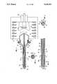
- FIG. 1is a diagram of an X-ray apparatus including a preferred embodiment of the interstitial X-ray needle of the present invention.
- FIG. 2is a sectional view of the needle of FIG. 1 taken along lines 2--2.
- FIG. 3is a diagram of a portion of the needle illustrating an alternative preferred embodiment of the flow-chamber defining means.
- FIG. 4is a sectional view of the needle of FIG. 3 taken along lines 4--4.
- an X-ray apparatus containing a preferred embodiment of the interstitial X-ray needle of the present inventionincludes the needle 10 and a diode housing 12 for receiving the needle.
- the diode housing 12includes a vacuum chamber 14 containing an electron emitter 16 and a control grid 18.
- the electron emitter 16is connected to a high voltage cable 20, which is connected to a high voltage source (not shown).
- Insulators 22are stacked between the electron emitter 16 and the diode housing 12.
- the needle 10includes an elongated X-ray tube 24, a converter element 26, a solenoid coil 28, and elongated outer casing 30 and a pipe 32.
- the X-ray tube 24has an open end 34 which opens into the vacuum chamber 14 to couple the X-ray tube 24 to the electron emitter 16.
- the converter element 26is disposed at a tip 36 of the other end of the tube 24 for converting electrons emitted from the electron emitter 16 into X-rays.
- the solenoid coil 28is wound around the tube 24 for providing a magnetic field that confines the emitted electrons within a narrow beam.
- the electron beamcan be confined to a diameter of approximately 0.4 millimeter when the solenoid coil 28 provides a magnetic field of approximately 20 gauss.
- the required current in the windingis only 0.8 amperes and the required voltage across the coil is only 0.1 volts, whereby the power expended in the winding is only 0.08 watts.
- the outer casing 30encloses the tube 24 and coil 28.
- the pipe 32is coaxially disposed between the outer casing 30 and the tube 24 for defining an inner annular flow channel 38 between the tip 36 of the tube 24 and a coolant inlet 40 in the casing 30, and an outer annular flow chamber 42 between the tip 36 of the tube 24 and a coolant outlet 44 in the casing 30.
- a water flow rate of 87 milliliters-per-minuteis obtained at an inlet pressure of 20 pounds-per-square-inch, whereby for a 20 watt heat rate at the tip 36 of the needle 10, the water temperature rise over ten minutes is less than 5 degrees Celsius.
- the needle 10Aincludes an elongated X-ray tube 24, a converter element 26, a solenoid coil 28, an elongated outer casing 30 and a plurality of pipes 46.
- the pipes 46are disposed between the casing 30 and the tube 24.
- Each pipedefines an input flow chamber 48 between the tip 36 of the tube 24 and at least one inlet opening (not shown) in the casing 30; and the space 50 between the tube 24 and the casing 30 not occupied by the pipes 46 defines an output flow chamber between the tip 36 of the tube 24 and an outlet opening (not shown) in the casing 30.
- a needle 10A of the embodiment of FIGS. 3 and 4including a ten-centimeter long tube 24 having an inside diameter of 0.64 millimeter and an outside diameter of 0.81 millimeter wound with a single layer of #33 magnetic wire of 0.22 millimeter diameter at approximately 40 turns-per-centimeter, an outer casing 30 having an outside diameter of 2.8 millimeters and an inside diameter of 2.16 millimeters, and four pipes each having outlet orifice jets 52 of 0.15 millimeter directed at the tip 36 of the needle 10A, a water flow rate of 10 milliliters-per-minute is obtained at an inlet pressure of 50 pounds-per-square-inch, whereby for a 20 watt heat rate at the tip 36 of the needle 10A, the water temperature rise over ten minutes is approximately 28 degrees Celsius.
- the tube 24, casing 30 and pipe 32 or pipes 46typically are rigid and straight, but also may be made of flexibe materials or may be curved rather than straight so as to enable insertion of the tip of the needle to portions of the body that are not directly accessible through soft tissue.
- the X-ray apparatus described hereinmay be operated at a relatively low power level of 14 watts when delivering a radiation dose of approximately 100 Gray over ten minutes duration to tissue located one centimeter from the converter element 26 by operating with an electron emitter voltage of 200 kilovolts and a beam current of 0.07 milliamperes.
- the miniature interstitial X-ray needle of the present inventionalso may generate controlled hyperthermic temperatures for application to the treated tumor, which combined with the radiation treatment may provide a synergistic healing effect.
Landscapes
- Health & Medical Sciences (AREA)
- Engineering & Computer Science (AREA)
- Biomedical Technology (AREA)
- Life Sciences & Earth Sciences (AREA)
- Nuclear Medicine, Radiotherapy & Molecular Imaging (AREA)
- Radiology & Medical Imaging (AREA)
- Pathology (AREA)
- Animal Behavior & Ethology (AREA)
- General Health & Medical Sciences (AREA)
- Public Health (AREA)
- Veterinary Medicine (AREA)
- Radiation-Therapy Devices (AREA)
- X-Ray Techniques (AREA)
Abstract
Description
Claims (6)
Priority Applications (7)
| Application Number | Priority Date | Filing Date | Title |
|---|---|---|---|
| US07/855,664US5165093A (en) | 1992-03-23 | 1992-03-23 | Interstitial X-ray needle |
| CA002090210ACA2090210C (en) | 1992-03-23 | 1993-02-23 | Interstitial x-ray needle |
| EP93302049AEP0562759B1 (en) | 1992-03-23 | 1993-03-18 | Interstitial X-ray needle |
| DE69311415TDE69311415T2 (en) | 1992-03-23 | 1993-03-18 | Interstitial x-ray needle |
| DK93302049.7TDK0562759T3 (en) | 1992-03-23 | 1993-03-18 | Interstitial X-ray |
| JP5062246AJPH06142220A (en) | 1992-03-23 | 1993-03-22 | X-ray needle of gap structure |
| US08/270,261USRE35383E (en) | 1992-03-23 | 1994-07-05 | Interstitial X-ray needle |
Applications Claiming Priority (1)
| Application Number | Priority Date | Filing Date | Title |
|---|---|---|---|
| US07/855,664US5165093A (en) | 1992-03-23 | 1992-03-23 | Interstitial X-ray needle |
Related Child Applications (1)
| Application Number | Title | Priority Date | Filing Date |
|---|---|---|---|
| US08/270,261ReissueUSRE35383E (en) | 1992-03-23 | 1994-07-05 | Interstitial X-ray needle |
Publications (1)
| Publication Number | Publication Date |
|---|---|
| US5165093Atrue US5165093A (en) | 1992-11-17 |
Family
ID=25321797
Family Applications (2)
| Application Number | Title | Priority Date | Filing Date |
|---|---|---|---|
| US07/855,664CeasedUS5165093A (en) | 1992-03-23 | 1992-03-23 | Interstitial X-ray needle |
| US08/270,261Expired - LifetimeUSRE35383E (en) | 1992-03-23 | 1994-07-05 | Interstitial X-ray needle |
Family Applications After (1)
| Application Number | Title | Priority Date | Filing Date |
|---|---|---|---|
| US08/270,261Expired - LifetimeUSRE35383E (en) | 1992-03-23 | 1994-07-05 | Interstitial X-ray needle |
Country Status (6)
| Country | Link |
|---|---|
| US (2) | US5165093A (en) |
| EP (1) | EP0562759B1 (en) |
| JP (1) | JPH06142220A (en) |
| CA (1) | CA2090210C (en) |
| DE (1) | DE69311415T2 (en) |
| DK (1) | DK0562759T3 (en) |
Cited By (38)
| Publication number | Priority date | Publication date | Assignee | Title |
|---|---|---|---|---|
| WO1994008350A1 (en)* | 1992-10-02 | 1994-04-14 | Photoelectron Corporation | Low-power x-ray source with implantable probe for treatment of brain tumors |
| US5305462A (en)* | 1986-09-18 | 1994-04-19 | Digital Equipment Corporation | Mechanism for broadcasting data in a massively parallell array processing system |
| WO1995004501A1 (en)* | 1993-08-09 | 1995-02-16 | Photoelectron Corporation | Method for treating brain tumors |
| US5422926A (en)* | 1990-09-05 | 1995-06-06 | Photoelectron Corporation | X-ray source with shaped radiation pattern |
| US5566221A (en)* | 1994-07-12 | 1996-10-15 | Photoelectron Corporation | Apparatus for applying a predetermined x-radiation flux to an interior surface of a body cavity |
| US5621780A (en)* | 1990-09-05 | 1997-04-15 | Photoelectron Corporation | X-ray apparatus for applying a predetermined flux to an interior surface of a body cavity |
| US5689542A (en)* | 1996-06-06 | 1997-11-18 | Varian Associates, Inc. | X-ray generating apparatus with a heat transfer device |
| US5729583A (en)* | 1995-09-29 | 1998-03-17 | The United States Of America As Represented By The Secretary Of Commerce | Miniature x-ray source |
| US5737384A (en)* | 1996-10-04 | 1998-04-07 | Massachusetts Institute Of Technology | X-ray needle providing heating with microwave energy |
| US5854822A (en)* | 1997-07-25 | 1998-12-29 | Xrt Corp. | Miniature x-ray device having cold cathode |
| US6069938A (en)* | 1998-03-06 | 2000-05-30 | Chornenky; Victor Ivan | Method and x-ray device using pulse high voltage source |
| US6095966A (en)* | 1997-02-21 | 2000-08-01 | Xrt Corp. | X-ray device having a dilation structure for delivering localized radiation to an interior of a body |
| US6108402A (en)* | 1998-01-16 | 2000-08-22 | Medtronic Ave, Inc. | Diamond vacuum housing for miniature x-ray device |
| US6134295A (en)* | 1998-10-29 | 2000-10-17 | University Of New Mexico | Apparatus using a x-ray source for radiation therapy port verification |
| US6195411B1 (en) | 1999-05-13 | 2001-02-27 | Photoelectron Corporation | Miniature x-ray source with flexible probe |
| US6285735B1 (en) | 2000-02-11 | 2001-09-04 | Photoelectron Corporation | Apparatus for local radiation therapy |
| US6289079B1 (en) | 1999-03-23 | 2001-09-11 | Medtronic Ave, Inc. | X-ray device and deposition process for manufacture |
| US6301328B1 (en) | 2000-02-11 | 2001-10-09 | Photoelectron Corporation | Apparatus for local radiation therapy |
| US6353658B1 (en) | 1999-09-08 | 2002-03-05 | The Regents Of The University Of California | Miniature x-ray source |
| US6377846B1 (en) | 1997-02-21 | 2002-04-23 | Medtronic Ave, Inc. | Device for delivering localized x-ray radiation and method of manufacture |
| EP1217642A1 (en)* | 2000-12-22 | 2002-06-26 | Radi Medical Technologies AB | Active cooling of a miniature x-ray tube |
| US6421416B1 (en) | 2000-02-11 | 2002-07-16 | Photoelectron Corporation | Apparatus for local radiation therapy |
| US6480573B1 (en)* | 2001-12-04 | 2002-11-12 | Photoelectron Corporation | Therapeutic radiation source with increased cathode efficiency |
| US6540655B1 (en) | 2000-11-10 | 2003-04-01 | Scimed Life Systems, Inc. | Miniature x-ray unit |
| US6551278B1 (en)* | 2000-11-10 | 2003-04-22 | Scimed Life Systems, Inc. | Miniature x-ray catheter with retractable needles or suction means for positioning at a desired site |
| US20030147501A1 (en)* | 2000-11-10 | 2003-08-07 | Geitz Kurt Alfred Edward | Heat sink for miniature x-ray unit |
| US20030179854A1 (en)* | 2002-03-20 | 2003-09-25 | Ali Jaafar | X-ray apparatus with field emission current stabilization and method of providing x-ray radiation therapy |
| US6706014B2 (en) | 2000-11-10 | 2004-03-16 | Scimed Life Systems, Inc. | Miniature x-ray unit |
| US6752752B2 (en) | 2000-11-10 | 2004-06-22 | Scimed Life Systems, Inc. | Multi-source x-ray catheter |
| US6799075B1 (en) | 1995-08-24 | 2004-09-28 | Medtronic Ave, Inc. | X-ray catheter |
| US7109505B1 (en) | 2000-02-11 | 2006-09-19 | Carl Zeiss Ag | Shaped biocompatible radiation shield and method for making same |
| US20080021257A1 (en)* | 2006-07-18 | 2008-01-24 | Ams Research Corporation | X-Ray Brachytherapy System and Device |
| US20100002841A1 (en)* | 2008-07-01 | 2010-01-07 | Ali Jaafar | Field emission x-ray apparatus, methods, and systems |
| WO2013171491A1 (en)* | 2012-05-16 | 2013-11-21 | Ariane Medical Systems Limited | Radiotherapy apparatus |
| US8915833B1 (en) | 2011-02-15 | 2014-12-23 | Velayudhan Sahadevan | Image guided intraoperative simultaneous several ports microbeam radiation therapy with microfocus X-ray tubes |
| US9636525B1 (en) | 2011-02-15 | 2017-05-02 | Velayudhan Sahadevan | Method of image guided intraoperative simultaneous several ports microbeam radiation therapy with microfocus X-ray tubes |
| EP1404517B1 (en)* | 2001-06-18 | 2017-11-15 | Alfred E. Mann Foundation for Scientific Research | Application and manufacturing method for a zirconia ceramic to titanium alloy metal seal |
| DE102018114000A1 (en)* | 2018-06-12 | 2019-12-12 | Carl Zeiss Meditec Ag | Medical radiotherapy system and method of operating the same |
Families Citing this family (38)
| Publication number | Priority date | Publication date | Assignee | Title |
|---|---|---|---|---|
| FR2728472B1 (en)* | 1994-12-27 | 1997-03-28 | Ge Medical Syst Sa | RADIATION THERAPY APPARATUS USING A HIGH FREQUENCY LINEAR ELECTRON ACCELERATOR AND NON-FIELD PROTECTIVE MEANS |
| EP0797765B1 (en)* | 1995-10-09 | 2007-02-21 | Otsuka Pharmaceutical Co., Ltd. | Method of spectrometrically measuring the concentration ratio of two isotopes in a gas |
| AU726908B2 (en)* | 1995-10-09 | 2000-11-23 | Otsuka Pharmaceutical Co., Ltd. | Breath sampling bag and gas measuring apparatus |
| US6249569B1 (en)* | 1998-12-22 | 2001-06-19 | General Electric Company | X-ray tube having increased cooling capabilities |
| AU2738001A (en)* | 1999-12-28 | 2001-07-09 | Apple, Marc G. | Enhanced energy radiotherapy balloon catheter |
| EP1409058A2 (en) | 2000-01-28 | 2004-04-21 | William Cook Europe ApS | Endovascular medical device with plurality of wires |
| US6661876B2 (en) | 2001-07-30 | 2003-12-09 | Moxtek, Inc. | Mobile miniature X-ray source |
| CA2454644C (en)* | 2002-08-14 | 2014-09-16 | Gw Pharma Limited | Cannabinoid liquid formulations for mucosal administration |
| EP1547116A4 (en)* | 2002-09-13 | 2006-05-24 | Moxtek Inc | Radiation window and method of manufacture |
| US7158612B2 (en)* | 2003-02-21 | 2007-01-02 | Xoft, Inc. | Anode assembly for an x-ray tube |
| EP1493466B1 (en)* | 2003-06-30 | 2012-06-20 | Nucletron Operations B.V. | Miniature X-ray source with cryogenic cooling |
| US7428298B2 (en)* | 2005-03-31 | 2008-09-23 | Moxtek, Inc. | Magnetic head for X-ray source |
| US7382862B2 (en)* | 2005-09-30 | 2008-06-03 | Moxtek, Inc. | X-ray tube cathode with reduced unintended electrical field emission |
| US7737424B2 (en)* | 2007-06-01 | 2010-06-15 | Moxtek, Inc. | X-ray window with grid structure |
| US7529345B2 (en)* | 2007-07-18 | 2009-05-05 | Moxtek, Inc. | Cathode header optic for x-ray tube |
| US9305735B2 (en) | 2007-09-28 | 2016-04-05 | Brigham Young University | Reinforced polymer x-ray window |
| US8498381B2 (en) | 2010-10-07 | 2013-07-30 | Moxtek, Inc. | Polymer layer on X-ray window |
| US8736138B2 (en) | 2007-09-28 | 2014-05-27 | Brigham Young University | Carbon nanotube MEMS assembly |
| EP2195860A4 (en)* | 2007-09-28 | 2010-11-24 | Univ Brigham Young | X-RAY WINDOW WITH CARBON NANOTUBE FRAME |
| US8247971B1 (en) | 2009-03-19 | 2012-08-21 | Moxtek, Inc. | Resistively heated small planar filament |
| US7983394B2 (en) | 2009-12-17 | 2011-07-19 | Moxtek, Inc. | Multiple wavelength X-ray source |
| DE102010032338B4 (en)* | 2010-07-27 | 2017-08-24 | X-Ray Worx Gmbh | Microfocus X-ray tube |
| US8995621B2 (en) | 2010-09-24 | 2015-03-31 | Moxtek, Inc. | Compact X-ray source |
| US8526574B2 (en) | 2010-09-24 | 2013-09-03 | Moxtek, Inc. | Capacitor AC power coupling across high DC voltage differential |
| US8804910B1 (en) | 2011-01-24 | 2014-08-12 | Moxtek, Inc. | Reduced power consumption X-ray source |
| US8750458B1 (en) | 2011-02-17 | 2014-06-10 | Moxtek, Inc. | Cold electron number amplifier |
| US8929515B2 (en) | 2011-02-23 | 2015-01-06 | Moxtek, Inc. | Multiple-size support for X-ray window |
| US8792619B2 (en) | 2011-03-30 | 2014-07-29 | Moxtek, Inc. | X-ray tube with semiconductor coating |
| US8989354B2 (en) | 2011-05-16 | 2015-03-24 | Brigham Young University | Carbon composite support structure |
| US9174412B2 (en) | 2011-05-16 | 2015-11-03 | Brigham Young University | High strength carbon fiber composite wafers for microfabrication |
| US9076628B2 (en) | 2011-05-16 | 2015-07-07 | Brigham Young University | Variable radius taper x-ray window support structure |
| JP5804777B2 (en)* | 2011-06-01 | 2015-11-04 | キヤノン株式会社 | X-ray generator tube and X-ray generator |
| US8817950B2 (en) | 2011-12-22 | 2014-08-26 | Moxtek, Inc. | X-ray tube to power supply connector |
| US8761344B2 (en) | 2011-12-29 | 2014-06-24 | Moxtek, Inc. | Small x-ray tube with electron beam control optics |
| US9072154B2 (en) | 2012-12-21 | 2015-06-30 | Moxtek, Inc. | Grid voltage generation for x-ray tube |
| US9184020B2 (en) | 2013-03-04 | 2015-11-10 | Moxtek, Inc. | Tiltable or deflectable anode x-ray tube |
| US9177755B2 (en) | 2013-03-04 | 2015-11-03 | Moxtek, Inc. | Multi-target X-ray tube with stationary electron beam position |
| US9173623B2 (en) | 2013-04-19 | 2015-11-03 | Samuel Soonho Lee | X-ray tube and receiver inside mouth |
Citations (13)
| Publication number | Priority date | Publication date | Assignee | Title |
|---|---|---|---|---|
| US2651727A (en)* | 1950-03-22 | 1953-09-08 | Ehrenberg Werner | X-ray tube |
| US2748293A (en)* | 1951-09-08 | 1956-05-29 | Hartford Nat Bank & Trust Co | Irradiation applicator for X-ray therapy |
| US3609432A (en)* | 1968-11-08 | 1971-09-28 | Rigaku Denki Co Ltd | Thin target x-ray tube with means for protecting the target |
| US3668454A (en)* | 1969-08-05 | 1972-06-06 | Rigaku Denki Co Ltd | Fine focus x-ray tube |
| US3783251A (en)* | 1970-11-27 | 1974-01-01 | Varian Associates | Computer assisted radiation therapy machine |
| US3969629A (en)* | 1975-03-14 | 1976-07-13 | Varian Associates | X-ray treatment machine having means for reducing secondary electron skin dose |
| US4157475A (en)* | 1977-10-21 | 1979-06-05 | Applied Radiation Corporation | Electron accelerator comprising a target exposed to the electron beam |
| US4409993A (en)* | 1980-07-23 | 1983-10-18 | Olympus Optical Co., Ltd. | Endoscope apparatus |
| US4763671A (en)* | 1983-12-27 | 1988-08-16 | Stanford University | Method of treating tumors using selective application of heat and radiation |
| US4825880A (en)* | 1987-06-19 | 1989-05-02 | The Regents Of The University Of California | Implantable helical coil microwave antenna |
| US4969863A (en)* | 1988-10-28 | 1990-11-13 | Eric van't Hooft | Adaptor for remote after-loading apparatus for radiotherapy |
| US4993430A (en)* | 1987-01-06 | 1991-02-19 | Omron Tateisi Electronics Co. | Electrode device for high frequency thermotherapy apparatus |
| US5026959A (en)* | 1988-11-16 | 1991-06-25 | Tokyo Keiki Co. Ltd. | Microwave radiator for warming therapy |
Family Cites Families (3)
| Publication number | Priority date | Publication date | Assignee | Title |
|---|---|---|---|---|
| DE710118C (en)* | 1938-02-26 | 1941-09-04 | Dr Marius Kratzenstein | Hollow anode tube with magnetic shield |
| US2356645A (en)* | 1943-02-08 | 1944-08-22 | Gen Electric X Ray Corp | X-ray tube |
| US2362816A (en)* | 1943-04-15 | 1944-11-14 | Gen Electric | Electrical discharge device |
- 1992
- 1992-03-23USUS07/855,664patent/US5165093A/ennot_activeCeased
- 1993
- 1993-02-23CACA002090210Apatent/CA2090210C/ennot_activeExpired - Fee Related
- 1993-03-18DKDK93302049.7Tpatent/DK0562759T3/enactive
- 1993-03-18EPEP93302049Apatent/EP0562759B1/ennot_activeExpired - Lifetime
- 1993-03-18DEDE69311415Tpatent/DE69311415T2/ennot_activeExpired - Fee Related
- 1993-03-22JPJP5062246Apatent/JPH06142220A/enactivePending
- 1994
- 1994-07-05USUS08/270,261patent/USRE35383E/ennot_activeExpired - Lifetime
Patent Citations (13)
| Publication number | Priority date | Publication date | Assignee | Title |
|---|---|---|---|---|
| US2651727A (en)* | 1950-03-22 | 1953-09-08 | Ehrenberg Werner | X-ray tube |
| US2748293A (en)* | 1951-09-08 | 1956-05-29 | Hartford Nat Bank & Trust Co | Irradiation applicator for X-ray therapy |
| US3609432A (en)* | 1968-11-08 | 1971-09-28 | Rigaku Denki Co Ltd | Thin target x-ray tube with means for protecting the target |
| US3668454A (en)* | 1969-08-05 | 1972-06-06 | Rigaku Denki Co Ltd | Fine focus x-ray tube |
| US3783251A (en)* | 1970-11-27 | 1974-01-01 | Varian Associates | Computer assisted radiation therapy machine |
| US3969629A (en)* | 1975-03-14 | 1976-07-13 | Varian Associates | X-ray treatment machine having means for reducing secondary electron skin dose |
| US4157475A (en)* | 1977-10-21 | 1979-06-05 | Applied Radiation Corporation | Electron accelerator comprising a target exposed to the electron beam |
| US4409993A (en)* | 1980-07-23 | 1983-10-18 | Olympus Optical Co., Ltd. | Endoscope apparatus |
| US4763671A (en)* | 1983-12-27 | 1988-08-16 | Stanford University | Method of treating tumors using selective application of heat and radiation |
| US4993430A (en)* | 1987-01-06 | 1991-02-19 | Omron Tateisi Electronics Co. | Electrode device for high frequency thermotherapy apparatus |
| US4825880A (en)* | 1987-06-19 | 1989-05-02 | The Regents Of The University Of California | Implantable helical coil microwave antenna |
| US4969863A (en)* | 1988-10-28 | 1990-11-13 | Eric van't Hooft | Adaptor for remote after-loading apparatus for radiotherapy |
| US5026959A (en)* | 1988-11-16 | 1991-06-25 | Tokyo Keiki Co. Ltd. | Microwave radiator for warming therapy |
Cited By (55)
| Publication number | Priority date | Publication date | Assignee | Title |
|---|---|---|---|---|
| US5305462A (en)* | 1986-09-18 | 1994-04-19 | Digital Equipment Corporation | Mechanism for broadcasting data in a massively parallell array processing system |
| US5369679A (en)* | 1990-09-05 | 1994-11-29 | Photoelectron Corporation | Low power x-ray source with implantable probe for treatment of brain tumors |
| US5422926A (en)* | 1990-09-05 | 1995-06-06 | Photoelectron Corporation | X-ray source with shaped radiation pattern |
| US5442678A (en)* | 1990-09-05 | 1995-08-15 | Photoelectron Corporation | X-ray source with improved beam steering |
| US5452720A (en)* | 1990-09-05 | 1995-09-26 | Photoelectron Corporation | Method for treating brain tumors |
| US5528652A (en)* | 1990-09-05 | 1996-06-18 | Photoelectron Corporation | Method for treating brain tumors |
| US5621780A (en)* | 1990-09-05 | 1997-04-15 | Photoelectron Corporation | X-ray apparatus for applying a predetermined flux to an interior surface of a body cavity |
| WO1994008350A1 (en)* | 1992-10-02 | 1994-04-14 | Photoelectron Corporation | Low-power x-ray source with implantable probe for treatment of brain tumors |
| WO1995004501A1 (en)* | 1993-08-09 | 1995-02-16 | Photoelectron Corporation | Method for treating brain tumors |
| US5428658A (en)* | 1994-01-21 | 1995-06-27 | Photoelectron Corporation | X-ray source with flexible probe |
| US5566221A (en)* | 1994-07-12 | 1996-10-15 | Photoelectron Corporation | Apparatus for applying a predetermined x-radiation flux to an interior surface of a body cavity |
| US6799075B1 (en) | 1995-08-24 | 2004-09-28 | Medtronic Ave, Inc. | X-ray catheter |
| US5729583A (en)* | 1995-09-29 | 1998-03-17 | The United States Of America As Represented By The Secretary Of Commerce | Miniature x-ray source |
| US5689542A (en)* | 1996-06-06 | 1997-11-18 | Varian Associates, Inc. | X-ray generating apparatus with a heat transfer device |
| US5737384A (en)* | 1996-10-04 | 1998-04-07 | Massachusetts Institute Of Technology | X-ray needle providing heating with microwave energy |
| WO1999032048A1 (en)* | 1996-10-04 | 1999-07-01 | Massachusetts Institute Of Technology | X-ray needle providing heating with microwave energy |
| US6095966A (en)* | 1997-02-21 | 2000-08-01 | Xrt Corp. | X-ray device having a dilation structure for delivering localized radiation to an interior of a body |
| US6377846B1 (en) | 1997-02-21 | 2002-04-23 | Medtronic Ave, Inc. | Device for delivering localized x-ray radiation and method of manufacture |
| US5854822A (en)* | 1997-07-25 | 1998-12-29 | Xrt Corp. | Miniature x-ray device having cold cathode |
| US6108402A (en)* | 1998-01-16 | 2000-08-22 | Medtronic Ave, Inc. | Diamond vacuum housing for miniature x-ray device |
| US6069938A (en)* | 1998-03-06 | 2000-05-30 | Chornenky; Victor Ivan | Method and x-ray device using pulse high voltage source |
| US6134295A (en)* | 1998-10-29 | 2000-10-17 | University Of New Mexico | Apparatus using a x-ray source for radiation therapy port verification |
| US6289079B1 (en) | 1999-03-23 | 2001-09-11 | Medtronic Ave, Inc. | X-ray device and deposition process for manufacture |
| US6195411B1 (en) | 1999-05-13 | 2001-02-27 | Photoelectron Corporation | Miniature x-ray source with flexible probe |
| US6320932B2 (en) | 1999-05-13 | 2001-11-20 | Photoelectron Corporation | Miniature radiation source with flexible probe and laser driven thermionic emitter |
| US6353658B1 (en) | 1999-09-08 | 2002-03-05 | The Regents Of The University Of California | Miniature x-ray source |
| US6285735B1 (en) | 2000-02-11 | 2001-09-04 | Photoelectron Corporation | Apparatus for local radiation therapy |
| US7109505B1 (en) | 2000-02-11 | 2006-09-19 | Carl Zeiss Ag | Shaped biocompatible radiation shield and method for making same |
| US6421416B1 (en) | 2000-02-11 | 2002-07-16 | Photoelectron Corporation | Apparatus for local radiation therapy |
| US6301328B1 (en) | 2000-02-11 | 2001-10-09 | Photoelectron Corporation | Apparatus for local radiation therapy |
| US7031432B2 (en) | 2000-11-10 | 2006-04-18 | Scimed Life Systems, Inc. | Miniature x-ray catheter with retractable needles or suction means for positioning at a desired site |
| US6551278B1 (en)* | 2000-11-10 | 2003-04-22 | Scimed Life Systems, Inc. | Miniature x-ray catheter with retractable needles or suction means for positioning at a desired site |
| US20030147501A1 (en)* | 2000-11-10 | 2003-08-07 | Geitz Kurt Alfred Edward | Heat sink for miniature x-ray unit |
| US20030149331A1 (en)* | 2000-11-10 | 2003-08-07 | Geitz Kurt Alfred Edward | Miniature X-ray catheter with retractable needles or suction means for positioning at a desired site |
| US20100266101A1 (en)* | 2000-11-10 | 2010-10-21 | Boston Scientific Scimed, Inc. | Miniature x-ray unit |
| US6706014B2 (en) | 2000-11-10 | 2004-03-16 | Scimed Life Systems, Inc. | Miniature x-ray unit |
| US6752752B2 (en) | 2000-11-10 | 2004-06-22 | Scimed Life Systems, Inc. | Multi-source x-ray catheter |
| US6540655B1 (en) | 2000-11-10 | 2003-04-01 | Scimed Life Systems, Inc. | Miniature x-ray unit |
| US6999559B2 (en) | 2000-11-10 | 2006-02-14 | Scimed Life Systems, Inc. | Heat sink for miniature x-ray unit |
| US7901345B2 (en) | 2000-11-10 | 2011-03-08 | Boston Scientific Scimed, Inc | Miniature X-ray unit |
| EP1217642A1 (en)* | 2000-12-22 | 2002-06-26 | Radi Medical Technologies AB | Active cooling of a miniature x-ray tube |
| EP1404517B1 (en)* | 2001-06-18 | 2017-11-15 | Alfred E. Mann Foundation for Scientific Research | Application and manufacturing method for a zirconia ceramic to titanium alloy metal seal |
| US6480573B1 (en)* | 2001-12-04 | 2002-11-12 | Photoelectron Corporation | Therapeutic radiation source with increased cathode efficiency |
| US6985557B2 (en) | 2002-03-20 | 2006-01-10 | Minnesota Medical Physics Llc | X-ray apparatus with field emission current stabilization and method of providing x-ray radiation therapy |
| US20030179854A1 (en)* | 2002-03-20 | 2003-09-25 | Ali Jaafar | X-ray apparatus with field emission current stabilization and method of providing x-ray radiation therapy |
| US20080021257A1 (en)* | 2006-07-18 | 2008-01-24 | Ams Research Corporation | X-Ray Brachytherapy System and Device |
| US20100002841A1 (en)* | 2008-07-01 | 2010-01-07 | Ali Jaafar | Field emission x-ray apparatus, methods, and systems |
| US7965818B2 (en) | 2008-07-01 | 2011-06-21 | Minnesota Medical Physics Llc | Field emission X-ray apparatus, methods, and systems |
| US8005191B2 (en) | 2008-07-01 | 2011-08-23 | Minnesota Medical Physics Llc | Field emission X-ray apparatus, methods, and systems |
| US20100002840A1 (en)* | 2008-07-01 | 2010-01-07 | Ali Jaafar | Field emission x-ray apparatus, methods, and systems |
| US8915833B1 (en) | 2011-02-15 | 2014-12-23 | Velayudhan Sahadevan | Image guided intraoperative simultaneous several ports microbeam radiation therapy with microfocus X-ray tubes |
| US9636525B1 (en) | 2011-02-15 | 2017-05-02 | Velayudhan Sahadevan | Method of image guided intraoperative simultaneous several ports microbeam radiation therapy with microfocus X-ray tubes |
| WO2013171491A1 (en)* | 2012-05-16 | 2013-11-21 | Ariane Medical Systems Limited | Radiotherapy apparatus |
| DE102018114000A1 (en)* | 2018-06-12 | 2019-12-12 | Carl Zeiss Meditec Ag | Medical radiotherapy system and method of operating the same |
| DE102018114000B4 (en) | 2018-06-12 | 2020-06-10 | Carl Zeiss Meditec Ag | Medical radiation therapy system and method for operating the same |
Also Published As
| Publication number | Publication date |
|---|---|
| DK0562759T3 (en) | 1997-07-07 |
| JPH06142220A (en) | 1994-05-24 |
| DE69311415T2 (en) | 1997-10-16 |
| EP0562759B1 (en) | 1997-06-11 |
| CA2090210A1 (en) | 1993-09-24 |
| CA2090210C (en) | 2002-07-16 |
| EP0562759A1 (en) | 1993-09-29 |
| USRE35383E (en) | 1996-11-26 |
| DE69311415D1 (en) | 1997-07-17 |
Similar Documents
| Publication | Publication Date | Title |
|---|---|---|
| US5165093A (en) | Interstitial X-ray needle | |
| US6464625B2 (en) | Therapeutic method and apparatus for debilitating or killing microorganisms within the body | |
| US6320932B2 (en) | Miniature radiation source with flexible probe and laser driven thermionic emitter | |
| KR100251423B1 (en) | X-ray apparatus for applying a predetermined flux to an interior surface of a body cavity | |
| EP0860181B1 (en) | X-ray device having a dilatation structure for delivering localized radiation to an interior of a body | |
| US5153900A (en) | Miniaturized low power x-ray source | |
| US6556651B1 (en) | Array of miniature radiation sources | |
| US20020072645A1 (en) | Hyperthermia radiation apparatus and method for treatment of malignant tumors | |
| US20020115901A1 (en) | Medical system comprising a miniaturized X-ray tube | |
| WO2006065299A1 (en) | Catheter with inflatable balloon assembly and optically activated x-ray source | |
| US6134295A (en) | Apparatus using a x-ray source for radiation therapy port verification | |
| US20050038488A1 (en) | X-ray apparatus with field emission current stabilization and method of providing x-ray radiation therapy | |
| EP1217642A1 (en) | Active cooling of a miniature x-ray tube | |
| RU2238774C2 (en) | Device for applying radiation therapy |
Legal Events
| Date | Code | Title | Description |
|---|---|---|---|
| AS | Assignment | Owner name:TITAN CORPORATION, THE, A CORP. OF DE, CALIFORNIA Free format text:ASSIGNMENT OF ASSIGNORS INTEREST.;ASSIGNORS:MILLER, ROBERT B.;SMITH, JOHN R.;MUEHLENWEG, CARL A.;REEL/FRAME:006068/0563;SIGNING DATES FROM 19920317 TO 19920318 | |
| STCF | Information on status: patent grant | Free format text:PATENTED CASE | |
| RF | Reissue application filed | Effective date:19940705 | |
| FPAY | Fee payment | Year of fee payment:4 | |
| AS | Assignment | Owner name:SUMITOMO BANK OF CALIFORNIA, CALIFORNIA Free format text:SECURITY AGREEMENT;ASSIGNOR:TITAN CORPORATION, THE, A DELAWARE CORPORATION;REEL/FRAME:008126/0447 Effective date:19960906 | |
| AS | Assignment | Owner name:SUMITOMO BANK OF CALIFORNIA AS AGENT FOR ITSELF AN Free format text:SECURITY AGREEMENT;ASSIGNOR:SUMITOMO BANK OF CALIFORNIA, THE;REEL/FRAME:008535/0923 Effective date:19970515 | |
| AS | Assignment | Owner name:TITAN CORPORATION, THE, CALIFORNIA Free format text:TERMINATION OF INTEREST;ASSIGNOR:BANK OF NOVA SCOTIA, THE;REEL/FRAME:010832/0759 Effective date:20000223 | |
| AS | Assignment | Owner name:CREDIT SUISSE FIRST BOSTON, NEW YORK Free format text:SECURITY AGREEMENT;ASSIGNOR:THE TITAN CORPORATION;REEL/FRAME:010859/0353 Effective date:20000223 | |
| AS | Assignment | Owner name:WACHOVIA BANK, N.A., AS ADMINISTRATIVE AGENT, NORT Free format text:PATENT SECURITY AGREEMENT;ASSIGNOR:TITAN CORPORATION, THE;REEL/FRAME:013467/0626 Effective date:20020523 |