US5164903A - Electronic control of tractive force proportioning for a class of four wheel drive vehicles - Google Patents
Electronic control of tractive force proportioning for a class of four wheel drive vehiclesDownload PDFInfo
- Publication number
- US5164903A US5164903AUS07/578,372US57837290AUS5164903AUS 5164903 AUS5164903 AUS 5164903AUS 57837290 AUS57837290 AUS 57837290AUS 5164903 AUS5164903 AUS 5164903A
- Authority
- US
- United States
- Prior art keywords
- torque
- wheel speed
- rear wheel
- wheel
- sub
- Prior art date
- Legal status (The legal status is an assumption and is not a legal conclusion. Google has not performed a legal analysis and makes no representation as to the accuracy of the status listed.)
- Expired - Lifetime
Links
- 230000001133accelerationEffects0.000claimsabstractdescription50
- 230000004044responseEffects0.000claimsabstractdescription25
- 238000000034methodMethods0.000claimsabstractdescription20
- 238000012937correctionMethods0.000description6
- 238000010586diagramMethods0.000description5
- 238000009987spinningMethods0.000description5
- 230000005540biological transmissionEffects0.000description4
- 238000002485combustion reactionMethods0.000description4
- 238000012986modificationMethods0.000description2
- 230000004048modificationEffects0.000description2
- 238000012545processingMethods0.000description2
- 238000012360testing methodMethods0.000description2
- 238000012546transferMethods0.000description2
- 230000005355Hall effectEffects0.000description1
- 230000000994depressogenic effectEffects0.000description1
- 230000009977dual effectEffects0.000description1
- 238000005516engineering processMethods0.000description1
- 230000006870functionEffects0.000description1
- 230000003287optical effectEffects0.000description1
- 230000008569processEffects0.000description1
- 229910052761rare earth metalInorganic materials0.000description1
- 150000002910rare earth metalsChemical class0.000description1
- 230000003252repetitive effectEffects0.000description1
Images


Classifications
- B—PERFORMING OPERATIONS; TRANSPORTING
- B60—VEHICLES IN GENERAL
- B60K—ARRANGEMENT OR MOUNTING OF PROPULSION UNITS OR OF TRANSMISSIONS IN VEHICLES; ARRANGEMENT OR MOUNTING OF PLURAL DIVERSE PRIME-MOVERS IN VEHICLES; AUXILIARY DRIVES FOR VEHICLES; INSTRUMENTATION OR DASHBOARDS FOR VEHICLES; ARRANGEMENTS IN CONNECTION WITH COOLING, AIR INTAKE, GAS EXHAUST OR FUEL SUPPLY OF PROPULSION UNITS IN VEHICLES
- B60K28/00—Safety devices for propulsion-unit control, specially adapted for, or arranged in, vehicles, e.g. preventing fuel supply or ignition in the event of potentially dangerous conditions
- B60K28/10—Safety devices for propulsion-unit control, specially adapted for, or arranged in, vehicles, e.g. preventing fuel supply or ignition in the event of potentially dangerous conditions responsive to conditions relating to the vehicle
- B60K28/16—Safety devices for propulsion-unit control, specially adapted for, or arranged in, vehicles, e.g. preventing fuel supply or ignition in the event of potentially dangerous conditions responsive to conditions relating to the vehicle responsive to, or preventing, spinning or skidding of wheels
- B60K28/165—Safety devices for propulsion-unit control, specially adapted for, or arranged in, vehicles, e.g. preventing fuel supply or ignition in the event of potentially dangerous conditions responsive to conditions relating to the vehicle responsive to, or preventing, spinning or skidding of wheels acting on elements of the vehicle drive train other than the propulsion unit and brakes, e.g. transmission, clutch, differential
Definitions
- This inventionrelates to traction control for a class of four wheel drive vehicles and more particularly to a means and method of electronically proportioning tractive force among the vehicle wheels in response to front and rear wheel speed and acceleration.
- the state of the art technology for achieving ideal wheel torque proportioningis to use a locked differential between the front and rear axles which results in identical front and rear wheel speeds. Providing identical front and rear wheel speeds is a very effective way of ensuring ideal proportioning of wheel torque and, consequently, tractive force.
- the present inventionis a powertrain control system for four wheel drive vehicles that provides ideal tractive torque proportioning by controlling both front and rear wheels to rotate at the same speed.
- the controllerreceives signal processing information, including accelerator pedal position and front and rear wheel speeds and accelerations, determines the torque requirements for the front and rear wheels based upon the input signals, and controls the powertrain to deliver the required torque to the wheels.
- the inventioncan be implemented in a vehicle which has a front engine and a rear engine/motor delivering power to the front and rear wheels through front and rear differentials.
- the controllercontrols the drive torque to the front and rear wheels by controlling the output of the front and rear engines/motors, e.g., through control of engine throttles.
- the inventioncan be implemented in a vehicle which has a separate drive train for each of the four vehicle wheels, such as an electric vehicle with a direct drive DC motor for each wheel.
- the controllercontrols the drive torque to the left front and left rear wheels, e.g., through control of the current to the DC drive motors. The same process is repeated for the right front and right rear wheels.
- the torque control for the front and rear wheelsincludes an open-loop and a closed-loop portion.
- the wheel (front or rear) that is turning sloweris controlled in response to the open-loop command from the accelerator pedal position.
- the wheel that is turning fasteris controlled in response to the open-loop command from the accelerator pedal position and the closed-loop command derived from the front and rear wheel speeds and accelerations, to reduce the drive torque to that wheel.
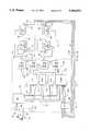
- FIG. 1ais a schematic drawing of a four wheel drive vehicle with a controller controlling front and rear powertrains which drive front and rear wheels through front and rear differentials.
- FIG. 1bis a schematic drawing of a four wheel drive vehicle with a controller controlling separate power trains for each wheel.
- FIG. 2is a schematic diagram showing components of the controller and its connections for implementation of the invention in the vehicle depicted in FIG. 1a.
- FIG. 3is a schematic diagram showing components of the controller and its connections for implementation of the invention in the vehicle depicted in FIG. 1b.
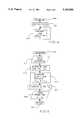
- FIG. 4is a basic flow diagram of a torque control routine.
- FIG. 5is a flow diagram of the interrupt loop of a torque control routine.
- FIG. 6is a detailed flow diagram of a routine for determining the front and rear torque commands.
- the accelerator pedal positionis input and used as the open loop torque command, T p .
- the front and rear wheel speeds, ⁇ f and ⁇ r , and front and rear wheel accelerations, ⁇ f and ⁇ rare measured to determine the closed loop torque command, T fb , according to the following equation:
- K p and K.sub. ⁇are proportionality constants which may be tailored to meet the desired performance of a particular vehicle.
- the larger the proportionality constants, K p and K.sub. ⁇the faster the response of the system.
- large proportionality constantstend to provide rides which may be characterized by brief repetitive periods of sudden accelerations and decelerations. By reducing the proportionality constants, a smoother ride can be obtained at a sacrifice to response speed.
- a comparisonis made between the front wheels and the rear wheel speeds to determine the difference in speed, if any.
- the preferred methodis done by finding a wheel speed ratio ⁇ f / ⁇ r and comparing that ratio to a predetermined constant, R th , e.g., R th +1.05, to determine if any torque correction is desired. If the wheel speed ratio is less than R th and the inverse of the wheel speed ratio, ⁇ r / ⁇ f , is less than R th , then no torque correction is required. In the case where no torque correction is required, the open loop torque command, T p , is applied to both the front and rear wheels.
- the open loop torque command, T pis applied to the rear wheels.
- the sum of the open loop torque command and the closed loop torque command, T p +T fbis applied to the front wheels, reducing the torque drive to the front wheels and reducing the front wheel spin.
- each wheelprovides a drive torque and tractive force for the vehicle proportional to both the vehicle loading on the wheel and the friction coefficient between the wheel and the road surface.
- the vehicle 10ahas a front engine and transmission 12 driving front wheels 14 and 20 through differential 16.
- a rear engine and transmission 40drives the rear wheels 32 and 38 through differential 34.
- the enginesare internal combustion engines with throttles (see FIG. 2) controlled by controller 22a through lines 24 and 28.
- the average front wheel speed and accelerationare sensed by sensor 18 at the input shaft to the front differential 16 and fed back to the controller 22a through line 26.
- the average rear wheel speed and accelerationare sensed by sensor 36 at the input shaft to the rear differential 34 and fed back to the controller 22a through line 30.
- the sensors 18 and 36are preferably hall effect sensors detecting the rotation of the differential input shafts but may also be magneto-resistive sensors, variable reluctance sensors, or any other suitable sensor.
- the controller 22aincludes the clock 26, microcomputer 108, front and rear throttle drivers 112 and 118, input/output unit 124, ROM and RAM memory units 128 and 130, timer 132 and counter 136.
- the microcomputer 108executes the control program stored in read only memory 128 at a frequency determined by clock 106.
- the microcomputercontrols the input/output unit 124, ROM 128, RAM 130 and timer 132 through control bus 120 and transfers data between the units through bi-directional data bus 122.
- the accelerator pedal 100has a position sensed by sensor 102, which may be a potentiometer, optical encoder, or any other suitable position sensor.
- a signal representative of the accelerator pedal positionis input to the input/output unit 124 through line 104 and a number representative of the gas pedal position is stored in the RAM 130.
- the counter 136receives pulses indicative of differential input shaft rotations through lines 26 and 30.
- the countersupplies the counts to the timer 132 through lines 134a.
- the microcomputer 108can determine the average front and rear wheel speeds, ⁇ f and ⁇ r , and the average front and rear wheel accelerations, ⁇ f and ⁇ r , and store the speed and acceleration information in RAM 130.
- the microcomputer 108determines the desired torque output for the front and rear wheels in accordance with the method set forth above.
- the input/output unit 124outputs the torque commands to the front and rear throttle drivers 112 and 118 through control buses 114 and 116.
- the front throttle driversends a control signal through line 24 to drive actuator 138, preferably a stepper motor, which controls the position of the front engine throttle 146 through actuator shaft 142.
- the throttle positionis sensed by sensor 148 and fed back to the controller 22a through line 110.
- the front throttle 146controls the power output of the front engine 150 which delivers power, at the desired torque, to the front wheels (not shown) through the front transmission 152 and front differential 16.
- the rear throttle driversends a control signal through line 28 to the rear actuator 140, also preferably a stepper motor, which controls the position of the rear throttle 154 through movement of the actuator shaft 144.
- the rear throttle positionis sensed by sensor 156 and fed back to the controller 22a through line 126.
- the rear throttle 154controls the power output of the rear engine 158 which delivers power, at the desired torque, to the rear wheels (not shown) through the rear transmission 160 and rear differential 34.
- control program implemented by the microcomputeris powered up and initialized, 200 and 202, when the vehicle operator turns the ignition key.
- various variablessuch as the counter contents and front and rear control status are reset. Additionally, the necessary start-up sequences for operation of the microcomputer, which are well known to those skilled in the art, are performed.
- the microcomputerenters the control loop 204 to execute the algorithms based on a predetermined interrupt interval, preferably 10 ms.
- the microcomputerenters the interrupt routine at step 210 and at step 212, receives input signals and performs input signal processing.
- the input signalsinclude information from the counter, timer, and accelerator pedal (136, 132, and 100 in FIG. 2).
- the open loop torque command, T pis determined in response to the accelerator pedal position.
- the open loop torque commandis usually directly proportional to accelerator pedal position but different transfer functions between the accelerator pedal position and open loop torque command may be designed to achieve particular vehicle performances. For example, large torque output may be desired when the accelerator pedal is initially depressed so that the vehicle "jumps" at initial acceleration, and this can easily be programmed into the open loop torque command control by one skilled in the art.
- the closed loop torque commands, for the front and rear wheels, T fbf and T fbrare determined.
- the front and rear torque commands, T F and T Rwhich are determined at step 217, are output to control the front and rear engines 12 and 40 to reducing wheel spin and achieving proper tractive force proportioning among the wheels.
- the programreturns out of the interrupt loop.
- the preferred implementation for determining the front and rear torque commands, T F and T Rstarts at step 230.
- the microcomputertests to determine if either the average front or average rear wheel speed ( ⁇ f or ⁇ r ) is zero. If either the front or rear average wheel speeds is zero, then the closed loop torque commands for both the front and the rear wheels, T fbf and T fbr , are set to zero at step 248 and the front and rear torque commands, T F and T R , are set to the open loop torque command, T p , at step 250.
- the controllerdetermines the closed loop torque command, T fb +K p ⁇ +K 60 ⁇ .
- the controllertests the front to rear average wheel speed ratio, R f , against a predetermined constant, R th , preferably 1.05, to determine if torque correction should be applied to the front wheels. If the front to rear average wheel speed ratio is greater than R th , then the front closed loop torque command, T fbf , is set equal to the closed loop torque command, T fb at step 244 and the rear closed loop torque command, T fbr , is set to zero.
- the rear to front average wheel speed ratio, R ris compared to the predetermined constant, R th , at step 242. If the rear to front average wheel speed ratio is greater than R th , then the front closed loop torque command, T fbf , is set to zero and the rear closed loop torque command, T fbr , is set equal to the negative of the closed loop torque command, -T fb , at step 246.
- both the front and rear closed loop torque commands, T fbf and T fbrare set to zero at step 248.
- the rear torque command, T Ris set equal to the sum of the open loop torque command and the rear closed loop torque command, T R +T p +T fbr .
- the torque command determination routineis then exited at step 252.
- the front and rear engines 150 and 158need not be internal combustion engines.
- One or both of the enginesmay be an electric motor powered through reserve batteries or through an internal combustion engine driving an electric generator.
- the throttle controlis replaced by any suitable electric motor control, and is easily implemented by one skilled in the art.
- Various other modifications to the control system and method in the above examplewill occur to those skilled in the art.
- the vehicle 10bhas an independent drive train (52, 58, 78 and 80) for each wheel and represents the preferred implementation of the present invention.
- Each of the drive trains 52, 58, 78, and 80is preferably a brushless DC motor utilizing rare earth permanent magnets, preferably iron-neodynium-baron magnets, available under the trade name "Magnaquench” (Registered Trademark) from Delco Remy Division of General Motors Corporation.
- Each of the DC brushless motors 52, 58, 78, and 80is controlled by controller 22b through control lines 54, 56, 72 and 74, respectively.
- the rotational speed of each wheelis measured by sensors 50, 60, 70, and 76 (similar to sensors 18 and 36 in FIG. 1a) and fed back to the controller 22b through lines 62, 64, 66, and 68.
- the controller 22b for the vehicle 10b(FIG. 1b) is similar to the controller 22a in FIG. 2.
- the counter 136receives four inputs from the four sensors 50, 60, 70, and 76 through lines 62, 64, 66, and 68, respectively.
- the counter 136keeps track of the number of rotations of the four wheels and feeds that information to the timer 132 through lines 134b.
- the torque control routineis computed once for the left two vehicle wheels (14 and 32 in FIG. 1b) and once for the right two vehicle wheels (20 and 38 in FIG. 1b).
- the input/output unit 124outputs the torque commands through output buses 180, 182, 184, and 186 to the DC motor controllers 188, 190, 192 and 194.
- the DC motor controllers 188, 190, 192, and 194control the torque output of the brushless DC motors 58, 52, 78, and 80 through variation of the control current in lines 56, 54, 72 and 74, respectively. To reduce the torque output of any of the DC motors, the current supplied to that motor is reduced.
- the control program for vehicle 10b(FIG. 1b) is similar to the control program for vehicle 10a (FIG. 1a).
- the interrupt routine depicted in FIG. 5is run twice, in succession, once for the left two vehicle wheels and once for the right two vehicle wheels. The same loop may be repeated with different variables for the left and right wheels or there may be two similar loops in the control program, either implementation is preferable and easily implemented by one skilled in the art.
- the interrupt loopdetermines four closed loop feedback commands, T fbfl , T fbrl , T fbfr and T fbrr , for the front left, rear left, front right and rear right wheels, respectively.
- the controlleralso issues four torque commands for the front left, rear left, front right and rear right wheels, T Fl , T Rl , T Fr and T Rr , which were determined at step 217, respectively.
- the torque command computation routineis run twice, once computing the torque commands for the left vehicle wheels, T Fl and T Rl , and once computing the torque commands for the right vehicle wheels, T Fr and T Rr .
- the left front and left rear wheel speeds and accelerationsare used to determine the left torque feedback commands, T fbfl and T fbrl , in, the same manner that the front and rear torque feedback commands were determined in example 1.
- the right front and right rear wheel speeds and accelerationsare used to determine the right torque feedback commands, T fbfr and T fbrr , in a similar manner and the right front and right rear torque commands, T Fr and T Rr , are computed,
- This exampleincludes a vehicle in which the power for motors 52, 58, 78 and 80 is supplied by reserve batteries, as well as an internal combustion engine which drives an electric generator, as in hybrid vehicles.
- the present inventionis not limited to the above described examples but encompasses the use of front and rear wheel speed and acceleration to proportion the drive torque of the vehicle wheels in relation to vehicle wheel loading.
- Other improvements and/or modifications to the present inventionmay occur to those skilled in the art and fall within the scope of the invention as set forth below.
Landscapes
- Engineering & Computer Science (AREA)
- Chemical & Material Sciences (AREA)
- Combustion & Propulsion (AREA)
- Transportation (AREA)
- Mechanical Engineering (AREA)
- Arrangement And Driving Of Transmission Devices (AREA)
Abstract
Description
T.sub.fb +K.sub.p (ω.sub.r -ω.sub.f)+K.sub.α (α.sub.r -α.sub.f),
T.sub.Fr =T.sub.p +T.sub.fbfr, T.sub.Rr =T.sub.p +T.sub.fbrr.
Claims (9)
T.sub.fb =K.sub.p (ω.sub.r -ω.sub.f)+K.sub.α (α.sub.r -α.sub.f),
T.sub.fbl =K.sub.p (ω.sub.rl -ω.sub.fl)+K.sub.α (α.sub.rl -α.sub.fl),
T.sub.fbl =K.sub.p (ω.sub.rr -ω.sub.fr)+K.sub.α (α.sub.rr -α.sub.fr),
T.sub.fbl =K.sub.p (ω.sub.rl -ω.sub.fl)+K.sub.α (α.sub.rl -α.sub.fl),
T.sub.fbl =K.sub.p (ω.sub.rr -ω.sub.fr)+K.sub.α (α.sub.rr -α.sub.fr),
T.sub.Fl =T.sub.p +T.sub.fbfl ;
T.sub.Rl =T.sub.p +T.sub.fbfl ;
T.sub.Fr =T.sub.p +T.sub.fbfr ;
T.sub.Rr =T.sub.p +T.sub.fbrr ; and
Priority Applications (1)
| Application Number | Priority Date | Filing Date | Title |
|---|---|---|---|
| US07/578,372US5164903A (en) | 1990-09-07 | 1990-09-07 | Electronic control of tractive force proportioning for a class of four wheel drive vehicles |
Applications Claiming Priority (1)
| Application Number | Priority Date | Filing Date | Title |
|---|---|---|---|
| US07/578,372US5164903A (en) | 1990-09-07 | 1990-09-07 | Electronic control of tractive force proportioning for a class of four wheel drive vehicles |
Publications (1)
| Publication Number | Publication Date |
|---|---|
| US5164903Atrue US5164903A (en) | 1992-11-17 |
Family
ID=24312587
Family Applications (1)
| Application Number | Title | Priority Date | Filing Date |
|---|---|---|---|
| US07/578,372Expired - LifetimeUS5164903A (en) | 1990-09-07 | 1990-09-07 | Electronic control of tractive force proportioning for a class of four wheel drive vehicles |
Country Status (1)
| Country | Link |
|---|---|
| US (1) | US5164903A (en) |
Cited By (30)
| Publication number | Priority date | Publication date | Assignee | Title |
|---|---|---|---|---|
| US5345155A (en)* | 1991-03-25 | 1994-09-06 | Hitachi, Ltd. | Control system for electric vehicle |
| US5376868A (en)* | 1991-04-01 | 1994-12-27 | Aisin Aw Co., Ltd. | Driving force controller for electric motor vehicle |
| US5402344A (en)* | 1993-08-23 | 1995-03-28 | Martin Marietta Energy Systems, Inc. | Method for controlling a vehicle with two or more independently steered wheels |
| US5453930A (en)* | 1991-02-08 | 1995-09-26 | Nissan Motor Co., Ltd. | Drive system for electric automobiles |
| US5508924A (en)* | 1992-03-19 | 1996-04-16 | Kabushikikaisha Equos Research | Driving force controller for an electric vehicle with electric motors provided for all driving wheels individually |
| US5519615A (en)* | 1992-01-23 | 1996-05-21 | Mercedes-Benz Ag | Method for determining the speed variation between wheels of different axles of a vehicle |
| US5737714A (en)* | 1995-01-31 | 1998-04-07 | Fuji Jukogyo Kabushiki Kaisha | Traction control system for fourwheel drive vehicle |
| US5839535A (en)* | 1995-05-01 | 1998-11-24 | Honda Giken Koygo Kabushiki Kaisha | Front wheel- and rear wheel-drive vehicle and apparatus for detecting coefficient of friction on road surface |
| US5844411A (en)* | 1995-05-31 | 1998-12-01 | Borg-Warner Automotive, Inc. | Diagnostic detection for hall effect digital gear tooth sensors and related method |
| US6442454B1 (en)* | 1999-11-11 | 2002-08-27 | Nissan Motor Co., Ltd. | Front wheel-and rear-wheel drive vehicle |
| US6479906B2 (en)* | 2000-06-09 | 2002-11-12 | Nissan Motor Co., Ltd. | Drive force control system for vehicles |
| US20030116371A1 (en)* | 2001-12-25 | 2003-06-26 | Fuji Jukogyo Kabushiki Kaisha | Differential mechanism for a vehicle |
| US20040030480A1 (en)* | 2002-05-02 | 2004-02-12 | Nissan Motor Co., Ltd. | Controlling a starting and the subsequent vehicle acceleration procedure |
| WO2004016459A1 (en)* | 2002-08-16 | 2004-02-26 | Yaoqing Yu | Electric-vehicle power and driving device |
| US20040176899A1 (en)* | 2003-03-07 | 2004-09-09 | Hallowell Stephen James | Torque distribution systems and methods for wheeled vehicles |
| US6871722B2 (en) | 2001-12-19 | 2005-03-29 | Caterpillar Inc | Method and apparatus for limiting torque from a motor |
| US20060166774A1 (en)* | 2001-05-03 | 2006-07-27 | Ford Global Technologies, Llc | Powertrain for a hybrid vehicle with all-wheel drive capability and method for controlling wheel slip |
| US20070199748A1 (en)* | 2006-02-24 | 2007-08-30 | Ross Edwin S Vii | Modular electric powertrain for a vehicle |
| US20080319619A1 (en)* | 2007-06-21 | 2008-12-25 | Honda Motor Co., Ltd. | Vehicle drive control system |
| EP1734238A4 (en)* | 2004-03-15 | 2010-06-09 | Yokohama Rubber Co Ltd | Traction control system and sensor unit for the same |
| CN101474960B (en)* | 2009-02-10 | 2011-08-10 | 铁岭宝众新能源汽车有限公司 | Electric automobile drive controller for driving wheel separately |
| US20120035820A1 (en)* | 2009-01-07 | 2012-02-09 | Robert Bosch Gmbh | Method and device for operating a vehicle, in particular a hybrid vehicle |
| US20130035818A1 (en)* | 2010-04-14 | 2013-02-07 | Karl-Heinz Meitinger | Method for operating a motor vehicle having at least two drives and a motor vehicle having at least two drives |
| US20130090796A1 (en)* | 2011-10-11 | 2013-04-11 | Volvo Car Corporation | Motor assembly |
| EP2792532A1 (en)* | 2013-04-16 | 2014-10-22 | ABB Oy | Preventing of slip in an electrically powered vehicle |
| US20160121883A1 (en)* | 2014-11-05 | 2016-05-05 | GM Global Technology Operations LLC | Front-rear torque split control for an all-wheel-drive vehicle with independent power-sources |
| CN105774539A (en)* | 2016-03-11 | 2016-07-20 | 唐刚 | Synchronous independent four-wheel drive electric car |
| DE102018214763A1 (en)* | 2018-08-30 | 2020-03-05 | Audi Ag | Method for operating a motor vehicle and corresponding motor vehicle |
| WO2022148100A1 (en)* | 2021-01-07 | 2022-07-14 | 北京车和家信息技术有限公司 | Torque control method and apparatus for four-wheel drive electric vehicle, and vehicle |
| US11607956B2 (en)* | 2019-10-31 | 2023-03-21 | Deere & Company | Trailing vehicle traction control system with a disconnect device |
Citations (15)
| Publication number | Priority date | Publication date | Assignee | Title |
|---|---|---|---|---|
| US3713504A (en)* | 1971-05-26 | 1973-01-30 | Gen Motors Corp | Vehicle electric drive providing regulation of drive wheel operating speed difference |
| US4439832A (en)* | 1980-08-25 | 1984-03-27 | Honda Giken Kogyo Kabushiki Kaisha | Method and apparatus for controlling an anti-skid brake system |
| US4736814A (en)* | 1985-02-06 | 1988-04-12 | Nippondenso Co., Ltd. | Slipping prevention control for vehicle |
| US4884651A (en)* | 1986-07-24 | 1989-12-05 | Mazda Motor Corporation | Vehicle slip control apparatus |
| US4936404A (en)* | 1987-12-22 | 1990-06-26 | Fuji Jukogyo Kabushiki Kaisha | Vehicle traction control system providing two or more different drive modes at the driver's option |
| US4947332A (en)* | 1989-09-27 | 1990-08-07 | General Motors Corporation | Road surface estimation |
| US4989685A (en)* | 1985-10-11 | 1991-02-05 | Nissan Motor Company, Limited | Automotive traction control system with feature of selecting wheel slippage indicative parameter depending upon vehicle speed |
| US5009279A (en)* | 1985-10-11 | 1991-04-23 | Nissan Motor Company, Limited | Method and system for detecting wheel slippage |
| US5016179A (en)* | 1988-07-13 | 1991-05-14 | Knorr-Bremse Ag | Drive slip regulator for motor vehicles |
| US5024285A (en)* | 1987-07-30 | 1991-06-18 | Mazda Motor Corporation | Slippage preventing apparatus for a vehicle |
| US5041978A (en)* | 1989-01-17 | 1991-08-20 | Mazda Motor Corporation | Power train control apparatus |
| US5060747A (en)* | 1989-04-19 | 1991-10-29 | Nissan Motor Co., Ltd. | Torque split control system for a four wheel drive vehicle |
| US5070460A (en)* | 1988-06-22 | 1991-12-03 | Nissan Motor Company, Limited | Anti-skid brake control system for automotive vehicle selective of two wheel drive mode and four wheel drive mode and technology of correlation of brake control and power train control for optimal braking efficiency and enhanced stability |
| US5070961A (en)* | 1989-08-28 | 1991-12-10 | Fuji Jukogyo Kabushiki Kaisha | Torque distribution control system for a four-wheel drive motor vehicle |
| US5105360A (en)* | 1989-09-05 | 1992-04-14 | Nissan Motor Company, Ltd. | Apparatus and method of controlling automotive wheel traction and slippage using an auxiliary throttle valve |
- 1990
- 1990-09-07USUS07/578,372patent/US5164903A/ennot_activeExpired - Lifetime
Patent Citations (15)
| Publication number | Priority date | Publication date | Assignee | Title |
|---|---|---|---|---|
| US3713504A (en)* | 1971-05-26 | 1973-01-30 | Gen Motors Corp | Vehicle electric drive providing regulation of drive wheel operating speed difference |
| US4439832A (en)* | 1980-08-25 | 1984-03-27 | Honda Giken Kogyo Kabushiki Kaisha | Method and apparatus for controlling an anti-skid brake system |
| US4736814A (en)* | 1985-02-06 | 1988-04-12 | Nippondenso Co., Ltd. | Slipping prevention control for vehicle |
| US4989685A (en)* | 1985-10-11 | 1991-02-05 | Nissan Motor Company, Limited | Automotive traction control system with feature of selecting wheel slippage indicative parameter depending upon vehicle speed |
| US5009279A (en)* | 1985-10-11 | 1991-04-23 | Nissan Motor Company, Limited | Method and system for detecting wheel slippage |
| US4884651A (en)* | 1986-07-24 | 1989-12-05 | Mazda Motor Corporation | Vehicle slip control apparatus |
| US5024285A (en)* | 1987-07-30 | 1991-06-18 | Mazda Motor Corporation | Slippage preventing apparatus for a vehicle |
| US4936404A (en)* | 1987-12-22 | 1990-06-26 | Fuji Jukogyo Kabushiki Kaisha | Vehicle traction control system providing two or more different drive modes at the driver's option |
| US5070460A (en)* | 1988-06-22 | 1991-12-03 | Nissan Motor Company, Limited | Anti-skid brake control system for automotive vehicle selective of two wheel drive mode and four wheel drive mode and technology of correlation of brake control and power train control for optimal braking efficiency and enhanced stability |
| US5016179A (en)* | 1988-07-13 | 1991-05-14 | Knorr-Bremse Ag | Drive slip regulator for motor vehicles |
| US5041978A (en)* | 1989-01-17 | 1991-08-20 | Mazda Motor Corporation | Power train control apparatus |
| US5060747A (en)* | 1989-04-19 | 1991-10-29 | Nissan Motor Co., Ltd. | Torque split control system for a four wheel drive vehicle |
| US5070961A (en)* | 1989-08-28 | 1991-12-10 | Fuji Jukogyo Kabushiki Kaisha | Torque distribution control system for a four-wheel drive motor vehicle |
| US5105360A (en)* | 1989-09-05 | 1992-04-14 | Nissan Motor Company, Ltd. | Apparatus and method of controlling automotive wheel traction and slippage using an auxiliary throttle valve |
| US4947332A (en)* | 1989-09-27 | 1990-08-07 | General Motors Corporation | Road surface estimation |
Cited By (43)
| Publication number | Priority date | Publication date | Assignee | Title |
|---|---|---|---|---|
| US5453930A (en)* | 1991-02-08 | 1995-09-26 | Nissan Motor Co., Ltd. | Drive system for electric automobiles |
| US5345155A (en)* | 1991-03-25 | 1994-09-06 | Hitachi, Ltd. | Control system for electric vehicle |
| US5376868A (en)* | 1991-04-01 | 1994-12-27 | Aisin Aw Co., Ltd. | Driving force controller for electric motor vehicle |
| US5519615A (en)* | 1992-01-23 | 1996-05-21 | Mercedes-Benz Ag | Method for determining the speed variation between wheels of different axles of a vehicle |
| US5508924A (en)* | 1992-03-19 | 1996-04-16 | Kabushikikaisha Equos Research | Driving force controller for an electric vehicle with electric motors provided for all driving wheels individually |
| US5402344A (en)* | 1993-08-23 | 1995-03-28 | Martin Marietta Energy Systems, Inc. | Method for controlling a vehicle with two or more independently steered wheels |
| US5737714A (en)* | 1995-01-31 | 1998-04-07 | Fuji Jukogyo Kabushiki Kaisha | Traction control system for fourwheel drive vehicle |
| US5839535A (en)* | 1995-05-01 | 1998-11-24 | Honda Giken Koygo Kabushiki Kaisha | Front wheel- and rear wheel-drive vehicle and apparatus for detecting coefficient of friction on road surface |
| US5844411A (en)* | 1995-05-31 | 1998-12-01 | Borg-Warner Automotive, Inc. | Diagnostic detection for hall effect digital gear tooth sensors and related method |
| US6442454B1 (en)* | 1999-11-11 | 2002-08-27 | Nissan Motor Co., Ltd. | Front wheel-and rear-wheel drive vehicle |
| US6479906B2 (en)* | 2000-06-09 | 2002-11-12 | Nissan Motor Co., Ltd. | Drive force control system for vehicles |
| US8062172B2 (en) | 2001-05-03 | 2011-11-22 | Ford Global Technologies, Llc | Powertrain for a hybrid vehicle with all-wheel drive capability and method for controlling wheel slip |
| US20100049390A1 (en)* | 2001-05-03 | 2010-02-25 | Ford Global Technologies, Llc | Powertrain for a Hybrid Vehicle with All-Wheel Drive Capability and Method for Controlling Wheel Slip |
| US7632202B2 (en) | 2001-05-03 | 2009-12-15 | Ford Global Technologies, Llc | Powertrain for a hybrid vehicle with all-wheel drive capability and method for controlling wheel slip |
| US20080026898A1 (en)* | 2001-05-03 | 2008-01-31 | Ford Global Technologies, Llc | Powertrain for a hybrid vehicle with all-wheel drive capability and method for controlling wheel slip |
| US7314424B2 (en)* | 2001-05-03 | 2008-01-01 | Ford Global Technologies, Llc | Powertrain for a hybrid vehicle with all-wheel drive capability and method for controlling wheel slip |
| US20060166774A1 (en)* | 2001-05-03 | 2006-07-27 | Ford Global Technologies, Llc | Powertrain for a hybrid vehicle with all-wheel drive capability and method for controlling wheel slip |
| US6871722B2 (en) | 2001-12-19 | 2005-03-29 | Caterpillar Inc | Method and apparatus for limiting torque from a motor |
| US6851502B2 (en)* | 2001-12-25 | 2005-02-08 | Fuji Jukogyo Kabushiki Kaisha | Differential mechanism for a vehicle |
| US20030116371A1 (en)* | 2001-12-25 | 2003-06-26 | Fuji Jukogyo Kabushiki Kaisha | Differential mechanism for a vehicle |
| US20040030480A1 (en)* | 2002-05-02 | 2004-02-12 | Nissan Motor Co., Ltd. | Controlling a starting and the subsequent vehicle acceleration procedure |
| CN100408369C (en)* | 2002-05-02 | 2008-08-06 | 日产自动车株式会社 | System and method for controlling start and following acceleration course of automobile |
| US6898505B2 (en)* | 2002-05-02 | 2005-05-24 | Nissan Motor Co., Ltd. | Controlling a starting and the subsequent vehicle acceleration procedure |
| WO2004016459A1 (en)* | 2002-08-16 | 2004-02-26 | Yaoqing Yu | Electric-vehicle power and driving device |
| US20040176899A1 (en)* | 2003-03-07 | 2004-09-09 | Hallowell Stephen James | Torque distribution systems and methods for wheeled vehicles |
| US6909959B2 (en) | 2003-03-07 | 2005-06-21 | Stephen James Hallowell | Torque distribution systems and methods for wheeled vehicles |
| EP1734238A4 (en)* | 2004-03-15 | 2010-06-09 | Yokohama Rubber Co Ltd | Traction control system and sensor unit for the same |
| US20070199748A1 (en)* | 2006-02-24 | 2007-08-30 | Ross Edwin S Vii | Modular electric powertrain for a vehicle |
| US7849945B2 (en) | 2006-02-24 | 2010-12-14 | Honda Motor Co., Ltd | Modular electric powertrain for a vehicle |
| US20080319619A1 (en)* | 2007-06-21 | 2008-12-25 | Honda Motor Co., Ltd. | Vehicle drive control system |
| US8255104B2 (en)* | 2007-06-21 | 2012-08-28 | Honda Motor Co., Ltd. | Vehicle drive control system |
| US20120035820A1 (en)* | 2009-01-07 | 2012-02-09 | Robert Bosch Gmbh | Method and device for operating a vehicle, in particular a hybrid vehicle |
| CN101474960B (en)* | 2009-02-10 | 2011-08-10 | 铁岭宝众新能源汽车有限公司 | Electric automobile drive controller for driving wheel separately |
| US20130035818A1 (en)* | 2010-04-14 | 2013-02-07 | Karl-Heinz Meitinger | Method for operating a motor vehicle having at least two drives and a motor vehicle having at least two drives |
| US8700245B2 (en)* | 2010-04-14 | 2014-04-15 | Audi Ag | Method for operating a motor vehicle having at least two drives and a motor vehicle having at least two drives |
| US20130090796A1 (en)* | 2011-10-11 | 2013-04-11 | Volvo Car Corporation | Motor assembly |
| US8954214B2 (en)* | 2011-10-21 | 2015-02-10 | Volvo Car Corporation | Motor assembly |
| EP2792532A1 (en)* | 2013-04-16 | 2014-10-22 | ABB Oy | Preventing of slip in an electrically powered vehicle |
| US20160121883A1 (en)* | 2014-11-05 | 2016-05-05 | GM Global Technology Operations LLC | Front-rear torque split control for an all-wheel-drive vehicle with independent power-sources |
| CN105774539A (en)* | 2016-03-11 | 2016-07-20 | 唐刚 | Synchronous independent four-wheel drive electric car |
| DE102018214763A1 (en)* | 2018-08-30 | 2020-03-05 | Audi Ag | Method for operating a motor vehicle and corresponding motor vehicle |
| US11607956B2 (en)* | 2019-10-31 | 2023-03-21 | Deere & Company | Trailing vehicle traction control system with a disconnect device |
| WO2022148100A1 (en)* | 2021-01-07 | 2022-07-14 | 北京车和家信息技术有限公司 | Torque control method and apparatus for four-wheel drive electric vehicle, and vehicle |
Similar Documents
| Publication | Publication Date | Title |
|---|---|---|
| US5164903A (en) | Electronic control of tractive force proportioning for a class of four wheel drive vehicles | |
| US4953654A (en) | Vehicular differential limiting torque control system | |
| US5519617A (en) | Torque managed traction control for the drive wheels of an automotive vehicle | |
| US6353786B1 (en) | Braking device for an electrically-powered car that uses a load of an electrical motor as a braking force | |
| US20060185914A1 (en) | Vehicle control method | |
| US7072756B2 (en) | Vehicle driving force control apparatus | |
| EP0554838B1 (en) | Traction control system for vehicle | |
| US4969102A (en) | System for controlling rotation of drive wheel for vehicles and method therefor | |
| JPS63239326A (en) | Automotive engine control device | |
| CN107848526A (en) | Turn inside diameter control device | |
| US4727840A (en) | Throttle valve control device | |
| US7230393B2 (en) | Motor control apparatus and motor control method | |
| JP3947253B2 (en) | Method and apparatus for mitigating load change reaction in automobile | |
| US7204332B2 (en) | Vehicle driving force control apparatus | |
| JP2502633B2 (en) | Vehicle drive force control device | |
| JP2004096932A (en) | Hybrid vehicle control device | |
| JPH1118208A (en) | Vehicle | |
| US20030132044A1 (en) | Control device for hybrid vehicle | |
| JPH10271613A (en) | Drive control device for electric vehicles | |
| JPH0599015A (en) | Traction controller | |
| JP2672819B2 (en) | Vehicle braking force control device utilizing motor braking force | |
| JP4219001B2 (en) | Vehicle turning assist device | |
| JPS63195033A (en) | Drive force controller for vehicle with electric motor | |
| JP2023016554A (en) | Electrically-operated all-wheel drive vehicle | |
| JP2575656B2 (en) | Engine control device |
Legal Events
| Date | Code | Title | Description |
|---|---|---|---|
| AS | Assignment | Owner name:GENERAL MOTORS CORPORATION, DETROIT, MI A CORP OF Free format text:ASSIGNMENT OF ASSIGNORS INTEREST.;ASSIGNORS:LIN, WILLIAM CHIN-WOEI;GHONEIM, YOUSSEF A.;REEL/FRAME:005440/0463 Effective date:19900827 | |
| STCF | Information on status: patent grant | Free format text:PATENTED CASE | |
| FPAY | Fee payment | Year of fee payment:4 | |
| FPAY | Fee payment | Year of fee payment:8 | |
| FPAY | Fee payment | Year of fee payment:12 | |
| AS | Assignment | Owner name:GM GLOBAL TECHNOLOGY OPERATIONS, INC., MICHIGAN Free format text:ASSIGNMENT OF ASSIGNORS INTEREST;ASSIGNOR:GENERAL MOTORS CORPORATION;REEL/FRAME:022117/0047 Effective date:20050119 Owner name:GM GLOBAL TECHNOLOGY OPERATIONS, INC.,MICHIGAN Free format text:ASSIGNMENT OF ASSIGNORS INTEREST;ASSIGNOR:GENERAL MOTORS CORPORATION;REEL/FRAME:022117/0047 Effective date:20050119 | |
| AS | Assignment | Owner name:UNITED STATES DEPARTMENT OF THE TREASURY, DISTRICT Free format text:SECURITY AGREEMENT;ASSIGNOR:GM GLOBAL TECHNOLOGY OPERATIONS, INC.;REEL/FRAME:022201/0501 Effective date:20081231 | |
| AS | Assignment | Owner name:CITICORP USA, INC. AS AGENT FOR HEDGE PRIORITY SEC Free format text:SECURITY AGREEMENT;ASSIGNOR:GM GLOBAL TECHNOLOGY OPERATIONS, INC.;REEL/FRAME:022556/0013 Effective date:20090409 Owner name:CITICORP USA, INC. AS AGENT FOR BANK PRIORITY SECU Free format text:SECURITY AGREEMENT;ASSIGNOR:GM GLOBAL TECHNOLOGY OPERATIONS, INC.;REEL/FRAME:022556/0013 Effective date:20090409 | |
| AS | Assignment | Owner name:GM GLOBAL TECHNOLOGY OPERATIONS, INC., MICHIGAN Free format text:RELEASE BY SECURED PARTY;ASSIGNOR:UNITED STATES DEPARTMENT OF THE TREASURY;REEL/FRAME:023238/0015 Effective date:20090709 | |
| XAS | Not any more in us assignment database | Free format text:RELEASE BY SECURED PARTY;ASSIGNOR:UNITED STATES DEPARTMENT OF THE TREASURY;REEL/FRAME:023124/0383 | |
| AS | Assignment | Owner name:GM GLOBAL TECHNOLOGY OPERATIONS, INC., MICHIGAN Free format text:RELEASE BY SECURED PARTY;ASSIGNORS:CITICORP USA, INC. AS AGENT FOR BANK PRIORITY SECURED PARTIES;CITICORP USA, INC. AS AGENT FOR HEDGE PRIORITY SECURED PARTIES;REEL/FRAME:023127/0326 Effective date:20090814 | |
| AS | Assignment | Owner name:UNITED STATES DEPARTMENT OF THE TREASURY, DISTRICT Free format text:SECURITY AGREEMENT;ASSIGNOR:GM GLOBAL TECHNOLOGY OPERATIONS, INC.;REEL/FRAME:023155/0922 Effective date:20090710 | |
| AS | Assignment | Owner name:UAW RETIREE MEDICAL BENEFITS TRUST, MICHIGAN Free format text:SECURITY AGREEMENT;ASSIGNOR:GM GLOBAL TECHNOLOGY OPERATIONS, INC.;REEL/FRAME:023161/0864 Effective date:20090710 |