US5164890A - Current share scheme for parallel operation of power conditioners - Google Patents
Current share scheme for parallel operation of power conditionersDownload PDFInfo
- Publication number
- US5164890A US5164890AUS07/501,999US50199990AUS5164890AUS 5164890 AUS5164890 AUS 5164890AUS 50199990 AUS50199990 AUS 50199990AUS 5164890 AUS5164890 AUS 5164890A
- Authority
- US
- United States
- Prior art keywords
- current
- voltage
- power conditioner
- output
- difference
- Prior art date
- Legal status (The legal status is an assumption and is not a legal conclusion. Google has not performed a legal analysis and makes no representation as to the accuracy of the status listed.)
- Expired - Lifetime
Links
- 238000001914filtrationMethods0.000claimsabstract3
- 239000003990capacitorSubstances0.000claimsdescription6
- 238000004804windingMethods0.000description7
- 238000010586diagramMethods0.000description3
- 238000005070samplingMethods0.000description3
- 230000002411adverseEffects0.000description2
- 238000002955isolationMethods0.000description2
- 230000001105regulatory effectEffects0.000description2
- 238000012935AveragingMethods0.000description1
- 230000000295complement effectEffects0.000description1
- 230000001276controlling effectEffects0.000description1
- 238000012986modificationMethods0.000description1
- 230000004048modificationEffects0.000description1
- 230000001360synchronised effectEffects0.000description1
Images

Classifications
- H—ELECTRICITY
- H02—GENERATION; CONVERSION OR DISTRIBUTION OF ELECTRIC POWER
- H02J—CIRCUIT ARRANGEMENTS OR SYSTEMS FOR SUPPLYING OR DISTRIBUTING ELECTRIC POWER; SYSTEMS FOR STORING ELECTRIC ENERGY
- H02J1/00—Circuit arrangements for DC mains or DC distribution networks
- H02J1/10—Parallel operation of DC sources
- H02J1/102—Parallel operation of DC sources being switching converters
Definitions
- the disclosed inventionis directed generally to power conditioners, and more particularly to current sharing circuitry for distributing the load current among feedback controlled power conditioners coupled in parallel.
- power system architecture designshave been directed to the use of parallel coupled, feedback controlled modular power conditioners, each of which is capable of delivering a packet of power.
- the number of parallel operating power conditioner modulesis varied depending on the required load level.
- the operability of a power system having parallel coupled power conditionersdepends on load current sharing between the power conditioners.
- the output voltage of each power conditionerhas been designed to droop with increasing current load, with current sharing being enhanced with greater voltage droop.
- designed-in droopresults in poor voltage regulation.
- each current sharing circuit for each power conditionerincluding an averaging circuit responsive to the input current to the associated power conditioner for providing an averaged signal indicative of the average load current for the associated power conditioner, a summing node common to the current sharing circuits for the parallel coupled power conditioners for summing the averaged signals to provide a reference signal indicative of the average load current for all of the power conditioners, a difference amplifier for providing a difference signal indicative of the difference between the average load current and the averaged signal, and an output circuit for adding the difference signal with the associated power conditioner voltage output to produce a feedback signal for the error amplifier of the associated power conditioner.
- FIG. 1is a block diagram illustrating the interconnection of parallel coupled power conditions and the respective current sharing circuitry in accordance with the invention for a multiple power conditioner power system.
- FIG. 2is a schematic diagram of a current sharing circuit in accordance with the invention for one of the power conditioners in the power system of FIG. 1.
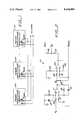
- FIG. 3a circuit schematic of the current sharing circuit of FIG. 1 as integrated with a half bridge pulse width modulated DC-DC converter.
- FIG. 1shown therein is a power system that includes a plurality of parallel coupled power conditioner modules 100 which have their outputs connected together and their returns (e.g., ground) connected together.
- the power conditionersinclude respective current sharing circuits connected to a node A.
- the voltage at the node Arepresents the average current of all the power conditioners 100, and the voltage across the resistor 25 represents the difference between (a) the current of the associated power conditioner and (b) the average current.
- the output of the operational amplifier 11is coupled to the non-inverting input of an operational amplifier 27 via a resistor 29.
- a resistor 31is connected between the node A and the inverting input of the operational amplifier 27, and a feedback resistor 33 is connected between the output of the operational amplifier 27 and its inverting input.
- a resistor 35is connected between ground and the non-inverting input of the operational amplifier 27.
- the operational amplifier 27is configured as a differential amplifier for amplifying the difference voltage developed across the resistor 25, and the value of the resistor 29 is equal to the value of the resistor 31, and with the value of the resistor 33 is equal to the value of the resistor 35.
- the gain of the operational amplifieris substantially equal to the value of the resistor 33 divided by the value of the resistor 31.
- the output of the operational amplifier 27is representative of the difference between the average load current of the associated power conditioner and the average load current for all of the power conditioners in the power system.
- the output voltage of the operational amplifier 27is zero if the load current of the associated power conditioner is equal to the average load current for all of the power conditioners in the power system.
- the voltage output of the operational amplifier 27is summed with the output voltage V out of the associated power conditioner via resistors 37, 39 which are serially connected between the output of the operational amplifier 27 and the output voltage V out of the associated power conditioner.
- the resultant voltage V fb at the node between the resistors 37, 39is a modified feedback voltage that is provided to the error amplifier of the associated power conditioner.
- the voltage V fbis called a "modified" feedback signal since in a power conditioner without a current share circuit the feedback voltage would typically be the power conditioner voltage output or some voltage representative of that voltage output.
- the current share circuitis phased such that, if the power conditioner is supplying more than the average load current, the circuit causes the feedback voltage V fb to increase.
- the error amplifier of the power conditioneris phased to reduce the power conditioner output voltage in response to an increased feedback voltage.
- FIG. 3shown therein by way of illustrative example is a schematic diagram of a half-bridge pulse width modulated (PWM) switching DC-DC power conditioner with feedback control that can be utilized with the current share circuit 10 of FIG. 2.
- the power conditionerincludes an error amplifier 111 which receives the modified feedback voltage V fb from the current share circuit 10 at its inverting input.
- a reference regulator 113provides the input for the non-inverting input of the error amplifier 111, which has its output connected to the inverting input of a comparator 115.
- the output of an oscillator 117is provided to a flip-flop 119 and a ramp generator 121.
- the output of the ramp generatorwhich is connected to the non-inverting input of the comparator 115, is controlled by the voltage V x and is synchronized to the oscillator.
- the flip-flop output and its complementare respectively provided as inputs to NOR-gates 123, 125, which have power output stages to provide the necessary power for driving the converter switches comprising power FETs 127, 129.
- the output of the comparator 115provided as inputs to both NOR-gates 123, 125.
- the outputs of the NOR-gates 123, 125are respectively connected to the ends of the primary winding of a driver transformer 131 that includes two secondary windings. Such secondary windings are connected to the gates of the power FETs 127, 129 that are serially connected between a positive voltage V in and and a negative voltage -V in .
- the positive and negative voltages ⁇ V incan be the unregulated, rectified output of an AC power source.
- the node between the power FETs 127, 129is coupled via a current sensing transformer circuit 133 to one end the the primary winding of a power output transformer 135.
- the other end of the primary winding of the output power transformer 135is connected to the node between capacitors 137, 139 that are serially connected between the positive voltage V in and the negative voltage -V in .
- the current sensing transformer circuit 133which includes diodes connected to its secondary winding, provides the voltage V x for the current share circuit 10.
- the voltage at the secondary winding of the output power transformer 135is full-wave rectified by diodes 141, 143.
- the rectified voltageis filtered by a low pass filter comprising an inductor 145 and a capacitor 147 to provide the power conditioner output V out .
- the PWM converteris a switching regulator that converts unregulated DC voltage to regulated DC voltage by varying the converter switch "on time” with respect to its period, "on time” plus “off time,” and generally operates as follows.
- a fraction of the converter output voltage V outis fed back to the error amplifier 111 via the resistor divider network in the current share circuit 10.
- the feedback voltageis modified by the current share circuit 10 to force current sharing among parallel connected converters as described above.
- the error amplifier 111is a differential amplifier that amplifies the voltage difference between the feedback voltage and the reference voltage to provide an error voltage to the comparator 115 which compares the amplified error voltage with the ramp voltage.
- the ramp voltageis a function of the converter current.
- the pulse width modulationoccurs when the ramp voltage exceeds the amplified error voltage, and the output of the comparator 115 switches from a low state to a high state.
- the comparatorswitches back to the low state when the oscillator 117 resets the ramp generator 121 and the amplified error voltage exceeds the ramp voltage.
- the modulated pulsewidth signal from the comparator 115is supplied to the steering circuit comprising the flip-flop 119 and two NOR gates 123, 125.
- the flip-flop 119steers the modulated pulsewidth signal from the comparator 115 to one of the two NOR-gates 123, 125 alternately.
- the output of the NOR gatesis followed by the drive transformer 131 which provides the necessary outputs with proper phasing and isolation required by the bridge converter FET switches 127, 129.
- the FET switches 127, 129connected in a half bridge configuration, in conjunction with the input voltages, ⁇ V in superimpose a quasi-square wave voltage across the primary of the output power transformer 13 as dictated by the pulsewidth modulated signal from the NOR gates 123, 125.
- the voltage at the output transformer 135 secondarya replica of the primary voltage, is rectified by two diodes connected in a full-wave configuration.
- a low-pass filterconsisting of an inductor and a capacitor follows the rectifiers.
- the output of the low pass filteris a low ripple DC voltage that is regulated.
- the PWM convertercan be implemented with an integrated circuit pulse width modulation controller such as the UC 3825 High Speed PWM Controller available from Unitrode Integrated Circuits, 7 Continental Boulevard., Merrimack, N.H. 03054, which includes an error amplifier.
- an integrated circuit pulse width modulation controllersuch as the UC 3825 High Speed PWM Controller available from Unitrode Integrated Circuits, 7 Continental Boulevard., Merrimack, N.H. 03054, which includes an error amplifier.
Landscapes
- Engineering & Computer Science (AREA)
- Power Engineering (AREA)
- Dc-Dc Converters (AREA)
Abstract
Description
Claims (5)
Priority Applications (1)
| Application Number | Priority Date | Filing Date | Title |
|---|---|---|---|
| US07/501,999US5164890A (en) | 1990-03-29 | 1990-03-29 | Current share scheme for parallel operation of power conditioners |
Applications Claiming Priority (1)
| Application Number | Priority Date | Filing Date | Title |
|---|---|---|---|
| US07/501,999US5164890A (en) | 1990-03-29 | 1990-03-29 | Current share scheme for parallel operation of power conditioners |
Publications (1)
| Publication Number | Publication Date |
|---|---|
| US5164890Atrue US5164890A (en) | 1992-11-17 |
Family
ID=23995898
Family Applications (1)
| Application Number | Title | Priority Date | Filing Date |
|---|---|---|---|
| US07/501,999Expired - LifetimeUS5164890A (en) | 1990-03-29 | 1990-03-29 | Current share scheme for parallel operation of power conditioners |
Country Status (1)
| Country | Link |
|---|---|
| US (1) | US5164890A (en) |
Cited By (35)
| Publication number | Priority date | Publication date | Assignee | Title |
|---|---|---|---|---|
| US5267135A (en)* | 1990-11-26 | 1993-11-30 | Nec Corporation | Power supply apparatus having interlocking operating system |
| WO1994023489A1 (en)* | 1993-03-30 | 1994-10-13 | R.O. Associates | Improved current sharing signal coupling/decoupling circuit for power converter systems |
| US5376830A (en)* | 1993-09-17 | 1994-12-27 | International Business Machines Corporation | High frequency slope compensation circuit for current programmed converter |
| US5428524A (en)* | 1994-01-21 | 1995-06-27 | Intel Corporation | Method and apparatus for current sharing among multiple power supplies |
| US5436550A (en)* | 1993-01-22 | 1995-07-25 | Tokyo, Inc. | AC-DC converter having saw-tooth wave generating circuit in active filter |
| EP0664596A1 (en)* | 1994-01-21 | 1995-07-26 | Siemens Nixdorf Informationssysteme AG | Device for the symmetrisation of currents |
| US5521809A (en)* | 1993-09-17 | 1996-05-28 | International Business Machines Corporation | Current share circuit for DC to DC converters |
| US5563540A (en)* | 1993-09-17 | 1996-10-08 | International Business Machines Corporation | Electronic switch having programmable means to reduce noise coupling |
| DE19546495A1 (en)* | 1995-12-13 | 1997-06-19 | Aeg Stromversorgungs Syst Gmbh | Equalisation of power distribution to loads e.g. for railway locomotive |
| WO1997045947A1 (en)* | 1996-05-30 | 1997-12-04 | Nokia Telecommunications Oy | Switched-mode power supply arrangement |
| US5723913A (en)* | 1994-12-06 | 1998-03-03 | Performance Controls, Inc. | High-voltage electronic switching circuit |
| US5740023A (en)* | 1996-05-24 | 1998-04-14 | Lucent Technologies Inc. | Control system for a modular power supply and method of operation thereof |
| US6009000A (en)* | 1999-02-05 | 1999-12-28 | The Aerospace Corporation | Shared-bus current sharing parallel connected current-mode DC to DC converters |
| US6285571B1 (en) | 2000-03-03 | 2001-09-04 | Linfinity Microelectronics | Method and apparatus for an efficient multiphase switching regulator |
| US6292378B1 (en) | 2000-04-07 | 2001-09-18 | Linfinity Microelectronics | Method and apparatus for programmable current sharing |
| US6346798B1 (en)* | 1999-06-07 | 2002-02-12 | Stmicroelectronics S.R.L. | Single wire current sharing control technique for the parallel/redundant operation of a plurality of PWM converters |
| RU2182741C2 (en)* | 1996-08-09 | 2002-05-20 | Гец Альстом Транспор С.А. | Electronic device for electrical energy conversion |
| US6465993B1 (en) | 1999-11-01 | 2002-10-15 | John Clarkin | Voltage regulation employing a composite feedback signal |
| RU2193226C2 (en)* | 2000-08-02 | 2002-11-20 | Герасимов Владимир Александрович | Ac voltage regulator |
| WO2002095917A3 (en)* | 2001-05-18 | 2003-06-19 | Siemens Ag | Electricity supply having a high degree of efficiency |
| US6642631B1 (en)* | 2000-10-17 | 2003-11-04 | Semiconductor Components Industries Llc | Circuit and method of direct duty cycle current sharing |
| US20040036452A1 (en)* | 2002-06-28 | 2004-02-26 | Brooks Steven W. | Method and apparatus for load sharing in a multiphase switching power converter |
| US20040041543A1 (en)* | 2002-06-28 | 2004-03-04 | Brooks Steven W. | Method and apparatus for auto-interleaving synchronization in a multiphase switching power converter |
| US20040041544A1 (en)* | 2002-06-28 | 2004-03-04 | Brooks Steven W. | Method and apparatus for dithering auto-synchronization of a multiphase switching power converter |
| US20060171182A1 (en)* | 2005-01-28 | 2006-08-03 | Kasemsan Siri | Solar array inverter with maximum power tracking |
| US20070070664A1 (en)* | 2005-09-27 | 2007-03-29 | Keming Chen | Bi-directional current sensing circuit |
| WO2007050739A1 (en)* | 2005-10-25 | 2007-05-03 | Microchip Technology Incorporated | Using pulse width modulation in the control of load sharing between paralleled power supplies |
| CN100464478C (en)* | 2006-11-23 | 2009-02-25 | 广州擎天实业有限公司 | Parallel democratic bus uniform flow constant current method and its device |
| KR101047338B1 (en) | 2010-12-01 | 2011-07-07 | 주식회사 코디에스 | Parallel operation power supply using module current control loop |
| US8093839B2 (en) | 2008-11-20 | 2012-01-10 | Microsemi Corporation | Method and apparatus for driving CCFL at low burst duty cycle rates |
| US8358082B2 (en) | 2006-07-06 | 2013-01-22 | Microsemi Corporation | Striking and open lamp regulation for CCFL controller |
| US8730695B1 (en) | 2006-03-02 | 2014-05-20 | Ocean Server Technology, Inc. | Load balancing method and system to scale DC output power by temperature of parallel DC power supplies |
| US9857812B2 (en) | 2014-08-01 | 2018-01-02 | General Electric Company | Systems and methods for advanced diagnostic in modular power converters |
| CN105958469B (en)* | 2016-06-15 | 2018-08-24 | 厦门科灿信息技术有限公司 | A kind of programmable multi-machine parallel connection power-supply system is synchronous and current equalizing method |
| CN120474339A (en)* | 2025-07-16 | 2025-08-12 | 西安航天民芯科技有限公司 | Switch power supply for controlling load current sharing |
Citations (5)
| Publication number | Priority date | Publication date | Assignee | Title |
|---|---|---|---|---|
| US4276590A (en)* | 1979-04-30 | 1981-06-30 | The Perkin-Elmer Corporation | Current sharing modular power system |
| US4425613A (en)* | 1981-05-26 | 1984-01-10 | Sperry Corporation | Forced load sharing circuit for inverter power supply |
| US4717833A (en)* | 1984-04-30 | 1988-01-05 | Boschert Inc. | Single wire current share paralleling of power supplies |
| US4841161A (en)* | 1985-07-16 | 1989-06-20 | Italtel Societa Italiana Telecomunicazioni S.P.A | Monitoring circuit for control means and selective breakaway means in modular supply systems |
| US4924170A (en)* | 1989-01-03 | 1990-05-08 | Unisys Corporation | Current sharing modular power supply |
- 1990
- 1990-03-29USUS07/501,999patent/US5164890A/ennot_activeExpired - Lifetime
Patent Citations (5)
| Publication number | Priority date | Publication date | Assignee | Title |
|---|---|---|---|---|
| US4276590A (en)* | 1979-04-30 | 1981-06-30 | The Perkin-Elmer Corporation | Current sharing modular power system |
| US4425613A (en)* | 1981-05-26 | 1984-01-10 | Sperry Corporation | Forced load sharing circuit for inverter power supply |
| US4717833A (en)* | 1984-04-30 | 1988-01-05 | Boschert Inc. | Single wire current share paralleling of power supplies |
| US4841161A (en)* | 1985-07-16 | 1989-06-20 | Italtel Societa Italiana Telecomunicazioni S.P.A | Monitoring circuit for control means and selective breakaway means in modular supply systems |
| US4924170A (en)* | 1989-01-03 | 1990-05-08 | Unisys Corporation | Current sharing modular power supply |
Cited By (52)
| Publication number | Priority date | Publication date | Assignee | Title |
|---|---|---|---|---|
| US5267135A (en)* | 1990-11-26 | 1993-11-30 | Nec Corporation | Power supply apparatus having interlocking operating system |
| US5436550A (en)* | 1993-01-22 | 1995-07-25 | Tokyo, Inc. | AC-DC converter having saw-tooth wave generating circuit in active filter |
| WO1994023489A1 (en)* | 1993-03-30 | 1994-10-13 | R.O. Associates | Improved current sharing signal coupling/decoupling circuit for power converter systems |
| US5428523A (en)* | 1993-03-30 | 1995-06-27 | Ro Associates | Current sharing signal coupling/decoupling circuit for power converter systems |
| US5376830A (en)* | 1993-09-17 | 1994-12-27 | International Business Machines Corporation | High frequency slope compensation circuit for current programmed converter |
| US5521809A (en)* | 1993-09-17 | 1996-05-28 | International Business Machines Corporation | Current share circuit for DC to DC converters |
| US5563540A (en)* | 1993-09-17 | 1996-10-08 | International Business Machines Corporation | Electronic switch having programmable means to reduce noise coupling |
| US5428524A (en)* | 1994-01-21 | 1995-06-27 | Intel Corporation | Method and apparatus for current sharing among multiple power supplies |
| EP0664596A1 (en)* | 1994-01-21 | 1995-07-26 | Siemens Nixdorf Informationssysteme AG | Device for the symmetrisation of currents |
| DE4401728A1 (en)* | 1994-01-21 | 1995-08-03 | Siemens Nixdorf Inf Syst | Current balancing circuit |
| US5723913A (en)* | 1994-12-06 | 1998-03-03 | Performance Controls, Inc. | High-voltage electronic switching circuit |
| DE19546495A1 (en)* | 1995-12-13 | 1997-06-19 | Aeg Stromversorgungs Syst Gmbh | Equalisation of power distribution to loads e.g. for railway locomotive |
| US5740023A (en)* | 1996-05-24 | 1998-04-14 | Lucent Technologies Inc. | Control system for a modular power supply and method of operation thereof |
| WO1997045947A1 (en)* | 1996-05-30 | 1997-12-04 | Nokia Telecommunications Oy | Switched-mode power supply arrangement |
| AU721649B2 (en)* | 1996-05-30 | 2000-07-13 | Nokia Telecommunications Oy | Switched-mode power supply arrangement |
| US6121759A (en)* | 1996-05-30 | 2000-09-19 | Nokia Telecommunications Oy | Arrangement of switched-mode power supplies connected in parallel without a separation diode |
| RU2188495C2 (en)* | 1996-05-30 | 2002-08-27 | Нокиа Телекоммьюникейшнз Ой | Power supply circuit with changeable operating conditions |
| CN1075274C (en)* | 1996-05-30 | 2001-11-21 | 诺基亚电信公司 | Switched-mode power supply arrangement |
| RU2182741C2 (en)* | 1996-08-09 | 2002-05-20 | Гец Альстом Транспор С.А. | Electronic device for electrical energy conversion |
| US6009000A (en)* | 1999-02-05 | 1999-12-28 | The Aerospace Corporation | Shared-bus current sharing parallel connected current-mode DC to DC converters |
| US6346798B1 (en)* | 1999-06-07 | 2002-02-12 | Stmicroelectronics S.R.L. | Single wire current sharing control technique for the parallel/redundant operation of a plurality of PWM converters |
| US6465993B1 (en) | 1999-11-01 | 2002-10-15 | John Clarkin | Voltage regulation employing a composite feedback signal |
| US6285571B1 (en) | 2000-03-03 | 2001-09-04 | Linfinity Microelectronics | Method and apparatus for an efficient multiphase switching regulator |
| US6292378B1 (en) | 2000-04-07 | 2001-09-18 | Linfinity Microelectronics | Method and apparatus for programmable current sharing |
| RU2193226C2 (en)* | 2000-08-02 | 2002-11-20 | Герасимов Владимир Александрович | Ac voltage regulator |
| US6642631B1 (en)* | 2000-10-17 | 2003-11-04 | Semiconductor Components Industries Llc | Circuit and method of direct duty cycle current sharing |
| WO2002095917A3 (en)* | 2001-05-18 | 2003-06-19 | Siemens Ag | Electricity supply having a high degree of efficiency |
| US7109691B2 (en) | 2002-06-28 | 2006-09-19 | Microsemi Corporation | Systems for auto-interleaving synchronization in a multiphase switching power converter |
| US20040041543A1 (en)* | 2002-06-28 | 2004-03-04 | Brooks Steven W. | Method and apparatus for auto-interleaving synchronization in a multiphase switching power converter |
| US20040041544A1 (en)* | 2002-06-28 | 2004-03-04 | Brooks Steven W. | Method and apparatus for dithering auto-synchronization of a multiphase switching power converter |
| US6836103B2 (en) | 2002-06-28 | 2004-12-28 | Microsemi Corporation | Method and apparatus for dithering auto-synchronization of a multiphase switching power converter |
| US6965219B2 (en) | 2002-06-28 | 2005-11-15 | Microsemi Corporation | Method and apparatus for auto-interleaving synchronization in a multiphase switching power converter |
| US20060028850A1 (en)* | 2002-06-28 | 2006-02-09 | Brooks Steven W | Systems for auto-interleaving synchronization in a multiphase switching power converter |
| US7005835B2 (en) | 2002-06-28 | 2006-02-28 | Microsemi Corp. | Method and apparatus for load sharing in a multiphase switching power converter |
| US20040036452A1 (en)* | 2002-06-28 | 2004-02-26 | Brooks Steven W. | Method and apparatus for load sharing in a multiphase switching power converter |
| US7193872B2 (en) | 2005-01-28 | 2007-03-20 | Kasemsan Siri | Solar array inverter with maximum power tracking |
| US20060171182A1 (en)* | 2005-01-28 | 2006-08-03 | Kasemsan Siri | Solar array inverter with maximum power tracking |
| US20070070664A1 (en)* | 2005-09-27 | 2007-03-29 | Keming Chen | Bi-directional current sensing circuit |
| US7643321B2 (en)* | 2005-09-27 | 2010-01-05 | Gm Global Technology Operations, Inc. | Bi-directional current sensing circuit |
| WO2007050739A1 (en)* | 2005-10-25 | 2007-05-03 | Microchip Technology Incorporated | Using pulse width modulation in the control of load sharing between paralleled power supplies |
| CN101297252B (en)* | 2005-10-25 | 2010-12-15 | 密克罗奇普技术公司 | Using pulse width modulation in the control of load sharing between paralleled power supplies |
| KR101010016B1 (en) | 2005-10-25 | 2011-01-21 | 마이크로칩 테크놀로지 인코포레이티드 | Use of Pulse Width Modulation for Load Sharing Control Between Paralleled Power Supplies |
| US8730695B1 (en) | 2006-03-02 | 2014-05-20 | Ocean Server Technology, Inc. | Load balancing method and system to scale DC output power by temperature of parallel DC power supplies |
| US8358082B2 (en) | 2006-07-06 | 2013-01-22 | Microsemi Corporation | Striking and open lamp regulation for CCFL controller |
| CN100464478C (en)* | 2006-11-23 | 2009-02-25 | 广州擎天实业有限公司 | Parallel democratic bus uniform flow constant current method and its device |
| US8093839B2 (en) | 2008-11-20 | 2012-01-10 | Microsemi Corporation | Method and apparatus for driving CCFL at low burst duty cycle rates |
| CN102487215A (en)* | 2010-12-01 | 2012-06-06 | 寇地斯股份有限公司 | Power device using module current to control parallel running of circuit |
| KR101047338B1 (en) | 2010-12-01 | 2011-07-07 | 주식회사 코디에스 | Parallel operation power supply using module current control loop |
| CN102487215B (en)* | 2010-12-01 | 2016-02-17 | 寇地斯股份有限公司 | Utilize the parallel running supply unit of blocks current control circuit |
| US9857812B2 (en) | 2014-08-01 | 2018-01-02 | General Electric Company | Systems and methods for advanced diagnostic in modular power converters |
| CN105958469B (en)* | 2016-06-15 | 2018-08-24 | 厦门科灿信息技术有限公司 | A kind of programmable multi-machine parallel connection power-supply system is synchronous and current equalizing method |
| CN120474339A (en)* | 2025-07-16 | 2025-08-12 | 西安航天民芯科技有限公司 | Switch power supply for controlling load current sharing |
Similar Documents
| Publication | Publication Date | Title |
|---|---|---|
| US5164890A (en) | Current share scheme for parallel operation of power conditioners | |
| US5777519A (en) | High efficiency power amplifier | |
| US5541828A (en) | Multiple output converter with continuous power transfer to an output and with multiple output regulation | |
| US4628426A (en) | Dual output DC-DC converter with independently controllable output voltages | |
| US6150803A (en) | Dual input, single output power supply | |
| US6850045B2 (en) | Multi-phase and multi-module power system with a current share bus | |
| US5724237A (en) | Apparatus and method for sharing a load current among frequency-controlled D.C.-to-D.C. converters | |
| US5805432A (en) | Resonant DC-DC converter capable of controlling by pulse width modulation | |
| US5504418A (en) | Full shunt boost switching voltage limiter for solar panel array | |
| US5359280A (en) | Bilateral power converter for a satellite power system | |
| US3970916A (en) | Circuit arrangement for producing an alternating voltage | |
| US5576940A (en) | Front-end power converter for distributed power systems | |
| EP4030609B1 (en) | Multi-phase hybrid converter | |
| EP0500789B1 (en) | An uninterrupted power supply system having improved power factor correction circuit | |
| US6768658B2 (en) | DC-DC power supply with at least two paralleled converters and current share method for same | |
| US7276886B2 (en) | Dual buck-boost converter with single inductor | |
| US5397976A (en) | Control system for voltage controlled bilateral current source | |
| EP1296442A2 (en) | Apparatus for improving stability and dynamic response of half-bridge converter | |
| US5646513A (en) | Dynamic loop compensator for continuous mode power converters | |
| US5253157A (en) | Half-bridge inverter with capacitive voltage equalizer | |
| US4149233A (en) | Circuit for automatic load sharing in parallel converter modules | |
| US20030007376A1 (en) | Simple and efficient isolated switching regulator for fast transient loads | |
| US6249411B1 (en) | Over-voltage protection circuit and method for preventing system shutdown in a power system employing multiple power supplies | |
| US4866591A (en) | Regulated transformer rectifier unit | |
| US4502104A (en) | Bootstrapped AC-DC power converter |
Legal Events
| Date | Code | Title | Description |
|---|---|---|---|
| AS | Assignment | Owner name:HUGHES AIRCRAFT COMPANY, A CORP. OF DE, CALIFOR Free format text:ASSIGNMENT OF ASSIGNORS INTEREST.;ASSIGNORS:NAKAGAWA, SAM;FONG, BAILEY M.;REEL/FRAME:005272/0478 Effective date:19900325 | |
| STCF | Information on status: patent grant | Free format text:PATENTED CASE | |
| FPAY | Fee payment | Year of fee payment:4 | |
| AS | Assignment | Owner name:HUGHES ELECTRONICS CORPORATION, CALIFORNIA Free format text:ASSIGNMENT OF ASSIGNORS INTEREST;ASSIGNORS:HE HOLDINGS INC.;HUGHES ELECTRONICS, FORMERLY KNOWN AS HUGHES AIRCRAFT COMPANY;REEL/FRAME:009342/0796 Effective date:19971217 | |
| FPAY | Fee payment | Year of fee payment:8 | |
| FEPP | Fee payment procedure | Free format text:PAYOR NUMBER ASSIGNED (ORIGINAL EVENT CODE: ASPN); ENTITY STATUS OF PATENT OWNER: LARGE ENTITY Free format text:PAYER NUMBER DE-ASSIGNED (ORIGINAL EVENT CODE: RMPN); ENTITY STATUS OF PATENT OWNER: LARGE ENTITY | |
| FPAY | Fee payment | Year of fee payment:12 |