US5164732A - Highway vehicle identification system with high gain antenna - Google Patents
Highway vehicle identification system with high gain antennaDownload PDFInfo
- Publication number
- US5164732A US5164732AUS07/446,234US44623489AUS5164732AUS 5164732 AUS5164732 AUS 5164732AUS 44623489 AUS44623489 AUS 44623489AUS 5164732 AUS5164732 AUS 5164732A
- Authority
- US
- United States
- Prior art keywords
- roadway
- antenna
- transponder
- lane
- collinear
- Prior art date
- Legal status (The legal status is an assumption and is not a legal conclusion. Google has not performed a legal analysis and makes no representation as to the accuracy of the status listed.)
- Expired - Lifetime
Links
Images


Classifications
- G—PHYSICS
- G07—CHECKING-DEVICES
- G07B—TICKET-ISSUING APPARATUS; FARE-REGISTERING APPARATUS; FRANKING APPARATUS
- G07B15/00—Arrangements or apparatus for collecting fares, tolls or entrance fees at one or more control points
- G07B15/06—Arrangements for road pricing or congestion charging of vehicles or vehicle users, e.g. automatic toll systems
- G07B15/063—Arrangements for road pricing or congestion charging of vehicles or vehicle users, e.g. automatic toll systems using wireless information transmission between the vehicle and a fixed station
- B—PERFORMING OPERATIONS; TRANSPORTING
- B61—RAILWAYS
- B61L—GUIDING RAILWAY TRAFFIC; ENSURING THE SAFETY OF RAILWAY TRAFFIC
- B61L25/00—Recording or indicating positions or identities of vehicles or trains or setting of track apparatus
- B61L25/02—Indicating or recording positions or identities of vehicles or trains
- B61L25/04—Indicating or recording train identities
- B61L25/048—Indicating or recording train identities using programmable tags
- G—PHYSICS
- G06—COMPUTING OR CALCULATING; COUNTING
- G06K—GRAPHICAL DATA READING; PRESENTATION OF DATA; RECORD CARRIERS; HANDLING RECORD CARRIERS
- G06K19/00—Record carriers for use with machines and with at least a part designed to carry digital markings
- G06K19/06—Record carriers for use with machines and with at least a part designed to carry digital markings characterised by the kind of the digital marking, e.g. shape, nature, code
- G06K19/067—Record carriers with conductive marks, printed circuits or semiconductor circuit elements, e.g. credit or identity cards also with resonating or responding marks without active components
- G06K19/07—Record carriers with conductive marks, printed circuits or semiconductor circuit elements, e.g. credit or identity cards also with resonating or responding marks without active components with integrated circuit chips
- G06K19/0723—Record carriers with conductive marks, printed circuits or semiconductor circuit elements, e.g. credit or identity cards also with resonating or responding marks without active components with integrated circuit chips the record carrier comprising an arrangement for non-contact communication, e.g. wireless communication circuits on transponder cards, non-contact smart cards or RFIDs
- G—PHYSICS
- G06—COMPUTING OR CALCULATING; COUNTING
- G06K—GRAPHICAL DATA READING; PRESENTATION OF DATA; RECORD CARRIERS; HANDLING RECORD CARRIERS
- G06K7/00—Methods or arrangements for sensing record carriers, e.g. for reading patterns
- G06K7/0008—General problems related to the reading of electronic memory record carriers, independent of its reading method, e.g. power transfer
- G—PHYSICS
- G07—CHECKING-DEVICES
- G07C—TIME OR ATTENDANCE REGISTERS; REGISTERING OR INDICATING THE WORKING OF MACHINES; GENERATING RANDOM NUMBERS; VOTING OR LOTTERY APPARATUS; ARRANGEMENTS, SYSTEMS OR APPARATUS FOR CHECKING NOT PROVIDED FOR ELSEWHERE
- G07C9/00—Individual registration on entry or exit
- G07C9/20—Individual registration on entry or exit involving the use of a pass
- G07C9/28—Individual registration on entry or exit involving the use of a pass the pass enabling tracking or indicating presence
- G—PHYSICS
- G08—SIGNALLING
- G08G—TRAFFIC CONTROL SYSTEMS
- G08G1/00—Traffic control systems for road vehicles
- G08G1/01—Detecting movement of traffic to be counted or controlled
- G08G1/017—Detecting movement of traffic to be counted or controlled identifying vehicles
Definitions
- the inventionrelates to an identification system suitable for identifying objects from a remote interrogation station. More specifically, the invention provides an electronic identification device including a logic circuit and a memory, a trigger circuit and a transmitter positioned on an object and a remote interrogation station including a receiver and data processor, together with means for remotely programming the electronic identification device with transit information when the object is moving relative to the interrogation station.
- the inventionalso includes a system and apparatus for identifying vehicles traveling along multi-lane bidirectional highways by using a roadway antenna connected to the receiver of the remote interrogation station.
- the roadway antennacomprises an antenna array traversing the highway lanes, and includes a collinear antenna array positioned in a reflector shield filled with a dielectric and buried in a flush-mount relationship with the roadway surface.
- an identification systemwherein moving objects such as railroad cars, passing an interrogation station, identify themselves for both accounting and control purposes. Such a system would also be applicable to boats, trucks, shipping containers, mail bags, pallets, etc. As well as these commercial applications, there is also a need for an identification system for monitoring animals in their natural habitat, including both fish and birds. The system could be applicable for identification of humans, for control and security purposes, the identification of livestock, and many other uses. In addition to the above uses, the ability to read, write, delete or modify data in a digital form makes the system applicable to a variety of uses, an example of which is a credit card. In this case, the system serves as a portable interrogable memory for information such as a credit balance.
- transponder systemhaving a high gain antenna but with broad transverse coverage to ensure that transponder communication can take place between an interrogation station and an information and identity storage system carried by a highway vehicle.
- the present inventionprovides an electronic identification system that can store both fixed and changing information on a moving object, such as a railroad car, without physical contact and while the object is moving at relatively high speeds. Furthermore, a portion of the information stored on the object can be protected from accidental erasure so that portion cannot be changed without further steps being taken.
- the systemprovides the car's identity and other pertinent information relating to the car. Some of the information is protected from erasure, such as the identification number, the type of car and loading limits. Other information, such as destination, contents, special handling considerations, etc., can be reprogrammed remotely by an interrogation station.
- a memorythat can be read and changed and has a number of separate pages to store information is located on the object.
- Different interrogation stationscan then be placed to send encoded interrogation signals to read individual pages of information. Some pages may be protected from erasure as they contain fixed information, while other pages may be remotely changed as desired.
- By utilizing separate pages in the memory, and more than one interrogation stationmore information can be gathered in a shorter space of time, thus allowing higher relative speeds between the object and the interrogation station.
- the information gathered by the interrogation stationsmay be transmitted in a computer-compatible format for storage and transmission by existing data communication systems.
- the electronic identification system of the present inventionhas an information and identity storage device including a logic circuit and memory, trigger circuit and a transmitter located on the object, with the trigger circuit operating on low power.
- the transmitterUpon being triggered by a signal from a remote interrogation station, the transmitter transmits the data into memory in a short series of transmissions.
- Power for the transmitteris provided by battery but can include other sources of power, such as an inertial generator, electromagnetic generation, induction, visible or infrared light, or by combinations of these power sources.
- Moving objectscan generate power for the transmitter from movement or vibration in a gravitational field. This technique can also be used to extend the life of the battery.
- the interrogation stationas well as sending a signal to trigger the trigger circuit, also has a pulse sequence generator to program the memory on the object and a receiver to receive the data from the memory on the object.
- an absolute time source in the information and identity storage deviceprovides for synchronization between the transmitter and the receiver and allows the use of a non-return to zero (NRZ) code format.
- NRZnon-return to zero
- a free running clockcan be used in the system and synchronization can be effected by choice of a suitable code format and appropriate processing in the decoding unit.
- This systemhas the additional advantage of allowing the clock oscillator to be gated off between interrogations with further savings in quiescent power consumption
- the data transfer rate for the transmittershould be sufficient to allow for the relative velocity between the object to be identified and the interrogation station.
- the memory bank associated with the information and identity storage device on the vehiclestores two hundred fifty six bits divided into four sixty four bit pages.
- the first pagecould contain the most important information including the identity of the vehicle and can be read at speeds of up to 320 km./hr. (160 m.p.h.).
- the other pagescan be read by the same interrogation station at lower speeds.
- Thirty four bits of the first sixty four bit page of the memorycan be "write-protected" to prevent erasure.
- the "write-protected" portion of the memory bankcan be reprogrammed for use on a different vehicle without physical alterations.
- these "write-protected" bitscan be reprogrammed by illuminating a light-activated switch located on the information and identity storage device.
- a microwave signalis transmitted and received between the transmitter and receiver.
- Other radio frequency, optical or inductive communication schemesare feasible.
- an interrogation stationreads at a distance of up to five meters, but this distance can be increased to several kilometers for different uses, or reduced for other uses.
- the information and identity storage deviceshave to be suitably packaged for protection against weather and environmental conditions and have antennas to allow transmission and receipt of coded signals in suitable locations.
- the present inventionalso provides an electronic identification system for remotely storing information on an object, and remotely retrieving information from the object.
- the electronic identification systemincludes, in combination, an information and identity storage device located on the object, and at least one interrogation station located remotely from the object.
- the interrogation stationis adapted to read data from the information and identity storage device as well as to program it without physical contact.
- the information and identity storage devicecomprises memory means for storing information and identity data, and protect means for protecting a portion of the memory means against accidental erasure.
- Logic circuit means for producing a predetermined coded signal representing the information and identity data stored in the memory meanshas a remote non-contact means for programming the portion of the memory means not protected by the protect means.
- Transmitter means for transmitting the coded signalis coupled to trigger circuit means which, when triggered, causes the coded signal to be transmitted.
- a battery power sourceenergizes the other portions of the information and identity storage device.
- the interrogation stationcomprises interrogation signal means for triggering the logic circuit means in the information and identity storage device and pulse sequence generating means for programming the portion of the memory means on the information and identity storage device not protected by the protect means.
- the interrogation stationalso has receiver means for receiving the coded signal from the information and identity storage device and synchronization means between the information and identity storage device, and the receiver means. Decoder means for decoding the coded signal, verifies the accuracy of the coded signal, and recovers the information and identity data stored in the memory means of the information and identity storage device and transmitted to the interrogation station.
- a first antennais provided in the logic circuit means to pick up an interrogation signal, and a second antenna is adapted to transmit the coded signal from the transmitter means.
- An absolute time sourceis provided integral with the information and identity storage device, together with synchronization means between this time source and the receiver means.
- the memory meanshas the ability to store a plurality of pages representing the information and identity data, and the logic circuit means can select data from the plurality of pages upon receipt of predetermined timed interrogation pulses from the interrogation station.
- the decoder meansverifies the accuracy of the coded signal by including an integral count of the number of zeros in the coded signal.
- a light-activated switch integral with the protect meansis provided in one embodiment which, when illuminated, permits the portion of the memory means protected by the protect means to be erased and reprogrammed.
- a wheel contact signal meansis provided for use on a railroad car to indicate arrival of each car at the interrogation station.
- a particularly important additional embodiment of the vehicular identification system and the equipment disclosed hereinis monitoring highway vehicles, motion on multi-lane highways such as toll roads and expressways.
- states of the United Stateshave found it necessary to control heavy truck traffic on interstate highways within their borders.
- speedssuch as 70 m.p.h.
- 120 ft./sec. or 72 m.p.h.will be used, although higher speeds can be accommodated at increased data rates.
- radio frequency signals from the road surfaceto high speed vehicles, such as trucks travelling along bidirectional multi-lane highways, presents appreciable application difficulties.
- itis necessary to transmit and receive signals from the road surface to each lane of the highway and individually identify each vehicle, although they may be closely spaced, as they travel over a transmitting and receiving antenna located at the highway surface.
- the present inventiondetects vehicles by transmitting an interrogation signal from the road surface to a transponder or information and identity storage unit located on the vehicle, as described herein.
- a transmitting meanssuch as a radio frequency antenna and/or magnetic loop
- shallow groovesare typically cut in the road surface.
- the loop and/or antennais placed in the groove and effectively sealed or potted in the groove, thereby restoring the original highway surface.
- the invention disclosed hereinutilizes either low or high radio frequency transmissions from the road surface to the vehicle with high frequency transmissions for the reply.
- the preferred embodimentuses high frequency electromagnetic transmission in both directions, thereby avoiding the necessity of using loops in each lane of the highway being monitored.
- a portion of the invention disclosedallows all lanes to be monitored by a single set of antennas traversing them. This approach greatly simplifies installation of antennas, because a single transverse groove formed in the roadway replaces multiple cuts, which otherwise would be needed to install a loop in each monitored lane.
- the inventionfurther includes a collinear antenna array operating typically at 915 MHz., used to communicate with vehicles going in opposite directions in multi-lane highways.
- a collinear antenna arrayoperating typically at 915 MHz., used to communicate with vehicles going in opposite directions in multi-lane highways.
- the use of a multiple element collinear dipoleis advantageous in that radiation is concentrated at right angles to the array axis.
- the collinear dipole radiation patternis oriented with maxima in a radial direction from the array axis.
- the collinear dipole antenna arrayprovides a relatively constant transverse beam across all lanes of the highway, eliminating the possibility of weak signals at the outer edge of the roadway.
- the materials used for highway constructionhave widely varying electrical properties from one geographic region to another. This results in varying amounts of signal attenuation and field pattern distortion for antennas buried in the roadway.
- the antennaIn order to provide uniform performance at all locations, it is therefore necessary to electrically isolate the antenna from the roadway and to bury it in a medium of known characteristics. This is achieved by placing the antenna in a conductive channel filled with an epoxy or polyester resin of known dielectric properties. Further, by careful selection of the channel dimensions and dielectric properties, the radiation from the antenna in the upward direction can be maximized. In particular, mounting the antenna array at critical distances with respect to the open side of the channel has provided at least a three decibel signal gain in concentrating the radiation pattern in the direction of the open channel.
- Use of the dielectric materialin addition to enhancing signal transmission, provides physical protection for the antenna array including the exclusion of water and/or structurally protecting the antenna-radiating surfaces from impact loads due to vehicular tires traversing the groove.
- FIG. 1is a block diagram illustrating an electronic identity system having an information and identity storage device and an interrogation station and embodying the present invention
- FIG. 2is a schematic diagram illustrating one embodiment of a vibrationally driven power source for the information and identity storage device of FIG. 1;
- FIG. 3is a block diagram of a logic circuit in the information and identity storage device of FIG. 1;
- FIG. 4is a schematic diagram of a microwave triggered circuit of the information and identity storage device of FIG. 1;
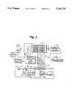
- FIG. 5is a block diagram of the interrogation station of FIG. 1;
- FIG. 6is a block diagram showing the coded signal receiver of the interrogation station of FIG. 5;
- FIG. 7is a diagram of the identification system of the invention as installed on a bidirectional, four lane highway, particularly showing the location of individual lane triggering and receiver antennas;
- FIG. 8Ashows a single lane portion of the four lane highway of the type shown in FIG. 7 having positioned therein a 130 kHz. triggering loop and a 2450 MHz. leaky coax antenna;
- FIG. 8Bshows another single lane portion of the four lane highway of the type shown in FIG. 7 having positioned therein a 130 kHz. triggering loop antenna and a 915 MHz. collinear array receiving antenna;
- FIG. 8Cshows a single lane portion of the four lane highway of the type shown in FIG. 7 having positioned therein a 915 MHz. collinear array, triggering pulse transmitting and a 915 MHz. collinear array data receiving antenna;
- FIG. 8Dshows a single lane portion of the four lane highway of the type shown in FIG. 7 having positioned therein a single 915 MHz. collinear array antenna for interrogation, transponder triggering, and transponder signal receiving through the use of a directional coupler;
- FIG. 9is an isometric view of the antenna and a reflective shield or channel housing embodying the present invention, showing details of the positioning of the channel in a roadway of a highway and the position of the antenna in the channel;
- FIG. 9Ais an isometric view of the collinear array antenna of FIG. 9, showing further details of its construction
- FIG. 9Bis an additional depiction of a portion of the collinear array of FIG. 9A, showing two complete elements and a partial element constructed from coaxial cable;
- FIG. 9Cis a graphic depiction of the current distribution in the center conductor of the coaxial cable elements of the array of FIG. 9B;
- FIG. 9Dis a further graphic depiction of the current distribution in the sheath of the coaxial cable elements of the antenna of FIG. 9B;
- FIG. 10is a sectional view taken substantially along line 10--10 of FIG. 9, showing details of the collinear array antenna and the reflecting shield;
- FIG. 10Ais a partly sectional view of the collinear array antenna of FIG. 8D, in an operative position showing details of the radiation signal pattern of the collinear array antenna in a direction parallel with the collinear array;
- FIG. 10Bis an elevational view of the roadway of FIG. 9, showing the pattern of radiated energy from the collinear array antenna and reflecting shield of FIG. 9;
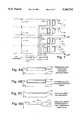
- FIG. 11is a diagrammatic representation of the sequence of triggering and data pulses transmitted and received by an interrogation station positioned adjacent a fourth lane of a four lane highway;
- FIG. 12is an isometric view of one form of a leaky coax radiating element.
- an electronic identification system 8includes a transponder or identification and identity storage device 10 and a fixed transponder or interrogation station 11.
- the information and identity storage device 10includes a power source 12, a logic circuit and a memory 13, a receiver and trigger circuit 14 with a first antenna 15, a radio frequency transmitter 16 and a second antenna 17.
- the interrogation station 11includes a receiver 18 with an antenna 19 of an antenna array, a decoder 20, a data processor 21, which provides data format memory and control functions, and a trigger interrogation pulse sequence generator and a transmitter 22 with an antenna 23.
- the data processor 21aids in the decoding process, formats the data for communication with a central data processing unit (not shown) and generally controls the functions of the interrogation station 11. In general, the complexity of the data processor 21 depends on the particular function which the electronic identification system 8 is required to perform.
- the power from the power source 12 for data retention in the memory of the information and identity storage device 10must be present at all times unless an EEROM is used and so a battery is required.
- the batterycould be supplemented by other power sources including energy transfer from inductive or radio frequency energy fields, of which several examples exist in prior art, or inertial field generation as described herein.
- the power requirementsare such that available batteries could provide up to a 20 year operational lifetime without supplemental sources of energy.
- a means for producing power for data transmissionis from the inertial field.
- FIG. 2illustrates an inertial energy generator where electric power is derived from the vibration or vertical movement of the moving object.
- a small mass 30is shown mounted in a frame 31 on one end of a resilient strip 32.
- Piezoelectric material 33is bonded to each side of the strip 32, and a movement of the mass 30, causing deflection of the strip 32, generates an alternating voltage.
- Leads 34 from the piezoelectric material 33feed to a circuit where rectification and doubling of the voltage is performed by the diodes 35, 36 and the energy storage capacitors 37, 38.
- an ordinary full-wave or half-wave rectifiermay be used if the higher voltage is not required.
- the direct current energyeither can be stored in the capacitors 37, 38 or in a rechargeable battery 39.
- a means for limiting the maximum voltageis provided in the form of a Zener diode 40, by a number of diodes in series, or by a voltage regulator circuit.
- the contents of the memoryare maintained by the battery power source 12 which provides sufficient energy to the transmitter 16 so that the coded signal is completely transmitted before the stored power drops low enough to stop the data transmission.
- the transmitter 16draws little power from the power source 12, in its quiescent state, allowing excess generated energy form the power source 12 to be stored for later transmission.
- the data to be transmitted from the information and identity storage device 10must be formatted in such a way that the desired information is conveyed accurately. While the following scheme is the preferred embodiment for marking railroad cars, a number of variations are possible. In general, the data will contain coded information to designate the owner of the car and the car's serial number in a protected portion of the memory.
- Data bitscan be coded in various ways. For North American railroad applications, where cars associated with various owners are intermixed, a code is allocated to the protected portion of the memory frame as follows:
- the data code streamcontains either a means of self-synchronization relying on the code format, or an external or inherent method of synchronization is provided.
- synchronization in some formis provided at the interrogation station 11 to clock the identification device 10.
- An alternative solutionis to provide an absolute time source such as a clock, with the identification device 10.
- the clockshould be stable enough so that synchronization of the second independent clock in the interrogation station 11 is maintained within a single bit interval for the period of time required to transmit the coded signal from the moving information and identity storage device 10 to the stationary interrogation station 11.
- the availability of low cost, accurate timing crystals for wristwatch manufacturemake the use of a non-return to zero (NRZ) code feasible for the code signal since the timing is predictable enough for data recovery.
- the low power consumption of these devicesallows lifetimes of up to 20 years on available batteries.
- One operating feature of the information and identity storage device 10is the code rate employed for the coded signal.
- High code ratesallow for many read operations at high vehicle speeds, but are more difficult to decode and consume more power.
- Typical microwave antennasallow a reading window of about 300 meters. A transmitter spends about 3.5 milliseconds in this window when traveling at 320 km./hr. Assuming at least three transmissions to be received, the total time for each transmission would be about one millisecond.
- a typical transmissioncomprises eight preamble bits and sixty four data bits so that a sufficient code rate is about 64 kHz. Doubling the frequency of a watch crystal provides a convenient rate of 65.5 kHz. with acceptably low power.
- the transmittercan be read approximately ten times with consequent improvement in accuracy.
- the maximum transponder carrying vehicle speedis 80 km./hr., which is more than adequate for those locations at which this quantity of information is required.
- spacing of information and identity storage devices 10 on adjacent railway carscan be of the order of a meter without any difficulty.
- Increased data rates for use with high speed vehicles or vehicles traveling multiple lane roadways or trackscan be provided by the transponder 10 and interrogator or reader 11 disclosed herein, and will be later described.
- FIG. 3A block diagram of the logic circuit 13 is shown in FIG. 3.
- the logic circuit 13will be familiar to those skilled in the art.
- the entire information and identity storage device 10is realized in a single CMOS integrated circuit or circuits.
- the trigger circuit 14resets the flip-flop 52 and the counters 53 and 54 and auxiliary counter 55 are allowed to count.
- Counter 54sequentially selects memory addresses which cause the contents of the preamble store 56 and the first memory page 57 to be output through the transmitter 16 to the antenna 17, which consequentially sends out a coded signal.
- the program mode and page select circuit 59allows memory paging or programming mode entry. Access to the first thirty four bits is controlled by the light-activated switch 60. Data entry is also through the trigger circuit 14.
- the information and identity storage device 10is returned to its quiescent state either when counter 54 reaches the end of its count, signifying that all bits have been sent, or when auxiliary counter 55 ends its count.
- the trigger circuit 14may take one of several forms depending on the specific application.
- the characteristics of the trigger circuit 14are as follows:
- Trigger initiationis effected by an impulse rather than a steady state condition.
- the trigger circuitis passive in the sense that its operational power is obtained from the triggering signal and it consumes no energy in the quiescent state.
- FIG. 4shows a trigger circuit suitable for receiving an interrogation signal 70 in the form of electromagnetic radiation, demodulating the burst with diodes 71 and capacitors 72 and matching the appropriate input impedance with a pulse transformer 73.
- a timed sequence of interrogation pulsesis sent.
- a different sequence of pulsesallows the memory to be written to, this access only being permitted to "write protected” portions of memory unless the protect switch is illuminated.
- the individual bits of memoryare also programmed using appropriately timed interrogation pulses.
- antennas 15 and 17are included in the information and identity storage device or transponder 10 . These could take various forms but in one embodiment, they operate at microwave frequencies. Both antennas 15 and 17 and also all other circuitry in the device are mounted on a sheet of low loss material.
- the antennasmay consist of patches or arrays of patches of conductive material whose design would be familiar with ones skilled in the art. The configuration of the patches is dependent on the frequency of operation and the desired antenna patterns.
- One antennais associated with the trigger circuit 14 described above, and the other is connected to the transmitter 16, which is a single stage device arranged to produce energy at the desired frequency. A power output of one to ten milliwatts is more than sufficient for reliable operation of the electronic identification system 8.
- the operating frequencies of the data link and the triggering linkare different, but since the trigger circuit and the data circuit do not transmit at the same time, they may be the same.
- FIG. 5illustrates a more detailed arrangement of the interrogation station 11.
- the embodiment shownrepresents one configuration suitable for railroad applications.
- Alternative interrogation stations and receiving antennasmay be employed.
- Three microwave interrogator signal sources with antennas 80, 81 and 82are shown. One is located on each side and one between the two ties of the railroad track to allow reading of the information and identity storage devices on either side or under the cars.
- a coded signal receiver 83which is similar to the receiver 18, with antennas 84, 85 and 86 on either side in between the tracks is located beside the track along with the rest of the interrogation equipment 87, 88.
- the receiver 83is shown in more detail in FIG.
- the operating frequencyis chosen to minimize noise and unwanted signals and is typically in the 2500 MHz region although other frequencies such as 915 MHz. can be used as well.
- Detected and amplified signals from the receiver 83are fed to the decoder 87 and microprocessor system 88 where they are checked for accuracy and stored or transmitted to a host computer as required. Synchronization with the transmitter 16 takes place in the decoder circuit 86 which has an absolute time reference on the same frequency as the transmitter 16.
- wheel contactsprovide supplemental information such as speed and direction of the train. Wheel contacts indicate when the whole train has passed, and at this time the data is assembled in a format compatible with the central data processor to which it is sent either in response to an interrogation or on its own request. It is also possible to use reflected signals from the interrogating beam to determine the speed and direction of the vehicle using the Doppler effect.
- the electronic vehicular identification system 8 disclosed hereinmay also be used to identify moving vehicles on multi-lane highways, however, substantial difficulty may be encountered due to random arrival of vehicles at the reading or interrogating station 11, and in particular, movement of the vehicle's transponder 10 over an interrogating loop or antenna. Since there is a high probability that multi-vehicle traffic will be simultaneously present at the interrogating antenna location, in order to properly monitor road traffic at a given point, it is necessary to distinguish not only between successive vehicles in a given lane, but to distinguish the particular lane occupied by a given vehicle that passes over the interrogation antenna.
- the present inventionprovides an apparatus and a method which provide positive identification of vehicles travelling in the same and opposite directions along multi-lane highways.
- two to four lanesare monitored with identification of vehicles having a nominal transponder spacing of 3 feet traveling at typical speeds of 70 m.p.h.
- vehicle speed and transponder spacingcan be varied through the use of greater data rates.
- FIG. 7shows in diagrammatic form, a typical multi-lane highway installation wherein four lanes of opposing direction traffic 101 and 103 travel along a highway 109.
- a collinear triggering antenna or alternately a triggering loop antenna 100typically radiating at a frequency of 130 kHz.
- a collinear antenna array 102radiating or receiving at a frequency of 2450 MHz.
- the collinear antenna array 102will be known to those skilled in the art as leaky coax, as disclosed in U.S. Pat.
- No. 3,691,4808the disclosure of which is incorporated herein by reference. It comprises a coaxial cable 102a, as may best be seen in FIG. 12, having a perforated outer conductor 102b for radiation of electromagnetic energy through a plurality of openings 102c therein.
- FIGS. 8A, 8B, 8C, and 8Dshow the signal intensity of radiation pattern of the operating collinear array antenna 102. As shown, the signal intensity pattern defines a transponder capture zone.
- the system of FIG. 7utilizes individual lane triggering antennas 100, and receiving antennas 102, as will be discussed later.
- transponder interrogating or triggering pulse 104transmitted by a triggering antenna or loop 100.
- interrogator or reader 105(FIG. 7) stores the non-response indicating an interrogating transmission on lane 1.
- the second interrogating pulse 108noted as lane 2, is transmitted from the antenna 100, and if no transponder response is received during the interval 110, a third interrogator pulse 112, noted as lane 3, is transmitted with an additional wait for a receiving period 114.
- the fourth interrogating pulse 116is transmitted and receives a transponder response 118.
- the transmitted interrogating pulseis delayed by 2,000 microseconds in order to provide additional time to receive a transponder message, typically containing 128 information bits, at a data rate of 65 kHz.
- the "record keeping” i.e., lane counting, and redundant reads in the case of improper data receptionis under the control of an interrogator 105.
- This approachprovides successful monitoring for moving vehicles in multi-lane roadways.
- the electronic identification system 8operates under conditions wherein there is a nominal spacing between transponders 10 in any lane configuration on vehicles moving at rates of 120 feet per second, or 72 m.p.h.
- the inventionfurther provides an antenna having a transponder capture or zone of approximately three feet along the path of the moving vehicle. With this configuration, information data rates of 65 kHz. and vehicle speeds, each lane's capture zone is occupied by a given vehicular transponder for at least 30 milliseconds.
- a 128 bit message received from the transpondercan be received in approximately two milliseconds, providing a large time interval where multiple reads of the same transponder 10 can be obtained in order to improve the statistical return signal accuracy.
- a leaky coax antennais operated at a frequency of 2450 MHz.
- the use of available lower frequencies, typically 915 MHz. for both triggering and data transfer from the data transponder 10allows read intervals adequate to insure accurate detection and identification of the moving vehicles.
- this inventiondiscloses the discovery that equivalent operation can be achieved at data rates of 500 kHz. or kilobits per second.
- Thisprovides a relatively large increase in the effective capture zone of the particular collinear antenna configuration shown in FIGS. 10A and 10B, thereby allowing vehicular speeds in the vicinity of 100 m.p.h., and more importantly provides a system capability of multiple transponder read cycles for essentially simultaneous occupancy of a multiple lane highway by vehicles which may be moving in either direction.
- the 500 kHz. or kilobits per second data ratetherefore allows the use of a 600 microsecond transponder read cycle comprised of an initial 50 microsecond transponder triggering pulse, followed by a 550 microsecond transponder receive interval.
- the higher data rateallows for transponder reprogramming during the transponder response time portion of the cycle.
- FIG. 7further shows an interrogator or reader 105 in signal communication with an antenna or loop 100 and the antenna 102.
- This arrangementis common to roadway interrogating stations disclosed, providing communication and information processing between road antennae, and auxiliary computing equipment.
- the lane configuration of FIG. 8Bconsists of interrogator trigger loop alternate 120, which is similar to the loop 100 discussed above, for delivering a trigger or turn-on pulse at 130 kHz.
- interrogator trigger loop alternate 120which is similar to the loop 100 discussed above, for delivering a trigger or turn-on pulse at 130 kHz.
- a collinear antenna array 122utilized as an antenna for receiving a transponder signal 118 during the transponder response interval 106 to the triggering pulse 116 transmitted by the loop 120.
- Use of the collinear antenna array 122provides an advance in the art of transponder communication, in that receiving signal strength from the transponder 10 is greatly improved.
- yet an additional embodiment of the inventioncomprises parallel collinear array antennas for transmitting a trigger pulse from one array and interrogating a mobile transceiver 10 and receiving the transponder signal from the other.
- the configuration of FIG. 8Cis placed in and substituted for the loop 100 and collinear antenna 102 of FIG. 7.
- Replacement of the interrogating loops 100 and/or 120 by a collinear transmitter array 122provides an advantage in that the antenna 122 provides signal gain and directivity from the interrogation station 11 to the transponder 10 for transmitting trigger pulses to, in reprogramming the transponder 10.
- the collinear array receiving antenna 122provides increased directivity and signal gain for data received from the low power transponder 10.
- FIG. 8DA further embodiment of the invention disclosed herein is shown in the individual lane element of FIG. 8D.
- a single collinear array operating at 915 MHzis used for both transmitting and receiving with the use of a microwave directional coupler or circulator 126 wherein the triggering and interrogation signal is supplied by a conductor 127 and transponder response signals are received via the coupler and connector 128.
- This configurationis a further advance in the art of identifying and communication with moving vehicles in that only a single roadway groove is required.
- 915 MHz.as a communication frequency for the electronic identification system is dictated by the availability of this frequency for devices of this type. As such, it is a reasonable compromise with respect to interference from other services and devices, debris penetration, and availability of components at reasonable cost.
- the antennaconsists of the collinear array assembly 122 consisting of a collinear element array 124, as may best be seen in FIG. 9A, mounted internally of a U-shaped open channel or shell comprising a reflective shield 123.
- An antenna array 124 comprised of coaxial cableis mounted in the channel 123 inside a protective tubular housing 128 mounted somewhat centrally and internal of the reflective shield 123.
- a dielectric material 130filling the reflective shield.
- the use of a material having a dielectric constant greater than 1.0 and high compressive strength, water resistance, and the ability to bond to both the reflective shield 123 and the housing 128,improves signal transmission by increasing the signal strength above the roadway, and provides protection from the vehicles on the road.
- the antenna array 124is laterally centered closer to the road surface 125 than the bottom of the metal shield 123, substantially increasing the radiated signal upwards through the shield open end and upward from the road surface 125.
- the disclosed antennafurther provides an advantage in that the reflective shield 123 eliminates any dependence on the dielectric constant or radio frequency characteristics of commonly used pavements, resulting in predictable performance in roadways having highly variable radio frequency loss characteristics.
- the reflective channel of FIG. 10comprises a metal shield having a three-inch width, with the collinear antenna assembly 124 disposed equidistant from the sides of the shield 123 and approximately one inch from the lower surface. The channel is cemented or retained in a roadway groove, after which the antenna assembly properly supported from one edge of the road to the other is, "potted" with dielectric material 130 in the metal shield 123, as shown in FIGS. 9 and 10.
- FIGS. 10A and 10BThe improvement in radiating signal characteristics of the collinear array disclosed herein is particularly shown in FIGS. 10A and 10B.
- FIGS. 10A and 10BThe improvement in radiating signal characteristics of the collinear array disclosed herein is particularly shown in FIGS. 10A and 10B.
- the radiation pattern, or transponder zone capture of the antenna shown in FIG. 10Bincreases the occupancy time of moving transponders providing, as discussed above, an improved accuracy in data transfer from low power transponders to interrogator.
- FIG. 9A, 9B, 9C, and 9Dthere is shown a detailed depiction of a typical portion of the collinear array 124.
- one embodimentutilizes lengths of coaxial cable cut to one-half wavelength at the operating frequency and connected conductor-to-shell, as shown, in order to obtain the required phase reversal in each other half-wave section, resulting in a plurality of in-phase radiating elements which increases the radiated signal strength over that provided by an identical number of dipoles.
- a unique advantage of the collinear array 124, as incorporated in a road antenna in this invention,lies in its completely modular construction. It is possible to utilize this antenna construction in identifying vehicles over roads having varying widths and numbers of lanes by merely adding additional half-wave sections.
- a quarter-wave matching stub 134At the input end 132 of the antenna assembly 124, there is shown a quarter-wave matching stub 134. Also at the free end of the antenna 135, there is an additional quarter-wave matching stub 137 having an additional capacitive end 139.
- the reader or interrogator 105can communicate with the moving vehicle by transmitting a data signal pulse to the transponders 10.
- the interrogator-transponder signal 140comprises a transponder response 142 having a time duration of 2 milliseconds at a data rate of 65 kHz.
- the triggering signal 144, transmitted from the interrogation station 105comprises a 25 microsecond coded portion 146 at a data rate of 1 MHz and a 25 microsecond pulse 147.
- this informationwould appear or be available on the moving vehicle via a dashboard display.
- this dashboard displaycan take many forms including gas discharge displays and/or onboard cathode ray tube monitors. Information transmitted in this manner typically can be road conditions emergency information for driver reaction or changing speed limits.
Landscapes
- Engineering & Computer Science (AREA)
- Physics & Mathematics (AREA)
- General Physics & Mathematics (AREA)
- Theoretical Computer Science (AREA)
- Computer Networks & Wireless Communication (AREA)
- Microelectronics & Electronic Packaging (AREA)
- Computer Hardware Design (AREA)
- Mechanical Engineering (AREA)
- Computer Vision & Pattern Recognition (AREA)
- Artificial Intelligence (AREA)
- Finance (AREA)
- Business, Economics & Management (AREA)
- Radar Systems Or Details Thereof (AREA)
- Aerials With Secondary Devices (AREA)
- Details Of Aerials (AREA)
- Traffic Control Systems (AREA)
Abstract
Description
Claims (22)
Priority Applications (11)
| Application Number | Priority Date | Filing Date | Title |
|---|---|---|---|
| US07/446,234US5164732A (en) | 1980-02-13 | 1989-12-05 | Highway vehicle identification system with high gain antenna |
| US07/539,703US5196846A (en) | 1980-02-13 | 1990-06-18 | Moving vehicle identification system |
| IE433790AIE904337A1 (en) | 1989-12-05 | 1990-12-03 | Highway vehicle identification system with high gain antenna |
| AT91900006TATE155914T1 (en) | 1989-12-05 | 1990-12-05 | ROAD VEHICLE IDENTIFICATION SYSTEM WITH HIGH-GAIN ANTENNA |
| EP91900006AEP0504188B1 (en) | 1989-12-05 | 1990-12-05 | Highway vehicle identification system with high gain antenna |
| PT96095APT96095B (en) | 1989-12-05 | 1990-12-05 | VEHICLE IDENTIFICATION DEVICE ON MULTIPLE BAND ROAD WITH HIGH GAIN ANTENNA |
| PCT/CA1990/000434WO1991008557A2 (en) | 1989-12-05 | 1990-12-05 | Highway vehicle identification system with high gain antenna |
| AU68909/91AAU652137B2 (en) | 1989-12-05 | 1990-12-05 | Highway vehicle identification system with high gain antenna |
| DE69031128TDE69031128T2 (en) | 1989-12-05 | 1990-12-05 | ROAD VEHICLE IDENTIFICATION SYSTEM WITH HIGH-ENHANCING ANTENNA |
| US07/666,257US5192954A (en) | 1981-02-13 | 1991-03-08 | Roadway antennae |
| AU78905/94AAU680307B2 (en) | 1989-12-05 | 1994-11-17 | Highway vehicle identification system with high gain antenna |
Applications Claiming Priority (7)
| Application Number | Priority Date | Filing Date | Title |
|---|---|---|---|
| GB8004851 | 1980-02-13 | ||
| US23457081A | 1981-02-13 | 1981-02-13 | |
| US53601083A | 1983-09-26 | 1983-09-26 | |
| US66171284A | 1984-10-17 | 1984-10-17 | |
| US07/195,400US4870419A (en) | 1980-02-13 | 1988-05-13 | Electronic identification system |
| US07/383,169US4937581A (en) | 1980-02-13 | 1989-07-20 | Electronic identification system |
| US07/446,234US5164732A (en) | 1980-02-13 | 1989-12-05 | Highway vehicle identification system with high gain antenna |
Related Parent Applications (1)
| Application Number | Title | Priority Date | Filing Date |
|---|---|---|---|
| US07/383,169Continuation-In-PartUS4937581A (en) | 1980-02-13 | 1989-07-20 | Electronic identification system |
Related Child Applications (2)
| Application Number | Title | Priority Date | Filing Date |
|---|---|---|---|
| US07/539,703Continuation-In-PartUS5196846A (en) | 1980-02-13 | 1990-06-18 | Moving vehicle identification system |
| US07/666,257Continuation-In-PartUS5192954A (en) | 1981-02-13 | 1991-03-08 | Roadway antennae |
Publications (1)
| Publication Number | Publication Date |
|---|---|
| US5164732Atrue US5164732A (en) | 1992-11-17 |
Family
ID=23771827
Family Applications (1)
| Application Number | Title | Priority Date | Filing Date |
|---|---|---|---|
| US07/446,234Expired - LifetimeUS5164732A (en) | 1980-02-13 | 1989-12-05 | Highway vehicle identification system with high gain antenna |
Country Status (8)
| Country | Link |
|---|---|
| US (1) | US5164732A (en) |
| EP (1) | EP0504188B1 (en) |
| AT (1) | ATE155914T1 (en) |
| AU (2) | AU652137B2 (en) |
| DE (1) | DE69031128T2 (en) |
| IE (1) | IE904337A1 (en) |
| PT (1) | PT96095B (en) |
| WO (1) | WO1991008557A2 (en) |
Cited By (66)
| Publication number | Priority date | Publication date | Assignee | Title |
|---|---|---|---|---|
| US5249027A (en)* | 1992-03-16 | 1993-09-28 | Rockwell International Corporation | Inter-vehicle distance measuring system |
| US5257011A (en)* | 1991-12-03 | 1993-10-26 | Avid Corporation | Data altering means for multi-memory electronic identification tag |
| US5294931A (en)* | 1992-04-29 | 1994-03-15 | Texas Instruments Deutschland Gmbh | Method of interrogating a plurality of transponders arranged in the transmission range of an interrogating device and transponders for use in the said method |
| US5305469A (en)* | 1990-11-16 | 1994-04-19 | Thomspon Composants Microondes | Modem for telecommunication system with a reflection amplifier function |
| US5352877A (en)* | 1989-04-01 | 1994-10-04 | W. & T. Avery Limited | Non-contact transaction system with token presence detection |
| US5379042A (en)* | 1990-05-14 | 1995-01-03 | Henoch; Bengt | Method of storing data relating to the life of a complicated product |
| US5396251A (en)* | 1992-12-15 | 1995-03-07 | Texas Instruments Deutschland Gmbh | Electronic transponder tuning procedure |
| US5430447A (en)* | 1993-08-23 | 1995-07-04 | Texas Instruments Deutschland Gmbh | Protection against manipulation of batteryless read/write transponders |
| US5448242A (en)* | 1994-04-26 | 1995-09-05 | Texas Instruments Incorporated | Modulation field detection, method and structure |
| US5450087A (en)* | 1994-04-06 | 1995-09-12 | Texas Instruments Incorporated | Transponder maintenance mode method |
| US5471212A (en)* | 1994-04-26 | 1995-11-28 | Texas Instruments Incorporated | Multi-stage transponder wake-up, method and structure |
| US5477217A (en)* | 1994-02-18 | 1995-12-19 | International Road Dynamics | Bidirectional road traffic sensor |
| US5488376A (en)* | 1994-04-26 | 1996-01-30 | Texas Instruments Incorporated | Transponder interface circuit |
| US5525992A (en)* | 1994-11-14 | 1996-06-11 | Texas Instruments Deutschland Gmbh | Method and system for conserving power in a recognition system |
| US5646632A (en)* | 1994-11-14 | 1997-07-08 | Lucent Technologies Inc. | Method and apparatus for a portable communication device to identify its own location |
| US5675342A (en)* | 1993-02-23 | 1997-10-07 | Texas Instruments Incorporated | Automatic vehicle identification system capable of vehicle lane discrimination |
| US5751227A (en)* | 1994-12-22 | 1998-05-12 | Nippondenso Co., Ltd. | Communication system for vehicles |
| US5809142A (en)* | 1996-08-14 | 1998-09-15 | Texas Instruments Incorporated | Method and system for calculating a user account balance in a recognition system |
| US5883585A (en)* | 1996-06-27 | 1999-03-16 | Toyota Jidosha Kabushiki Kaisha | On-road object detecting system |
| US5900825A (en)* | 1996-08-01 | 1999-05-04 | Manitto Technologies, Inc. | System and method for communicating location and direction specific information to a vehicle |
| EP1035492A1 (en)* | 1999-03-12 | 2000-09-13 | Ascom Monétel SA | Vandalism-resistant reader for contactless cards |
| US6191705B1 (en) | 1999-03-17 | 2001-02-20 | Mark Iv Industries, Limited | Radio frequency highway management system |
| US6269302B1 (en)* | 1997-12-01 | 2001-07-31 | Nec Corporation | Simple mobile object position detecting system |
| US20010050922A1 (en)* | 2000-05-01 | 2001-12-13 | Mark Iv Industries Limited | Multiple protocol transponder |
| US6441740B1 (en)* | 1998-02-27 | 2002-08-27 | Intermec Ip Corp. | Radio frequency identification transponder having a reflector |
| US20030200227A1 (en)* | 2002-04-19 | 2003-10-23 | Ressler M. Kyle | Vehicle and driver identification system |
| US6661352B2 (en)* | 1999-08-11 | 2003-12-09 | Mark Iv Industries Limited | Method and means for RF toll collection |
| US20040051430A1 (en)* | 2001-09-26 | 2004-03-18 | Satoru Handa | Electromagnetic wave marker and electromagnetic wave marker system |
| US6741178B1 (en)* | 1992-06-17 | 2004-05-25 | Micron Technology, Inc | Electrically powered postage stamp or mailing or shipping label operative with radio frequency (RF) communication |
| US20040227616A1 (en)* | 2003-05-16 | 2004-11-18 | Mark Iv Industries Limited | Handheld reader and method of testing transponders using same |
| US20040239552A1 (en)* | 2003-06-02 | 2004-12-02 | Samsung Electronics Co., Ltd | Apparatus for detecting position information of a moving object |
| US20040246099A1 (en)* | 1992-08-12 | 2004-12-09 | Micron Technology, Inc. | Miniature radio frequency transceiver |
| US20050043039A1 (en)* | 2003-08-21 | 2005-02-24 | Yoshiji Ohta | Position detecting system, and transmitting and receiving apparatuses for the position detecting system |
| US20050046598A1 (en)* | 2001-10-17 | 2005-03-03 | Jim Allen | Ferromagnetic loop |
| US20050127677A1 (en)* | 2003-12-03 | 2005-06-16 | Luttrull Jeffrey K. | Roadway generating electrical power by incorporating piezoelectric materials |
| US20060071816A1 (en)* | 2004-10-05 | 2006-04-06 | Wai-Cheung Tang | Electronic toll collection system |
| US20060082470A1 (en)* | 2004-10-20 | 2006-04-20 | Jeffrey Zhu | External indicator for electronic toll communications |
| US20060176153A1 (en)* | 2005-02-09 | 2006-08-10 | Wai-Cheung Tang | RF transponder with electromechanical power |
| US20060220794A1 (en)* | 2005-04-04 | 2006-10-05 | Jeffrey Zhu | Phase modulation for backscatter transponders |
| US20060255967A1 (en)* | 2005-04-22 | 2006-11-16 | Woo Henry S Y | Open road vehicle emissions inspection |
| US20070008184A1 (en)* | 2005-07-07 | 2007-01-11 | Ho Thua V | Dynamic timing adjustment in an electronic toll collection system |
| US20070046232A1 (en)* | 2005-08-24 | 2007-03-01 | Mullet Willis J | System and methods for automatically moving access barriers initiated by mobile transmitter devices |
| US20070046231A1 (en)* | 2005-08-24 | 2007-03-01 | Wayne-Dalton Corporation | System and methods for automatically moving access barriers initiated by mobile transmitter devices |
| US20070046428A1 (en)* | 2005-08-24 | 2007-03-01 | Wayne-Dalton Corporation | System and methods for automatically moving access barriers initiated by mobile transmitter devices |
| US20070063872A1 (en)* | 2005-09-21 | 2007-03-22 | Ho Thua V | Adaptive channel bandwidth in an electronic toll collection system |
| US20070118273A1 (en)* | 2005-11-21 | 2007-05-24 | Wai-Cheung Tang | Method and system for obtaining traffic information using transponders |
| US20070222607A1 (en)* | 2006-03-24 | 2007-09-27 | Ho Thua V | Compact microstrip transponder antenna |
| US20070268140A1 (en)* | 2006-05-19 | 2007-11-22 | Wai-Cheung Tang | Method of enabling two-state operation of electronic toll collection system |
| USRE40137E1 (en) | 1997-05-01 | 2008-03-04 | Micron Technology, Inc. | Methods for forming integrated circuits within substrates |
| US20080117052A1 (en)* | 2005-05-26 | 2008-05-22 | Robert Tiernay | Intermodulation mitigation technique in an RFID system |
| US20080143555A1 (en)* | 2001-10-17 | 2008-06-19 | Jim Allen | System and Synchronization Process for Inductive Loops in a Multilane Environment |
| US20090033479A1 (en)* | 2007-08-03 | 2009-02-05 | Takeshi Tanemura | Tire information monitoring system and tire information transmitter |
| US7512236B1 (en) | 2004-08-06 | 2009-03-31 | Mark Iv Industries Corporation | System and method for secure mobile commerce |
| US20090231161A1 (en)* | 2008-03-11 | 2009-09-17 | Alastair Malarky | Real-time vehicle position determination using communications with variable latency |
| US20090326746A1 (en)* | 2008-06-30 | 2009-12-31 | Mian Zahid F | Wireless railroad monitoring |
| WO2010105348A1 (en)* | 2009-03-20 | 2010-09-23 | Mark Iv Industries Corp. | Enhanced transponder programming in an open road toll system |
| US7839285B2 (en) | 1997-08-20 | 2010-11-23 | Round Rock Resarch, LLC | Electronic communication devices, methods of forming electrical communication devices, and communications methods |
| US20110013022A1 (en)* | 2001-10-17 | 2011-01-20 | United Toll Systems, Inc. | Multilane vehicle information capture system |
| US20110032073A1 (en)* | 2005-08-24 | 2011-02-10 | Homerun Holdings, Corp. | System and Methods for Automatically Moving Access Barriers Initiated by Mobile Transmitter Devices |
| US7952021B2 (en) | 2007-05-03 | 2011-05-31 | United Toll Systems, Inc. | System and method for loop detector installation |
| US20110148584A1 (en)* | 2009-12-18 | 2011-06-23 | Electronics And Telecommunications Research Institute | Method of placing rfid tag for underground use under ground surface |
| US8135614B2 (en) | 2001-10-17 | 2012-03-13 | United Toll Systems, Inc. | Multiple RF read zone system |
| US20120104094A1 (en)* | 2010-11-01 | 2012-05-03 | Verifone, Inc. | Proximity integrated circuit card reader |
| US8331621B1 (en) | 2001-10-17 | 2012-12-11 | United Toll Systems, Inc. | Vehicle image capture system |
| US20130127652A1 (en)* | 2010-07-16 | 2013-05-23 | Sivers Ima Ab | Method and device for continuous wave radar measurements |
| WO2018112272A1 (en)* | 2016-12-14 | 2018-06-21 | Herdx, Inc. | Livestock management |
Families Citing this family (7)
| Publication number | Priority date | Publication date | Assignee | Title |
|---|---|---|---|---|
| ES2115698T3 (en)* | 1992-07-04 | 1998-07-01 | Bosch Gmbh Robert | PROCEDURE FOR THE TRANSMISSION OF DATA BETWEEN A FIXED STATION AND MOBILE OBJECTS. |
| DE4327385A1 (en)* | 1993-08-14 | 1995-02-16 | Horst Dr Baehring | System for recording the distance traveled by a motor vehicle |
| JP3102394B2 (en)* | 1997-11-07 | 2000-10-23 | 日本電気株式会社 | Road-to-vehicle communication system |
| US7697946B2 (en) | 2002-06-04 | 2010-04-13 | Forster Ian J | Reflective communication using radio-frequency devices |
| CN101441908B (en)* | 2008-12-31 | 2011-04-20 | 北京交通大学 | Leakage coaxial with encoding self-locating function and method for manufacturing the same |
| FR2941077B1 (en)* | 2009-01-13 | 2011-03-18 | Ajax Holding | IDENTIFICATION SYSTEM FOR COLLECTING DATA FROM AT LEAST ONE VEHICLE |
| NO341037B1 (en)* | 2011-06-01 | 2017-08-07 | Q Free Asa | Vehicle unit for use in identifying vehicles |
Citations (30)
| Publication number | Priority date | Publication date | Assignee | Title |
|---|---|---|---|---|
| US3163860A (en)* | 1962-08-21 | 1964-12-29 | Gen Electric | Object identification system |
| US3290675A (en)* | 1963-07-05 | 1966-12-06 | Gen Electric Co Ltd | Identification systems |
| US3346864A (en)* | 1966-09-09 | 1967-10-10 | Northrop Corp | Underground antenna |
| US3346842A (en)* | 1965-04-20 | 1967-10-10 | Lab For Electronics Inc | Vehicle detectors |
| US3530434A (en)* | 1967-06-14 | 1970-09-22 | Sylvania Electric Prod | Coded frequency vehicle identification system |
| US3594798A (en)* | 1966-03-09 | 1971-07-20 | Westinghouse Electric Corp | Underground antenna |
| US3626413A (en)* | 1970-02-02 | 1971-12-07 | Howard C Zachmann | Traffic surveillance and control system |
| US3691488A (en)* | 1970-09-14 | 1972-09-12 | Andrew Corp | Radiating coaxial cable and method of manufacture thereof |
| US3713148A (en)* | 1970-05-21 | 1973-01-23 | Communications Services Corp I | Transponder apparatus and system |
| US3750163A (en)* | 1962-01-23 | 1973-07-31 | Us Navy | Iff-system |
| US3772668A (en)* | 1971-12-29 | 1973-11-13 | Lectrolarm Custom Systems | Freight security system |
| US3798641A (en)* | 1970-05-05 | 1974-03-19 | Sfim | Process and system for the identification of a vehicle |
| US3803616A (en)* | 1971-03-16 | 1974-04-09 | Stanford Research Inst | Sub-surface radio surface wave launcher |
| US3813658A (en)* | 1972-03-22 | 1974-05-28 | Charlton W | Movable-object identification system |
| US3813659A (en)* | 1972-03-22 | 1974-05-28 | Rich E | Movable-object identification system |
| US3816708A (en)* | 1973-05-25 | 1974-06-11 | Proximity Devices | Electronic recognition and identification system |
| US3839717A (en)* | 1972-01-28 | 1974-10-01 | Identification Co Inc | Communication apparatus for communicating between a first and a second object |
| US3914762A (en)* | 1973-12-27 | 1975-10-21 | Rca Corp | Electronic identification system |
| US3918057A (en)* | 1973-02-28 | 1975-11-04 | Philips Corp | Circuit arrangement for the identification of vehicles |
| US3935432A (en)* | 1975-01-10 | 1976-01-27 | Servo Corporation Of America | Variable color label for object identification system |
| US3984835A (en)* | 1974-06-03 | 1976-10-05 | Rca Corporation | Homodyne communication system |
| US4002889A (en)* | 1975-12-08 | 1977-01-11 | Servo Corporation Of America | Self-cleaning label for automatic object identification system |
| US4015259A (en)* | 1975-05-21 | 1977-03-29 | The United States Of America As Represented By The Secretary Of The Army | Method and apparatus for interrogating and identifying fixed or moving targets |
| US4068211A (en)* | 1974-10-01 | 1978-01-10 | U.S. Philips Corporation | Vehicle identification system having error detection means |
| US4075632A (en)* | 1974-08-27 | 1978-02-21 | The United States Of America As Represented By The United States Department Of Energy | Interrogation, and detection system |
| US4104630A (en)* | 1976-06-21 | 1978-08-01 | Chasek Norman E | Vehicle identification system, using microwaves |
| US4114151A (en)* | 1976-09-14 | 1978-09-12 | Alfa-Laval Company Limited | Passive transponder apparatus for use in an interrogator-responder system |
| US4167007A (en)* | 1976-06-30 | 1979-09-04 | Mcgeoch Ian L M | Method and apparatus for identifying radar targets |
| US4209783A (en)* | 1977-03-30 | 1980-06-24 | Tokyo Shibaura Electric Co., Ltd. | Object identification system |
| US4687445A (en)* | 1981-02-20 | 1987-08-18 | Rca Corporation | Subsurface antenna system |
Family Cites Families (3)
| Publication number | Priority date | Publication date | Assignee | Title |
|---|---|---|---|---|
| FR1541692A (en)* | 1967-05-30 | 1968-10-11 | Dassault Electronique | Electrical system for traffic control of land vehicles |
| BE758601A (en)* | 1970-02-24 | 1971-04-16 | Kabel Metallwerke Ghh | HIGH FREQUENCY LINE |
| ZA81888B (en)* | 1980-02-13 | 1982-03-31 | Sensory Systems Lab | Electronic identification system |
- 1989
- 1989-12-05USUS07/446,234patent/US5164732A/ennot_activeExpired - Lifetime
- 1990
- 1990-12-03IEIE433790Apatent/IE904337A1/enunknown
- 1990-12-05EPEP91900006Apatent/EP0504188B1/ennot_activeExpired - Lifetime
- 1990-12-05AUAU68909/91Apatent/AU652137B2/ennot_activeCeased
- 1990-12-05DEDE69031128Tpatent/DE69031128T2/ennot_activeExpired - Fee Related
- 1990-12-05PTPT96095Apatent/PT96095B/ennot_activeIP Right Cessation
- 1990-12-05ATAT91900006Tpatent/ATE155914T1/ennot_activeIP Right Cessation
- 1990-12-05WOPCT/CA1990/000434patent/WO1991008557A2/enactiveIP Right Grant
- 1994
- 1994-11-17AUAU78905/94Apatent/AU680307B2/ennot_activeCeased
Patent Citations (30)
| Publication number | Priority date | Publication date | Assignee | Title |
|---|---|---|---|---|
| US3750163A (en)* | 1962-01-23 | 1973-07-31 | Us Navy | Iff-system |
| US3163860A (en)* | 1962-08-21 | 1964-12-29 | Gen Electric | Object identification system |
| US3290675A (en)* | 1963-07-05 | 1966-12-06 | Gen Electric Co Ltd | Identification systems |
| US3346842A (en)* | 1965-04-20 | 1967-10-10 | Lab For Electronics Inc | Vehicle detectors |
| US3594798A (en)* | 1966-03-09 | 1971-07-20 | Westinghouse Electric Corp | Underground antenna |
| US3346864A (en)* | 1966-09-09 | 1967-10-10 | Northrop Corp | Underground antenna |
| US3530434A (en)* | 1967-06-14 | 1970-09-22 | Sylvania Electric Prod | Coded frequency vehicle identification system |
| US3626413A (en)* | 1970-02-02 | 1971-12-07 | Howard C Zachmann | Traffic surveillance and control system |
| US3798641A (en)* | 1970-05-05 | 1974-03-19 | Sfim | Process and system for the identification of a vehicle |
| US3713148A (en)* | 1970-05-21 | 1973-01-23 | Communications Services Corp I | Transponder apparatus and system |
| US3691488A (en)* | 1970-09-14 | 1972-09-12 | Andrew Corp | Radiating coaxial cable and method of manufacture thereof |
| US3803616A (en)* | 1971-03-16 | 1974-04-09 | Stanford Research Inst | Sub-surface radio surface wave launcher |
| US3772668A (en)* | 1971-12-29 | 1973-11-13 | Lectrolarm Custom Systems | Freight security system |
| US3839717A (en)* | 1972-01-28 | 1974-10-01 | Identification Co Inc | Communication apparatus for communicating between a first and a second object |
| US3813659A (en)* | 1972-03-22 | 1974-05-28 | Rich E | Movable-object identification system |
| US3813658A (en)* | 1972-03-22 | 1974-05-28 | Charlton W | Movable-object identification system |
| US3918057A (en)* | 1973-02-28 | 1975-11-04 | Philips Corp | Circuit arrangement for the identification of vehicles |
| US3816708A (en)* | 1973-05-25 | 1974-06-11 | Proximity Devices | Electronic recognition and identification system |
| US3914762A (en)* | 1973-12-27 | 1975-10-21 | Rca Corp | Electronic identification system |
| US3984835A (en)* | 1974-06-03 | 1976-10-05 | Rca Corporation | Homodyne communication system |
| US4075632A (en)* | 1974-08-27 | 1978-02-21 | The United States Of America As Represented By The United States Department Of Energy | Interrogation, and detection system |
| US4068211A (en)* | 1974-10-01 | 1978-01-10 | U.S. Philips Corporation | Vehicle identification system having error detection means |
| US3935432A (en)* | 1975-01-10 | 1976-01-27 | Servo Corporation Of America | Variable color label for object identification system |
| US4015259A (en)* | 1975-05-21 | 1977-03-29 | The United States Of America As Represented By The Secretary Of The Army | Method and apparatus for interrogating and identifying fixed or moving targets |
| US4002889A (en)* | 1975-12-08 | 1977-01-11 | Servo Corporation Of America | Self-cleaning label for automatic object identification system |
| US4104630A (en)* | 1976-06-21 | 1978-08-01 | Chasek Norman E | Vehicle identification system, using microwaves |
| US4167007A (en)* | 1976-06-30 | 1979-09-04 | Mcgeoch Ian L M | Method and apparatus for identifying radar targets |
| US4114151A (en)* | 1976-09-14 | 1978-09-12 | Alfa-Laval Company Limited | Passive transponder apparatus for use in an interrogator-responder system |
| US4209783A (en)* | 1977-03-30 | 1980-06-24 | Tokyo Shibaura Electric Co., Ltd. | Object identification system |
| US4687445A (en)* | 1981-02-20 | 1987-08-18 | Rca Corporation | Subsurface antenna system |
Non-Patent Citations (6)
| Title |
|---|
| "Handbook of Microprocessors, Microcomputers, and Minicomputers", John D. Lenk, Prentice-Hall, Inc., 1979, pp. 51, 52 and 280. |
| Handbook of Microprocessors, Microcomputers, and Minicomputers , John D. Lenk, Prentice Hall, Inc., 1979, pp. 51, 52 and 280.* |
| Report entitled, "Heavy Vehicle Electronic License Plate (HELP) Program-Automatic Vehicle Identification (AVI) Research and Development Project Final Report", dated Mar. 1990 by Castle Rock Consultants. |
| Report entitled, "Heavy Vehicle Electronic License Plate Program-AVI Test Program-Interim Report and Recommendations" by Castle Rock Consultants. |
| Report entitled, Heavy Vehicle Electronic License Plate (HELP) Program Automatic Vehicle Identification (AVI) Research and Development Project Final Report , dated Mar. 1990 by Castle Rock Consultants.* |
| Report entitled, Heavy Vehicle Electronic License Plate Program AVI Test Program Interim Report and Recommendations by Castle Rock Consultants.* |
Cited By (123)
| Publication number | Priority date | Publication date | Assignee | Title |
|---|---|---|---|---|
| US5352877A (en)* | 1989-04-01 | 1994-10-04 | W. & T. Avery Limited | Non-contact transaction system with token presence detection |
| US5379042A (en)* | 1990-05-14 | 1995-01-03 | Henoch; Bengt | Method of storing data relating to the life of a complicated product |
| US5305469A (en)* | 1990-11-16 | 1994-04-19 | Thomspon Composants Microondes | Modem for telecommunication system with a reflection amplifier function |
| US5257011A (en)* | 1991-12-03 | 1993-10-26 | Avid Corporation | Data altering means for multi-memory electronic identification tag |
| US5249027A (en)* | 1992-03-16 | 1993-09-28 | Rockwell International Corporation | Inter-vehicle distance measuring system |
| US5294931A (en)* | 1992-04-29 | 1994-03-15 | Texas Instruments Deutschland Gmbh | Method of interrogating a plurality of transponders arranged in the transmission range of an interrogating device and transponders for use in the said method |
| US6741178B1 (en)* | 1992-06-17 | 2004-05-25 | Micron Technology, Inc | Electrically powered postage stamp or mailing or shipping label operative with radio frequency (RF) communication |
| US7158031B2 (en) | 1992-08-12 | 2007-01-02 | Micron Technology, Inc. | Thin, flexible, RFID label and system for use |
| US7265674B2 (en) | 1992-08-12 | 2007-09-04 | Micron Technology, Inc. | Thin flexible, RFID labels, and method and apparatus for use |
| US20050285744A1 (en)* | 1992-08-12 | 2005-12-29 | Tuttle John R | Radio frequency identification device and system including automatic sorting machine |
| US7583192B2 (en) | 1992-08-12 | 2009-09-01 | Keystone Technology Solutions, Llc | Radio frequency identification device and method |
| US7649463B2 (en) | 1992-08-12 | 2010-01-19 | Keystone Technology Solutions, Llc | Radio frequency identification device and method |
| US7746230B2 (en) | 1992-08-12 | 2010-06-29 | Round Rock Research, Llc | Radio frequency identification device and method |
| US20040246099A1 (en)* | 1992-08-12 | 2004-12-09 | Micron Technology, Inc. | Miniature radio frequency transceiver |
| US8018340B2 (en) | 1992-08-12 | 2011-09-13 | Round Rock Research, Llc | System and method to track articles at a point of origin and at a point of destination using RFID |
| US5396251A (en)* | 1992-12-15 | 1995-03-07 | Texas Instruments Deutschland Gmbh | Electronic transponder tuning procedure |
| US5701127A (en)* | 1993-02-23 | 1997-12-23 | Texas Instruments Incorporated | Automatic vehicle identification system capable of vehicle lane discrimination |
| US5675342A (en)* | 1993-02-23 | 1997-10-07 | Texas Instruments Incorporated | Automatic vehicle identification system capable of vehicle lane discrimination |
| US5430447A (en)* | 1993-08-23 | 1995-07-04 | Texas Instruments Deutschland Gmbh | Protection against manipulation of batteryless read/write transponders |
| US5477217A (en)* | 1994-02-18 | 1995-12-19 | International Road Dynamics | Bidirectional road traffic sensor |
| US5686920A (en)* | 1994-04-06 | 1997-11-11 | Texas Instruments Incorporated | Transponder maintenance mode method |
| US5450087A (en)* | 1994-04-06 | 1995-09-12 | Texas Instruments Incorporated | Transponder maintenance mode method |
| US5448242A (en)* | 1994-04-26 | 1995-09-05 | Texas Instruments Incorporated | Modulation field detection, method and structure |
| US5471212A (en)* | 1994-04-26 | 1995-11-28 | Texas Instruments Incorporated | Multi-stage transponder wake-up, method and structure |
| US5488376A (en)* | 1994-04-26 | 1996-01-30 | Texas Instruments Incorporated | Transponder interface circuit |
| US5525994A (en)* | 1994-04-26 | 1996-06-11 | Texas Instruments Inc. | Transponder interface circuit |
| US5621412A (en)* | 1994-04-26 | 1997-04-15 | Texas Instruments Incorporated | Multi-stage transponder wake-up, method and structure |
| US5525992A (en)* | 1994-11-14 | 1996-06-11 | Texas Instruments Deutschland Gmbh | Method and system for conserving power in a recognition system |
| US5646632A (en)* | 1994-11-14 | 1997-07-08 | Lucent Technologies Inc. | Method and apparatus for a portable communication device to identify its own location |
| JP3185576B2 (en) | 1994-12-22 | 2001-07-11 | 株式会社デンソー | Vehicle communication device |
| US5751227A (en)* | 1994-12-22 | 1998-05-12 | Nippondenso Co., Ltd. | Communication system for vehicles |
| US5883585A (en)* | 1996-06-27 | 1999-03-16 | Toyota Jidosha Kabushiki Kaisha | On-road object detecting system |
| US5900825A (en)* | 1996-08-01 | 1999-05-04 | Manitto Technologies, Inc. | System and method for communicating location and direction specific information to a vehicle |
| US5809142A (en)* | 1996-08-14 | 1998-09-15 | Texas Instruments Incorporated | Method and system for calculating a user account balance in a recognition system |
| USRE40137E1 (en) | 1997-05-01 | 2008-03-04 | Micron Technology, Inc. | Methods for forming integrated circuits within substrates |
| US7948382B2 (en) | 1997-08-20 | 2011-05-24 | Round Rock Research, Llc | Electronic communication devices, methods of forming electrical communication devices, and communications methods |
| US7839285B2 (en) | 1997-08-20 | 2010-11-23 | Round Rock Resarch, LLC | Electronic communication devices, methods of forming electrical communication devices, and communications methods |
| US6269302B1 (en)* | 1997-12-01 | 2001-07-31 | Nec Corporation | Simple mobile object position detecting system |
| US6441740B1 (en)* | 1998-02-27 | 2002-08-27 | Intermec Ip Corp. | Radio frequency identification transponder having a reflector |
| EP1035492A1 (en)* | 1999-03-12 | 2000-09-13 | Ascom Monétel SA | Vandalism-resistant reader for contactless cards |
| US6191705B1 (en) | 1999-03-17 | 2001-02-20 | Mark Iv Industries, Limited | Radio frequency highway management system |
| US6661352B2 (en)* | 1999-08-11 | 2003-12-09 | Mark Iv Industries Limited | Method and means for RF toll collection |
| US20060109085A1 (en)* | 2000-05-01 | 2006-05-25 | Mark Iv Industries Limited | Multiple protocol transponder |
| US20010050922A1 (en)* | 2000-05-01 | 2001-12-13 | Mark Iv Industries Limited | Multiple protocol transponder |
| US7016311B2 (en) | 2000-05-01 | 2006-03-21 | Mark Iv Industries Limited | Multiple protocol transponder |
| US20040051430A1 (en)* | 2001-09-26 | 2004-03-18 | Satoru Handa | Electromagnetic wave marker and electromagnetic wave marker system |
| US7764197B2 (en) | 2001-10-17 | 2010-07-27 | United Toll Systems, Inc. | System and synchronization process for inductive loops in a multilane environment |
| US20110013022A1 (en)* | 2001-10-17 | 2011-01-20 | United Toll Systems, Inc. | Multilane vehicle information capture system |
| US20080143555A1 (en)* | 2001-10-17 | 2008-06-19 | Jim Allen | System and Synchronization Process for Inductive Loops in a Multilane Environment |
| US7071840B2 (en) | 2001-10-17 | 2006-07-04 | Jim Allen | Ferromagnetic loop |
| US20050134481A1 (en)* | 2001-10-17 | 2005-06-23 | Jim Allen | Ferromagnetic loop |
| US8331621B1 (en) | 2001-10-17 | 2012-12-11 | United Toll Systems, Inc. | Vehicle image capture system |
| US6864804B1 (en)* | 2001-10-17 | 2005-03-08 | Jim Allen | Ferromagnetic loop |
| US20050046598A1 (en)* | 2001-10-17 | 2005-03-03 | Jim Allen | Ferromagnetic loop |
| US8543285B2 (en) | 2001-10-17 | 2013-09-24 | United Toll Systems, Inc. | Multilane vehicle information capture system |
| US7925440B2 (en) | 2001-10-17 | 2011-04-12 | United Toll Systems, Inc. | Multilane vehicle information capture system |
| US7015827B2 (en) | 2001-10-17 | 2006-03-21 | Jim Allen | Ferromagnetic loop |
| US8135614B2 (en) | 2001-10-17 | 2012-03-13 | United Toll Systems, Inc. | Multiple RF read zone system |
| US20030200227A1 (en)* | 2002-04-19 | 2003-10-23 | Ressler M. Kyle | Vehicle and driver identification system |
| US20040227616A1 (en)* | 2003-05-16 | 2004-11-18 | Mark Iv Industries Limited | Handheld reader and method of testing transponders using same |
| US20040239552A1 (en)* | 2003-06-02 | 2004-12-02 | Samsung Electronics Co., Ltd | Apparatus for detecting position information of a moving object |
| US7034741B2 (en)* | 2003-06-02 | 2006-04-25 | Samsung Electronics Co., Ltd. | Apparatus for detecting position information of a moving object |
| US20050043039A1 (en)* | 2003-08-21 | 2005-02-24 | Yoshiji Ohta | Position detecting system, and transmitting and receiving apparatuses for the position detecting system |
| US7474256B2 (en)* | 2003-08-21 | 2009-01-06 | Sharp Kabushiki Kaisha | Position detecting system, and transmitting and receiving apparatuses for the position detecting system |
| US20050127677A1 (en)* | 2003-12-03 | 2005-06-16 | Luttrull Jeffrey K. | Roadway generating electrical power by incorporating piezoelectric materials |
| US7512236B1 (en) | 2004-08-06 | 2009-03-31 | Mark Iv Industries Corporation | System and method for secure mobile commerce |
| US7233260B2 (en)* | 2004-10-05 | 2007-06-19 | Mark Iv Industries Corp. | Electronic toll collection system |
| US20060071816A1 (en)* | 2004-10-05 | 2006-04-06 | Wai-Cheung Tang | Electronic toll collection system |
| US7262711B2 (en) | 2004-10-20 | 2007-08-28 | Mark Iv Industries Corp. | External indicator for electronic toll communications |
| US20060082470A1 (en)* | 2004-10-20 | 2006-04-20 | Jeffrey Zhu | External indicator for electronic toll communications |
| US20060176153A1 (en)* | 2005-02-09 | 2006-08-10 | Wai-Cheung Tang | RF transponder with electromechanical power |
| US20060220794A1 (en)* | 2005-04-04 | 2006-10-05 | Jeffrey Zhu | Phase modulation for backscatter transponders |
| US20060255967A1 (en)* | 2005-04-22 | 2006-11-16 | Woo Henry S Y | Open road vehicle emissions inspection |
| US7408480B2 (en) | 2005-04-22 | 2008-08-05 | Mark Iv Industries Corp. | Dual mode electronic toll collection transponder |
| US8237565B2 (en) | 2005-05-26 | 2012-08-07 | Amtech Systems, LLC | Intermodulation mitigation technique in an RFID system |
| US9558383B2 (en) | 2005-05-26 | 2017-01-31 | Amtech Systems, LLC | Intermodulation mitigation technique in an RFID system |
| US20080117052A1 (en)* | 2005-05-26 | 2008-05-22 | Robert Tiernay | Intermodulation mitigation technique in an RFID system |
| US20110025470A1 (en)* | 2005-05-26 | 2011-02-03 | Robert Tiernay | Automatic mode detection in a dual mode rfid tag |
| US8810403B2 (en) | 2005-05-26 | 2014-08-19 | Amtech Systems, LLC | Intermodulation mitigation technique in an RFID system |
| US7518532B2 (en) | 2005-05-26 | 2009-04-14 | Tc License Ltd. | Intermodulation mitigation technique in an RFID system |
| US20090206998A1 (en)* | 2005-05-26 | 2009-08-20 | Robert Tiernay | Intermodulation mitigation technique in an rfid system |
| US7772977B2 (en) | 2005-05-26 | 2010-08-10 | Tc License Ltd. | Intermodulation mitigation technique in an RFID system |
| US20070008184A1 (en)* | 2005-07-07 | 2007-01-11 | Ho Thua V | Dynamic timing adjustment in an electronic toll collection system |
| US7385525B2 (en) | 2005-07-07 | 2008-06-10 | Mark Iv Industries Corporation | Dynamic timing adjustment in an electronic toll collection system |
| US8058970B2 (en) | 2005-08-24 | 2011-11-15 | Homerun Holdings Corporation | System and methods for automatically moving access barriers initiated by mobile transmitter devices |
| US20070046428A1 (en)* | 2005-08-24 | 2007-03-01 | Wayne-Dalton Corporation | System and methods for automatically moving access barriers initiated by mobile transmitter devices |
| US7327108B2 (en) | 2005-08-24 | 2008-02-05 | Wayne-Dalton Corp. | System and methods for automatically moving access barriers initiated by mobile transmitter devices |
| US20080094175A1 (en)* | 2005-08-24 | 2008-04-24 | Mullet Willis J | System and methods for automatically moving access barriers initiated by mobile transmitter devices |
| US20070046232A1 (en)* | 2005-08-24 | 2007-03-01 | Mullet Willis J | System and methods for automatically moving access barriers initiated by mobile transmitter devices |
| US7635960B2 (en) | 2005-08-24 | 2009-12-22 | Wayne-Dalton Corp. | System and methods for automatically moving access barriers initiated by mobile transmitter devices |
| US20110032073A1 (en)* | 2005-08-24 | 2011-02-10 | Homerun Holdings, Corp. | System and Methods for Automatically Moving Access Barriers Initiated by Mobile Transmitter Devices |
| US7327107B2 (en) | 2005-08-24 | 2008-02-05 | Wayne-Dalton Corp. | System and methods for automatically moving access barriers initiated by mobile transmitter devices |
| US20070046231A1 (en)* | 2005-08-24 | 2007-03-01 | Wayne-Dalton Corporation | System and methods for automatically moving access barriers initiated by mobile transmitter devices |
| US8400264B2 (en) | 2005-08-24 | 2013-03-19 | Homerun Holdings Corporation | System and methods for automatically moving access barriers initiated by mobile transmitter devices |
| US20070075839A1 (en)* | 2005-09-21 | 2007-04-05 | Ho Thua V | Monitoring and adjustment of reader in an electronic toll collection system |
| US7813699B2 (en) | 2005-09-21 | 2010-10-12 | Mark Iv Industries Corp. | Transceiver redundancy in an electronic toll collection system |
| US20070063872A1 (en)* | 2005-09-21 | 2007-03-22 | Ho Thua V | Adaptive channel bandwidth in an electronic toll collection system |
| US7479896B2 (en) | 2005-09-21 | 2009-01-20 | Mark Iv Industries Corp. | Adaptive channel bandwidth in an electronic toll collection system |
| US20070077896A1 (en)* | 2005-09-21 | 2007-04-05 | Ho Thua V | Transceiver redundancy in an electronic toll collection system |
| US20100022202A1 (en)* | 2005-09-21 | 2010-01-28 | Thua Van Ho | Transceiver redundancy in an electronic toll collection system |
| US20070118273A1 (en)* | 2005-11-21 | 2007-05-24 | Wai-Cheung Tang | Method and system for obtaining traffic information using transponders |
| US20070222607A1 (en)* | 2006-03-24 | 2007-09-27 | Ho Thua V | Compact microstrip transponder antenna |
| US7342500B2 (en) | 2006-03-24 | 2008-03-11 | Mark Iv Industries, Corp. | Compact microstrip transponder antenna |
| US7388501B2 (en) | 2006-05-19 | 2008-06-17 | Mark Iv Industries Corp | Method of enabling two-state operation of electronic toll collection system |
| US20070268140A1 (en)* | 2006-05-19 | 2007-11-22 | Wai-Cheung Tang | Method of enabling two-state operation of electronic toll collection system |
| US7952021B2 (en) | 2007-05-03 | 2011-05-31 | United Toll Systems, Inc. | System and method for loop detector installation |
| US8975516B2 (en) | 2007-05-03 | 2015-03-10 | Transcore, Lp | System and method for loop detector installation |
| US20090033479A1 (en)* | 2007-08-03 | 2009-02-05 | Takeshi Tanemura | Tire information monitoring system and tire information transmitter |
| US8730066B2 (en) | 2008-03-11 | 2014-05-20 | Kapsch Trafficcom Ivhs Inc. | Real-time vehicle position determination using communications with variable latency |
| US20090231161A1 (en)* | 2008-03-11 | 2009-09-17 | Alastair Malarky | Real-time vehicle position determination using communications with variable latency |
| US8384560B2 (en) | 2008-03-11 | 2013-02-26 | Kapsch Trafficcom Ivhs Inc. | Real-time vehicle position determination using communications with variable latency |
| US20090326746A1 (en)* | 2008-06-30 | 2009-12-31 | Mian Zahid F | Wireless railroad monitoring |
| US8423240B2 (en)* | 2008-06-30 | 2013-04-16 | International Electronic Machines Corporation | Wireless railroad monitoring |
| US8760316B2 (en)* | 2009-03-20 | 2014-06-24 | Kapsch Trafficcom Canada Inc. | Enhanced transponder programming in an open road toll system |
| WO2010105348A1 (en)* | 2009-03-20 | 2010-09-23 | Mark Iv Industries Corp. | Enhanced transponder programming in an open road toll system |
| US9530254B2 (en) | 2009-03-20 | 2016-12-27 | Kapsch Trafficcom Canada Inc. | Enhanced transponder programming in an open road toll system |
| US20100245126A1 (en)* | 2009-03-20 | 2010-09-30 | Japjeev Kohli | Enhanced transponder programming in an open road toll system |
| US20110148584A1 (en)* | 2009-12-18 | 2011-06-23 | Electronics And Telecommunications Research Institute | Method of placing rfid tag for underground use under ground surface |
| US20130127652A1 (en)* | 2010-07-16 | 2013-05-23 | Sivers Ima Ab | Method and device for continuous wave radar measurements |
| US8994583B2 (en)* | 2010-07-16 | 2015-03-31 | Sivers Ima Ab | Method and device for continuous wave radar measurements |
| US20120104094A1 (en)* | 2010-11-01 | 2012-05-03 | Verifone, Inc. | Proximity integrated circuit card reader |
| WO2018112272A1 (en)* | 2016-12-14 | 2018-06-21 | Herdx, Inc. | Livestock management |
| GB2572304A (en)* | 2016-12-14 | 2019-09-25 | Herdx Inc | Livestock management |
Also Published As
| Publication number | Publication date |
|---|---|
| DE69031128T2 (en) | 1998-01-15 |
| AU7890594A (en) | 1995-02-02 |
| WO1991008557A3 (en) | 1992-02-06 |
| AU652137B2 (en) | 1994-08-18 |
| AU680307B2 (en) | 1997-07-24 |
| AU6890991A (en) | 1991-06-26 |
| PT96095A (en) | 1992-09-30 |
| EP0504188B1 (en) | 1997-07-23 |
| IE904337A1 (en) | 1991-06-05 |
| ATE155914T1 (en) | 1997-08-15 |
| WO1991008557A2 (en) | 1991-06-13 |
| DE69031128D1 (en) | 1997-09-04 |
| PT96095B (en) | 1998-05-29 |
| EP0504188A1 (en) | 1992-09-23 |
Similar Documents
| Publication | Publication Date | Title |
|---|---|---|
| US5164732A (en) | Highway vehicle identification system with high gain antenna | |
| US5196846A (en) | Moving vehicle identification system | |
| US4937581A (en) | Electronic identification system | |
| US4870419A (en) | Electronic identification system | |
| US5132687A (en) | Electronic identification system | |
| US9679479B2 (en) | Induction vehicle detection and identification system, induction license plate, and induction reader | |
| US4532511A (en) | Automatic vehicle identification system and method | |
| US4912471A (en) | Interrogator-responder communication system | |
| JP2977629B2 (en) | Device for reading and writing data from remote tags | |
| JPH0231356B2 (en) | ||
| US4288689A (en) | Automatic vehicle identification system and method | |
| WO1993016531A1 (en) | A system for the transmission of information by microwaves and a communication device to be used in such a system | |
| EP0178924B1 (en) | Electronic identification system | |
| JPH0135400B2 (en) | ||
| CA2030913C (en) | Highway vehicle identification system with high gain antenna | |
| Hornby | RFID solutions for the express parcel and airline baggage industry | |
| US4888474A (en) | Proximity identification system with lateral flux magnetic rod coupling | |
| EP0155108A2 (en) | Detection system | |
| WO1995009408A2 (en) | Tracking system | |
| US3772691A (en) | Automatic vehicle location system | |
| Sakuragi et al. | Microwave automatic vehicle identification (AVI) system | |
| JP2677484B2 (en) | Communication method of mobile identification device | |
| Koelle | Advances in practical implementation of AVI systems | |
| EP3656614A1 (en) | Smart license plate and traffic information system | |
| JPH0850175A (en) | Wireless communication system and interrogator by lane |
Legal Events
| Date | Code | Title | Description |
|---|---|---|---|
| AS | Assignment | Owner name:EID ELECTRONIC IDENTIFICATION SYSTEMS LTD., A CORP Free format text:ASSIGNMENT OF ASSIGNORS INTEREST.;ASSIGNORS:BROCKELSBY, WILLIAM K.;WALKER, CONRAD M.B.;HRYCIUK, MICHAEL L.;AND OTHERS;REEL/FRAME:005330/0901 Effective date:19900522 | |
| STCF | Information on status: patent grant | Free format text:PATENTED CASE | |
| CC | Certificate of correction | ||
| FPAY | Fee payment | Year of fee payment:4 | |
| FPAY | Fee payment | Year of fee payment:8 | |
| FPAY | Fee payment | Year of fee payment:12 | |
| AS | Assignment | Owner name:JPMORGAN CHASE BANK, N.A., AS ADMINISTRATIVE AGENT Free format text:GRANT OF SECURITY INTEREST IN EXCLUSIVELY LICENSED PATENT RIGHTS;ASSIGNOR:MARK IV INDUSTRIES CORP.;REEL/FRAME:022645/0174 Effective date:20090504 | |
| AS | Assignment | Owner name:CANADIAN NATIONAL RAILWAY COMPANY, QUEBEC Free format text:ASSIGNMENT OF ASSIGNORS INTEREST;ASSIGNOR:EID ELECTRONIC IDENTIFICATION SYSTEMS LTD.;REEL/FRAME:022694/0446 Effective date:19901108 Owner name:CANADIAN NATIONAL RAILWAY COMPANY, QUEBEC Free format text:ASSIGNMENT OF ASSIGNORS INTEREST;ASSIGNOR:EID ELECTRONIC IDENTIFICATION SYSTEMS LTD.;REEL/FRAME:022694/0471 Effective date:19901108 | |
| AS | Assignment | Owner name:MARK IV INDUSTRIES CORP, ONTARIO Free format text:ASSIGNMENT OF ASSIGNORS INTEREST;ASSIGNOR:CANADIAN NATIONAL RAILWAY COMPANY;REEL/FRAME:022703/0948 Effective date:20090519 | |
| AS | Assignment | Owner name:MARK IV INDUSTRIES CORP., NEW YORK Free format text:TERMINATION AND RELEASE OF SECURITY INTEREST IN PATENT RIGHTS;ASSIGNOR:JPMORGAN CHASE BANK, N.A., AS ADMINISTRATIVE AGENT;REEL/FRAME:023546/0711 Effective date:20091113 Owner name:JPMORGAN CHASE BANK, N.A., TORONTO BRANCH, AS CANA Free format text:GRANT OF SECURITY INTEREST IN PATENT RIGHTS - ABL LOAN;ASSIGNOR:MARK IV INDUSTRIES CORP.;REEL/FRAME:023546/0832 Effective date:20091113 Owner name:JPMORGAN CHASE BANK, N.A., TORONTO BRANCH, AS CANA Free format text:GRANT OF SECURITY INTEREST IN PATENT RIGHTS - EXIT TERM LOAN;ASSIGNOR:MARK IV INDUSTRIES CORP.;REEL/FRAME:023546/0843 Effective date:20091113 Owner name:MARK IV INDUSTRIES CORP.,NEW YORK Free format text:TERMINATION AND RELEASE OF SECURITY INTEREST IN PATENT RIGHTS;ASSIGNOR:JPMORGAN CHASE BANK, N.A., AS ADMINISTRATIVE AGENT;REEL/FRAME:023546/0711 Effective date:20091113 | |
| AS | Assignment | Owner name:MARK IV INDUSTRIES CORP., VIRGINIA Free format text:TERMINATION AND RELEASE OF SECURITY INTEREST IN PATENT RIGHTS (ABL SECURITY AGREEMENT);ASSIGNOR:JPMORGAN CHASE BANK, N.A., TORONTO BRANCH, AS CANADIAN ADMINISTATIVE AGENT AND CANADIAN COLLATERAL AGENT;REEL/FRAME:028331/0745 Effective date:20101130 Owner name:MARK IV INDUSTRIES CORP., VIRGINIA Free format text:TERMINATION AND RELEASE OF SECURITY INTEREST IN PATENT RIGHTS (TERM SECURITY AGREEMENT);ASSIGNOR:JPMORGAN CHASE BANK, N.A., TORONTO BRANCH, AS CANADIAN ADMINISTRATIVE AGENT AND CANADIAN COLLATERAL AGENT;REEL/FRAME:028331/0815 Effective date:20101130 |