US5163918A - Disposable safety syringe - Google Patents
Disposable safety syringeDownload PDFInfo
- Publication number
- US5163918A US5163918AUS07/727,970US72797091AUS5163918AUS 5163918 AUS5163918 AUS 5163918AUS 72797091 AUS72797091 AUS 72797091AUS 5163918 AUS5163918 AUS 5163918A
- Authority
- US
- United States
- Prior art keywords
- protective sleeve
- barrel
- needle
- clamping
- rear end
- Prior art date
- Legal status (The legal status is an assumption and is not a legal conclusion. Google has not performed a legal analysis and makes no representation as to the accuracy of the status listed.)
- Expired - Lifetime
Links
Images


Classifications
- A—HUMAN NECESSITIES
- A61—MEDICAL OR VETERINARY SCIENCE; HYGIENE
- A61M—DEVICES FOR INTRODUCING MEDIA INTO, OR ONTO, THE BODY; DEVICES FOR TRANSDUCING BODY MEDIA OR FOR TAKING MEDIA FROM THE BODY; DEVICES FOR PRODUCING OR ENDING SLEEP OR STUPOR
- A61M5/00—Devices for bringing media into the body in a subcutaneous, intra-vascular or intramuscular way; Accessories therefor, e.g. filling or cleaning devices, arm-rests
- A61M5/178—Syringes
- A61M5/31—Details
- A61M5/32—Needles; Details of needles pertaining to their connection with syringe or hub; Accessories for bringing the needle into, or holding the needle on, the body; Devices for protection of needles
- A61M5/3205—Apparatus for removing or disposing of used needles or syringes, e.g. containers; Means for protection against accidental injuries from used needles
- A61M5/321—Means for protection against accidental injuries by used needles
- A61M5/3243—Means for protection against accidental injuries by used needles being axially-extensible, e.g. protective sleeves coaxially slidable on the syringe barrel
- A61M5/326—Fully automatic sleeve extension, i.e. in which triggering of the sleeve does not require a deliberate action by the user
- A—HUMAN NECESSITIES
- A61—MEDICAL OR VETERINARY SCIENCE; HYGIENE
- A61M—DEVICES FOR INTRODUCING MEDIA INTO, OR ONTO, THE BODY; DEVICES FOR TRANSDUCING BODY MEDIA OR FOR TAKING MEDIA FROM THE BODY; DEVICES FOR PRODUCING OR ENDING SLEEP OR STUPOR
- A61M5/00—Devices for bringing media into the body in a subcutaneous, intra-vascular or intramuscular way; Accessories therefor, e.g. filling or cleaning devices, arm-rests
- A61M5/178—Syringes
- A61M5/31—Details
- A61M5/32—Needles; Details of needles pertaining to their connection with syringe or hub; Accessories for bringing the needle into, or holding the needle on, the body; Devices for protection of needles
- A61M5/3205—Apparatus for removing or disposing of used needles or syringes, e.g. containers; Means for protection against accidental injuries from used needles
- A61M5/321—Means for protection against accidental injuries by used needles
- A61M5/3243—Means for protection against accidental injuries by used needles being axially-extensible, e.g. protective sleeves coaxially slidable on the syringe barrel
- A61M5/3245—Constructional features thereof, e.g. to improve manipulation or functioning
- A61M2005/3247—Means to impede repositioning of protection sleeve from needle covering to needle uncovering position
- A—HUMAN NECESSITIES
- A61—MEDICAL OR VETERINARY SCIENCE; HYGIENE
- A61M—DEVICES FOR INTRODUCING MEDIA INTO, OR ONTO, THE BODY; DEVICES FOR TRANSDUCING BODY MEDIA OR FOR TAKING MEDIA FROM THE BODY; DEVICES FOR PRODUCING OR ENDING SLEEP OR STUPOR
- A61M5/00—Devices for bringing media into the body in a subcutaneous, intra-vascular or intramuscular way; Accessories therefor, e.g. filling or cleaning devices, arm-rests
- A61M5/178—Syringes
- A61M5/31—Details
- A61M5/32—Needles; Details of needles pertaining to their connection with syringe or hub; Accessories for bringing the needle into, or holding the needle on, the body; Devices for protection of needles
- A61M5/3205—Apparatus for removing or disposing of used needles or syringes, e.g. containers; Means for protection against accidental injuries from used needles
- A61M5/321—Means for protection against accidental injuries by used needles
- A61M5/3243—Means for protection against accidental injuries by used needles being axially-extensible, e.g. protective sleeves coaxially slidable on the syringe barrel
- A61M5/326—Fully automatic sleeve extension, i.e. in which triggering of the sleeve does not require a deliberate action by the user
- A61M2005/3261—Fully automatic sleeve extension, i.e. in which triggering of the sleeve does not require a deliberate action by the user triggered by radial deflection of the anchoring parts between sleeve and syringe barrel, e.g. spreading of sleeve retaining hooks having slanted surfaces by engagement with conically shaped collet of the piston rod during the last portion of the injection stroke of the plunger
- A61M2005/3264—Trigger provided at the proximal end, i.e. syringe end opposite to needle mounting end
- A—HUMAN NECESSITIES
- A61—MEDICAL OR VETERINARY SCIENCE; HYGIENE
- A61M—DEVICES FOR INTRODUCING MEDIA INTO, OR ONTO, THE BODY; DEVICES FOR TRANSDUCING BODY MEDIA OR FOR TAKING MEDIA FROM THE BODY; DEVICES FOR PRODUCING OR ENDING SLEEP OR STUPOR
- A61M5/00—Devices for bringing media into the body in a subcutaneous, intra-vascular or intramuscular way; Accessories therefor, e.g. filling or cleaning devices, arm-rests
- A61M5/178—Syringes
- A61M5/31—Details
- A61M5/32—Needles; Details of needles pertaining to their connection with syringe or hub; Accessories for bringing the needle into, or holding the needle on, the body; Devices for protection of needles
- A61M5/3205—Apparatus for removing or disposing of used needles or syringes, e.g. containers; Means for protection against accidental injuries from used needles
- A61M5/321—Means for protection against accidental injuries by used needles
- A61M5/3243—Means for protection against accidental injuries by used needles being axially-extensible, e.g. protective sleeves coaxially slidable on the syringe barrel
- A61M5/3271—Means for protection against accidental injuries by used needles being axially-extensible, e.g. protective sleeves coaxially slidable on the syringe barrel with guiding tracks for controlled sliding of needle protective sleeve from needle exposing to needle covering position
- Y—GENERAL TAGGING OF NEW TECHNOLOGICAL DEVELOPMENTS; GENERAL TAGGING OF CROSS-SECTIONAL TECHNOLOGIES SPANNING OVER SEVERAL SECTIONS OF THE IPC; TECHNICAL SUBJECTS COVERED BY FORMER USPC CROSS-REFERENCE ART COLLECTIONS [XRACs] AND DIGESTS
- Y10—TECHNICAL SUBJECTS COVERED BY FORMER USPC
- Y10S—TECHNICAL SUBJECTS COVERED BY FORMER USPC CROSS-REFERENCE ART COLLECTIONS [XRACs] AND DIGESTS
- Y10S128/00—Surgery
- Y10S128/917—Body fluid, devices for protection therefrom, e.g. aids, hepatitus
- Y10S128/919—Syringe, means to protect user
Definitions
- the present inventionrelates to a disposable safety syringe which comprises a barrel, an injection needle fitted on the barrel fore end, and a plunger slidable in the barrel from a syringe-filling utmost retracted position to a syringe-emptying forwardmost position.
- the plungeris fitted with a manually driven stem protruding from the barrel rear end.
- a longitudinally slidable protective sleeveis slidably fitted on the outside of the barrel so as to be movable from a retracted rest position in which the needle is exposed to an advanced safety position in which the protective sleeve extends around the needle so as to entirely cover the same.
- a locking meansis also provided for automatically retaining in a not retractile manner the protective sleeve to the barrel in its advanced safety position.
- the object of the inventionis to improve a syringe of the aforementioned type so as to better its operation, and to quite safely prevent the syringe from being re-used so as to eliminate any risk of infection originated from a re-using of the syringe.
- a syringe of the type as described at the outsetcharacterized in that the protective sleeve lying in its retracted rest position is fastened to the barrel by clamping means engaged with a retaining rim on the rear end of the barrel.
- the plunger stemis provided at its rear end section extending out of the barrel with releasing means for disengaging the clamping means from the retaining rim on the rear end of the barrel at the time when, on injecting, the forward stroke of the plunger is (or is almost) completed.
- the releasing meansthus unfastens the protective sleeve from the barrel so that the protective sleeve is allowed to move into its advanced safety position.
- the protective sleeve lying in its retracted rest positionis normally fastened to the syringe barrel by clamping means engaged with a retaining rim on the rear end of the barrel.
- the needleis exposed and the syringe can be handled as usual, for example for being filled, with no risk of inadvertently displacing the protective sleeve.
- the protective sleeve clamping meansOn injecting, at the end or a little before the end of the forward stroke of the plunger within the barrel, owing to a pressure being manually applied to the rear end of the plunger stem, the protective sleeve clamping means become automatically disengaged from the retaining rim on the barrel rear end by a releasing means provided on the rear end section of the plunger stem.
- This releasing meansis configured for automatically disengaging the clamping means from the retaining rim.
- the protective sleeveis unfastened from the barrel and is allowed to move from its retracted rest position to its advanced safety position in which it covers the needle.
- the protective sleevehaving been unfastened from the barrel, can then be moved manually by a user from its retracted rest position into its advanced safety position.
- a springis fitted between the syringe barrel and the protective sleeve. This spring is loaded in the retracted rest position of the protective sleeve so that on the protective sleeve being unfastened from the barrel, this spring will automatically move the protective sleeve into its advanced safety position.
- the clamping means carried by the protective sleeve and the releasing means carried by the plunger stemmay be made in any suitable manner.
- the clamping meansare in the form of hook-like clamping teeth provided at the rear free ends of elastically flexible clamping tongues extending longitudinally of the protective sleeve and are made of one piece therewith.
- the clamping tonguesare also formed with slanted abutment faces for cooperating with respective actuating surfaces of a pusher member secured to the rear end section of the plunger stem.
- the whole arrangementis such that, on injecting, the actuating surfaces of the pusher member will be caused to act at the end or almost at the end of the plunger forward stroke upon the slanted abutment faces of the clamping tongues.
- these tongueswill be elastically flexed from a clamping position in which their hook-like teeth are engaged with the retaining rim on the rear end of the barrel to a releasing position in which their hook-like teeth are disengaged from the retaining rim.
- the protective sleevelying in its retracted rest position axially abuts backward against at least one stop member provided at the rear end of the barrel.
- the protective sleeveis formed with at least two diametrically opposite tabs radially extending from the periphery thereof. These tabs are sustained in place by two fingers of a user's hand holding the syringe at the time of an injection.
- the protective sleevewhen an injection is terminated and because the protective sleeve had been unfastened from the barrel by the releasing means provided on the plunger stem, the protective sleeve will be moved forward on the syringe barrel due to the bias of the spring only when the protective sleeve rear tabs are released by the user's fingers.
- the syringe needleis attached to a needle-carrying member removably fitted in and/or on the barrel fore end.
- the locking meansfor automatically retaining to the barrel the protective sleeve in its advanced safety position is engaged with the needle-carrying member.
- the locking meanspreferably consists of at least one locking inward projection provided in the protective sleeve for cooperating with a respective outward projection in the needle-carrying member, and of at least one locking tongue formed in the protective sleeve by means of cuts made therein and extending in the longitudinal direction thereof.
- the forward end of the locking tongueis integral with the protective sleeve, and the free rear end thereof tends to elastically flex radially inwardly.
- This locking tonguecooperates with a respective outward projection in the needle-carrying member.
- the whole arrangementis such that with the protective sleeve lying in its advanced safety position, the locking inward projection in the protective sleeve bears forwardly against the respective outward projection in the needle-carrying member, and the free rear end of the locking tongue bears backwardly against the respective outward projection in the needle-carrying member.
- the protective sleeveis locked in its advanced safety position in both directions, i.e., either forward and backward.
- the protective sleeveis not directly locked to the syringe barrel, but instead is locked to the needle-carrying member removably fitted in or on the barrel fore end so that the needle-carrying member is unremovably secured to the protective sleeve. Therefore, when a person attempting to re-use the syringe succeeds in slipping the protective sleeve off barrel, for example in the forward direction, the needle-carrying member and the needle will also be detached from the barrel along with the protective sleeve and will be firmly held and confined inside the protective sleeve.
- FIG. 1is an exploded perspective view of a first embodiment of the syringe according to the invention.
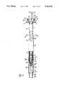
- FIG. 2is a longitudinal sectional view of the syringe according to FIG. 1, with the protective sleeve lying in its retracted position.
- FIG. 3shows the syringe according to FIG. 2 viewed in the direction of arrow III in this latter Figure, and with some parts in section.
- FIG. 4is a same view of the syringe as in FIG. 3, however with the protective sleeve lying in its advanced safety position.
- FIG. 5is a longitudinal sectional view of the syringe with the protective sleeve having been separated from the syringe along with the needle-carrying member and the needle, as a result of an attempt to re-use the syringe.
- FIG. 6is a perspective view showing the manner of holding the syringe of FIGS. 1 to 5 at the time of an injection.
- FIG. 7is a longitudinal sectional view in an enlarged scale showing a detail of the syringe according to FIG. 4.
- FIG. 8is an exploded perspective view showing a second embodiment of the syringe according to the invention.
- FIG. 9is a longitudinal sectional view in an enlarged scale showing the rear end of the syringe according to FIG. 8 with the protective sleeve lying in its retracted rest position.
- FIG. 10is a longitudinal sectional view in the same scale as in FIG. 9 showing the fore end of the protective sleeve of the syringe according to FIG. 8.
- FIG. 11is a view with parts in section showing the rear end of the syringe according to a third embodiment of the invention, with the protective sleeve lying in its advanced safety position.
- FIGS. 12 and 13are elevational part-sectional views showing the rear end of the syringe according to FIG. 11, with the protective sleeve in its retracted rest position in FIG. 12 and at the time when the sleeve is being released from the syringe barrel in FIG. 13.
- FIG. 14is a cross-sectional view taken on line XIV--XIV in FIG. 12.
- FIGS. 15 and 16are perspective views showing two details of the syringe according to FIGS. 11 to 14.
- syringe fore endis meant to refer to the end of the syringe that is fitted with the injection needle and the rear end of the syringe is the end thereof lying opposite to the needle. Also, all of the syringe members, but for the needle, are preferably made from a suitable plastics material or the like, unless it is differently specified.
- the disposable safety syringecomprises a barrel 1 with a conical forward end 2 on which the needle-carrying member 3 is fitted.
- the needle-carrying member 3is held on forward end 2 by friction by means of a matching conical hole formed at the rear end thereof, the rear end of needle 4 being firmly incorporated in the hole.
- the needle 4is normally protected by a needle-covering cap 5 removably fitted on the fore end of the needle-carrying member 3 so as to be caused to abut against an undercut 103 provided therein.
- a plunger 6is axially slidable in a fluid-tight manner and the head 8 of a manually driven stem 7 is engaged in the plunger 6.
- the rear end section of stem 7extends backwardly out of barrel 1 and is provided with a knob 9 on the rear end thereof.
- the stem 7has in cross section a non-circular shape, and is for example, T-like or X-like shaped.
- the rear end portion of barrel 1is so enlarged that a substantially cylindrical boxlike head 10 is formed which is provided with two diametrically opposite tabs 11 radially extending from its periphery.
- a protective sleeve 12is fitted on the outside of barrel 1 so as to be longitudinally slidably thereon.
- the rear end of the protective sleeve 12is formed with two diametrically opposite tabs 13 which extend radially from the periphery thereof and are like the tabs 11 of barrel 1.
- a helical spiral spring 15 of metalis interposed between an inward step 14, provided in the protective sleeve 12 at a distance from its rear end, and the boxlike head 10 of barrel 1.
- the protective sleeve 12is provided at its rear end with two clamping tongues 16 which are made of one piece therewith and which are formed therein at two diametrically opposite locations.
- Each clamping tongue 16extends lengthwise of the protective sleeve 12 at a longitudinal aperture 47 made therein.
- the forward end of the clamping tongue 16, i.e., the end thereof which is turned toward the needle 4,is integral with the protective sleeve 12.
- the rear end of clamping tongue 16extends beyond the rear end of the protective sleeve 12 and protrudes from the rear end thereof.
- Each clamping tongue 16can be elastically flexed outwardly in the radial direction, and at its rear end is formed with a hook-like clamping tooth 17 which is turned radially inwardly.
- Each clamping tongue 16is further provided at the rear end of its clamping tooth 17 with a slanted abutment face 18 which is downwardly inwardly inclined. Abutment faces 18 cooperate with the correspondingly inclined peripheral edge of a disc-shaped pusher member 19 secured to the stem 7 of plunger 6 close to the rear side of the boxlike head 10 of barrel 1, which pusher member 19 is opposite to and designed to go inbetween the clamping tongues 16.
- the boxlike head 10 at the rear end of barrel 1is formed close to each clamping tongue 16 with an aperture 20 extending into the bottom and into the sidewall of the boxlike head 10.
- each clamping tongue 16is allowed to penetrate into the boxlike head 10 and to be engaged by its hook-like clamping tooth 17 with the bottom of the head 10.
- two diametrically opposite slip-back preventing teeth 21are formed which are angularly offset by 90° from the two apertures 20 for the clamping tongues 16.
- the slip-back preventing teeth 21can be caused to elastically diverge radially outwardly from each other, and have their facing inward sides formed with slanted abutment faces 22 which are downwardly inwardly inclined.
- the slanted abutment faces 22cooperate with the correspondingly inclined peripheral edge of the disc-shaped pusher member 19.
- each locking tongue 23extends in the longitudinal direction of the protective sleeve 12.
- the forward end of each locking tongue 23is integral with the protective sleeve 12, and the rear end thereof is loose and tends to elastically flex radially inwardly.
- the rear free ends of the locking tongues 23cooperate with a peripheral outward undercut 203 in the needle-carrying member 3.
- the protective sleeve 12is formed in the direction of the syringe rear end, at a distance from the locking tongues 23, with a locking inward projection 25.
- Locking inward projection 25may be made in the form of an annular undercut or may consist of the fore ends of a plurality of ribs (not shown) provided at the interior of the protective sleeve 12.
- the locking inward projection 25 in the protective sleeve 12cooperates with the annular edge portion 303 of the rear end rim of the needle-carrying member 3.
- a tubular member 26is engaged in the fore end of the protective sleeve 12 and is fastened thereto such as by gluing or by welding.
- the rear end rim of the tubular member 26forms a retaining inward annular projection 27 in the protective sleeve 12.
- Front hole 28 in tubular member 26is tapered relative to the inside diameter of the protective sleeve 12, and is only slightly greater than the outside diameter of the rear end portion of the needle-covering cap 5.
- the syringeis sold to a user in the condition shown in FIGS. 2 and 3, with the plunger 6 slightly drawn back from its forwardmost position and with the syringe entirely emptied.
- the disc-shaped pusher member 19is a little outside of the boxlike head 10 at the rear end of barrel 1 and is prevented from getting into the head by a tearable safety strip 29 of paper, paperboard, or the like.
- the strip 29is threaded on the stem 7 of plunger 6 and is positioned between the disc-shaped pusher member 19 and the rim of the opening at the rear side of the boxlike head 10.
- the protective sleeve 12lies in its retracted rest position in which the clamping tongues 16 are caused to penetrate through the apertures 20 into the boxlike head 10 of barrel 1.
- the hook-like clamping teeth 17 of the clamping tongues 16are engaged with the bottom of the head 10 whereby the protective sleeve 12 is fastened to the barrel 1.
- the spring 15is loaded (compressed) and the tabs 13 radially extending from the periphery of the protective sleeve 12 are caused to bear, or almost bear, against the forward face of the corresponding tabs 11 provided on the boxlike head 10 of barrel 1.
- the tapered fore part 26 thereofextends substantially to the forward end of the needle-carrying member 3 so that the needle 4 is set free in an exposed condition at the time when the needle-covering cap 5 will be forwardly disengaged.
- the protective sleeve 12is caused to bear, or almost bear, by its inward annular projection 27 formed by the rear end rim of the tubular member 26 backwardly against the outward annular undercut 203 in the needle-carrying member 3.
- the plunger 6can be freely retracted by drawing back its stem 7 so that the syringe barrel 1 will be filled as usual by sucking the to-be-injected liquid through the exposed needle 4.
- the safety strip 29has to be torn away, and the syringe has to be held as shown in FIG. 6.
- the syringeis held with two fingers of a user's hand resting each on the front side of the respective tab 13 radially extending from the periphery of the protective sleeve 12 rear end, and with the user's thumb placed on the knob 9 of the plunger stem 7 pressing forward the plunger 6.
- the disc-shaped pusher member 19is caused to penetrate into the barrel 1 boxlike head 10 from the opening at the rear end thereof and by its peripheral edge is caused to act on the slanted abutment faces 18 of the clamping tongues 16.
- clamping tongues 16are caused to elastically diverge outwardly from each other so that their hook-like clamping teeth 17 become disengaged from the bottom of the boxlike head 10 of barrel 1.
- the protective sleeve 12is thus unfastened from barrel 1, but is still retained in its retracted rest position against the load of the pressure spring 15 by the user's hand, as disclosed by referring to FIG. 6.
- the disc-shaped pusher member 19is also caused to act by its peripheral edge also upon the slanted abutment faces 22 of the slip-back preventing teeth 21 and to pass thereover.
- the teeth 21are thus elastically opened out, so that they are caused to snappingly engage the top side of the disc-shaped pusher member 19. Therefore, on injecting, the pusher member 19 is locked in the boxlike head 10 of barrel 1 at the end or almost at the end of the forward stroke of plunger 6 between the bottom of the head 10 and the slip-back preventing teeth 21. In such a position, the clamping tongues 16 are kept in their opened out condition and the protective sleeve 12 is thus disengaged from the barrel 1, as shown in the upper part of FIG. 4.
- peripheral radial tabs 13 extending from the rear end of the protective sleeve 12are released by the user so that the protective sleeve which is now disengaged from the barrel 1 is moved forward by the spring 15, either gradually or snappingly into its advanced safety position shown in FIG. 4.
- the protective sleeve lying in its advanced safety positionextends around the needle 4 so as to entirely cover the same.
- the protective sleeve 12is at the same time caused to abut by its locking inward projection 25 backward against the annular step 303 formed by the edge portion of the rear end rim of the needle-carrying member 3, and the rear free ends of the locking tongues 23 are simultaneously caused to bear backward against the outward annular undercut 203 in the needle-carrying member 3, as more particularly shown in FIG. 7.
- the protective sleeve lying in its advanced safety positionis unremovably locked to the barrel in both senses of its longitudinal direction, i.e., either forward and backward, by means of the needle-carrying member 3.
- the needle-carrying member 3would be, at the most, disengaged from the conical forward end of barrel 1.
- the protective sleeve 12would be detached from barrel 1 together with the needle-carrying member 3 that is inseparably shut in the protective sleeve 12, and so together with the needle 4 enclosed in the protective sleeve 12, as shown in FIG. 5.
- the protective sleeve 12can be made with no problem and at a low cost from such a tough and strong plastics material that the protective sleeve could not be broken without damaging and rendering the needle-carrying member 3 and also the needle 4 unusable.
- the fore part 26 of the protective sleeve 12has such a narrow hole 28 and extends over such a long section beyond the pointed end of needle 4 that the finger of a person is prevented from reaching to the needle 4 from the fore end of the syringe.
- the stem 7 of plunger 6may be provided with an easily breakable weakened portion 32 at a point between the disc shaped pusher member 19 and the knob 9 on the rear end of stem 7, preferably at a point being adjacent to the disc-shaped pusher member 19. Owing to the provision of this weakened portion, the rear end section of stem 7 will be broken when an attempt is made to pull back the plunger 6 for trying to re-use the syringe once the disc-shaped pusher member 19 has been locked in the boxlike head 10 of barred 1 by the slip-back preventing teeth 21.
- the protective sleeve 12can be slidably but non-rotatably fitted on the barrel 1 with the aid of simple means known to those skilled in the art, such as by an inward projection in sleeve 12 slidably engaged in a longitudinal groove in the outward side of barrel 1, or vice-versa.
- the boxlike head 10 at the rear end of barrel 1has a sidewall 33.
- the sidewall 33radially covers from the outside the rear free ends forming the hook-like clamping teeth 17 of the clamping tongues 16, which enter into the boxlike head 10 through the apertures 20' in the bottom thereof.
- the removable safety means for initially preventing the disc-shaped pusher member 19 from getting into the boxlike head 10 at the rear end of barrel 1consist of a substantially part-circular small cover member 34 formed with a central opening 36 for allowing the stem 7 to pass therethrough.
- the cover member 34is provided in place of the tearable strip 29 of paper or paperboard.
- the small cover member 34is applied to the opening at the rear side of the boxlike head 10 and, for this purpose, is formed at its front side which is turned toward the syringe fore end with two diametrically opposite wedge-shaped teeth 35.
- the teeth 35extend from the cover member 34 and are introduced into the opening at the rear side of the boxlike head 10 so as to be inserted respectively between the two clamping tongues 16 and the sidewall 33.
- clamping tongues 16are engaged with the bottom of the boxlike head 10 and the respective portion of the sidewall 33 thereof, as shown in FIG. 9.
- the two teeth 35will hold the cover member 34 in position on the boxlike head 10 at the rear end of barrel 1, and at the same time will prevent the rear free ends of the clamping tongues 16 from being radially outwardly flexed and then from being disengaged from the boxlike head 10.
- the thus applied cover member 34partly closes the opening of the boxlike head 10 at the rear end of barrel 1, and therefore prevents the disc-shaped pusher member 19 from entering into the head 10.
- the cover member 34Before the syringe is used for an injection, the cover member 34 must be removed. Therefore, a syringe user has to grip the cover member 34 with two fingers of his hand close to the preferably indented peripheral edge thereof at two diametrically opposite positions. Then, the user axially disengages the cover member 34 from the boxlike head 10 at the rear end of barrel 1, and finally slips the same radially off the stem 7 of plunger 6.
- the tubular member 26' forming the fore part of the protective sleeve 12has a tapered front hole 28 which is only a little wider than the rear end portion of the needle-covering cap 5.
- the tubular member 26'is threaded on the outside of the protective sleeve 12 and is snappingly engaged therewith in an unremovable manner. Therefore, the protective sleeve 12 is provided with a front end section of a reduced diameter in which the locking tongues 23 are formed, and on which the tubular member 26' is fitted so as to be caused to abut against an outward annular undercut 39 formed in the protective sleeve 12.
- the tubular member 26'is locked in this position by two outward detents 37 which are provided in diametrically opposite positions on the outside of the protective sleeve 12 and which are snappingly engaged into respective peripheral slots 38 in the tubular member 26'.
- the tubular member 26'With the tubular member 26' being in its engaged position, the tubular member is caused to abut by an inward annular step 27' thereof against the fore end rim of the protective sleeve 12, as more particularly shown in FIG. 10.
- the width of the internal annular step 27'is such that this step partly extends also into the protective sleeve 12, so that its radially inwardly edge portion forms the retaining annular projection which is for cooperating with the outward annular undercut 203 in the needle-carrying member 3.
- FIGS. 11 to 16showing a further modified embodiment of the syringe according to the invention, the already described parts are also designated by the same reference numerals.
- a platelet 40which is shown in upturned position in FIG. 16 is arranged on the bottom of the boxlike head 10 of barrel 1.
- the platelet 40is engaged in the respective apertures 42 formed in the bottom of the head 10.
- the platelet 40is thus non-rotatably retained in the boxlike head 10 of barrel 1, and is caused to non-rotatably guide the stem 7 of plunger 6.
- the stem 7is T-shaped in cross section, and by the leg of its T-shaped cross section is passed through a relative narrow opening 43 in platelet 40.
- two pairs of diametrically opposite clamping tongues 16'are provided in the syringe according to the modified embodiment shown in FIGS. 11 to 16 at respective longitudinal apertures 47 in the protective sleeve 12.
- the two clamping tongues 16' of each pairare arranged in facing relation along an arc and in a substantially tangential plane with their hook-like clamping teeth 17' being turned outwardly in opposite directions and with their slanted abutment faces 18' being downwardly outwardly inclined.
- Each pair of clamping tongues 16'is caused to get into the boxlike head 10 at the rear end of barrel 1 through an aperture 20' in the bottom of the head 10 and through a relative peripheral aperture 44 formed in platelet 40.
- the hook-like clamping teeth 17' of the clamping tongues 16'are each engaged with the edges of the relative peripheral aperture 44 in platelet 40.
- the disc-shaped pusher member 19' secured to the stem 7 of plunger 6is formed with an opening consisting of a peripheral recess 45.
- the disc-shaped pusher member 19'becomes locked between the platelet 40 and the slip-back preventing teeth 21 provided in the boxlike head 10, as more particularly shown in FIG. 11.
- the diametrically opposite tabs 11 radially extending from the periphery of the boxlike head 10are preferably fitted with pins 46 which are engaged in respective holes in tabs 13 radially extending from the periphery of the protective sleeve 12.
Landscapes
- Health & Medical Sciences (AREA)
- Engineering & Computer Science (AREA)
- General Health & Medical Sciences (AREA)
- Public Health (AREA)
- Anesthesiology (AREA)
- Biomedical Technology (AREA)
- Heart & Thoracic Surgery (AREA)
- Hematology (AREA)
- Life Sciences & Earth Sciences (AREA)
- Animal Behavior & Ethology (AREA)
- Environmental & Geological Engineering (AREA)
- Vascular Medicine (AREA)
- Veterinary Medicine (AREA)
- Infusion, Injection, And Reservoir Apparatuses (AREA)
- Portable Nailing Machines And Staplers (AREA)
- Burglar Alarm Systems (AREA)
- Organic Low-Molecular-Weight Compounds And Preparation Thereof (AREA)
- Ultra Sonic Daignosis Equipment (AREA)
- External Artificial Organs (AREA)
- Medicines Containing Material From Animals Or Micro-Organisms (AREA)
Abstract
Description
Claims (20)
Applications Claiming Priority (4)
| Application Number | Priority Date | Filing Date | Title |
|---|---|---|---|
| IT02097990AIT1243354B (en) | 1990-07-19 | 1990-07-19 | Disposable syringe |
| IT20979A/90 | 1990-07-19 | ||
| ITGE91A000008 | 1990-10-09 | ||
| IT91GE8IT1248101B (en) | 1991-01-09 | 1991-01-09 | Disposable safety syringe with slidable protective sleeve - initially held by releasable clamp and lockable extended after use |
Publications (1)
| Publication Number | Publication Date |
|---|---|
| US5163918Atrue US5163918A (en) | 1992-11-17 |
Family
ID=26327722
Family Applications (1)
| Application Number | Title | Priority Date | Filing Date |
|---|---|---|---|
| US07/727,970Expired - LifetimeUS5163918A (en) | 1990-07-19 | 1991-07-10 | Disposable safety syringe |
Country Status (17)
| Country | Link |
|---|---|
| US (1) | US5163918A (en) |
| EP (1) | EP0467173B1 (en) |
| JP (1) | JPH0810324A (en) |
| AT (1) | ATE129906T1 (en) |
| AU (1) | AU622367B1 (en) |
| BR (1) | BR9103082A (en) |
| CA (1) | CA2047263C (en) |
| DE (1) | DE69114390T2 (en) |
| DK (1) | DK0467173T3 (en) |
| ES (1) | ES2082052T3 (en) |
| FI (1) | FI913313A7 (en) |
| GR (1) | GR3018753T3 (en) |
| IL (1) | IL98759A (en) |
| MX (1) | MX9100265A (en) |
| NO (1) | NO912812L (en) |
| PT (1) | PT98378B (en) |
| RU (1) | RU2079308C1 (en) |
Cited By (93)
| Publication number | Priority date | Publication date | Assignee | Title |
|---|---|---|---|---|
| US5201720A (en)* | 1992-04-21 | 1993-04-13 | Joseph Borgia | Syringe holding and ejecting assembly |
| US5395339A (en)* | 1992-01-31 | 1995-03-07 | Sherwood Medical Company | Medical device with sterile fluid pathway |
| US5562624A (en)* | 1994-05-06 | 1996-10-08 | Righi; Nardino | Non-reusable safety syringe |
| US5573510A (en)* | 1994-02-28 | 1996-11-12 | Isaacson; Dennis R. | Safety intravenous catheter assembly with automatically retractable needle |
| USD377687S (en)* | 1995-10-19 | 1997-01-28 | Dallas Udovch | Single-use syringe |
| US5637092A (en)* | 1995-01-30 | 1997-06-10 | Shaw; Thomas J. | Syringe plunger locking assembly |
| US6090077A (en)* | 1995-05-11 | 2000-07-18 | Shaw; Thomas J. | Syringe plunger assembly and barrel |
| US6319233B1 (en) | 1998-04-17 | 2001-11-20 | Becton, Dickinson And Company | Safety shield system for prefilled syringes |
| US6319234B1 (en)* | 1997-02-12 | 2001-11-20 | Sergio Restelli | Disposable safety syringe |
| US6419658B1 (en)* | 1998-01-20 | 2002-07-16 | Sergio Restelli | Disposable safety syringe |
| US20020193746A1 (en)* | 1999-12-07 | 2002-12-19 | Stephane Chevallier | Safety system for a syringe |
| US6530903B2 (en) | 2000-02-24 | 2003-03-11 | Xiping Wang | Safety syringe |
| US6572584B1 (en) | 2000-08-07 | 2003-06-03 | Retractable Technologies, Inc. | Retractable syringe with reduced retraction force |
| US6638256B2 (en) | 1997-09-30 | 2003-10-28 | Becton Dickinson France S.A. | Lockable safety shield assembly for a prefillable syringe |
| USD483861S1 (en) | 2001-08-01 | 2003-12-16 | Astrazeneca Ab | Injection device with pull off strip |
| US6679864B2 (en) | 1998-04-17 | 2004-01-20 | Becton Dickinson And Company | Safety shield system for prefilled syringes |
| US6716191B2 (en)* | 2001-02-14 | 2004-04-06 | Rest Elli Sergio | Disposable syringe |
| US6719730B2 (en) | 1998-04-17 | 2004-04-13 | Becton, Dickinson And Company | Safety shield system for prefilled syringes |
| US20040092884A1 (en)* | 2002-04-25 | 2004-05-13 | Compagnie Plastic Omnium | Liquid-injection syringe assembly, and a sheath for the assembly |
| US20040147875A1 (en)* | 2001-03-14 | 2004-07-29 | Wallace Bruce Ingram | Non-reusable syringe |
| US20050080383A1 (en)* | 2003-02-27 | 2005-04-14 | Kevin Woehr | Safety syringes |
| US20050096596A1 (en)* | 2003-11-03 | 2005-05-05 | Becton, Dickinson And Company | Safety shield system for a syringe |
| US20050096599A1 (en)* | 2003-11-03 | 2005-05-05 | Becton, Dickinson & Company | Safety device for a syringe |
| US20050096598A1 (en)* | 2003-11-03 | 2005-05-05 | Becton, Dickinson And Company | Safety shield system for a syringe |
| US20050096597A1 (en)* | 2003-11-03 | 2005-05-05 | Becton, Dickinson And Company | Safety shield system for a syringe |
| US6913595B2 (en) | 2000-12-22 | 2005-07-05 | Nicodel S.A. | Medical device and locking mechanism therefor |
| US20050148943A1 (en)* | 2002-02-11 | 2005-07-07 | Stephane Chevalier | Safe support device for a syringe and an assembly comprising such a device and a syringe |
| US20050159706A1 (en)* | 2004-01-20 | 2005-07-21 | Becton, Dickinson And Company | Medical syringe with safety shield system |
| US20050159709A1 (en)* | 2004-01-20 | 2005-07-21 | Becton, Dickinson And Company | Safety shield system for a plastic syringe |
| US20050159705A1 (en)* | 2004-01-20 | 2005-07-21 | Becton, Dickinson And Company | Syringe having a retractable needle |
| US20050159707A1 (en)* | 2004-01-20 | 2005-07-21 | Becton, Dickinson And Company | Syringe having a retractable needle |
| US6966898B1 (en)* | 1999-10-26 | 2005-11-22 | Compagnie Plastic Omnium | Safety device for an injection syringe |
| US20060036216A1 (en)* | 2001-10-15 | 2006-02-16 | Compagnie Plastic Omnium | Safety device for a syringe |
| US7001364B1 (en)* | 2002-08-13 | 2006-02-21 | Parham Farhi | Needle safety cap device |
| US20060189933A1 (en)* | 2005-02-18 | 2006-08-24 | Becton, Dickinson And Company | Safety shield system for a syringe |
| US7118552B2 (en) | 2000-02-18 | 2006-10-10 | Astrazeneca Ab | Automatically operable safety shield system for syringes |
| US20070179441A1 (en)* | 2003-10-22 | 2007-08-02 | Stephane Chevallier | Protected injection syringe device |
| US20070253984A1 (en)* | 2006-04-26 | 2007-11-01 | Wyeth | Novel formulations which stabilize and inhibit precipitation of immunogenic compositions |
| US20070265576A1 (en)* | 2004-08-27 | 2007-11-15 | Olivier Pessin | Injection Device Comprising a Syringe |
| US20080021409A1 (en)* | 2003-03-25 | 2008-01-24 | Sedat | Device for protection of the needle for a syringe and injection device comprising a syringe and said protection device |
| US20080208125A1 (en)* | 2004-06-23 | 2008-08-28 | Owen Mumford Limited | Automatic Injection Devices |
| US20090204076A1 (en)* | 2003-02-03 | 2009-08-13 | Barry Peter Liversidge | Medical Injector |
| US20100076378A1 (en)* | 2007-03-21 | 2010-03-25 | Midland Medical Devices Holdings, Llc | Safety Medical Syringe with Retractable Needle and Including a Plunger that is Received within a Barrel |
| US20100217205A1 (en)* | 2007-10-23 | 2010-08-26 | Tech Group Europe Ltd. | Syringe device comprising a syringe body and a bearing sleeve |
| US7803132B2 (en) | 2004-10-14 | 2010-09-28 | Midland Medical Device Holdings, LLC | Safety medical syringe with retractable needle |
| US7846135B2 (en) | 2006-02-24 | 2010-12-07 | Midland Medical Holding LLC | Retractable needle syringe with needle trap |
| US7985216B2 (en) | 2004-03-16 | 2011-07-26 | Dali Medical Devices Ltd. | Medicinal container engagement and automatic needle device |
| US20110230832A1 (en)* | 2006-09-20 | 2011-09-22 | Becton Dickinson France S.A.S. | Injection Device Preventing the Return of the Piston When the Safety System Is Deployed |
| US8057431B2 (en) | 2006-12-21 | 2011-11-15 | B. Braun Melsungen Ag | Hinged cap for needle device |
| US8287491B2 (en) | 2008-11-26 | 2012-10-16 | Becton, Dickinson And Company | Single-use auto-disable syringe |
| US8376998B2 (en) | 2003-09-17 | 2013-02-19 | Elcam Medical Agricultural Cooperative Association Ltd. | Automatic injection device |
| US20130131598A1 (en)* | 2009-04-24 | 2013-05-23 | Corium International, Inc. | Methods for manufacturing microprojection arrays |
| CN103127589A (en)* | 2013-03-26 | 2013-06-05 | 魏颖德 | Safety self-destruction syringe |
| US20130144255A1 (en)* | 2011-12-06 | 2013-06-06 | Robert J. Cohn | Syringe assemblies including a safety shield for a needle |
| US8636704B2 (en) | 2009-04-29 | 2014-01-28 | Abbvie Biotechnology Ltd | Automatic injection device |
| US8679061B2 (en) | 2006-06-30 | 2014-03-25 | Abbvie Biotechnology Ltd | Automatic injection device |
| US8708968B2 (en) | 2011-01-24 | 2014-04-29 | Abbvie Biotechnology Ltd. | Removal of needle shields from syringes and automatic injection devices |
| US8758301B2 (en) | 2009-12-15 | 2014-06-24 | Abbvie Biotechnology Ltd | Firing button for automatic injection device |
| US9022990B2 (en) | 2011-04-04 | 2015-05-05 | Tech Group Europe Limited | Needle safety shield |
| US9050416B2 (en) | 2012-11-01 | 2015-06-09 | Tech Group Europe Limited | Needle Safety device with floating ring |
| US9095567B2 (en) | 2010-06-04 | 2015-08-04 | Wyeth Llc | Vaccine formulations |
| US9180244B2 (en) | 2010-04-21 | 2015-11-10 | Abbvie Biotechnology Ltd | Wearable automatic injection device for controlled delivery of therapeutic agents |
| US9265887B2 (en) | 2011-01-24 | 2016-02-23 | Abbvie Biotechnology Ltd. | Automatic injection devices having overmolded gripping surfaces |
| FR3025724A1 (en)* | 2014-09-17 | 2016-03-18 | Nemera La Verpilliere | SAFETY DEVICE FOR AN INJECTION SYRINGE COMPRISING IMPROVED WAFER OPENING RETENTION MEANS |
| US9452280B2 (en) | 2007-04-16 | 2016-09-27 | Corium International, Inc. | Solvent-cast microprotrusion arrays containing active ingredient |
| US9498524B2 (en) | 2007-04-16 | 2016-11-22 | Corium International, Inc. | Method of vaccine delivery via microneedle arrays |
| US9623193B2 (en)* | 2011-12-06 | 2017-04-18 | Robert J. Cohn | Syringe assembly with automatic safety shield |
| CN107773813A (en)* | 2016-08-31 | 2018-03-09 | 上海凯茂生物医药有限公司 | A kind of precharging preparation of the erythropoietin class parenteral solution with safety guard |
| US9943646B2 (en) | 2014-08-21 | 2018-04-17 | Owen Mumford Ltd. | Safety syringe |
| USD823463S1 (en) | 2012-12-14 | 2018-07-17 | Retractable Technologies, Inc. | Frontal attachment for medical device |
| GB2563029A (en)* | 2017-05-30 | 2018-12-05 | Janssen Pharmaceuticals Inc | Grip accessory for a manual injection device |
| US10195409B2 (en) | 2013-03-15 | 2019-02-05 | Corium International, Inc. | Multiple impact microprojection applicators and methods of use |
| US10245422B2 (en) | 2013-03-12 | 2019-04-02 | Corium International, Inc. | Microprojection applicators and methods of use |
| US10384046B2 (en) | 2013-03-15 | 2019-08-20 | Corium, Inc. | Microarray for delivery of therapeutic agent and methods of use |
| US10384045B2 (en) | 2013-03-15 | 2019-08-20 | Corium, Inc. | Microarray with polymer-free microstructures, methods of making, and methods of use |
| US10624843B2 (en) | 2014-09-04 | 2020-04-21 | Corium, Inc. | Microstructure array, methods of making, and methods of use |
| USD888941S1 (en) | 2017-11-30 | 2020-06-30 | Janssen Pharmacauticals, Inc. | Grip accessory for a manual injection device |
| US10806867B2 (en) | 2011-01-24 | 2020-10-20 | E3D Agricultural Cooperative Association Ltd. | Injector |
| US10857093B2 (en) | 2015-06-29 | 2020-12-08 | Corium, Inc. | Microarray for delivery of therapeutic agent, methods of use, and methods of making |
| US10912715B2 (en) | 2015-11-30 | 2021-02-09 | Biocorp Production | Device for connecting a vessel and a container and connection assembly including such a device |
| US11052231B2 (en) | 2012-12-21 | 2021-07-06 | Corium, Inc. | Microarray for delivery of therapeutic agent and methods of use |
| US11123499B2 (en)* | 2016-01-19 | 2021-09-21 | Merck Sharp & Dohme Corp. | Prefilled disposable injection device |
| USD946750S1 (en) | 2018-07-11 | 2022-03-22 | Janssen Pharmaceuticals, Inc. | Grip accessory for an injection device |
| US11338096B2 (en)* | 2014-11-21 | 2022-05-24 | Shl Medical Ag | Medicament injection device |
| US11400223B2 (en) | 2011-12-08 | 2022-08-02 | Sanofi-Aventis Deutschland Gmbh | Syringe carrier |
| US11419816B2 (en) | 2010-05-04 | 2022-08-23 | Corium, Inc. | Method and device for transdermal delivery of parathyroid hormone using a microprojection array |
| CN115317725A (en)* | 2022-07-29 | 2022-11-11 | 苏州嘉树医疗科技有限公司 | A needle stick prevention device |
| KR102514886B1 (en)* | 2022-09-19 | 2023-03-29 | (주)풍림파마텍 | Injection device to prevent reuse |
| CN117281979A (en)* | 2023-07-28 | 2023-12-26 | 梵颖(上海)生物科技有限公司 | Syringe protection device and safety syringe |
| US11890459B2 (en) | 2020-03-27 | 2024-02-06 | Medivena Sp. Z O.O. | Needle-based device with external safety cap and a needle guide element thereof |
| US11918791B2 (en) | 2017-05-30 | 2024-03-05 | Janssen Pharmaceuticals, Inc. | Grip accessory for a manual injection device |
| US12036392B1 (en) | 2013-03-14 | 2024-07-16 | Sanofi-Aventis Deutschland Gmbh | Medicament container carrier and adapter |
| US12318597B2 (en) | 2015-06-03 | 2025-06-03 | Sanofi-Aventis Deutschland Gmbh | Syringe carrier for an autoinjector and method of assembling |
Families Citing this family (26)
| Publication number | Priority date | Publication date | Assignee | Title |
|---|---|---|---|---|
| US5376080A (en)* | 1991-01-30 | 1994-12-27 | Petrussa; Gian L. | Single use retractable needle syringe |
| IT1248125B (en)* | 1991-01-30 | 1995-01-05 | Gian Luigi Petrussa | CONCEALED NEEDLE DEVICE |
| IT1253104B (en)* | 1991-07-02 | 1995-07-10 | Paolo Romagnoli | DISPOSABLE SYRINGE |
| US5445620A (en)* | 1993-09-17 | 1995-08-29 | Habley Medical Technology Corp. | Disposable safety syringe with retractable shuttle for Wyeth medication cartridge |
| US5514107A (en)* | 1994-02-10 | 1996-05-07 | Habley Medical Technology Corporation | Safety syringe adapter for cartridge-needle unit |
| FR2736553B1 (en)* | 1995-07-12 | 1998-01-09 | Soc Et Et D Applic Tech Sedat | INJECTION SYRINGE, IN PARTICULAR LIQUID MEDICAL PRODUCTS, WITH MOBILE NEEDLE PROTECTOR |
| FR2778853B1 (en) | 1998-05-19 | 2000-12-22 | Sedat | INJECTION SYRINGE WITH SPRING LOADED NEEDLE PROTECTOR |
| AUPQ664800A0 (en)* | 2000-04-04 | 2000-05-04 | Dyer, John Raymond | A retractable syringe system |
| EP1362609A1 (en)* | 2002-05-16 | 2003-11-19 | Sergio Restelli | Disposable safety syringe with automatically guided outer sleeve |
| ATE397948T1 (en)* | 2002-11-06 | 2008-07-15 | Becton Dickinson Co | PASSIVE NEEDLE PROTECTION DEVICE FOR INJECTION DEVICES |
| DE602004003549T2 (en) | 2003-02-11 | 2007-09-27 | Salvus Technology Ltd., Stradbroke | SAFETY PIN |
| FR2861598B1 (en)* | 2003-10-29 | 2006-06-16 | Plastef Investissements | SECURE INJECTION DEVICE FOR A SYRINGE |
| ATE542559T1 (en)* | 2003-11-27 | 2012-02-15 | Salvus Technology Ltd | SAFETY SYRINGE |
| GB0500366D0 (en)* | 2005-01-08 | 2005-02-16 | Liversidge Barry P | Medical needle safety devices |
| US8827961B2 (en) | 2005-02-03 | 2014-09-09 | West Pharmaceutical Services, Inc. | Safety needle |
| US8597255B2 (en) | 2005-02-03 | 2013-12-03 | Salvus Technology Limited | Safety needle |
| US8235950B2 (en) | 2005-02-03 | 2012-08-07 | Salvus Technology GmbH | Safety needle |
| AU2006217781B2 (en) | 2005-02-25 | 2010-09-16 | Salvus Technology Limited | Safety needle accessory |
| US8372044B2 (en)* | 2005-05-20 | 2013-02-12 | Safety Syringes, Inc. | Syringe with needle guard injection device |
| EP2029202B1 (en)* | 2006-06-16 | 2013-12-25 | Marc Brunel | Safety device for injecting a medicinal product, such as a lyophilized product |
| JP4566223B2 (en)* | 2007-08-02 | 2010-10-20 | 株式会社アルテ | Container / Syringe |
| US8105292B2 (en) | 2008-02-11 | 2012-01-31 | Safety Syringes, Inc. | Reconstitution means for safety device |
| WO2013037744A1 (en) | 2011-09-13 | 2013-03-21 | Sanofi-Aventis Deutschland Gmbh | Injection device |
| EP2601990A1 (en)* | 2011-12-08 | 2013-06-12 | Sanofi-Aventis Deutschland GmbH | Syringe carrier |
| USD765838S1 (en) | 2015-03-26 | 2016-09-06 | Tech Group Europe Limited | Syringe retention clip |
| WO2016158145A1 (en)* | 2015-03-30 | 2016-10-06 | テルモ株式会社 | Injection needle assembly, and drug injection device |
Citations (16)
| Publication number | Priority date | Publication date | Assignee | Title |
|---|---|---|---|---|
| DE273201C (en)* | ||||
| US4639249A (en)* | 1986-01-13 | 1987-01-27 | Larson Eldon E | Latch integral with latched apparatus |
| US4787891A (en)* | 1987-07-13 | 1988-11-29 | Paul Levin | Syringe holder and applicator |
| US4911693A (en)* | 1988-10-17 | 1990-03-27 | Paris Frassetti R | Hypodermic syringe needle guard |
| US4927416A (en)* | 1987-12-02 | 1990-05-22 | National Medical Device Corporation | User-protective hypodermic syringe holder |
| US4932947A (en)* | 1989-02-17 | 1990-06-12 | Cardwell Dieter W | Syringe apparatus |
| US4957490A (en)* | 1986-12-16 | 1990-09-18 | National Research Development Corporation | Injection device |
| US5013302A (en)* | 1989-12-26 | 1991-05-07 | Schmidt Industries, Inc. | Hypodermic needle sheath |
| US5013301A (en)* | 1988-11-18 | 1991-05-07 | Marotta Jr Phillip | Syringe holder |
| US5061251A (en)* | 1990-06-12 | 1991-10-29 | Juhasz Paul R | Syringe device |
| US5106379A (en)* | 1991-04-09 | 1992-04-21 | Leap E Jack | Syringe shielding assembly |
| US5114404A (en)* | 1990-07-24 | 1992-05-19 | Paxton Gerald R | Multifunctional retractable needle type general purpose disabling syringe having enhanced safety features and related method of operation |
| US5116326A (en)* | 1991-04-25 | 1992-05-26 | Schmidt Industries, Inc. | Hypodermic needle sheath |
| US5120310A (en)* | 1991-04-03 | 1992-06-09 | Shaw Thomas J | Nonreusable syringe |
| US5120311A (en)* | 1989-11-01 | 1992-06-09 | Medical Safety Products, Inc. | Blood collection tube holder |
| US5120309A (en)* | 1989-06-09 | 1992-06-09 | Watts Kenneth A | Hypodermic syringe with protective shield |
Family Cites Families (8)
| Publication number | Priority date | Publication date | Assignee | Title |
|---|---|---|---|---|
| US3478937A (en)* | 1968-01-22 | 1969-11-18 | Ida Solowey | Disposable single unit-dose syringe with locking plunger |
| GB2197792A (en)* | 1986-11-26 | 1988-06-02 | Power Richard Kiteley | Disposable syringes |
| US4850968A (en)* | 1987-07-27 | 1989-07-25 | Ar.Ma.S.R.L. | Self-blocking hypodermic syringe for once-only use, comprising a needle protection cap |
| US4927018A (en)* | 1988-12-06 | 1990-05-22 | Herbert Yang | Disposable covered needle safety assembly |
| US4935015A (en)* | 1988-12-14 | 1990-06-19 | Hall John E | Syringe apparatus with retractable needle |
| FR2648716B1 (en)* | 1989-06-27 | 1991-09-13 | Guerineau Jean | SINGLE USE SYRINGE. SELF-CONTAINING SYRINGE-NEEDLE COMBINATION IN A PROTECTIVE SLEEVE |
| FR2650187B2 (en)* | 1989-06-27 | 1992-01-17 | Guerineau Jean | SELF-RETRACTING NEEDLE-SYRINGE COMBINATION |
| AU5889490A (en)* | 1989-07-11 | 1991-01-17 | Karl Peter Schulze | Syringes |
- 1991
- 1991-07-05DKDK91111239.9Tpatent/DK0467173T3/enactive
- 1991-07-05ESES91111239Tpatent/ES2082052T3/ennot_activeExpired - Lifetime
- 1991-07-05DEDE69114390Tpatent/DE69114390T2/ennot_activeExpired - Fee Related
- 1991-07-05EPEP91111239Apatent/EP0467173B1/ennot_activeExpired - Lifetime
- 1991-07-05ATAT91111239Tpatent/ATE129906T1/ennot_activeIP Right Cessation
- 1991-07-08ILIL9875991Apatent/IL98759A/ennot_activeIP Right Cessation
- 1991-07-09FIFI913313Apatent/FI913313A7/enunknown
- 1991-07-10USUS07/727,970patent/US5163918A/ennot_activeExpired - Lifetime
- 1991-07-16AUAU80494/91Apatent/AU622367B1/ennot_activeCeased
- 1991-07-17CACA002047263Apatent/CA2047263C/ennot_activeExpired - Fee Related
- 1991-07-18NONO91912812Apatent/NO912812L/enunknown
- 1991-07-18PTPT98378Apatent/PT98378B/ennot_activeIP Right Cessation
- 1991-07-18BRBR919103082Apatent/BR9103082A/ennot_activeIP Right Cessation
- 1991-07-18RUSU915001258Apatent/RU2079308C1/ennot_activeIP Right Cessation
- 1991-07-18MXMX9100265Apatent/MX9100265A/ennot_activeIP Right Cessation
- 1991-07-19JPJP3203541Apatent/JPH0810324A/enactivePending
- 1996
- 1996-01-23GRGR960400151Tpatent/GR3018753T3/enunknown
Patent Citations (16)
| Publication number | Priority date | Publication date | Assignee | Title |
|---|---|---|---|---|
| DE273201C (en)* | ||||
| US4639249A (en)* | 1986-01-13 | 1987-01-27 | Larson Eldon E | Latch integral with latched apparatus |
| US4957490A (en)* | 1986-12-16 | 1990-09-18 | National Research Development Corporation | Injection device |
| US4787891A (en)* | 1987-07-13 | 1988-11-29 | Paul Levin | Syringe holder and applicator |
| US4927416A (en)* | 1987-12-02 | 1990-05-22 | National Medical Device Corporation | User-protective hypodermic syringe holder |
| US4911693A (en)* | 1988-10-17 | 1990-03-27 | Paris Frassetti R | Hypodermic syringe needle guard |
| US5013301A (en)* | 1988-11-18 | 1991-05-07 | Marotta Jr Phillip | Syringe holder |
| US4932947A (en)* | 1989-02-17 | 1990-06-12 | Cardwell Dieter W | Syringe apparatus |
| US5120309A (en)* | 1989-06-09 | 1992-06-09 | Watts Kenneth A | Hypodermic syringe with protective shield |
| US5120311A (en)* | 1989-11-01 | 1992-06-09 | Medical Safety Products, Inc. | Blood collection tube holder |
| US5013302A (en)* | 1989-12-26 | 1991-05-07 | Schmidt Industries, Inc. | Hypodermic needle sheath |
| US5061251A (en)* | 1990-06-12 | 1991-10-29 | Juhasz Paul R | Syringe device |
| US5114404A (en)* | 1990-07-24 | 1992-05-19 | Paxton Gerald R | Multifunctional retractable needle type general purpose disabling syringe having enhanced safety features and related method of operation |
| US5120310A (en)* | 1991-04-03 | 1992-06-09 | Shaw Thomas J | Nonreusable syringe |
| US5106379A (en)* | 1991-04-09 | 1992-04-21 | Leap E Jack | Syringe shielding assembly |
| US5116326A (en)* | 1991-04-25 | 1992-05-26 | Schmidt Industries, Inc. | Hypodermic needle sheath |
Cited By (188)
| Publication number | Priority date | Publication date | Assignee | Title |
|---|---|---|---|---|
| US5395339A (en)* | 1992-01-31 | 1995-03-07 | Sherwood Medical Company | Medical device with sterile fluid pathway |
| US5201720A (en)* | 1992-04-21 | 1993-04-13 | Joseph Borgia | Syringe holding and ejecting assembly |
| US5573510A (en)* | 1994-02-28 | 1996-11-12 | Isaacson; Dennis R. | Safety intravenous catheter assembly with automatically retractable needle |
| US6056726A (en)* | 1994-02-28 | 2000-05-02 | Isaacson; Dennis Ray | Self-contained safety intravenous catheter insertion device |
| US5562624A (en)* | 1994-05-06 | 1996-10-08 | Righi; Nardino | Non-reusable safety syringe |
| US5637092A (en)* | 1995-01-30 | 1997-06-10 | Shaw; Thomas J. | Syringe plunger locking assembly |
| US6090077A (en)* | 1995-05-11 | 2000-07-18 | Shaw; Thomas J. | Syringe plunger assembly and barrel |
| US7351224B1 (en) | 1995-05-11 | 2008-04-01 | Shaw Thomas J | Retractable syringe assembly designed for one use |
| USD377687S (en)* | 1995-10-19 | 1997-01-28 | Dallas Udovch | Single-use syringe |
| US6319234B1 (en)* | 1997-02-12 | 2001-11-20 | Sergio Restelli | Disposable safety syringe |
| US6638256B2 (en) | 1997-09-30 | 2003-10-28 | Becton Dickinson France S.A. | Lockable safety shield assembly for a prefillable syringe |
| US6419658B1 (en)* | 1998-01-20 | 2002-07-16 | Sergio Restelli | Disposable safety syringe |
| US6319233B1 (en) | 1998-04-17 | 2001-11-20 | Becton, Dickinson And Company | Safety shield system for prefilled syringes |
| US6626864B2 (en) | 1998-04-17 | 2003-09-30 | Becton Dickinson France, S.A. | Safety shield system for prefilled syringes |
| US6685676B2 (en) | 1998-04-17 | 2004-02-03 | Becton Dickinson And Company | Safety shield system for prefilled syringes |
| US6719730B2 (en) | 1998-04-17 | 2004-04-13 | Becton, Dickinson And Company | Safety shield system for prefilled syringes |
| US6679864B2 (en) | 1998-04-17 | 2004-01-20 | Becton Dickinson And Company | Safety shield system for prefilled syringes |
| US6966898B1 (en)* | 1999-10-26 | 2005-11-22 | Compagnie Plastic Omnium | Safety device for an injection syringe |
| US8235967B2 (en)* | 1999-12-07 | 2012-08-07 | Sanofi-Aventis | Safety assembly for a syringe |
| US20150182704A1 (en)* | 1999-12-07 | 2015-07-02 | Sanofi | Safety assembly for a syringe |
| US7963949B2 (en) | 1999-12-07 | 2011-06-21 | Sanofi-Aventis | Safety assembly for a syringe |
| US20110213334A1 (en)* | 1999-12-07 | 2011-09-01 | Sanofi-Aventis | Safety assembly for a syringe |
| US20110213313A1 (en)* | 1999-12-07 | 2011-09-01 | Sanofi-Aventis | Safety assembly for a syringe |
| US10071207B2 (en)* | 1999-12-07 | 2018-09-11 | Sanofi | Safety assembly for a syringe |
| US8231571B2 (en)* | 1999-12-07 | 2012-07-31 | Sanofi-Aventis | Safety assembly for a syringe |
| US8979794B2 (en) | 1999-12-07 | 2015-03-17 | Sanofi-Aventis | Safety assembly for a syringe |
| US20080312603A1 (en)* | 1999-12-07 | 2008-12-18 | Sanofi-Aventis | Safety assembly for a syringe |
| US8617105B2 (en) | 1999-12-07 | 2013-12-31 | Sanofi-Aventis | Safety assembly for a syringe |
| US7429256B2 (en)* | 1999-12-07 | 2008-09-30 | Sanofi-Aventis | Safety system for a syringe |
| US20020193746A1 (en)* | 1999-12-07 | 2002-12-19 | Stephane Chevallier | Safety system for a syringe |
| US7220247B2 (en) | 2000-02-18 | 2007-05-22 | Astrazeneca Ab | Automatically operable safety shield system for syringes |
| US7118552B2 (en) | 2000-02-18 | 2006-10-10 | Astrazeneca Ab | Automatically operable safety shield system for syringes |
| US7500964B2 (en) | 2000-02-18 | 2009-03-10 | Astrazeneca Ab | Automatically operable safety shield system for syringes |
| BG65506B1 (en)* | 2000-02-18 | 2008-10-31 | Astrazeneca Ab | Automatically operable safety shield systemfor syringes |
| CZ302410B6 (en)* | 2000-02-18 | 2011-05-04 | Astrazeneca Ab | Automatically operable safety shield system for use with a syringe |
| US6530903B2 (en) | 2000-02-24 | 2003-03-11 | Xiping Wang | Safety syringe |
| US6572584B1 (en) | 2000-08-07 | 2003-06-03 | Retractable Technologies, Inc. | Retractable syringe with reduced retraction force |
| US6913595B2 (en) | 2000-12-22 | 2005-07-05 | Nicodel S.A. | Medical device and locking mechanism therefor |
| US6716191B2 (en)* | 2001-02-14 | 2004-04-06 | Rest Elli Sergio | Disposable syringe |
| US20040147875A1 (en)* | 2001-03-14 | 2004-07-29 | Wallace Bruce Ingram | Non-reusable syringe |
| US6905478B2 (en) | 2001-03-14 | 2005-06-14 | Glenord Pty. Ltd. | Non-reusable syringe |
| USD483861S1 (en) | 2001-08-01 | 2003-12-16 | Astrazeneca Ab | Injection device with pull off strip |
| US20060036216A1 (en)* | 2001-10-15 | 2006-02-16 | Compagnie Plastic Omnium | Safety device for a syringe |
| US8337467B2 (en)* | 2001-10-15 | 2012-12-25 | Rexam Healthcare La Verpilliere | Safety device for a syringe |
| US8308696B2 (en)* | 2002-02-11 | 2012-11-13 | Sanofi-Aventis | Needle sheathing device with flexible end-piece for syringe |
| US11135377B2 (en)* | 2002-02-11 | 2021-10-05 | Sanofi | Needle sheathing device with flexible end-piece for syringe |
| US20170203048A1 (en)* | 2002-02-11 | 2017-07-20 | Sanofi | Needle Sheathing Device With Flexible End-Piece For Syringe |
| US8603043B2 (en) | 2002-02-11 | 2013-12-10 | Sanofi | Needle sheathing device with flexible end-piece for syringe |
| US7850661B2 (en)* | 2002-02-11 | 2010-12-14 | Sanofi-Aventis | Needle sheathing device with flexible end-piece for syringe |
| US20110046605A1 (en)* | 2002-02-11 | 2011-02-24 | Sanofi-Aventis | Needle sheathing device with flexible end-piece for syringe |
| US9555196B2 (en) | 2002-02-11 | 2017-01-31 | Sanofi | Needle sheathing device with flexible end-piece for syringe |
| US20080294120A1 (en)* | 2002-02-11 | 2008-11-27 | Sanofi-Aventis | Needle sheathing device with flexible end-piece for syringe |
| US20050148943A1 (en)* | 2002-02-11 | 2005-07-07 | Stephane Chevalier | Safe support device for a syringe and an assembly comprising such a device and a syringe |
| US7662131B2 (en)* | 2002-04-25 | 2010-02-16 | Compagnie Plastic Omnium | Liquid-injection syringe assembly, and a sheath for the assembly |
| US20040092884A1 (en)* | 2002-04-25 | 2004-05-13 | Compagnie Plastic Omnium | Liquid-injection syringe assembly, and a sheath for the assembly |
| US7001364B1 (en)* | 2002-08-13 | 2006-02-21 | Parham Farhi | Needle safety cap device |
| US20090204076A1 (en)* | 2003-02-03 | 2009-08-13 | Barry Peter Liversidge | Medical Injector |
| US20050080383A1 (en)* | 2003-02-27 | 2005-04-14 | Kevin Woehr | Safety syringes |
| US7544180B2 (en) | 2003-02-27 | 2009-06-09 | B. Braun Melsungen Ag | Safety syringes |
| US8845595B2 (en)* | 2003-03-25 | 2014-09-30 | Tech Group Europe Limited | Device for protection of the needle for a syringe and injection device comprising a syringe and said protection device |
| US20080021409A1 (en)* | 2003-03-25 | 2008-01-24 | Sedat | Device for protection of the needle for a syringe and injection device comprising a syringe and said protection device |
| EP2650033A2 (en) | 2003-09-17 | 2013-10-16 | Elcam Medical Agricultural Cooperative Association Ltd. | Automatic injection device |
| US11623051B2 (en) | 2003-09-17 | 2023-04-11 | E3D Agricultural Cooperative Association Ltd. | Automatic injection device |
| US8376998B2 (en) | 2003-09-17 | 2013-02-19 | Elcam Medical Agricultural Cooperative Association Ltd. | Automatic injection device |
| US9314575B2 (en)* | 2003-10-22 | 2016-04-19 | Tech Group Europe Limited | Protected injection syringe device |
| US20070179441A1 (en)* | 2003-10-22 | 2007-08-02 | Stephane Chevallier | Protected injection syringe device |
| US20050096596A1 (en)* | 2003-11-03 | 2005-05-05 | Becton, Dickinson And Company | Safety shield system for a syringe |
| US7497847B2 (en) | 2003-11-03 | 2009-03-03 | Becton, Dickinson And Company | Safety shield system for a syringe |
| US20050096599A1 (en)* | 2003-11-03 | 2005-05-05 | Becton, Dickinson & Company | Safety device for a syringe |
| US20050096598A1 (en)* | 2003-11-03 | 2005-05-05 | Becton, Dickinson And Company | Safety shield system for a syringe |
| US20050096597A1 (en)* | 2003-11-03 | 2005-05-05 | Becton, Dickinson And Company | Safety shield system for a syringe |
| US7101351B2 (en) | 2003-11-03 | 2006-09-05 | Becton, Dickinson And Company | Safety device for a syringe |
| US7468054B2 (en) | 2003-11-03 | 2008-12-23 | Becton, Dickinson And Company | Safety shield system for a syringe |
| US7344517B2 (en) | 2004-01-20 | 2008-03-18 | Becton, Dickinson And Company | Syringe having a retractable needle |
| US7604613B2 (en) | 2004-01-20 | 2009-10-20 | Beckton, Dickinson And Company | Syringe having a retractable needle |
| US20050159706A1 (en)* | 2004-01-20 | 2005-07-21 | Becton, Dickinson And Company | Medical syringe with safety shield system |
| US20050159709A1 (en)* | 2004-01-20 | 2005-07-21 | Becton, Dickinson And Company | Safety shield system for a plastic syringe |
| US20050159705A1 (en)* | 2004-01-20 | 2005-07-21 | Becton, Dickinson And Company | Syringe having a retractable needle |
| US20050159707A1 (en)* | 2004-01-20 | 2005-07-21 | Becton, Dickinson And Company | Syringe having a retractable needle |
| US7985216B2 (en) | 2004-03-16 | 2011-07-26 | Dali Medical Devices Ltd. | Medicinal container engagement and automatic needle device |
| US8162887B2 (en) | 2004-06-23 | 2012-04-24 | Abbott Biotechnology Ltd. | Automatic injection devices |
| US7938802B2 (en) | 2004-06-23 | 2011-05-10 | Abbott Biotechnology Ltd. | Automatic injection devices |
| US20080208125A1 (en)* | 2004-06-23 | 2008-08-28 | Owen Mumford Limited | Automatic Injection Devices |
| US9017287B2 (en) | 2004-06-23 | 2015-04-28 | Abbvie Biotechnology Ltd | Automatic injection devices |
| US9764090B2 (en) | 2004-06-23 | 2017-09-19 | Abbvie Biotechnology Ltd | Relating to automatic injection devices |
| US8668670B2 (en) | 2004-06-23 | 2014-03-11 | Abbvie Biotechnology Ltd | Automatic injection devices |
| US20070265576A1 (en)* | 2004-08-27 | 2007-11-15 | Olivier Pessin | Injection Device Comprising a Syringe |
| US7938808B2 (en)* | 2004-08-27 | 2011-05-10 | Sedat | Injection device comprising a syringe |
| US7803132B2 (en) | 2004-10-14 | 2010-09-28 | Midland Medical Device Holdings, LLC | Safety medical syringe with retractable needle |
| US20060189933A1 (en)* | 2005-02-18 | 2006-08-24 | Becton, Dickinson And Company | Safety shield system for a syringe |
| US8062252B2 (en) | 2005-02-18 | 2011-11-22 | Becton, Dickinson And Company | Safety shield system for a syringe |
| US7846135B2 (en) | 2006-02-24 | 2010-12-07 | Midland Medical Holding LLC | Retractable needle syringe with needle trap |
| US20110172393A1 (en)* | 2006-04-26 | 2011-07-14 | Wyeth Llc | Novel formulations which stabilize and inhibit precipitation of immunogenic compositions |
| US8562999B2 (en) | 2006-04-26 | 2013-10-22 | Wyeth Llc | Formulations which stabilize and inhibit precipitation of immunogenic compositions |
| US20070253984A1 (en)* | 2006-04-26 | 2007-11-01 | Wyeth | Novel formulations which stabilize and inhibit precipitation of immunogenic compositions |
| US7935787B2 (en) | 2006-04-26 | 2011-05-03 | Wyeth Llc | Formulations which stabilize and inhibit precipitation of immunogenic compositions |
| US8679061B2 (en) | 2006-06-30 | 2014-03-25 | Abbvie Biotechnology Ltd | Automatic injection device |
| US9486584B2 (en) | 2006-06-30 | 2016-11-08 | Abbvie Biotechnology Ltd. | Automatic injection device |
| US20110230832A1 (en)* | 2006-09-20 | 2011-09-22 | Becton Dickinson France S.A.S. | Injection Device Preventing the Return of the Piston When the Safety System Is Deployed |
| US8852159B2 (en)* | 2006-09-20 | 2014-10-07 | Becton Dickinson France S.A.S. | Injection device preventing the return of the piston when the safety system is deployed |
| US10226584B2 (en) | 2006-09-20 | 2019-03-12 | Becton Dickinson France S.A.S. | Injection device preventing the return of the piston when the safety system is deployed |
| US8057431B2 (en) | 2006-12-21 | 2011-11-15 | B. Braun Melsungen Ag | Hinged cap for needle device |
| US8715231B2 (en) | 2006-12-21 | 2014-05-06 | B. Braun Melsungen Ag | Hinged cap for needle device |
| US20100076378A1 (en)* | 2007-03-21 | 2010-03-25 | Midland Medical Devices Holdings, Llc | Safety Medical Syringe with Retractable Needle and Including a Plunger that is Received within a Barrel |
| US9498524B2 (en) | 2007-04-16 | 2016-11-22 | Corium International, Inc. | Method of vaccine delivery via microneedle arrays |
| US10238848B2 (en) | 2007-04-16 | 2019-03-26 | Corium International, Inc. | Solvent-cast microprotrusion arrays containing active ingredient |
| US9452280B2 (en) | 2007-04-16 | 2016-09-27 | Corium International, Inc. | Solvent-cast microprotrusion arrays containing active ingredient |
| US9220848B2 (en)* | 2007-10-23 | 2015-12-29 | Tech Group Europe Limited | Syringe device comprising a syringe body and a bearing sleeve |
| US20100217205A1 (en)* | 2007-10-23 | 2010-08-26 | Tech Group Europe Ltd. | Syringe device comprising a syringe body and a bearing sleeve |
| US8287491B2 (en) | 2008-11-26 | 2012-10-16 | Becton, Dickinson And Company | Single-use auto-disable syringe |
| US9205205B2 (en) | 2008-11-26 | 2015-12-08 | Becton, Dickinson And Company | Single-use auto-disable syringe |
| US20130131598A1 (en)* | 2009-04-24 | 2013-05-23 | Corium International, Inc. | Methods for manufacturing microprojection arrays |
| US9561328B2 (en) | 2009-04-29 | 2017-02-07 | Abbvie Biotechnology Ltd | Automatic injection device |
| US8636704B2 (en) | 2009-04-29 | 2014-01-28 | Abbvie Biotechnology Ltd | Automatic injection device |
| US8758301B2 (en) | 2009-12-15 | 2014-06-24 | Abbvie Biotechnology Ltd | Firing button for automatic injection device |
| US9821117B2 (en) | 2010-04-21 | 2017-11-21 | Abbvie Biotechnology Ltd | Wearable automatic injection device for controlled delivery of therapeutic agents |
| US9180244B2 (en) | 2010-04-21 | 2015-11-10 | Abbvie Biotechnology Ltd | Wearable automatic injection device for controlled delivery of therapeutic agents |
| US11419816B2 (en) | 2010-05-04 | 2022-08-23 | Corium, Inc. | Method and device for transdermal delivery of parathyroid hormone using a microprojection array |
| US12377044B2 (en) | 2010-05-04 | 2025-08-05 | Panther Life Sciences Corporation | Method and device for transdermal delivery of parathyroid hormone using a microprojection array |
| US9095567B2 (en) | 2010-06-04 | 2015-08-04 | Wyeth Llc | Vaccine formulations |
| US9878102B2 (en) | 2011-01-24 | 2018-01-30 | Abbvie Biotechnology Ltd. | Automatic injection devices having overmolded gripping surfaces |
| US9265887B2 (en) | 2011-01-24 | 2016-02-23 | Abbvie Biotechnology Ltd. | Automatic injection devices having overmolded gripping surfaces |
| US9339610B2 (en) | 2011-01-24 | 2016-05-17 | Abbvie Biotechnology Ltd | Removal of needle shield from syringes and automatic injection devices |
| US8708968B2 (en) | 2011-01-24 | 2014-04-29 | Abbvie Biotechnology Ltd. | Removal of needle shields from syringes and automatic injection devices |
| US12420029B2 (en) | 2011-01-24 | 2025-09-23 | E3D Agricultural Cooperative Association Ltd. | Injector |
| US10022503B2 (en) | 2011-01-24 | 2018-07-17 | Abbvie Biotechnology Ltd | Removal of needle shield from syringes and automatic injection devices |
| US11565048B2 (en) | 2011-01-24 | 2023-01-31 | Abbvie Biotechnology Ltd. | Automatic injection devices having overmolded gripping surfaces |
| US10806867B2 (en) | 2011-01-24 | 2020-10-20 | E3D Agricultural Cooperative Association Ltd. | Injector |
| US9022990B2 (en) | 2011-04-04 | 2015-05-05 | Tech Group Europe Limited | Needle safety shield |
| US9623193B2 (en)* | 2011-12-06 | 2017-04-18 | Robert J. Cohn | Syringe assembly with automatic safety shield |
| US20170216533A1 (en)* | 2011-12-06 | 2017-08-03 | Robert J. Cohn | Syringe assembly with automatic safety sheild |
| US20130144255A1 (en)* | 2011-12-06 | 2013-06-06 | Robert J. Cohn | Syringe assemblies including a safety shield for a needle |
| US11511043B2 (en) | 2011-12-08 | 2022-11-29 | Sanofi-Aventis Deutschland Gmbh | Syringe carrier |
| US11980744B2 (en) | 2011-12-08 | 2024-05-14 | Sanofi-Aventis Deutschland Gmbh | Syringe carrier |
| US11406763B2 (en) | 2011-12-08 | 2022-08-09 | Sanofi-Aventis Deutschland Gmbh | Syringe carrier |
| US12102803B2 (en) | 2011-12-08 | 2024-10-01 | Sanofi-Aventis Deutschland Gmbh | Syringe carrier |
| US12102801B2 (en) | 2011-12-08 | 2024-10-01 | Sanofi-Aventis Deutschland Gmbh | Syringe carrier |
| US12102802B2 (en) | 2011-12-08 | 2024-10-01 | Sanofi-Aventis Deutschland Gmbh | Syringe carrier |
| US12102799B2 (en) | 2011-12-08 | 2024-10-01 | Sanofi-Aventis Deutschland Gmbh | Syringe carrier |
| US11400222B2 (en) | 2011-12-08 | 2022-08-02 | Sanofi-Aventis Deutschland Gmbh | Syringe carrier |
| US11400221B2 (en) | 2011-12-08 | 2022-08-02 | Sanofi-Aventis Deutschland Gmbh | Syringe carrier |
| US11400223B2 (en) | 2011-12-08 | 2022-08-02 | Sanofi-Aventis Deutschland Gmbh | Syringe carrier |
| US11406764B2 (en) | 2011-12-08 | 2022-08-09 | Sanofi-Aventis Deutschland Gmbh | Syringe carrier |
| US12102800B2 (en) | 2011-12-08 | 2024-10-01 | Sanofi-Aventis Deutschland Gmbh | Syringe carrier |
| US9050416B2 (en) | 2012-11-01 | 2015-06-09 | Tech Group Europe Limited | Needle Safety device with floating ring |
| USD823463S1 (en) | 2012-12-14 | 2018-07-17 | Retractable Technologies, Inc. | Frontal attachment for medical device |
| US11052231B2 (en) | 2012-12-21 | 2021-07-06 | Corium, Inc. | Microarray for delivery of therapeutic agent and methods of use |
| US11110259B2 (en) | 2013-03-12 | 2021-09-07 | Corium, Inc. | Microprojection applicators and methods of use |
| US10245422B2 (en) | 2013-03-12 | 2019-04-02 | Corium International, Inc. | Microprojection applicators and methods of use |
| US12420015B2 (en) | 2013-03-14 | 2025-09-23 | Sanofi-Aventis Deutschland Gmbh | Medicament container carrier and adapter |
| US12427252B2 (en) | 2013-03-14 | 2025-09-30 | Sanofi-Aventis Deutschland Gmbh | Medicament container carrier and adapter |
| US12370310B2 (en) | 2013-03-14 | 2025-07-29 | Sanofi-Aventis Deutschland Gmbh | Medicament container carrier and adapter |
| US12357757B2 (en) | 2013-03-14 | 2025-07-15 | Sanofi-Aventis Deutschland Gmbh | Medicament container carrier and adapter |
| US12036392B1 (en) | 2013-03-14 | 2024-07-16 | Sanofi-Aventis Deutschland Gmbh | Medicament container carrier and adapter |
| US11565097B2 (en) | 2013-03-15 | 2023-01-31 | Corium Pharma Solutions, Inc. | Microarray for delivery of therapeutic agent and methods of use |
| US10195409B2 (en) | 2013-03-15 | 2019-02-05 | Corium International, Inc. | Multiple impact microprojection applicators and methods of use |
| US10384045B2 (en) | 2013-03-15 | 2019-08-20 | Corium, Inc. | Microarray with polymer-free microstructures, methods of making, and methods of use |
| US10384046B2 (en) | 2013-03-15 | 2019-08-20 | Corium, Inc. | Microarray for delivery of therapeutic agent and methods of use |
| CN103127589A (en)* | 2013-03-26 | 2013-06-05 | 魏颖德 | Safety self-destruction syringe |
| CN103127589B (en)* | 2013-03-26 | 2015-04-29 | 魏颖德 | Safety self-destruction syringe |
| US10661011B2 (en) | 2014-08-21 | 2020-05-26 | Owen Mumford Limited | Safety syringe |
| US11291770B2 (en) | 2014-08-21 | 2022-04-05 | Owen Mumford Limited | Safety syringe |
| US9943646B2 (en) | 2014-08-21 | 2018-04-17 | Owen Mumford Ltd. | Safety syringe |
| US10624843B2 (en) | 2014-09-04 | 2020-04-21 | Corium, Inc. | Microstructure array, methods of making, and methods of use |
| FR3025724A1 (en)* | 2014-09-17 | 2016-03-18 | Nemera La Verpilliere | SAFETY DEVICE FOR AN INJECTION SYRINGE COMPRISING IMPROVED WAFER OPENING RETENTION MEANS |
| US11338096B2 (en)* | 2014-11-21 | 2022-05-24 | Shl Medical Ag | Medicament injection device |
| US12318597B2 (en) | 2015-06-03 | 2025-06-03 | Sanofi-Aventis Deutschland Gmbh | Syringe carrier for an autoinjector and method of assembling |
| US10857093B2 (en) | 2015-06-29 | 2020-12-08 | Corium, Inc. | Microarray for delivery of therapeutic agent, methods of use, and methods of making |
| US10912715B2 (en) | 2015-11-30 | 2021-02-09 | Biocorp Production | Device for connecting a vessel and a container and connection assembly including such a device |
| US11878158B2 (en) | 2016-01-19 | 2024-01-23 | Merck Sharp & Dohme Llc | Prefilled disposable injection device |
| US11123499B2 (en)* | 2016-01-19 | 2021-09-21 | Merck Sharp & Dohme Corp. | Prefilled disposable injection device |
| CN107773813A (en)* | 2016-08-31 | 2018-03-09 | 上海凯茂生物医药有限公司 | A kind of precharging preparation of the erythropoietin class parenteral solution with safety guard |
| USD903108S1 (en) | 2017-05-30 | 2020-11-24 | Janssen Pharmaceuticals, Inc. | Grip accessory for a manual injection device |
| GB2563029B (en)* | 2017-05-30 | 2022-06-08 | Janssen Pharmaceuticals Inc | Grip accessory for a manual injection device |
| USD902392S1 (en) | 2017-05-30 | 2020-11-17 | Janssen Pharmaceuticals, Inc. | Grip accessory for a manual injection device |
| US11918791B2 (en) | 2017-05-30 | 2024-03-05 | Janssen Pharmaceuticals, Inc. | Grip accessory for a manual injection device |
| US11786665B2 (en) | 2017-05-30 | 2023-10-17 | Janssen Pharmaceuticals, Inc. | Grip accessory for a manual injection device |
| GB2563029A (en)* | 2017-05-30 | 2018-12-05 | Janssen Pharmaceuticals Inc | Grip accessory for a manual injection device |
| USD902391S1 (en) | 2017-05-30 | 2020-11-17 | Janssen Pharmaceuticals, Inc. | Grip accessory for a manual injection device |
| USD888941S1 (en) | 2017-11-30 | 2020-06-30 | Janssen Pharmacauticals, Inc. | Grip accessory for a manual injection device |
| USD946750S1 (en) | 2018-07-11 | 2022-03-22 | Janssen Pharmaceuticals, Inc. | Grip accessory for an injection device |
| US12005244B2 (en) | 2020-03-27 | 2024-06-11 | Medivena Sp. Z O.O. | Needle-based device based on direct wing-based coupling of a needle shield to a barrel thereof and safety mechanism implemented therein |
| US11890459B2 (en) | 2020-03-27 | 2024-02-06 | Medivena Sp. Z O.O. | Needle-based device with external safety cap and a needle guide element thereof |
| CN115317725A (en)* | 2022-07-29 | 2022-11-11 | 苏州嘉树医疗科技有限公司 | A needle stick prevention device |
| WO2024063204A1 (en)* | 2022-09-19 | 2024-03-28 | (주)풍림파마텍 | Syringe device for reuse prevention |
| KR102514886B1 (en)* | 2022-09-19 | 2023-03-29 | (주)풍림파마텍 | Injection device to prevent reuse |
| EP4368226A4 (en)* | 2022-09-19 | 2025-01-22 | PoongLim Pharmatech Inc. | SYRINGE DEVICE FOR REUSE PREVENTION |
| CN117281979A (en)* | 2023-07-28 | 2023-12-26 | 梵颖(上海)生物科技有限公司 | Syringe protection device and safety syringe |
Also Published As
| Publication number | Publication date |
|---|---|
| IL98759A (en) | 1995-12-31 |
| BR9103082A (en) | 1992-04-28 |
| ATE129906T1 (en) | 1995-11-15 |
| PT98378B (en) | 1999-01-29 |
| DE69114390D1 (en) | 1995-12-14 |
| AU622367B1 (en) | 1992-04-02 |
| CA2047263C (en) | 1994-10-18 |
| EP0467173B1 (en) | 1995-11-08 |
| NO912812D0 (en) | 1991-07-18 |
| GR3018753T3 (en) | 1996-04-30 |
| NO912812L (en) | 1992-01-20 |
| FI913313A0 (en) | 1991-07-09 |
| JPH0810324A (en) | 1996-01-16 |
| CA2047263A1 (en) | 1992-01-20 |
| RU2079308C1 (en) | 1997-05-20 |
| EP0467173A1 (en) | 1992-01-22 |
| MX9100265A (en) | 1992-02-28 |
| FI913313L (en) | 1992-01-20 |
| DK0467173T3 (en) | 1996-03-11 |
| FI913313A7 (en) | 1992-01-20 |
| PT98378A (en) | 1993-09-30 |
| ES2082052T3 (en) | 1996-03-16 |
| DE69114390T2 (en) | 1996-06-05 |
Similar Documents
| Publication | Publication Date | Title |
|---|---|---|
| US5163918A (en) | Disposable safety syringe | |
| US5562624A (en) | Non-reusable safety syringe | |
| US5797490A (en) | Holder for a blood collection needle | |
| EP1017436B1 (en) | Disposable safety syringe | |
| US6419658B1 (en) | Disposable safety syringe | |
| US6494863B1 (en) | One-use retracting syringe with positive needle retention | |
| US5562626A (en) | Safety syringe | |
| US5282793A (en) | Syringe holder and applicator | |
| US5885257A (en) | Spring loaded automatic retractable needle syringe | |
| US5368577A (en) | Needle stick prevention device | |
| JP3559557B2 (en) | Retractable syringe with closed body | |
| US4994045A (en) | Split sleeve safety syringe | |
| HK1000499B (en) | Holder for a blood collection needle | |
| JP3949253B2 (en) | Shieldable syringe assembly | |
| US5211630A (en) | Hypodermic syringe | |
| JPH10113388A (en) | Injection device | |
| US4915699A (en) | Syringe | |
| US20060178639A1 (en) | Safety device for syringe needle | |
| US20070060886A1 (en) | Syringe | |
| CZ204292A3 (en) | Safety disposable syringe | |
| US5106378A (en) | Isolating cover for a hypodermic needle | |
| SK204292A3 (en) | Safe disposable syringe | |
| BG60514B1 (en) | Disposablesyringe | |
| WO2001074428A1 (en) | A retractable syringe system | |
| US20040030295A1 (en) | Safety syringe |
Legal Events
| Date | Code | Title | Description |
|---|---|---|---|
| STCF | Information on status: patent grant | Free format text:PATENTED CASE | |
| FEPP | Fee payment procedure | Free format text:PAYOR NUMBER ASSIGNED (ORIGINAL EVENT CODE: ASPN); ENTITY STATUS OF PATENT OWNER: SMALL ENTITY | |
| FPAY | Fee payment | Year of fee payment:4 | |
| AS | Assignment | Owner name:COXWAIN LTD., SWITZERLAND Free format text:ASSIGNMENT OF ASSIGNORS INTEREST;ASSIGNORS:RIGHT, NARDINO;ROSSI, ROBERTO;REEL/FRAME:008447/0387 Effective date:19970130 | |
| REMI | Maintenance fee reminder mailed | ||
| FPAY | Fee payment | Year of fee payment:8 | |
| SULP | Surcharge for late payment | Year of fee payment:7 | |
| AS | Assignment | Owner name:RIGHI, NARDINO, ITALY Free format text:ASSIGNMENT OF ASSIGNORS INTEREST;ASSIGNORS:RIGHI, NARDINO;ROSSI, ROBERTO;REEL/FRAME:013392/0848 Effective date:19980119 Owner name:RIGHI, NARDINO, ITALY Free format text:ITALIAN COURT ORDER RELATING TO JANUARY 30, 1997 ASSIGNMENT (RECORDED AT REEL 8447, FRAME 0388);ASSIGNOR:COXWAIN LTD.;REEL/FRAME:013403/0310 Effective date:20020201 Owner name:ROSSI, ROBERTO, ITALY Free format text:ASSIGNMENT OF ASSIGNORS INTEREST;ASSIGNORS:RIGHI, NARDINO;ROSSI, ROBERTO;REEL/FRAME:013392/0848 Effective date:19980119 Owner name:ROSSI, ROBERTO, ITALY Free format text:ITALIAN COURT ORDER RELATING TO JANUARY 30, 1997 ASSIGNMENT (RECORDED AT REEL 8447, FRAME 0388);ASSIGNOR:COXWAIN LTD.;REEL/FRAME:013403/0310 Effective date:20020201 Owner name:ROSTELLI, SERGIO, ITALY Free format text:ASSIGNMENT OF ASSIGNORS INTEREST;ASSIGNORS:RIGHI, NARDINO;ROSSI, ROBERTO;REEL/FRAME:013392/0848 Effective date:19980119 | |
| REMI | Maintenance fee reminder mailed | ||
| FPAY | Fee payment | Year of fee payment:12 | |
| SULP | Surcharge for late payment | Year of fee payment:11 |