US5163911A - Over-the-wire catheter - Google Patents
Over-the-wire catheterDownload PDFInfo
- Publication number
- US5163911A US5163911AUS07/863,525US86352592AUS5163911AUS 5163911 AUS5163911 AUS 5163911AUS 86352592 AUS86352592 AUS 86352592AUS 5163911 AUS5163911 AUS 5163911A
- Authority
- US
- United States
- Prior art keywords
- guide wire
- catheter
- working catheter
- working
- torquing device
- Prior art date
- Legal status (The legal status is an assumption and is not a legal conclusion. Google has not performed a legal analysis and makes no representation as to the accuracy of the status listed.)
- Expired - Fee Related
Links
Images

Classifications
- A—HUMAN NECESSITIES
- A61—MEDICAL OR VETERINARY SCIENCE; HYGIENE
- A61M—DEVICES FOR INTRODUCING MEDIA INTO, OR ONTO, THE BODY; DEVICES FOR TRANSDUCING BODY MEDIA OR FOR TAKING MEDIA FROM THE BODY; DEVICES FOR PRODUCING OR ENDING SLEEP OR STUPOR
- A61M25/00—Catheters; Hollow probes
- A61M25/01—Introducing, guiding, advancing, emplacing or holding catheters
Definitions
- the inventiongenerally relates to a catheter system for performing transluminal angioplasty procedures and the like and is more particularly directed to a steerable dilatation catheter having advantages not found in conventional "fixed wire” catheters or "over-the-wire” catheters.
- a number of vascular conditionsmay be treated by percutaneous transluminal coronary angioplasty in which a balloon catheter is routed through the vascular system and positioned across a stenotic lesion. The balloon is then inflated with a fluid to compress the lesion against the artery wall in order to increase its effective luminal diameter.
- Apparatus suitable for such procedures currently availablecan be classified as either a "fixed wire” catheter system or an "over-the-wire” catheter system.
- a typical "fixed wire” catheter systemsuch as described in U.S. Pat. No. 33,166, dated Feb. 20, 1990, includes a guide wire with a dilatation, or working, catheter permanently fixed thereto.
- the distinctive advantage of this type of catheteris its relatively low profile, or small overall outer diameter, which enables its use in smaller arteries and in situations with more advanced stenosis in which an artery may be closed to such an extent that a larger diameter catheter, such as an over-the-wire catheter, may not be suitable.
- the fixed wire catheter systemis not without disadvantage. Because the dilatation catheter is fixed to the guide wire at a distal end thereof which includes a flexible steering portion or tip, the tip itself is necessarily fixed, as well as it's length, thus limiting the steerability of the fixed wire catheter. In addition, since the fixed wire dilatation catheter system must be rotated, both the wire and the balloon are is subject to distortion, particularly "balloon wrapping", due to the rotation thereof which may result in non-uniform inflation, limited ability or even inability for inflation and deflation thereof.
- An over-the-wire catheter systemsuch as described in U.S. Pat. No. 4,540,404, utilizes a separate guide wire.
- the guide wiremay first be inserted into a vascular system, and thereafter, a dilatation, or working, catheter may be inserted thereover, until a balloon member thereof is positioned across the stenotic lesion.
- the guide wireis not fixed to the working catheter, the guide wire and working catheter may be inserted and withdrawn independent of each other.
- the guide wirecan be manipulated independently through a particularly curvaceous artery.
- the working cathetermay be replaced as may be required to change it for a working catheter with a different or larger balloon during the angioplasty procedure.
- the over-the-wire systemhas been considered more "user friendly" than a fixed wire system.
- the guide wiremay be independently inserted and removed from a vascular system, if a change in a tip shape, size or type is deemed necessary to facilitate advancement or access, the guide wire may be removed, leaving the working catheter in place which subsequently provides an open channel for the replacement guide wire.
- the working cathetercan then be positioned to place the balloon portion across the stenotic lesion for inflation.
- the guide wiremay be left in place, enabling reinsertion or exchange of the balloon catheter if necessary for a repeated angioplasty procedure.
- the guide wireis removed leaving the working catheter, the lumen thereof, through which the guide wire had passed, is now available for monitoring or other uses.
- the present inventionis directed to a fixable wire catheter having a number of advantages, not available in prior art devices, as will hereinafter be described in greater detail.
- a catheter system in accordance with the present inventionincludes a working catheter adapted for sliding along a guide wire within a vascular system. Means are provided for enabling the working catheter to be inserted and moved within the vascular system with the guide wire and further enabling the guide wire to be rotated within the working catheter during advancement of the guide wire for steering the guide wire therethrough.
- This arrangementallows simultaneous insertion of the guide wire and working catheter without rotation of the latter, which rotation could result in damage to or distortion of the working catheter, such as "balloon wrapping" as hereinbefore described.
- a catheter system in accordance with the present inventionmay also include a guide wire sized for insertion into an animal vascular system and having a proximal and a distal end.
- the distal endincludes a means for advancing the guide wire through the vascular system which more particularly may include a flexible, yet shapable, end portion.
- the means provided for enabling rotation of the guide wire within the working catheterallows the orientation and re-orientation of the shapable flexible end portion to positions suitable for advancing the guide wire, with the working catheter coupled thereto, through the vascular system.
- the means for removably coupling the working catheter to the guide wiremay include a compressible member having an opening therethrough which provides means for enabling passage of the guide wire and fluid therethrough when the compressible member is not compressed and the guide wire has not been inserted.
- An advantage of the present inventionis the control of the length of the guide wire tip portion extending beyond the working catheter caused by the relative longitudinal placement of the distal end of the guide wire with respect to the distal end of the working catheter.
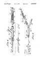
- FIG. 1is a side view of the catheter system in accordance with the present invention generally showing a guide wire, a working catheter, a Y-connector, and a torquing device unit to couple the working catheter to the guide wire as hereinafter described in greater detail;
- FIG. 2is a cross-sectional view of the torquing device in accordance with the present invention.
- FIGS. 3a, b, c, and dare diagrammatic illustrations of relative positions of the distal end of the guide wire having a shapable portion thereon, and the distal end of the working catheter showing how the working catheter may enable the steering of the guide wire in accordance with the present invention
- FIG. 4is a side view of the catheter system shown in FIG. 1 with the torquing device separated from the Y-connector, enabling independent longitudinal movement of the guide wire within the catheter;
- FIG. 5is a side view of the present invention including an alternative standard type Y connector and showing how manipulation of the guide wire within the working catheter is enabled when a torquing device is decoupled from the Y connector.
- FIG. 1there is shown a catheter system 10, including a guide wire 12, having a proximal end 14 and a distal end 16, the latter having a shapable flexible end portion 18 thereon, which may be of any suitable configuration, such as a fine, helically wound coiled wire or the like, and a working catheter 22 having a proximal end 24, a distal end 26, and an inside diameter 28.
- a guide wire 12having a proximal end 14 and a distal end 16 having a shapable flexible end portion 18 thereon, which may be of any suitable configuration, such as a fine, helically wound coiled wire or the like
- a working catheter 22having a proximal end 24, a distal end 26, and an inside diameter 28.
- an inflatable balloon 30Disposed at the distal end 26 of the working catheter 22 is an inflatable balloon 30 in a fluid communication with a port 34 via a working catheter lumen 36.
- the configuration of the working catheter 22, including balloon 30, as well as the guide wire 12,may be of any conventional design as is well known in the art.
- a radiopaque marker 40may be provided for use in determining the position of the distal end 26 of the working catheter 22 as it is advanced through a vascular system (not shown).
- control apparatus 50may be provided which includes a Y-connector 52, including the port 34 which provides means for inflating and deflating the balloon 30 by injecting or aspirating a fluid through the lumen 36 of the working catheter 22.
- the Y-connector 52, as well as a coupling 56 joining the working catheter 22 thereto,may be of conventional design.
- the outside diameter of the working catheter 22may be in creased in portions 60, 62 by the use of elastomeric coatings or metallic or polymeric sheathings for stiffening purposes to enhance the strength thereof.
- the coupling 56is attached, for example by means of threads 64, to the Y-connector body 66, the working catheter 22 is mounted in a non-rotatable relationship with the control apparatus 50.
- FIG. 2there is shown in cross-section the torquing device 78, which is part of the control apparatus 50, generally showing the adapter 72, along with a sleeve 82, and a shaft 84.
- the adapterincludes internal threads 88 for engagement with the coupling 70 of the control apparatus and including a lumen 90 therethrough for communication with the lumen 28 of the working catheter 22.
- a sleeve head 94Disposed within the adapter 72 for rotation therein is a sleeve head 94, having a face 96 pressed against a seal 98 for facilitating rotation.
- the sleeve 82includes a body 100 having threads 102 adapted for engagement with mating threads 104 on the shaft 84. When engaged, a seal 106 is pressed against the sleeve 94 to prevent a fluid which may be present in lumen 90 from passing therepast.
- Ribs 108 on a body portion 110facilitate the screwing of the shaft 84 into the sleeve 82 for compressing a compressible member, or tip 114, as it is forced against a tapered side diameter 116 of the sleeve 82, thus compressing the tip 114 onto the wire 12 and forming a seal for fluids within the lumen 90.
- the shaft 84 and the sleeve 82 and adapter 72provide means for coupling the working catheter 22 to the guide wire 12 and also means for enabling rotation of the guide wire 12 within the working catheter 22.
- a luer thread 120is provided on the body portion 110 and disposed in fluid communication with a central passage 122 of the shaft 84, which enables fluid to pass therethrough and into the lumen 90 of the adapter 72 and lumen 28 of the working catheter 22 for flushing or other purposes.
- working catheter 22in operation, may be slid over the guide wire 12 until a selected length of the shapable flexible end portion 18 extends beyond a working catheter tip 126, see FIGS. 3a, b, c and d. At that point, the working catheter 22 is removably coupled to the guide wire 12 by rotation, or twisting, of the shaft 84 into the sleeve 82, thereby compressing the tip 114 onto the guide wire 12.
- the working catheter guide wire 12is then inserted into a vascular system as in a conventional "fixed wire” system and thereafter, rotation of the sleeve 82, as shown by the arrow 128 (FIG.
- the shapable flexible end portion 18includes a length thereof "1", which is determined by the relative longitudinal placement of a distal end tip 132 with respect to the distal tip 126 of the working catheter 22 as shown in FIG. 3a.
- FIG. 3bshows the same length, 1, with the guide wire 12 end portion 18 oriented 180° from the orientation shown in FIG. 3a. Such orientations facilitate the advancement and manipulation of the guide wire 12 and working catheter 22 through the vascular system.
- the working catheter 22may be clamped to the guide wire 12 at a position at which the longitudinal placement of the distal tip 132 of the guide wire 12 with respect to the distal tip 126 of the working catheter 22 is substantially shorter, as may be necessary to facilitate advancement of the guide wire 12, with the working catheter 22 attached thereto, through various arcuate portions of the vascular system.
- FIGS. 4 and 5there is shown the torquer 72 decoupled with the Y-connector 52 and an alternative Y-connector 140 having a body 142 and port 144 for fluid access to the collector lumen 36 for inflating and deflating the balloon 30.
- the torquing device 78is shown decoupled to the Y-connectors 52, 140 in FIGS. 4 and 5.
- the guide wire 14may be moved in a sliding fashion within the working catheter 22 as indicated by the arrow 150, which results in adjusting the length, 1, of guide wire 12 projecting beyond the working catheter distal tip 126. In this manner the guide wire 14 may be advanced within a vascular system ahead of the working catheter 22.
- the torquing device 70is coupled to either of the Y-members 52, 140, the working catheter 22 may be advanced with or, manipulated with, the guide wire 12.
- a procedure for the insertion of a working catheter 22 through a vascular systemincludes the steps of inserting the guide wire 12, having the shapable end portion 18 into a vascular system (not shown).
- the shapable flexible end portionis used to direct, or steer, the guide wire 12 through the arcuate and bifurcated portions of the vascular system.
- the working catheter 22is inserted over the guide wire 12 and coupled to the guide wire 12 with a selectable length, 1, of the shapable flexible end portion 18 protruding from the working catheter 22.
- the working catheter 22may be disposed over the guide wire 12 and coupled thereto as hereinabove described before simultaneous insertion of the guide wire 12 and working catheter into the vascular system.
- the guide wire 12may be rotated within the working catheter 22 in order to orient the shapable flexible end portion to a position suitable for continued advancement of the guide wire 12 with the working catheter coupled thereto within the vascular system (see FIGS. 3a, b, c and d). With the proper orientation, the procedure then includes advancing the guide wire 12 and working catheter 22 in the vascular system.
Landscapes
- Health & Medical Sciences (AREA)
- Life Sciences & Earth Sciences (AREA)
- Biophysics (AREA)
- Pulmonology (AREA)
- Engineering & Computer Science (AREA)
- Anesthesiology (AREA)
- Biomedical Technology (AREA)
- Heart & Thoracic Surgery (AREA)
- Hematology (AREA)
- Animal Behavior & Ethology (AREA)
- General Health & Medical Sciences (AREA)
- Public Health (AREA)
- Veterinary Medicine (AREA)
- Media Introduction/Drainage Providing Device (AREA)
Abstract
Description
Claims (6)
Priority Applications (1)
| Application Number | Priority Date | Filing Date | Title |
|---|---|---|---|
| US07/863,525US5163911A (en) | 1990-10-31 | 1992-04-03 | Over-the-wire catheter |
Applications Claiming Priority (2)
| Application Number | Priority Date | Filing Date | Title |
|---|---|---|---|
| US60811090A | 1990-10-31 | 1990-10-31 | |
| US07/863,525US5163911A (en) | 1990-10-31 | 1992-04-03 | Over-the-wire catheter |
Related Parent Applications (1)
| Application Number | Title | Priority Date | Filing Date |
|---|---|---|---|
| US60811090AContinuation | 1990-10-31 | 1990-10-31 |
Publications (1)
| Publication Number | Publication Date |
|---|---|
| US5163911Atrue US5163911A (en) | 1992-11-17 |
Family
ID=27085678
Family Applications (1)
| Application Number | Title | Priority Date | Filing Date |
|---|---|---|---|
| US07/863,525Expired - Fee RelatedUS5163911A (en) | 1990-10-31 | 1992-04-03 | Over-the-wire catheter |
Country Status (1)
| Country | Link |
|---|---|
| US (1) | US5163911A (en) |
Cited By (30)
| Publication number | Priority date | Publication date | Assignee | Title |
|---|---|---|---|---|
| US5334185A (en)* | 1991-06-28 | 1994-08-02 | Giesy Consultants, Inc. | End-to-end instrument placement apparatus |
| US5334160A (en)* | 1992-05-04 | 1994-08-02 | Scimed Life Systems, Inc. | Intravascular catheter with sleeve and method for use thereof |
| US5352197A (en)* | 1992-03-18 | 1994-10-04 | The Spectranetics Corporation | Turn limiter for a catheter with twistable tip |
| US5396880A (en)* | 1992-04-08 | 1995-03-14 | Danek Medical, Inc. | Endoscope for direct visualization of the spine and epidural space |
| US5460185A (en)* | 1994-03-25 | 1995-10-24 | Cordis Corporation | Tool and method facilitating rapid PCTA catheter exchange |
| US5465716A (en)* | 1993-11-22 | 1995-11-14 | Avitall; Boaz | Catheter control handle |
| US5569204A (en)* | 1993-06-24 | 1996-10-29 | Schneider (Europe) A.G. | Aspiration catheter arrangement |
| US6363273B1 (en)* | 1999-12-22 | 2002-03-26 | Codman & Shurtleff, Inc. | Introducer element and method of using same |
| US20020065507A1 (en)* | 1996-05-20 | 2002-05-30 | Gholam-Reza Zadno-Azizi | Exchange method for emboli containment |
| US6398743B1 (en) | 2000-07-28 | 2002-06-04 | Mdc Investment Holdings, Inc. | Medical device for inserting a guide wire having a retractable needle |
| US6636758B2 (en) | 2001-05-01 | 2003-10-21 | Concentric Medical, Inc. | Marker wire and process for using it |
| US6638245B2 (en) | 2001-06-26 | 2003-10-28 | Concentric Medical, Inc. | Balloon catheter |
| US6702782B2 (en) | 2001-06-26 | 2004-03-09 | Concentric Medical, Inc. | Large lumen balloon catheter |
| US6786875B2 (en) | 2000-04-18 | 2004-09-07 | Mdc Investement Holdings, Inc. | Medical device with shield having a retractable needle |
| US6793648B2 (en) | 2000-08-03 | 2004-09-21 | Ev3 Inc. | Back-loading catheter |
| US20050070820A1 (en)* | 2003-09-30 | 2005-03-31 | Scimed Life Systems, Inc. | Side loading wire torquing device |
| US20050143770A1 (en)* | 2003-07-31 | 2005-06-30 | Carter Matthew P. | Distal wire stop |
| US20080015544A1 (en)* | 2006-04-21 | 2008-01-17 | Entellus Medical, Inc. | Method for accessing a sinus cavity and related anatomical features |
| US20090005754A1 (en)* | 2007-06-29 | 2009-01-01 | Wilson-Cook Medical Inc. | Distal wire stop having adjustable handle |
| US20090254151A1 (en)* | 2008-04-02 | 2009-10-08 | Boston Scientific Neuromodulation Corporation | Lead anchor for implantable devices and methods of manufacture and use |
| US20110071502A1 (en)* | 2008-05-22 | 2011-03-24 | Terumo Kabushiki Kaisha | Catheter retaining tool |
| US20110288477A1 (en)* | 2006-04-21 | 2011-11-24 | Entellus Medical, Inc. | Guide catheter and method of use |
| US20150105655A1 (en)* | 2004-12-28 | 2015-04-16 | St. Jude Medical, Atrial Fibrillation Division, Inc. | Five degree of freedom ultrasound catheter and catheter control handle |
| US9192748B2 (en) | 2010-05-07 | 2015-11-24 | Entellus Medical, Inc. | Sinus balloon dilation catheters and sinus surgury tools |
| US20160082227A1 (en)* | 2004-12-28 | 2016-03-24 | St. Jude Medical, Atrial Fibrillation Division, Inc. | Fixed dimensional and bi-directional steerable catheter control handle |
| US9320493B2 (en)* | 2014-07-08 | 2016-04-26 | Nadarasa Visveshwara | System and method for measuring fluidics in arteries |
| CN106794005A (en)* | 2014-07-08 | 2017-05-31 | 纳达拉萨·维斯费什瓦拉 | Systems and methods for measuring arterial fluids |
| US10390889B2 (en) | 2010-07-26 | 2019-08-27 | St Jude Medical International Holding S.Á R.L. | Removable navigation system and method for a medical device |
| WO2021051051A1 (en) | 2019-09-12 | 2021-03-18 | Free Flow Medical, Inc. | Devices, methods, and systems to treat chronic bronchitis |
| US12419664B2 (en) | 2019-09-12 | 2025-09-23 | Free Flow Medical, Inc. | Devices, methods, and systems to treat chronic bronchitis |
Citations (17)
| Publication number | Priority date | Publication date | Assignee | Title |
|---|---|---|---|---|
| US33166A (en)* | 1861-08-27 | Improvement in water-elevators | ||
| US3552384A (en)* | 1967-07-03 | 1971-01-05 | American Hospital Supply Corp | Controllable tip guide body and catheter |
| US4490421A (en)* | 1983-07-05 | 1984-12-25 | E. I. Du Pont De Nemours And Company | Balloon and manufacture thereof |
| US4540404A (en)* | 1983-01-19 | 1985-09-10 | Datascope Corp. | Balloon catheter with intrinsic introducer for percutaneous insertion into a blood vessel over a guide wire, and method of use |
| US4545390A (en)* | 1982-09-22 | 1985-10-08 | C. R. Bard, Inc. | Steerable guide wire for balloon dilatation procedure |
| US4573470A (en)* | 1984-05-30 | 1986-03-04 | Advanced Cardiovascular Systems, Inc. | Low-profile steerable intraoperative balloon dilitation catheter |
| US4615472A (en)* | 1985-06-19 | 1986-10-07 | Intravascular Surgical Instruments, Inc. | Catheter placement device |
| US4616653A (en)* | 1985-07-30 | 1986-10-14 | Advanced Cardiovascular Systems, Inc. | Balloon dilatation catheter with advanceable non-removable guide wire |
| US4619263A (en)* | 1984-05-30 | 1986-10-28 | Advanced Cardiovascular Systems, Inc. | Adjustable rotation limiter device for steerable dilatation catheters |
| EP0244955A1 (en)* | 1986-04-07 | 1987-11-11 | Advanced Cardiovascular Systems, Inc. | Multiple angioplasty apparatus |
| US4757827A (en)* | 1987-02-17 | 1988-07-19 | Versaflex Delivery Systems Inc. | Steerable guidewire with deflectable tip |
| US4763667A (en)* | 1986-09-19 | 1988-08-16 | Microvasive, Inc. | Tissue-penetrating catheter device |
| US4790331A (en)* | 1986-12-02 | 1988-12-13 | Sherwood Medical Company | Method for placement of catheter in a blood vessel |
| US4846174A (en)* | 1986-08-08 | 1989-07-11 | Scimed Life Systems, Inc. | Angioplasty dilating guide wire |
| US4957117A (en)* | 1988-11-03 | 1990-09-18 | Ramsey Foundation | One-handed percutaneous transluminal angioplasty steering device and method |
| US4960411A (en)* | 1984-09-18 | 1990-10-02 | Medtronic Versaflex, Inc. | Low profile sterrable soft-tip catheter |
| US5045061A (en)* | 1990-02-02 | 1991-09-03 | C. R. Bard, Inc. | Balloon catheter and locking guidewire system |
- 1992
- 1992-04-03USUS07/863,525patent/US5163911A/ennot_activeExpired - Fee Related
Patent Citations (17)
| Publication number | Priority date | Publication date | Assignee | Title |
|---|---|---|---|---|
| US33166A (en)* | 1861-08-27 | Improvement in water-elevators | ||
| US3552384A (en)* | 1967-07-03 | 1971-01-05 | American Hospital Supply Corp | Controllable tip guide body and catheter |
| US4545390A (en)* | 1982-09-22 | 1985-10-08 | C. R. Bard, Inc. | Steerable guide wire for balloon dilatation procedure |
| US4540404A (en)* | 1983-01-19 | 1985-09-10 | Datascope Corp. | Balloon catheter with intrinsic introducer for percutaneous insertion into a blood vessel over a guide wire, and method of use |
| US4490421A (en)* | 1983-07-05 | 1984-12-25 | E. I. Du Pont De Nemours And Company | Balloon and manufacture thereof |
| US4619263A (en)* | 1984-05-30 | 1986-10-28 | Advanced Cardiovascular Systems, Inc. | Adjustable rotation limiter device for steerable dilatation catheters |
| US4573470A (en)* | 1984-05-30 | 1986-03-04 | Advanced Cardiovascular Systems, Inc. | Low-profile steerable intraoperative balloon dilitation catheter |
| US4960411A (en)* | 1984-09-18 | 1990-10-02 | Medtronic Versaflex, Inc. | Low profile sterrable soft-tip catheter |
| US4615472A (en)* | 1985-06-19 | 1986-10-07 | Intravascular Surgical Instruments, Inc. | Catheter placement device |
| US4616653A (en)* | 1985-07-30 | 1986-10-14 | Advanced Cardiovascular Systems, Inc. | Balloon dilatation catheter with advanceable non-removable guide wire |
| EP0244955A1 (en)* | 1986-04-07 | 1987-11-11 | Advanced Cardiovascular Systems, Inc. | Multiple angioplasty apparatus |
| US4846174A (en)* | 1986-08-08 | 1989-07-11 | Scimed Life Systems, Inc. | Angioplasty dilating guide wire |
| US4763667A (en)* | 1986-09-19 | 1988-08-16 | Microvasive, Inc. | Tissue-penetrating catheter device |
| US4790331A (en)* | 1986-12-02 | 1988-12-13 | Sherwood Medical Company | Method for placement of catheter in a blood vessel |
| US4757827A (en)* | 1987-02-17 | 1988-07-19 | Versaflex Delivery Systems Inc. | Steerable guidewire with deflectable tip |
| US4957117A (en)* | 1988-11-03 | 1990-09-18 | Ramsey Foundation | One-handed percutaneous transluminal angioplasty steering device and method |
| US5045061A (en)* | 1990-02-02 | 1991-09-03 | C. R. Bard, Inc. | Balloon catheter and locking guidewire system |
Cited By (67)
| Publication number | Priority date | Publication date | Assignee | Title |
|---|---|---|---|---|
| US5334185A (en)* | 1991-06-28 | 1994-08-02 | Giesy Consultants, Inc. | End-to-end instrument placement apparatus |
| US5352197A (en)* | 1992-03-18 | 1994-10-04 | The Spectranetics Corporation | Turn limiter for a catheter with twistable tip |
| US5396880A (en)* | 1992-04-08 | 1995-03-14 | Danek Medical, Inc. | Endoscope for direct visualization of the spine and epidural space |
| US5334160A (en)* | 1992-05-04 | 1994-08-02 | Scimed Life Systems, Inc. | Intravascular catheter with sleeve and method for use thereof |
| US5569204A (en)* | 1993-06-24 | 1996-10-29 | Schneider (Europe) A.G. | Aspiration catheter arrangement |
| US5749858A (en)* | 1993-06-24 | 1998-05-12 | Schneider (Europe) A.G. | Method of using an aspiration catheter |
| US5465716A (en)* | 1993-11-22 | 1995-11-14 | Avitall; Boaz | Catheter control handle |
| US5460185A (en)* | 1994-03-25 | 1995-10-24 | Cordis Corporation | Tool and method facilitating rapid PCTA catheter exchange |
| US20050245866A1 (en)* | 1996-05-20 | 2005-11-03 | Medtronic Vascular, Inc. | Exchange method for emboli containment |
| US20020065507A1 (en)* | 1996-05-20 | 2002-05-30 | Gholam-Reza Zadno-Azizi | Exchange method for emboli containment |
| US6986778B2 (en) | 1996-05-20 | 2006-01-17 | Medtronic Vascular, Inc. | Exchange method for emboli containment |
| US6363273B1 (en)* | 1999-12-22 | 2002-03-26 | Codman & Shurtleff, Inc. | Introducer element and method of using same |
| US7153276B2 (en) | 2000-04-18 | 2006-12-26 | Mdc Investment Holdings, Inc. | Medical device with shield having a retractable needle |
| US6786875B2 (en) | 2000-04-18 | 2004-09-07 | Mdc Investement Holdings, Inc. | Medical device with shield having a retractable needle |
| US20050027256A1 (en)* | 2000-04-18 | 2005-02-03 | Barker John M. | Medical device with shield having a retractable needle |
| US6398743B1 (en) | 2000-07-28 | 2002-06-04 | Mdc Investment Holdings, Inc. | Medical device for inserting a guide wire having a retractable needle |
| US20040225259A1 (en)* | 2000-08-03 | 2004-11-11 | Ev3 Inc. | Back-loading catheter |
| US7572271B2 (en) | 2000-08-03 | 2009-08-11 | Ev3 Inc. | Back-loading catheter |
| US6793648B2 (en) | 2000-08-03 | 2004-09-21 | Ev3 Inc. | Back-loading catheter |
| US20090270909A1 (en)* | 2000-08-03 | 2009-10-29 | Ev3 Inc. | Back-loading catheter |
| US6636758B2 (en) | 2001-05-01 | 2003-10-21 | Concentric Medical, Inc. | Marker wire and process for using it |
| US6702782B2 (en) | 2001-06-26 | 2004-03-09 | Concentric Medical, Inc. | Large lumen balloon catheter |
| US6638245B2 (en) | 2001-06-26 | 2003-10-28 | Concentric Medical, Inc. | Balloon catheter |
| US7766049B2 (en) | 2001-06-26 | 2010-08-03 | Concentric Medical, Inc. | Balloon catheter |
| US20050143770A1 (en)* | 2003-07-31 | 2005-06-30 | Carter Matthew P. | Distal wire stop |
| US8211087B2 (en) | 2003-07-31 | 2012-07-03 | Cook Medical Technologies Llc | Distal wire stop |
| US7717865B2 (en) | 2003-09-30 | 2010-05-18 | Boston Scientific Scimed, Inc. | Side loading wire torquing device |
| US20100191152A1 (en)* | 2003-09-30 | 2010-07-29 | Boston Scientific Scimed, Inc. | Side Loading Wire Torquing Device |
| US20050070820A1 (en)* | 2003-09-30 | 2005-03-31 | Scimed Life Systems, Inc. | Side loading wire torquing device |
| US20160082227A1 (en)* | 2004-12-28 | 2016-03-24 | St. Jude Medical, Atrial Fibrillation Division, Inc. | Fixed dimensional and bi-directional steerable catheter control handle |
| US10035000B2 (en)* | 2004-12-28 | 2018-07-31 | St. Jude Medical, Atrial Fibrillation Division, Inc. | Fixed dimensional and bi-directional steerable catheter control handle |
| US10183149B2 (en)* | 2004-12-28 | 2019-01-22 | St. Jude Medical, Atrial Fibrillation Division, Inc. | Five degree of freedom ultrasound catheter and catheter control handle |
| US10960181B2 (en) | 2004-12-28 | 2021-03-30 | St. Jude Medical, Atrial Fibrillation Division, Inc. | Fixed dimensional and bi-directional steerable catheter control handle |
| US20150105655A1 (en)* | 2004-12-28 | 2015-04-16 | St. Jude Medical, Atrial Fibrillation Division, Inc. | Five degree of freedom ultrasound catheter and catheter control handle |
| US20110288477A1 (en)* | 2006-04-21 | 2011-11-24 | Entellus Medical, Inc. | Guide catheter and method of use |
| US20120190973A1 (en)* | 2006-04-21 | 2012-07-26 | Entellus Medical, Inc. | Method of confirming location of guide wire |
| US9775975B2 (en) | 2006-04-21 | 2017-10-03 | Entellus Medical, Inc. | Sinusitis treatment system and method of use |
| US8568439B2 (en)* | 2006-04-21 | 2013-10-29 | Entellus Medical, Inc. | Method of confirming location of guide wire |
| US8585729B2 (en) | 2006-04-21 | 2013-11-19 | Entellus Medical, Inc. | Method of dilating tissue of a sinus drainage pathway |
| US8585728B2 (en)* | 2006-04-21 | 2013-11-19 | Entellus Medical, Inc. | Method for accessing a sinus cavity and related anatomical features |
| US12053605B2 (en) | 2006-04-21 | 2024-08-06 | Entellus Medical, Inc. | Guide catheter and method of use |
| US8623043B1 (en)* | 2006-04-21 | 2014-01-07 | Entellus Medical, Inc. | Device and method for treatment of sinusitis |
| US8657846B2 (en)* | 2006-04-21 | 2014-02-25 | Entellus Medical, Inc. | Guide catheter and method of use |
| US10646701B2 (en) | 2006-04-21 | 2020-05-12 | Entellus Medical, Inc. | Guide catheter and method of use |
| US11547838B2 (en) | 2006-04-21 | 2023-01-10 | Entellus Medical, Inc. | Guide catheter and method of use |
| US9320876B2 (en) | 2006-04-21 | 2016-04-26 | Entellus Medical, Inc. | Sinusitis treatment system and method of use |
| US20080015544A1 (en)* | 2006-04-21 | 2008-01-17 | Entellus Medical, Inc. | Method for accessing a sinus cavity and related anatomical features |
| WO2009006145A1 (en)* | 2007-06-29 | 2009-01-08 | Wilson-Cook Medical Inc. | Distal wire stop having adjustable handle |
| US20090005754A1 (en)* | 2007-06-29 | 2009-01-01 | Wilson-Cook Medical Inc. | Distal wire stop having adjustable handle |
| US8292872B2 (en) | 2007-06-29 | 2012-10-23 | Cook Medical Technologies Llc | Distal wire stop having adjustable handle |
| US20090254151A1 (en)* | 2008-04-02 | 2009-10-08 | Boston Scientific Neuromodulation Corporation | Lead anchor for implantable devices and methods of manufacture and use |
| US9320891B2 (en)* | 2008-04-02 | 2016-04-26 | Boston Scientific Neuromodulation Corporation | Lead anchor for implantable devices and methods of manufacture and use |
| US20110071502A1 (en)* | 2008-05-22 | 2011-03-24 | Terumo Kabushiki Kaisha | Catheter retaining tool |
| US8585651B2 (en)* | 2008-05-22 | 2013-11-19 | Terumo Kabushiki Kaisha | Catheter retaining tool |
| US11207508B2 (en) | 2010-05-07 | 2021-12-28 | Entellus Medical, Inc. | Sinus balloon dilation catheters and sinus surgery tools |
| US12161827B2 (en) | 2010-05-07 | 2024-12-10 | Stryker Corporation | Sinus balloon dilation catheters and sinus surgery tools |
| US10238846B2 (en) | 2010-05-07 | 2019-03-26 | Entellus Medical, Inc. | Sinus balloon dilation catheters and sinus surgery tools |
| US9192748B2 (en) | 2010-05-07 | 2015-11-24 | Entellus Medical, Inc. | Sinus balloon dilation catheters and sinus surgury tools |
| US10390889B2 (en) | 2010-07-26 | 2019-08-27 | St Jude Medical International Holding S.Á R.L. | Removable navigation system and method for a medical device |
| US9320493B2 (en)* | 2014-07-08 | 2016-04-26 | Nadarasa Visveshwara | System and method for measuring fluidics in arteries |
| CN106794005B (en)* | 2014-07-08 | 2020-12-25 | 纳达拉萨·维斯费什瓦拉 | System and method for measuring arterial fluidics |
| US9504443B2 (en)* | 2014-07-08 | 2016-11-29 | Nadarasa Visveshwara | System and method for measuring fluidics in arteries |
| US9795359B2 (en) | 2014-07-08 | 2017-10-24 | Nadarasa Visveshwara | System and method for measuring fluidics in arteries |
| CN106794005A (en)* | 2014-07-08 | 2017-05-31 | 纳达拉萨·维斯费什瓦拉 | Systems and methods for measuring arterial fluids |
| WO2021051051A1 (en) | 2019-09-12 | 2021-03-18 | Free Flow Medical, Inc. | Devices, methods, and systems to treat chronic bronchitis |
| US12419664B2 (en) | 2019-09-12 | 2025-09-23 | Free Flow Medical, Inc. | Devices, methods, and systems to treat chronic bronchitis |
| US12426916B2 (en) | 2019-09-12 | 2025-09-30 | Free Flow Medical, Inc. | Devices, methods, and systems to treat chronic bronchitis |
Similar Documents
| Publication | Publication Date | Title |
|---|---|---|
| US5163911A (en) | Over-the-wire catheter | |
| CA1325150C (en) | Catheter y-connector with guidewire locking means | |
| US5290247A (en) | Intracoronary exchange apparatus and method | |
| US5059177A (en) | Triple lumen balloon catheter | |
| JP2939893B2 (en) | Interchangeable one piece-wire balloon catheter | |
| US5224939A (en) | Self locking guide catheter | |
| US5498239A (en) | Catheter placement by pressurizable tubular guiding core | |
| US5059176A (en) | Vascular system steerable guidewire with inflatable balloon | |
| US5163903A (en) | Catheter exchange system with detachable luer fitting | |
| US5882336A (en) | Dilation catheter | |
| US5207229A (en) | Flexibility steerable guidewire with inflatable balloon | |
| US5368567A (en) | Dilatation balloon catheter with infusion lumen | |
| US4884573A (en) | Very low profile angioplasty balloon catheter with capacity to use steerable, removable guidewire | |
| US4988356A (en) | Catheter and guidewire exchange system | |
| US5465733A (en) | Guide wire for catheters and method for its use | |
| US5468225A (en) | Rapid exchange catheter | |
| US5232445A (en) | Dilatation catheter | |
| US5035686A (en) | Catheter exchange system with detachable luer fitting | |
| US5902254A (en) | Cathether guidewire | |
| US4582181A (en) | Steerable dilatation catheter | |
| USRE33166E (en) | Steerable dilatation catheter | |
| AU2543288A (en) | Catheter for dilating stenotic lesions | |
| US5388590A (en) | Catheter exchange device | |
| EP0363203A2 (en) | Cardiac assist balloon and method of insertion | |
| CA2098570A1 (en) | Vascular catheter having low-profile distal end |
Legal Events
| Date | Code | Title | Description |
|---|---|---|---|
| AS | Assignment | Owner name:MITSUBISHI DENKI KABUSHIKI KAISHA, JAPAN Free format text:ASSIGNMENT OF ASSIGNORS INTEREST.;ASSIGNORS:KURAHASHI, KOICHIRO;MATSUMOTO, TAKAO;REEL/FRAME:005017/0149 Effective date:19860508 | |
| FEPP | Fee payment procedure | Free format text:PAYOR NUMBER ASSIGNED (ORIGINAL EVENT CODE: ASPN); ENTITY STATUS OF PATENT OWNER: LARGE ENTITY | |
| FEPP | Fee payment procedure | Free format text:PAYER NUMBER DE-ASSIGNED (ORIGINAL EVENT CODE: RMPN); ENTITY STATUS OF PATENT OWNER: LARGE ENTITY Free format text:PAYOR NUMBER ASSIGNED (ORIGINAL EVENT CODE: ASPN); ENTITY STATUS OF PATENT OWNER: LARGE ENTITY | |
| FPAY | Fee payment | Year of fee payment:4 | |
| AS | Assignment | Owner name:ADVANCED CARDIOVASCULAR SYSTEMS, INC., CALIFORNIA Free format text:ASSIGNMENT OF ASSIGNORS INTEREST;ASSIGNOR:BAXTER INTERNATIONAL INC.;REEL/FRAME:008239/0257 Effective date:19950810 | |
| REMI | Maintenance fee reminder mailed | ||
| LAPS | Lapse for failure to pay maintenance fees | ||
| FP | Lapsed due to failure to pay maintenance fee | Effective date:20001117 | |
| STCH | Information on status: patent discontinuation | Free format text:PATENT EXPIRED DUE TO NONPAYMENT OF MAINTENANCE FEES UNDER 37 CFR 1.362 |