US5163903A - Catheter exchange system with detachable luer fitting - Google Patents
Catheter exchange system with detachable luer fittingDownload PDFInfo
- Publication number
- US5163903A US5163903AUS07/737,321US73732191AUS5163903AUS 5163903 AUS5163903 AUS 5163903AUS 73732191 AUS73732191 AUS 73732191AUS 5163903 AUS5163903 AUS 5163903A
- Authority
- US
- United States
- Prior art keywords
- catheter
- shaft
- proximal end
- guidewire
- sheath
- Prior art date
- Legal status (The legal status is an assumption and is not a legal conclusion. Google has not performed a legal analysis and makes no representation as to the accuracy of the status listed.)
- Expired - Fee Related
Links
Images


Classifications
- A—HUMAN NECESSITIES
- A61—MEDICAL OR VETERINARY SCIENCE; HYGIENE
- A61M—DEVICES FOR INTRODUCING MEDIA INTO, OR ONTO, THE BODY; DEVICES FOR TRANSDUCING BODY MEDIA OR FOR TAKING MEDIA FROM THE BODY; DEVICES FOR PRODUCING OR ENDING SLEEP OR STUPOR
- A61M25/00—Catheters; Hollow probes
- A61M25/01—Introducing, guiding, advancing, emplacing or holding catheters
- A61M25/0169—Exchanging a catheter while keeping the guidewire in place
- A—HUMAN NECESSITIES
- A61—MEDICAL OR VETERINARY SCIENCE; HYGIENE
- A61M—DEVICES FOR INTRODUCING MEDIA INTO, OR ONTO, THE BODY; DEVICES FOR TRANSDUCING BODY MEDIA OR FOR TAKING MEDIA FROM THE BODY; DEVICES FOR PRODUCING OR ENDING SLEEP OR STUPOR
- A61M25/00—Catheters; Hollow probes
- A61M25/01—Introducing, guiding, advancing, emplacing or holding catheters
- A61M25/09—Guide wires
- A—HUMAN NECESSITIES
- A61—MEDICAL OR VETERINARY SCIENCE; HYGIENE
- A61M—DEVICES FOR INTRODUCING MEDIA INTO, OR ONTO, THE BODY; DEVICES FOR TRANSDUCING BODY MEDIA OR FOR TAKING MEDIA FROM THE BODY; DEVICES FOR PRODUCING OR ENDING SLEEP OR STUPOR
- A61M25/00—Catheters; Hollow probes
- A61M25/10—Balloon catheters
- A61M25/104—Balloon catheters used for angioplasty
- A—HUMAN NECESSITIES
- A61—MEDICAL OR VETERINARY SCIENCE; HYGIENE
- A61M—DEVICES FOR INTRODUCING MEDIA INTO, OR ONTO, THE BODY; DEVICES FOR TRANSDUCING BODY MEDIA OR FOR TAKING MEDIA FROM THE BODY; DEVICES FOR PRODUCING OR ENDING SLEEP OR STUPOR
- A61M25/00—Catheters; Hollow probes
- A61M25/01—Introducing, guiding, advancing, emplacing or holding catheters
- A61M25/09—Guide wires
- A61M2025/09008—Guide wires having a balloon
- A—HUMAN NECESSITIES
- A61—MEDICAL OR VETERINARY SCIENCE; HYGIENE
- A61M—DEVICES FOR INTRODUCING MEDIA INTO, OR ONTO, THE BODY; DEVICES FOR TRANSDUCING BODY MEDIA OR FOR TAKING MEDIA FROM THE BODY; DEVICES FOR PRODUCING OR ENDING SLEEP OR STUPOR
- A61M25/00—Catheters; Hollow probes
- A61M25/10—Balloon catheters
- A61M25/1011—Multiple balloon catheters
- A61M2025/1015—Multiple balloon catheters having two or more independently movable balloons where the distance between the balloons can be adjusted, e.g. two balloon catheters concentric to each other forming an adjustable multiple balloon catheter system
Definitions
- This inventionrelates to balloon dilatation catheter systems used in percutaneous transluminal coronary angioplasty.
- This inventionrelates to improvements in small diameter low profile dilatation catheters used in angioplasty and particularly coronary angioplasty. More particularly, the invention concerns the type of dilatation catheter which incorporates a wire-like shaft that is sufficiently torsionally rigid so as to be steerable thereby enabling the catheter to be selectively guided and steered to the desired location in the patient's coronary arteries.
- the cathetermay be exchanged in a well known procedure in which an exchange wire is substituted for the movable guidewire (or the length of the guidewire is extended with an extension wire); then the catheter is withdrawn over the exchange wire and the replacement catheter is threaded over the exchange wire and is thereby guided to the stenosis.
- a small diameter coronary dilatation catheterhas a shaft formed from stainless steel hypodermic tubing.
- the distal end of the shaftis of increasing flexibility and terminates in a highly flexible distal tip.
- the dilatation balloonis mounted to the shaft near the distal end.
- the interior of the balloonis in communication with the lumen extending through the hollow shaft.
- the balloonmay be inflated and deflated with a liquid by a syringe or other suitable inflation device attached to the proximal end of the shaft by a luer fitting carried at the proximal end of the shaft.
- the luer fittingis detachable from the hypodermic tubing so as to present a smooth continuous diameter at the proximal end of the catheter shaft.
- the luer fittingincludes a collet and nut arrangement by which the luer fitting can grip securely the tubular proximal end of the dilatation shaft.
- an extension wireis connected to the proximal end of the catheter shaft to extend its length. With its length so extended, a new catheter is advanced over the extension and along the shaft, following the shaft which thus serves as a guidewire to guide the catheter to the arterial branch to be treated.
- the small diameter dilatation cathetermay remain in the patient and may serve as a guidewire for the larger catheter should it be desired to direct the larger catheter to other regions in the coronary anatomy. Should it be desired to again use the small diameter dilatation catheter with integral guidewire, the outer catheter and extension wire can be removed and the luer fitting can be replaced on the proximal end of the small diameter dilatation catheter to enable it to be used again to dilate a narrow stenosis.
- an elongate flexible sheaththen is advanced over the extended length dilatation catheter and into the patient's coronary artery close to the site of the stenosis.
- the dilatation catheterthen is withdrawn through the sheath which remains in place.
- the new catheterthen can be advanced through the sheath directly to the location in the coronary artery to be treated. In this instance, the sheath serves to maintain direct and quick access to the branch artery being treated.
- a conventional dilatation catheter having a removable guidewiremay be exchanged for the small diameter fixed guidewire type of dilatation catheter described above.
- an extensionis fitted to the guidewire.
- the conventional dilatation catheteris removed from the patient, leaving the guidewire in place within the stenosis.
- the elongate flexible sheathdiscussed above, then is advanced over the guidewire to the location of the stenosis.
- the guidewire and extensionthen may be removed and the catheter with integral guidewire may be inserted into the sheath and be guided directly to the stenosis.
- Another object of the inventionis to provide a small diameter dilatation catheter having a guidewire like tubular shaft in which a luer fitting at the proximal end of the shaft is detachable.
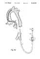
- FIG. 1is a fragmented illustration of a small diameter dilatation catheter having an integral guidewire-like shaft
- FIG. 2is an enlarged cross sectional illustration of the proximal end of the dilatation catheter shaft and the luer fitting;
- FIG. 3is an exploded illustration of the luer fitting
- FIG. 4Ais an illustration of the ends of the extension wire and the proximal end of the dilatation catheter after the luer fitting is removed from the dilatation catheter and before the catheter and wire are joined;
- FIG. 4Bis a cross-sectional illustration of the connection between the guidewire extension and proximal end of the catheter
- FIG. 5is a diagrammatic illustration of a larger catheter being passed over the shaft of the smaller diameter dilatation catheter, with the shaft serving as a guidewire to guide the larger catheter to the stenosis;
- FIG. 6is a diagrammatic illustration of the system of a flexible guiding sheath and inner sheath which may be used to facilitate exchanges of dilatation catheters having an integral guidewire;
- FIG. 7Ais a fragmented illustration of a coronary arterial system with a guide catheter in place and a dilatation catheter having a detachable luer fitting extending through the guide catheter and into the stenosis of a coronary artery;
- FIG. 7Bis an illustration similar to FIG. 7A with the proximal luer fitting of the catheter detached, a guidewire extension attached to the proximal end of the dilatation catheter and the dual guiding sheath arrangement advanced over the balloon dilatation catheter and into the coronary artery in proximity to the stenosis;
- FIG. 7Cis an illustration of the arterial and catheter system of FIG. 7B with the dilatation catheter and inner sheath removed, leaving the outer sheath in place and in readiness to receive another dilatation catheter having an integral guidewire.
- FIG. 1illustrates, generally, a small diameter balloon dilatation catheter 10.
- the cathetermay be of the order of 175 cm long. It includes an elongate shaft 12 formed from hypodermic tubing. A polymeric dilatation balloon 14 is mounted to the distal end of the catheter.
- the distal tip 16 of the catheteris of increasing flexibility in a distal direction and, typically, may be formed from a helical coil of radiopaque material.
- the shaft 12is sufficiently torsionally rigid so that it may transmit rotation from the proximal to the distal end of the catheter when the distal end is in the coronary arteries.
- the distal tip 16is formed so that it may be bent to a slight "J" shape illustrated in phantom at 17.
- a luer fitting 18is attached to the proximal end of the shaft 12 to enable attachment of an inflation device such as a syringe (not shown) to inflate and deflate the balloon 14 with a suitable fluid, such as radiopaque contrast liquid.
- an inflation devicesuch as a syringe (not shown) to inflate and deflate the balloon 14 with a suitable fluid, such as radiopaque contrast liquid.
- the luer fittingAs shown in FIGS. 2 and 3, the luer fitting, indicated generally at 18, includes a hub 20 having a socket 22 at its proximal end and a distally tapering bore 24 located distally of the socket 22.
- An aperture 26is formed at the distal end of the hub 20 and receives the proximal end of the catheter shaft 12.
- a collet 28 having distally extending fingers 30is provided with a central bore 32, also to receive the proximal end of the shaft 12 of the catheter.
- a compressible gasket 34formed from an elastomeric material such as silicone rubber, and also provided with a central bore 36, abuts the proximal face of the collet 28. The bore 36 of the gasket 34 receives the proximal end of the catheter shaft 12.
- a shaft stop member 38is provided with a central aperture 40 which tapers in a proximal direction.
- the bore 40tapers to a diameter that is smaller than the diameter of the proximal end of the catheter shaft 12 and, therefore, serves as an abutment for the proximal end of the shaft 12 as shown in FIG. 2, to prevent it from extending proximally beyond the stop member 38.
- the collet 28, gasket 34 and stop member 38are securely retained between the hub 20 and a luer body 42 having a threaded distal end 44 that screws into the socket 22 of the hub 20.
- the distal end of the luer body 42has a socket 46 which receives stop member 38, the gasket 34 and the proximal portion of the collet 28.
- the distal fingers 30 of the colletbear against the tapered bore 24 in the nut.
- the collet fingers 30constrict about the proximal end of the shaft 12 to securely lock the luer fitting 18 in place.
- the gasket 34also is compressed to effect a secure liquid seal about the shaft 12.
- the proximal end of the luer body 42has a luer socket 48 adapted to be connected to a syringe or other inflation/deflation device.
- the entire luer fitting 18may be detached from the proximal end of the shaft 12 simply by unscrewing the hub 20 and luer body 42 to release the collet and permit the assembly to slide off of the proximal end of the shaft 12.
- the proximal end of the shaft 12is formed to define a socket 50 adapted to receive the distal end of an extension wire 52 as illustrated in FIGS. 4A and 4B.
- the distal end of the extension wireis constructed in a manner that enables it to be detachably connected to the socket 50 in a manner described in detail in pending application Ser. No. 206,008 filed Jun. 13, 1988 entitled Removable Guidewire Extension, reference being made to said application for the full details of the extension wire connection.
- FIGS. 4A and 4Billustrate, somewhat diagrammatically, the nature of the connection.
- the distal end of the extension wirecarries a helical coil 54 that detachably connects within the socket 50.
- FIG. 5One manner in which the system may be used is illustrated in FIG. 5.
- a guide catheter 51is percutaneously inserted into a femoral artery 53 in the region of the groin and is advanced along the aorta 55 to place the distal tip of the guide catheter 51 at the entrance to the coronary artery 57.
- a balloon dilatation catheter 10is advanced through the guide catheter 51 and is manipulated to position its balloon 14 within the the stenosis 59 to be treated.
- the inflation deviceis detached from the luer fitting and the luer fitting 18 is detached from the catheter shaft 12 by unscrewing the luer body 42 to loosen the fitting 18.
- the extension wire 52then is attached to the socket 50 at the proximal end of the catheter shaft 12.
- the larger catheter 56then may be advanced over the extension wire 52 and the catheter shaft 12 which guides the larger catheter 56 through the coronary arteries 57 directly to the stenosis 59.
- the larger catheter 56may be passed over the balloon portion 14 of the smaller catheter 10.
- the balloon 58 of the larger catheter 56can be placed in the stenosis by advancing both the smaller and larger catheters 10, 56 distally until the balloon 58 of the larger catheter 56 is in the stenosis (if the coronary anatomy permits). The balloon 58 of the larger catheter 56 then may be inflated to perform the further dilatation with the larger size balloon.
- FIG. 7Aillustrates a guide catheter in place in the patient's coronary arterial system and a small diameter dilatation catheter 10 extending through the guide catheter 51, into a coronary artery 57 and into the stenosis 59.
- Such a catheter exchangerequires removal of the initial catheter 10.
- the luer fitting 18is detached and an extension wire 52 is fitted to the socket 50 at the proximal end of the shaft 12 (FIG. 7B). As shown in FIG.
- a tubular guide sheath assembly 60then is advanced over the extension wire 52 and catheter shaft 12.
- the sheath assembly 60is advanced to place its distal end within the coronary artery 57 as close to the stenosis 59 as possible.
- the catheter 10may be withdrawn, possibly together with a portion of the sheath assembly as described below.
- the remaining portion of the guide sheath assembly 60then provides a clear and direct path along which the replacement catheter may be advanced and guided directly to the stenosis 59.
- the foregoing sheath assembly 60is selected and dimensioned with reference to the catheters that are to be passed through it so that the catheters may pass freely.
- the guide sheath assembly 60may be formed in two elements including an inner sheath and an outer sheath.
- the outer sheathmay be used alone with relatively larger diameter catheters and the outer sheath and inner sheath may be used together with very small diameter catheters or guidewires.
- the inner diameter defined by the sheath arrangement, whether the outer sheath alone or the combination of outer and inner sheathshould be such as to permit free passage of the catheter or guidewire with which it is to be used but without having so much clearance that the ability of the sheath to be pushed over such a catheter or guidewire would be impaired.
- the guide sheath assembly 60is illustrated in FIG. 6 and includes an outer sheath 62 and an inner sheath 64 that is received in the outer sheath 62.
- Each of the outer and inner sheaths 62, 64is provided with a proximal fitting 66, 68.
- the fittingsar detachably connectable to each other with luer tapers.
- the inner sheath 64serves to fill sufficiently the annular space between the small diameter catheter shaft or guidewire and the inner lumen of the outer sheath 62 to provide axial strength or "pushability" for the sheath assembly as it is advanced over the catheter or guidewire.
- the inner sheath 64may be omitted and the procedure may be effected with the outer sheath alone.
- the inner sheath 64is removed to present the full diameter lumen of the outer sheath and to enable insertion of the replacement dilatation catheter 10 with integral guidewire.
- the small diameter catheter with integral guidewiremay be exchanged for a conventional balloon dilatation catheter having a removable guidewire.
- the small diameter catheter with integral guidewiremay be removed as described above in connection with FIGS. 7A-7C.
- a conventional guidewireis advanced through the sheath 62 so that its distal tip can extend through the stenosis 59.
- a guidewire extensionthen is attached to the proximal end of the guidewire.
- the sheath 62then may be withdrawn, the guidewire arrangement maintaining position in the stenosis.
- a conventional over the wire cathetercan be passed over the guidewire to direct its distal end directly to the stenosis.
- a conventional dilatation catheter having a removable guidewiremay be exchanged for a small diameter catheter having an integral guidewire.
- a guidewire extension 52may be attached to the proximal end of the guidewire.
- the conventional balloon dilatation catheterthen may be removed over the extended guidewire.
- a sheath assembly 60 including both the outer sheath 62 and inner sheath 64then is advanced over the guidewire to locate the distal end of the outer sheath 62 adjacent the stenosis 59.
- the inner sheath 64 and guidewirethen may be removed leaving the configuration shown in FIG. 7C of an open outer sheath 62 through which the small diameter catheter with integral guidewire may be advanced directly to the stenosis 59.
- the outer sheathmay be about 125 cm long and be approximately 0.058" outer diameter having a wall thickness of the order of 0.009".
- the outer sheath 62is formed to include a proximal portion 67 and a distal portion 69.
- the proximal portion 67preferably is formed from high density polyethylene and is stiffer than the distal portion 69 which preferably is formed from a more flexible linear low density polyethylene. The more flexible distal portion is desired so that the outer sheath 62 is flexible and can follow the tortuous coronary anatomy.
- the proximal section 67is about 100 cm long and the distal portion 69 is about 25 cm long.
- the proximal and distal portions 67, 69are joined at a heat bond, indicated at 70.
- a stainless steel helical coil 72is mounted on the outside of the distal end of the outer sheath 62 and is about 15 cm in length.
- the springmay be formed from wire about 0.002" diameter and serves to enhance the radiopacity of the distal portion of the outer sheath so that it may be visualized fluoroscopically.
- the coil 72preferably is coated with a lubricious material such as a polyurethane silicone blend.
- the coil 72is attached only at its ends to the distal section 69 by an appropriate adhesive, preferably cyanoacrylate. The individual coils between the ends of the coil 72 are spaced very slightly from each other so that the distal portion of the outer sheath in the region of the coil 72 remains highly flexible.
- the individual coilsUpon placement of an axial compressive load on the coil 72, the individual coils butt against each other to form a relatively rigid, inflexible tubular column. This is desirable when withdrawing a balloon catheter through the outer sheath to insure that the balloon, which will interfere with the distal tip of the catheter, will not cause column buckling of the distal tip of the catheter. Should there be sufficient interference between the balloon and the distal end of the catheter to cause any appreciable column compression, the coil 72 rigidifies to provide support.
- the spacing of the coilsshould be just sufficient to permit the coil to retain its flexibility when it is not under an axial compressive load. For example, a few ten thousandths of an inch spacing between coils should be sufficient.
- a soft distal tip 74is attached to the distal tip of the distal section 69, distally of the coil 72.
- the distal tip 74may project distally of the polyethylene distal section 69 approximately 2.5 mm. It may be formed from a soft elastomeric material, preferably one which is a styrene ethylene/butylene styrene(s-eb-s) block copolymer.
- the inner sheath 64which, for example, may be passed over a 0.016" or 0.018" diameter guidewire is approximately 0.034" outer diameter and may have an inner diameter of the order of 0.026".
- the distal tip of the inner sheath 64is tapered.
- the inner sheathis slightly longer than the outer sheath so that when the inner sheath is advanced fully into the outer sheath, the distal tip of the inner sheath will extend about 1.5 cm beyond the distal tip of the outer sheath.
- the luer fittings 68, 66, respectively, of the inner and outer sheaths 64, 62are injection molded onto the proximal ends of the tubular sheaths.
- the proximal luer fitting 68 of the inner sheath 64has a purging port 76 which communicates with the lumen of the luer fitting 66 on the outer sheath when the two sheaths are connected.
- the purging port 76permits air to be purged from the inner and outer sheaths simultaneously by flushing saline solution through the proximal luer fitting 68.
- the inventionprovides a means by which catheter and guidewire exchanges can be performed quickly and expediently with minimal risk to the patient and without losing catheter or guidewire position.
- the inventionenables such an exchange to be made for a catheter of the type having an integral, non-detachable guidewire as well as for a conventional movable guidewire catheter.
- balloon dilatation cathetersit should be understood that the advantages of the invention also may be used with other catheters having both movable guidewires and integral guidewires.
- the inventionmay be practised to effect catheter changes with laser catheters, heater probe catheters and the like.
Landscapes
- Health & Medical Sciences (AREA)
- Life Sciences & Earth Sciences (AREA)
- Heart & Thoracic Surgery (AREA)
- Hematology (AREA)
- Engineering & Computer Science (AREA)
- Anesthesiology (AREA)
- Biomedical Technology (AREA)
- Pulmonology (AREA)
- Biophysics (AREA)
- Animal Behavior & Ethology (AREA)
- General Health & Medical Sciences (AREA)
- Public Health (AREA)
- Veterinary Medicine (AREA)
- Vascular Medicine (AREA)
- Child & Adolescent Psychology (AREA)
- Media Introduction/Drainage Providing Device (AREA)
Abstract
Description
Claims (7)
Priority Applications (1)
| Application Number | Priority Date | Filing Date | Title |
|---|---|---|---|
| US07/737,321US5163903A (en) | 1989-01-27 | 1991-07-29 | Catheter exchange system with detachable luer fitting |
Applications Claiming Priority (2)
| Application Number | Priority Date | Filing Date | Title |
|---|---|---|---|
| US07/303,549US5035686A (en) | 1989-01-27 | 1989-01-27 | Catheter exchange system with detachable luer fitting |
| US07/737,321US5163903A (en) | 1989-01-27 | 1991-07-29 | Catheter exchange system with detachable luer fitting |
Related Parent Applications (1)
| Application Number | Title | Priority Date | Filing Date |
|---|---|---|---|
| US07/303,549ContinuationUS5035686A (en) | 1989-01-27 | 1989-01-27 | Catheter exchange system with detachable luer fitting |
Publications (1)
| Publication Number | Publication Date |
|---|---|
| US5163903Atrue US5163903A (en) | 1992-11-17 |
Family
ID=26973518
Family Applications (1)
| Application Number | Title | Priority Date | Filing Date |
|---|---|---|---|
| US07/737,321Expired - Fee RelatedUS5163903A (en) | 1989-01-27 | 1991-07-29 | Catheter exchange system with detachable luer fitting |
Country Status (1)
| Country | Link |
|---|---|
| US (1) | US5163903A (en) |
Cited By (53)
| Publication number | Priority date | Publication date | Assignee | Title |
|---|---|---|---|---|
| US5318535A (en)* | 1993-06-21 | 1994-06-07 | Baxter International Inc. | Low-profile dual-lumen perfusion balloon catheter with axially movable inner guide sheath |
| US5421348A (en)* | 1993-11-29 | 1995-06-06 | Cordis Corporation | Rotating guidewire extension system with mechanically locking extension wire |
| US5439445A (en)* | 1992-08-07 | 1995-08-08 | Boston Scientific Corporation | Support catheter assembly |
| US5441055A (en)* | 1994-06-27 | 1995-08-15 | Cordis Corporation | Guidewire extension wire and connector assembly |
| US5476472A (en)* | 1992-10-30 | 1995-12-19 | Interventional Therapeutics Corporation | Embolization device and apparatus including an introducer cartridge and a delivery catheter and method for delivering the embolization device |
| US5558635A (en)* | 1994-12-06 | 1996-09-24 | Medtronic, Inc. | Exchangeable guide system |
| US5741233A (en)* | 1995-10-20 | 1998-04-21 | Tfx Medical, Incorporated | Introducer device and methods of use thereof |
| US5882336A (en)* | 1994-12-30 | 1999-03-16 | Janacek; Jaroslav | Dilation catheter |
| US5951518A (en)* | 1997-10-31 | 1999-09-14 | Teleflex, Incorporated | Introducing device with flared sheath end |
| US6019777A (en) | 1997-04-21 | 2000-02-01 | Advanced Cardiovascular Systems, Inc. | Catheter and method for a stent delivery system |
| EP1181946A1 (en)* | 2000-08-04 | 2002-02-27 | Alan David Mogg | Catheter adapter |
| US6503244B2 (en) | 2001-03-07 | 2003-01-07 | Micro Therapeutics, Inc. | High pressure injection system |
| US6620149B1 (en) | 2000-10-05 | 2003-09-16 | Scimed Life Systems, Inc. | Corewire securement system |
| US7094218B2 (en) | 2004-03-18 | 2006-08-22 | C. R. Bard, Inc. | Valved catheter |
| US20070213812A1 (en)* | 2002-11-15 | 2007-09-13 | Webler William E | Apparatuses and methods for delivering/deploying a medical device in a vessel |
| US20080097395A1 (en)* | 2006-09-18 | 2008-04-24 | Boston Scientific Scimed, Inc. | Catheter shaft including a metallic tapered region |
| US20080183141A1 (en)* | 2007-01-26 | 2008-07-31 | Matthew Dickson Reavill | Long catheter infusion insertion method and apparatus |
| US20080228145A1 (en)* | 2007-03-15 | 2008-09-18 | Micrus Endovascular Corporation | Guidewire introducer and shaping tool |
| US7578803B2 (en) | 2004-03-18 | 2009-08-25 | C. R. Bard, Inc. | Multifunction adaptor for an open-ended catheter |
| US20090216185A1 (en)* | 2008-02-26 | 2009-08-27 | Boston Scientific Scimed, Inc. | Balloon catheter with durable tip portion |
| US7637893B2 (en) | 2004-04-30 | 2009-12-29 | C. R. Bard, Inc. | Valved sheath introducer for venous cannulation |
| US7713193B2 (en) | 2003-12-05 | 2010-05-11 | Onset Medical Corporation | Expandable percutaneous sheath |
| US20100145267A1 (en)* | 2008-11-10 | 2010-06-10 | Onset Medical Corporation | Expandable spinal sheath and method of use |
| US20100152650A1 (en)* | 2008-12-17 | 2010-06-17 | Cook Incorporated | Loading device for delivering an embolization coil into a microcatheter |
| US7854731B2 (en) | 2004-03-18 | 2010-12-21 | C. R. Bard, Inc. | Valved catheter |
| US7875019B2 (en) | 2005-06-20 | 2011-01-25 | C. R. Bard, Inc. | Connection system for multi-lumen catheter |
| US7883502B2 (en) | 2004-03-18 | 2011-02-08 | C. R. Bard, Inc. | Connector system for a proximally trimmable catheter |
| US7892203B2 (en) | 2004-09-09 | 2011-02-22 | Onset Medical Corporation | Expandable transluminal sheath |
| US20110086807A1 (en)* | 2008-05-01 | 2011-04-14 | Chia Soo | Fibromodulin formulation for reducing corneal scarring |
| US7981152B1 (en)* | 2004-12-10 | 2011-07-19 | Advanced Cardiovascular Systems, Inc. | Vascular delivery system for accessing and delivering devices into coronary sinus and other vascular sites |
| US8083728B2 (en) | 2004-03-18 | 2011-12-27 | C. R. Bard, Inc. | Multifunction adaptor for an open-ended catheter |
| US8177770B2 (en) | 2004-04-01 | 2012-05-15 | C. R. Bard, Inc. | Catheter connector system |
| US8177771B2 (en) | 2004-03-18 | 2012-05-15 | C. R. Bard, Inc. | Catheter connector |
| US8177760B2 (en) | 2004-05-12 | 2012-05-15 | C. R. Bard, Inc. | Valved connector |
| US8337484B2 (en) | 2009-06-26 | 2012-12-25 | C. R. Band, Inc. | Proximally trimmable catheter including pre-attached bifurcation and related methods |
| US8403890B2 (en) | 2004-11-29 | 2013-03-26 | C. R. Bard, Inc. | Reduced friction catheter introducer and method of manufacturing and using the same |
| US8579967B2 (en) | 2002-11-15 | 2013-11-12 | Advanced Cardiovascular Systems, Inc. | Valve aptation assist device |
| US8597277B2 (en) | 2004-09-09 | 2013-12-03 | Onset Medical Corporation | Expandable transluminal sheath |
| US8608702B2 (en) | 2007-10-19 | 2013-12-17 | C. R. Bard, Inc. | Introducer including shaped distal region |
| US8926564B2 (en) | 2004-11-29 | 2015-01-06 | C. R. Bard, Inc. | Catheter introducer including a valve and valve actuator |
| US8932260B2 (en) | 2004-11-29 | 2015-01-13 | C. R. Bard, Inc. | Reduced-friction catheter introducer and method of manufacturing and using the same |
| US9149602B2 (en) | 2005-04-22 | 2015-10-06 | Advanced Cardiovascular Systems, Inc. | Dual needle delivery system |
| US9241735B2 (en) | 2003-12-05 | 2016-01-26 | Onset Medical Corporation | Expandable percutaneous sheath |
| EP2603254A4 (en)* | 2010-08-12 | 2016-08-24 | Boston Scient Ltd | SYSTEM OF INFUSION FLOW AND FLUID COUPLING |
| US20170000607A1 (en)* | 2015-07-02 | 2017-01-05 | Boston Scientific Scimed, Inc. | Adjustable nosecone |
| US9597152B2 (en) | 2011-09-10 | 2017-03-21 | Cook Medical Technologies Llc | Control handles for medical devices |
| US9597483B2 (en) | 2004-11-29 | 2017-03-21 | C. R. Bard, Inc. | Reduced-friction catheter introducer and method of manufacturing and using the same |
| US9968762B2 (en) | 2012-08-08 | 2018-05-15 | Cook Medical Technologies Llc | Wire guide with multiple tips |
| US10252035B2 (en) | 2015-12-07 | 2019-04-09 | Cook Medical Techonologies Llc | Rotatable control handles for medical devices and methods of using rotatable control handles |
| US10349958B2 (en) | 2012-03-27 | 2019-07-16 | Cook Medical Technologies Llc | Lithotripsy probes and methods for performing lithotripsy |
| US11471647B2 (en) | 2014-11-07 | 2022-10-18 | C. R. Bard, Inc. | Connection system for tunneled catheters |
| CN116271456A (en)* | 2023-05-23 | 2023-06-23 | 杭州瑞维特医疗科技有限公司 | Medicine sacculus pipe subassembly |
| US11896782B2 (en) | 2017-08-23 | 2024-02-13 | C. R. Bard, Inc. | Priming and tunneling system for a retrograde catheter assembly |
Citations (20)
| Publication number | Priority date | Publication date | Assignee | Title |
|---|---|---|---|---|
| US3752510A (en)* | 1971-10-07 | 1973-08-14 | Sherwood Medical Ind Inc | Structure for connecting a flexible tube to a syringe |
| SU627828A1 (en)* | 1975-08-06 | 1978-10-15 | Borisenko Valentin A | Catheter |
| US4187848A (en)* | 1977-07-18 | 1980-02-12 | The Kendall Company | Adapter assembly |
| US4270778A (en)* | 1979-05-03 | 1981-06-02 | Sherwood Medical Industries Inc. | Tube connector with security means |
| US4290428A (en)* | 1978-09-01 | 1981-09-22 | Durand Alain J M | Catheter with bulb |
| US4299226A (en)* | 1979-08-08 | 1981-11-10 | Banka Vidya S | Coronary dilation method |
| US4323065A (en)* | 1980-01-17 | 1982-04-06 | Baxter Travenol Laboratories, Inc. | Attachable connector for catheter |
| US4467790A (en)* | 1981-04-13 | 1984-08-28 | Peter Schiff | Percutaneous balloon |
| WO1985004432A1 (en)* | 1984-04-03 | 1985-10-10 | Feldmühle Aktiengesellschaft | Aeration installation |
| US4547194A (en)* | 1984-03-16 | 1985-10-15 | Moorehead Harvey R | Hub assemblies and extensions for indwelling catheter tubes and method |
| WO1986006285A1 (en)* | 1985-05-02 | 1986-11-06 | C. R. Bard, Inc. | Microdilatation probe and system for performing angioplasty |
| EP0213748A1 (en)* | 1985-07-30 | 1987-03-11 | Advanced Cardiovascular Systems, Inc. | Dual dilatation catheter assembly and miniature balloon dilatation catheter for use therewith |
| GB2180454A (en)* | 1985-09-18 | 1987-04-01 | Bard Inc C R | Catheter exchange method and means therefor |
| WO1988000844A1 (en)* | 1986-08-08 | 1988-02-11 | Scimed Life Systems, Inc. | Angioplasty dilating guide wire |
| US4732163A (en)* | 1985-11-21 | 1988-03-22 | Sarcem S.A. | Remote controlled guide for a catheter |
| WO1988001885A1 (en)* | 1986-09-19 | 1988-03-24 | Versaflex Delivery Systems Inc. | Outer exchange catheter system |
| US4736733A (en)* | 1987-02-25 | 1988-04-12 | Medical Dynamics, Inc. | Endoscope with removable eyepiece |
| US4748982A (en)* | 1987-01-06 | 1988-06-07 | Advanced Cardiovascular Systems, Inc. | Reinforced balloon dilatation catheter with slitted exchange sleeve and method |
| US4848344A (en)* | 1987-11-13 | 1989-07-18 | Cook, Inc. | Balloon guide |
| US4955895A (en)* | 1986-12-23 | 1990-09-11 | Terumo Kabushiki Kaisha | Vasodilating catheter |
- 1991
- 1991-07-29USUS07/737,321patent/US5163903A/ennot_activeExpired - Fee Related
Patent Citations (20)
| Publication number | Priority date | Publication date | Assignee | Title |
|---|---|---|---|---|
| US3752510A (en)* | 1971-10-07 | 1973-08-14 | Sherwood Medical Ind Inc | Structure for connecting a flexible tube to a syringe |
| SU627828A1 (en)* | 1975-08-06 | 1978-10-15 | Borisenko Valentin A | Catheter |
| US4187848A (en)* | 1977-07-18 | 1980-02-12 | The Kendall Company | Adapter assembly |
| US4290428A (en)* | 1978-09-01 | 1981-09-22 | Durand Alain J M | Catheter with bulb |
| US4270778A (en)* | 1979-05-03 | 1981-06-02 | Sherwood Medical Industries Inc. | Tube connector with security means |
| US4299226A (en)* | 1979-08-08 | 1981-11-10 | Banka Vidya S | Coronary dilation method |
| US4323065A (en)* | 1980-01-17 | 1982-04-06 | Baxter Travenol Laboratories, Inc. | Attachable connector for catheter |
| US4467790A (en)* | 1981-04-13 | 1984-08-28 | Peter Schiff | Percutaneous balloon |
| US4547194A (en)* | 1984-03-16 | 1985-10-15 | Moorehead Harvey R | Hub assemblies and extensions for indwelling catheter tubes and method |
| WO1985004432A1 (en)* | 1984-04-03 | 1985-10-10 | Feldmühle Aktiengesellschaft | Aeration installation |
| WO1986006285A1 (en)* | 1985-05-02 | 1986-11-06 | C. R. Bard, Inc. | Microdilatation probe and system for performing angioplasty |
| EP0213748A1 (en)* | 1985-07-30 | 1987-03-11 | Advanced Cardiovascular Systems, Inc. | Dual dilatation catheter assembly and miniature balloon dilatation catheter for use therewith |
| GB2180454A (en)* | 1985-09-18 | 1987-04-01 | Bard Inc C R | Catheter exchange method and means therefor |
| US4732163A (en)* | 1985-11-21 | 1988-03-22 | Sarcem S.A. | Remote controlled guide for a catheter |
| WO1988000844A1 (en)* | 1986-08-08 | 1988-02-11 | Scimed Life Systems, Inc. | Angioplasty dilating guide wire |
| WO1988001885A1 (en)* | 1986-09-19 | 1988-03-24 | Versaflex Delivery Systems Inc. | Outer exchange catheter system |
| US4955895A (en)* | 1986-12-23 | 1990-09-11 | Terumo Kabushiki Kaisha | Vasodilating catheter |
| US4748982A (en)* | 1987-01-06 | 1988-06-07 | Advanced Cardiovascular Systems, Inc. | Reinforced balloon dilatation catheter with slitted exchange sleeve and method |
| US4736733A (en)* | 1987-02-25 | 1988-04-12 | Medical Dynamics, Inc. | Endoscope with removable eyepiece |
| US4848344A (en)* | 1987-11-13 | 1989-07-18 | Cook, Inc. | Balloon guide |
Non-Patent Citations (4)
| Title |
|---|
| "Abdominal Aortography: A New Catheter Tip Closing Obturator for Percutaneous Technique", Straube et al., Radiology, vol. 81, No. 2, pp. 264-266, Aug. 1963. |
| Abdominal Aortography: A New Catheter Tip Closing Obturator for Percutaneous Technique , Straube et al., Radiology, vol. 81, No. 2, pp. 264 266, Aug. 1963.* |
| Page from USCI 1969 Products Catalog Straube Tip Occluder Assembly .* |
| Page from USCI 1969 Products Catalog--"Straube Tip Occluder Assembly". |
Cited By (92)
| Publication number | Priority date | Publication date | Assignee | Title |
|---|---|---|---|---|
| US5439445A (en)* | 1992-08-07 | 1995-08-08 | Boston Scientific Corporation | Support catheter assembly |
| US5476472A (en)* | 1992-10-30 | 1995-12-19 | Interventional Therapeutics Corporation | Embolization device and apparatus including an introducer cartridge and a delivery catheter and method for delivering the embolization device |
| US5318535A (en)* | 1993-06-21 | 1994-06-07 | Baxter International Inc. | Low-profile dual-lumen perfusion balloon catheter with axially movable inner guide sheath |
| US5421348A (en)* | 1993-11-29 | 1995-06-06 | Cordis Corporation | Rotating guidewire extension system with mechanically locking extension wire |
| US5441055A (en)* | 1994-06-27 | 1995-08-15 | Cordis Corporation | Guidewire extension wire and connector assembly |
| US5558635A (en)* | 1994-12-06 | 1996-09-24 | Medtronic, Inc. | Exchangeable guide system |
| US5882336A (en)* | 1994-12-30 | 1999-03-16 | Janacek; Jaroslav | Dilation catheter |
| US5741233A (en)* | 1995-10-20 | 1998-04-21 | Tfx Medical, Incorporated | Introducer device and methods of use thereof |
| US6217586B1 (en) | 1997-04-21 | 2001-04-17 | Advanced Cardiovascular Systems, Inc. | Catheter and method for a stent delivery system |
| US6019777A (en) | 1997-04-21 | 2000-02-01 | Advanced Cardiovascular Systems, Inc. | Catheter and method for a stent delivery system |
| EP0873730A3 (en)* | 1997-04-21 | 2000-05-24 | Advanced Cardiovascular Systems, Inc. | Catheter and method for a stent delivery system |
| US5951518A (en)* | 1997-10-31 | 1999-09-14 | Teleflex, Incorporated | Introducing device with flared sheath end |
| EP1181946A1 (en)* | 2000-08-04 | 2002-02-27 | Alan David Mogg | Catheter adapter |
| US6676652B2 (en) | 2000-08-04 | 2004-01-13 | Alan David Mogg | Catheter adapter |
| US6620149B1 (en) | 2000-10-05 | 2003-09-16 | Scimed Life Systems, Inc. | Corewire securement system |
| US6503244B2 (en) | 2001-03-07 | 2003-01-07 | Micro Therapeutics, Inc. | High pressure injection system |
| US8187324B2 (en) | 2002-11-15 | 2012-05-29 | Advanced Cardiovascular Systems, Inc. | Telescoping apparatus for delivering and adjusting a medical device in a vessel |
| US20070213812A1 (en)* | 2002-11-15 | 2007-09-13 | Webler William E | Apparatuses and methods for delivering/deploying a medical device in a vessel |
| US8579967B2 (en) | 2002-11-15 | 2013-11-12 | Advanced Cardiovascular Systems, Inc. | Valve aptation assist device |
| US10349976B2 (en) | 2003-12-05 | 2019-07-16 | Onset Medical, Inc. | Expandable percutaneous sheath |
| US7713193B2 (en) | 2003-12-05 | 2010-05-11 | Onset Medical Corporation | Expandable percutaneous sheath |
| US9241735B2 (en) | 2003-12-05 | 2016-01-26 | Onset Medical Corporation | Expandable percutaneous sheath |
| US8282664B2 (en) | 2003-12-05 | 2012-10-09 | Onset Medical Corporation | Expandable percutaneous sheath |
| US7780692B2 (en) | 2003-12-05 | 2010-08-24 | Onset Medical Corporation | Expandable percutaneous sheath |
| US8177771B2 (en) | 2004-03-18 | 2012-05-15 | C. R. Bard, Inc. | Catheter connector |
| US7854731B2 (en) | 2004-03-18 | 2010-12-21 | C. R. Bard, Inc. | Valved catheter |
| US7883502B2 (en) | 2004-03-18 | 2011-02-08 | C. R. Bard, Inc. | Connector system for a proximally trimmable catheter |
| US7578803B2 (en) | 2004-03-18 | 2009-08-25 | C. R. Bard, Inc. | Multifunction adaptor for an open-ended catheter |
| US8083728B2 (en) | 2004-03-18 | 2011-12-27 | C. R. Bard, Inc. | Multifunction adaptor for an open-ended catheter |
| US8523840B2 (en) | 2004-03-18 | 2013-09-03 | C. R. Bard, Inc. | Connector system for a proximally trimmable catheter |
| US7094218B2 (en) | 2004-03-18 | 2006-08-22 | C. R. Bard, Inc. | Valved catheter |
| US8177770B2 (en) | 2004-04-01 | 2012-05-15 | C. R. Bard, Inc. | Catheter connector system |
| US7637893B2 (en) | 2004-04-30 | 2009-12-29 | C. R. Bard, Inc. | Valved sheath introducer for venous cannulation |
| US10307182B2 (en) | 2004-04-30 | 2019-06-04 | C. R. Bard, Inc. | Valved sheath introducer for venous cannulation |
| US8720065B2 (en) | 2004-04-30 | 2014-05-13 | C. R. Bard, Inc. | Valved sheath introducer for venous cannulation |
| US9108033B2 (en) | 2004-04-30 | 2015-08-18 | C. R. Bard, Inc. | Valved sheath introducer for venous cannulation |
| US8177760B2 (en) | 2004-05-12 | 2012-05-15 | C. R. Bard, Inc. | Valved connector |
| US9801619B2 (en) | 2004-09-09 | 2017-10-31 | Onset Medical Corporation | Expandable transluminal sheath |
| US8348892B2 (en) | 2004-09-09 | 2013-01-08 | Onset Medical Corporation | Expandable transluminal sheath |
| US7892203B2 (en) | 2004-09-09 | 2011-02-22 | Onset Medical Corporation | Expandable transluminal sheath |
| US8597277B2 (en) | 2004-09-09 | 2013-12-03 | Onset Medical Corporation | Expandable transluminal sheath |
| US8764704B2 (en) | 2004-09-09 | 2014-07-01 | Onset Medical Corporation | Expandable transluminal sheath |
| US8403890B2 (en) | 2004-11-29 | 2013-03-26 | C. R. Bard, Inc. | Reduced friction catheter introducer and method of manufacturing and using the same |
| US9283351B2 (en) | 2004-11-29 | 2016-03-15 | C. R. Bard, Inc. | Reduced friction catheter introducer and method of manufacturing and using the same |
| US9078998B2 (en) | 2004-11-29 | 2015-07-14 | C. R. Bard, Inc. | Catheter introducer including a valve and valve actuator |
| US10398879B2 (en) | 2004-11-29 | 2019-09-03 | C. R. Bard, Inc. | Reduced-friction catheter introducer and method of manufacturing and using the same |
| US8932260B2 (en) | 2004-11-29 | 2015-01-13 | C. R. Bard, Inc. | Reduced-friction catheter introducer and method of manufacturing and using the same |
| US9101737B2 (en) | 2004-11-29 | 2015-08-11 | C. R. Bard, Inc. | Reduced friction catheter introducer and method of manufacturing and using the same |
| US8926564B2 (en) | 2004-11-29 | 2015-01-06 | C. R. Bard, Inc. | Catheter introducer including a valve and valve actuator |
| US9278188B2 (en) | 2004-11-29 | 2016-03-08 | C. R. Bard, Inc. | Catheter introducer including a valve and valve actuator |
| US9597483B2 (en) | 2004-11-29 | 2017-03-21 | C. R. Bard, Inc. | Reduced-friction catheter introducer and method of manufacturing and using the same |
| US7981152B1 (en)* | 2004-12-10 | 2011-07-19 | Advanced Cardiovascular Systems, Inc. | Vascular delivery system for accessing and delivering devices into coronary sinus and other vascular sites |
| US9950144B2 (en) | 2005-04-22 | 2018-04-24 | Advanced Cardiovascular Systems, Inc. | Dual needle delivery system |
| US9149602B2 (en) | 2005-04-22 | 2015-10-06 | Advanced Cardiovascular Systems, Inc. | Dual needle delivery system |
| US8617138B2 (en) | 2005-06-20 | 2013-12-31 | C. R. Bard, Inc. | Connection system for multi-lumen catheter |
| US7875019B2 (en) | 2005-06-20 | 2011-01-25 | C. R. Bard, Inc. | Connection system for multi-lumen catheter |
| US8852168B2 (en) | 2005-06-20 | 2014-10-07 | C. R. Bard, Inc. | Connection system for multi-lumen catheter |
| US8206376B2 (en) | 2005-06-20 | 2012-06-26 | C. R. Bard, Inc. | Connection system for multi-lumen catheter |
| US9339628B2 (en) | 2006-09-18 | 2016-05-17 | Boston Scientific Scimed, Inc. | Catheter shaft including a metallic tapered region |
| US8574219B2 (en) | 2006-09-18 | 2013-11-05 | Boston Scientific Scimed, Inc. | Catheter shaft including a metallic tapered region |
| US20080097395A1 (en)* | 2006-09-18 | 2008-04-24 | Boston Scientific Scimed, Inc. | Catheter shaft including a metallic tapered region |
| US20080183141A1 (en)* | 2007-01-26 | 2008-07-31 | Matthew Dickson Reavill | Long catheter infusion insertion method and apparatus |
| US9925356B2 (en) | 2007-01-26 | 2018-03-27 | Matthew Dickson Reavill | Long catheter infusion insertion method and apparatus |
| US8231601B2 (en)* | 2007-01-26 | 2012-07-31 | Matthew Dickson Reavill | Long catheter infusion insertion method and apparatus |
| WO2008115430A1 (en)* | 2007-03-15 | 2008-09-25 | Micrus Endovascular Corporation | Improved guidewire introducer and shaping tool |
| US20080228145A1 (en)* | 2007-03-15 | 2008-09-18 | Micrus Endovascular Corporation | Guidewire introducer and shaping tool |
| US8608702B2 (en) | 2007-10-19 | 2013-12-17 | C. R. Bard, Inc. | Introducer including shaped distal region |
| US20090216185A1 (en)* | 2008-02-26 | 2009-08-27 | Boston Scientific Scimed, Inc. | Balloon catheter with durable tip portion |
| US20110086807A1 (en)* | 2008-05-01 | 2011-04-14 | Chia Soo | Fibromodulin formulation for reducing corneal scarring |
| US10016452B2 (en) | 2008-05-01 | 2018-07-10 | The Regents Of The University Of California | Fibromodulin formulation for reducing corneal scarring |
| US20100145267A1 (en)* | 2008-11-10 | 2010-06-10 | Onset Medical Corporation | Expandable spinal sheath and method of use |
| US9044577B2 (en) | 2008-11-10 | 2015-06-02 | Onset Medical Corporation | Expandable spinal sheath and method of use |
| US7951110B2 (en) | 2008-11-10 | 2011-05-31 | Onset Medical Corporation | Expandable spinal sheath and method of use |
| US8043325B2 (en)* | 2008-12-17 | 2011-10-25 | Cook Medical Technologies Llc | Loading device for delivering an embolization coil into a microcatheter |
| US20100152650A1 (en)* | 2008-12-17 | 2010-06-17 | Cook Incorporated | Loading device for delivering an embolization coil into a microcatheter |
| US8337484B2 (en) | 2009-06-26 | 2012-12-25 | C. R. Band, Inc. | Proximally trimmable catheter including pre-attached bifurcation and related methods |
| EP2603254A4 (en)* | 2010-08-12 | 2016-08-24 | Boston Scient Ltd | SYSTEM OF INFUSION FLOW AND FLUID COUPLING |
| EP2753250B1 (en)* | 2011-09-10 | 2019-03-20 | Cook Medical Technologies LLC | Control handles for medical devices |
| US9597152B2 (en) | 2011-09-10 | 2017-03-21 | Cook Medical Technologies Llc | Control handles for medical devices |
| US10925623B2 (en) | 2011-09-10 | 2021-02-23 | Cook Medical Technologies Llc | Control handles for medical devices |
| US10349958B2 (en) | 2012-03-27 | 2019-07-16 | Cook Medical Technologies Llc | Lithotripsy probes and methods for performing lithotripsy |
| US10821269B2 (en) | 2012-08-08 | 2020-11-03 | Cook Medical Technologies Llc | Wire guide with multiple tips |
| US9968762B2 (en) | 2012-08-08 | 2018-05-15 | Cook Medical Technologies Llc | Wire guide with multiple tips |
| US11471647B2 (en) | 2014-11-07 | 2022-10-18 | C. R. Bard, Inc. | Connection system for tunneled catheters |
| US10335277B2 (en)* | 2015-07-02 | 2019-07-02 | Boston Scientific Scimed Inc. | Adjustable nosecone |
| US20170000607A1 (en)* | 2015-07-02 | 2017-01-05 | Boston Scientific Scimed, Inc. | Adjustable nosecone |
| US11730595B2 (en) | 2015-07-02 | 2023-08-22 | Boston Scientific Scimed, Inc. | Adjustable nosecone |
| US12318292B2 (en) | 2015-07-02 | 2025-06-03 | Boston Scientific Scimed, Inc. | Adjustable nosecone |
| US10252035B2 (en) | 2015-12-07 | 2019-04-09 | Cook Medical Techonologies Llc | Rotatable control handles for medical devices and methods of using rotatable control handles |
| US11896782B2 (en) | 2017-08-23 | 2024-02-13 | C. R. Bard, Inc. | Priming and tunneling system for a retrograde catheter assembly |
| CN116271456A (en)* | 2023-05-23 | 2023-06-23 | 杭州瑞维特医疗科技有限公司 | Medicine sacculus pipe subassembly |
| CN116271456B (en)* | 2023-05-23 | 2023-08-11 | 杭州瑞维特医疗科技有限公司 | Medicine sacculus pipe subassembly |
Similar Documents
| Publication | Publication Date | Title |
|---|---|---|
| US5163903A (en) | Catheter exchange system with detachable luer fitting | |
| US5035686A (en) | Catheter exchange system with detachable luer fitting | |
| US5045061A (en) | Balloon catheter and locking guidewire system | |
| US5281200A (en) | Multiple component balloon catheter system and stenosis treatment procedure | |
| EP0773810B1 (en) | Telescoping catheter | |
| US5135535A (en) | Catheter system with catheter and guidewire exchange | |
| EP0629417B1 (en) | Low-profile dual-lumen perfusion balloon catheter with axially movable inner guide sheath | |
| US5290247A (en) | Intracoronary exchange apparatus and method | |
| US5348545A (en) | Guiding catheter for the right coronary artery | |
| US6254549B1 (en) | Guidewire replacement device with flexible intermediate section | |
| US4947864A (en) | Guidewire exchange catheter | |
| US5195971A (en) | Perfusion type dilatation catheter | |
| US5322508A (en) | Guidewire fluid delivery system and method of use | |
| US5807355A (en) | Catheter with rapid exchange and OTW operative modes | |
| US5709658A (en) | Rapid exchange type over-the-wire catheter | |
| EP0441384B1 (en) | Readily exchangeable perfusion catheter | |
| CA2008784C (en) | Rapidly exchangeable coronary catheter | |
| US5042985A (en) | Dilatation catheter suitable for peripheral arteries | |
| CA1315632C (en) | Kissing balloon catheter | |
| US5730734A (en) | Catheter systems with interchangeable parts | |
| US6299595B1 (en) | Catheters having rapid-exchange and over-the-wire operating modes | |
| EP0620750B1 (en) | Guidewire replacement device | |
| WO1993014802A1 (en) | Left coronary guiding catheter | |
| US6099496A (en) | Catheter having a variable length shaft segment and method of use | |
| US20040176792A1 (en) | Device and method for advancing a wire |
Legal Events
| Date | Code | Title | Description |
|---|---|---|---|
| FEPP | Fee payment procedure | Free format text:PAYOR NUMBER ASSIGNED (ORIGINAL EVENT CODE: ASPN); ENTITY STATUS OF PATENT OWNER: LARGE ENTITY | |
| FPAY | Fee payment | Year of fee payment:4 | |
| AS | Assignment | Owner name:ARTERIAL VASCULAR ENGINEERING, INC., CALIFORNIA Free format text:ASSIGNMENT OF ASSIGNORS INTEREST;ASSIGNOR:C.R. BARD, INC.;REEL/FRAME:010144/0691 Effective date:19981001 Owner name:MEDTRONIC AVE, INC., CALIFORNIA Free format text:MERGER;ASSIGNORS:MAV MERGER CORPORATION;ARTERIAL VASCULAR ENGINEERING, INC.;REEL/FRAME:010144/0720 Effective date:19990128 | |
| FEPP | Fee payment procedure | Free format text:PAYER NUMBER DE-ASSIGNED (ORIGINAL EVENT CODE: RMPN); ENTITY STATUS OF PATENT OWNER: LARGE ENTITY Free format text:PAYOR NUMBER ASSIGNED (ORIGINAL EVENT CODE: ASPN); ENTITY STATUS OF PATENT OWNER: LARGE ENTITY | |
| FPAY | Fee payment | Year of fee payment:8 | |
| REMI | Maintenance fee reminder mailed | ||
| LAPS | Lapse for failure to pay maintenance fees | ||
| STCH | Information on status: patent discontinuation | Free format text:PATENT EXPIRED DUE TO NONPAYMENT OF MAINTENANCE FEES UNDER 37 CFR 1.362 | |
| FP | Lapsed due to failure to pay maintenance fee | Effective date:20041117 |