US5163722A - Connection apparatus with ferrule forming structure - Google Patents
Connection apparatus with ferrule forming structureDownload PDFInfo
- Publication number
- US5163722A US5163722AUS07/736,516US73651691AUS5163722AUS 5163722 AUS5163722 AUS 5163722AUS 73651691 AUS73651691 AUS 73651691AUS 5163722 AUS5163722 AUS 5163722A
- Authority
- US
- United States
- Prior art keywords
- ferrule
- conduit
- follower
- base
- bore
- Prior art date
- Legal status (The legal status is an assumption and is not a legal conclusion. Google has not performed a legal analysis and makes no representation as to the accuracy of the status listed.)
- Expired - Lifetime
Links
Images
Classifications
- F—MECHANICAL ENGINEERING; LIGHTING; HEATING; WEAPONS; BLASTING
- F16—ENGINEERING ELEMENTS AND UNITS; GENERAL MEASURES FOR PRODUCING AND MAINTAINING EFFECTIVE FUNCTIONING OF MACHINES OR INSTALLATIONS; THERMAL INSULATION IN GENERAL
- F16L—PIPES; JOINTS OR FITTINGS FOR PIPES; SUPPORTS FOR PIPES, CABLES OR PROTECTIVE TUBING; MEANS FOR THERMAL INSULATION IN GENERAL
- F16L37/00—Couplings of the quick-acting type
- F16L37/24—Couplings of the quick-acting type in which the connection is made by inserting one member axially into the other and rotating it to a limited extent, e.g. with bayonet-action
- F16L37/242—Couplings of the quick-acting type in which the connection is made by inserting one member axially into the other and rotating it to a limited extent, e.g. with bayonet-action in which the rotation takes place between the eccentric parts
Definitions
- the present inventionrelates to an improved apparatus for effecting gas-tight communications between first and second members having bores for the passage of fluid. More particularly, the present invention relates to an improved high-temperature, low-pressure connection for affecting fluid-tight communication between such members.
- connection shown in U.S. Pat. No. 4,991,883 to R. D. Wordenwhich is incorporated herein by reference.
- the connection shown in the '883 patentprovides a fluid tight connection in spite of very wide temperature changes and operation at high temperatures which subjects the mechanical components of this connection to considerable expansion and contraction.
- a fused quartz springis used as a biasing element which maintains a constant biasing force onto a sealing ferrule which seals between an inner conduit containing a fluid and an outer sealing surface to maintain the seal in the presence of wide temperature variations and/or operation at high temperatures.
- An object of the present inventionis to provide an improved, high temperature connector which may use a high temperature biasing means to apply a constant force on a sealing ferrule when using an undersize conduit with respect to the sealing ferrule.
- Another object of the present inventionis to provide a quick-lock adaptor for high temperature connectors that permits a speedy connection to any standard tubing fitting.
- a preferred embodiment of the present inventionprovides a ferrule forming screw which can be used to apply sufficient force on the seal ferrule to create an initial seal around an undersize conduit. After an initial seal is made, a biasing spring can be used thereafter to maintain the seal as the connection is subject to high temperatures and/or wide variations in temperatures. In operation, the ferrule forming screw may be backed-off after an initial seal is made.
- a spring biasis used to secure a locking pin into a recessed portion of a groove utilizing the same high-temperature biasing spring which is used to maintain sealing force during high temperature operations during wide variations in temperature.
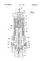
- FIG. 1is a side elevational view, in section, showing an improved connector in accord with the present invention.
- the present inventioncombines and improves on the advantages of a quartz spring biased high temperature connector in a new, novel connector which employs a ferrule forming screw to make an initial seal between a ferrule and a slightly undersize fluid conduit.
- An additional significant feature of the present inventionis a quick-lock adaptor that can be used with standard tubing fittings so that even a high temperature connection can be readily hooked up for various purposes such as with a gas chromatograph in a pyrolytic analysis system.
- Ferrule forming screw 92extends through cap end wall 16 and through the interior portion of cap 12 so that it is adjacent follower 56. If a slightly undersize conduit 70 with respect to ferrule 74 is used, then ferrule forming screw 92 can be used to create an initial seal with conduit end portion 72.
- ferrule forming screwhas a thread portion 90 which engages cap wall threaded bore 96. As ferrule forming screw head 94 is rotated, ferrule forming screw thrust surface 100 presses against follower thrust surface 102.
- follower cylindrical portion 58 and follower extended cylindrical portion 62Atransmit this pressure to boss 66.
- Ferrule 74is preferably made of a deformable material.
- deformablerefers to a material which, under compression, deforms to the extent necessary to achieve a gas-tight seal between the ferrule and the engaged surface or surfaces.
- This inventionshows tubing adaptor receiver 104 used to adapt connector 10 to conduit 40 by forming a quick-lock attachment to base 22A.
- Adaptor nozzle 108has threads 112 which mate to conduit threaded portion 110. It is understood that other connections could be made at this point such as a swage tubing fitting.
- Adaptor receiver portion 106accommodates base 22A.
- Base 22Ahas grooves 118 into which adaptor pins 114 project. Each groove 118 has a recessed portion 116 into which pins 114 lock.
- a high temperature biasing meansmay be provided to hold pin 114 into recessed portion 116.
- quartz compressing spring 54can be used for a dual purpose of not only providing sealing bias for ferrule 74 but can also be used as bias to hold pins 114 into recessed portions 116.
- connector 10is placed into adaptor receiver portion 106 so that openings in grooves 118 are lined up with locking pins 114. Subsequently a quick rotation of connector 10 places locking pins 114 in groove recessed portions 116. Locking pins 114 are locked into recessed portion 116 by the biasing force of quartz compression spring 54.
- Grooves 118may have been several shapes.
- grooves 188are L-shaped so that pins 114 first enter a portion of grooves 188 that is substantially parallel in direction to conduit 70. After reaching the corner of the L-shaped groove 118, the connector is given a twist and pins 114 move in a plane substantially perpendicular to conduit until reaching recessed portion 116.
- grooves 118could have other shapes including an inclined shape.
- pins 114could be attached to base 22A and grooves 118 located in adaptor receiver portion 106. Alternatively, other structures could be used for holding base 22A into adaptor receiver portion 106 including a swage connection.
- Adaptor receiver 104includes aperture 112 through which follower extended cylindrical portion 62A can transmit pressure to boss 66. Therefore, due to the construction of adaptor receiver 104, it is possible to make a quick-change connector that is useful even with large temperature changes, high temperatures and/or high pressures.
Landscapes
- Engineering & Computer Science (AREA)
- General Engineering & Computer Science (AREA)
- Mechanical Engineering (AREA)
- Quick-Acting Or Multi-Walled Pipe Joints (AREA)
Abstract
Description
Claims (11)
Priority Applications (2)
| Application Number | Priority Date | Filing Date | Title |
|---|---|---|---|
| US07/736,516US5163722A (en) | 1991-07-26 | 1991-07-26 | Connection apparatus with ferrule forming structure |
| GB9213841AGB2258897B (en) | 1991-07-26 | 1992-06-30 | Connection apparatus |
Applications Claiming Priority (1)
| Application Number | Priority Date | Filing Date | Title |
|---|---|---|---|
| US07/736,516US5163722A (en) | 1991-07-26 | 1991-07-26 | Connection apparatus with ferrule forming structure |
Publications (1)
| Publication Number | Publication Date |
|---|---|
| US5163722Atrue US5163722A (en) | 1992-11-17 |
Family
ID=24960175
Family Applications (1)
| Application Number | Title | Priority Date | Filing Date |
|---|---|---|---|
| US07/736,516Expired - LifetimeUS5163722A (en) | 1991-07-26 | 1991-07-26 | Connection apparatus with ferrule forming structure |
Country Status (2)
| Country | Link |
|---|---|
| US (1) | US5163722A (en) |
| GB (1) | GB2258897B (en) |
Cited By (37)
| Publication number | Priority date | Publication date | Assignee | Title |
|---|---|---|---|---|
| US5215340A (en)* | 1991-03-01 | 1993-06-01 | Icr Research Associates, Inc. | Capillary quick-connect |
| US5234235A (en)* | 1992-11-30 | 1993-08-10 | Ruska Laboratories, Inc. | Connection apparatus |
| US5288113A (en)* | 1992-12-24 | 1994-02-22 | Restek Corporation | Connector for capillary tubes having a tapered inner bore |
| EP0636882A1 (en)* | 1993-07-30 | 1995-02-01 | Microsensor Technology, Inc. | Connector for capillary tubes |
| US5533762A (en)* | 1993-07-09 | 1996-07-09 | Assistance Proto Industrie France | Assembly device of an element on a part presenting a fluid channel |
| US5540464A (en)* | 1994-10-04 | 1996-07-30 | J&W Scientific Incorporated | Capillary connector |
| US5595406A (en)* | 1995-11-30 | 1997-01-21 | Hewlett-Packard Co. | Capillary tubing connector |
| US6056331A (en)* | 1996-09-12 | 2000-05-02 | The Regents Of The University Of California | Zero dead volume tube to surface seal |
| US6102449A (en)* | 1998-10-29 | 2000-08-15 | Agilent Technologies, In. | Connector for capillary tubing |
| US6129361A (en)* | 1998-07-06 | 2000-10-10 | Ford Global Technologies, Inc. | Fluid conduit seal |
| US6193286B1 (en) | 1998-02-27 | 2001-02-27 | Selerity Technologies Inc. | Device and method for connecting a fluid conduit to a receiving fitting |
| US6418911B1 (en) | 2001-07-13 | 2002-07-16 | Siemens Diesel Systems Technology | Device and procedure for coupling a fluid rail with fuel injectors |
| US6494500B1 (en)* | 1999-05-12 | 2002-12-17 | Geoff Todosiev | Universal high pressure liquid connector |
| US6565128B2 (en) | 2001-07-13 | 2003-05-20 | Siemens Diesel Systems Technology | Device and method for coupling a fluid rail with fuel injectors |
| WO2005119110A2 (en) | 2004-05-28 | 2005-12-15 | New Objective, Inc. | Method and apparatus for connecting small diameter tubing |
| US7066496B2 (en) | 2001-02-06 | 2006-06-27 | Swagelok Company | Fitting with separable gripping device for pipe and tube |
| US7108288B2 (en) | 2001-02-06 | 2006-09-19 | Swagelok Company | Tube fitting with separable tube gripping ring |
| US20070158942A1 (en)* | 2004-03-02 | 2007-07-12 | Waters Investments Limited | Self-setting high pressure fitting |
| US7393018B2 (en) | 2001-02-06 | 2008-07-01 | Swagelok Company | Tube fitting for stainless steel tubing |
| US7407196B2 (en) | 2003-08-06 | 2008-08-05 | Swagelok Company | Tube fitting with separable tube gripping device |
| US7416225B2 (en) | 2001-02-06 | 2008-08-26 | Swagelok Company | Fitting for metal pipe and tubing |
| US7695027B2 (en) | 2004-04-22 | 2010-04-13 | Swagelok Company | Fitting for tube and pipe |
| US7784837B2 (en) | 2003-11-03 | 2010-08-31 | Swagelok Company | Fitting for metal pipe and tubing |
| US8038180B2 (en) | 2004-04-22 | 2011-10-18 | Swagelok Company | Fitting with taper and single ferrule |
| US20120153608A1 (en)* | 2010-12-21 | 2012-06-21 | Baker Hughes Incorporated | Wet disconnect system with post disconnection pressure integrity |
| WO2013032835A1 (en)* | 2011-08-26 | 2013-03-07 | Waters Technologies Corporation | Reusable fitting for attaching a conduit to a port |
| US20140053639A1 (en)* | 2011-04-25 | 2014-02-27 | Waters Technologies Corporation | Fitting Assemblies |
| US20140145437A1 (en)* | 2011-05-02 | 2014-05-29 | Dionex Softron Gmbh | Connector Unit and Connecting System for Connecting Capillaries, In Particular For High-Performance Liquid Chromatography |
| US20140375050A1 (en)* | 2012-02-01 | 2014-12-25 | Agilent Technologies, Inc. | Quick lock connector for connecting a capillary to a fluidic conduit of a fluidic component |
| US20150285414A1 (en)* | 2012-11-21 | 2015-10-08 | Hitachi High-Technologies Corporation | Pipe connection joint |
| CN104981690A (en)* | 2013-02-06 | 2015-10-14 | 安捷伦科技有限公司 | Fluidic coupling devices, assemblies, and related methods |
| US20170184225A1 (en)* | 2014-05-22 | 2017-06-29 | Shimadzu Corporation | Column-attaching device and ferrule set |
| US20170292641A1 (en)* | 2016-04-11 | 2017-10-12 | Micromass Uk Limited | Probe Assembly Connector |
| US10184921B2 (en) | 2015-08-07 | 2019-01-22 | Perkinelmer Health Sciences, Inc. | Gas chromatograph column connection device |
| JP2022001795A (en)* | 2016-06-13 | 2022-01-06 | アイデックス ヘルス アンド サイエンス エルエルシー | Fluid connection assembly for quick connection/disconnection |
| US11554330B2 (en) | 2017-12-12 | 2023-01-17 | Dionex Softron Gmbh | Plug units, particularly for HPLC, connection system and corresponding use |
| US20230029511A1 (en)* | 2021-07-27 | 2023-02-02 | Thermo Finnigan Llc | Compression Nut or Fitting with Removable Plunger for Easily Dislodging Stuck Ferrules |
Families Citing this family (1)
| Publication number | Priority date | Publication date | Assignee | Title |
|---|---|---|---|---|
| US10215315B2 (en) | 2008-09-05 | 2019-02-26 | Parker-Hannifin Corporation | Tube compression fitting and flared fitting used with connection body and method of making same |
Citations (13)
| Publication number | Priority date | Publication date | Assignee | Title |
|---|---|---|---|---|
| US820774A (en)* | 1905-08-30 | 1906-05-15 | Anders Gustav Flyberg | Pipe-coupling. |
| US951889A (en)* | 1909-10-12 | 1910-03-15 | William H Teuer | Pipe-coupling. |
| US966198A (en)* | 1908-04-13 | 1910-08-02 | James P Haig | Valve. |
| US1383127A (en)* | 1920-03-29 | 1921-06-28 | Henry P Kraft | Double pump connection |
| US1810115A (en)* | 1927-03-30 | 1931-06-16 | Schraders Son Inc | Air bag valve coupling |
| US1883283A (en)* | 1930-05-19 | 1932-10-18 | Alemite Corp | Lubricating apparatus |
| US1937865A (en)* | 1932-03-07 | 1933-12-05 | Wallace & Tiernan Company Inc | Glass-to-metal joint |
| US2129704A (en)* | 1934-05-17 | 1938-09-13 | Meyer Coupling Company Inc | Coupling with disconnecter |
| US2476777A (en)* | 1945-10-01 | 1949-07-19 | Smith Welding Equipment Corp | Combination welding and cutting torch |
| US4281679A (en)* | 1979-08-27 | 1981-08-04 | Stearns Stanley D | Flow control means for use in an adaptor assembly |
| US4669763A (en)* | 1984-12-19 | 1987-06-02 | Phillips Edwin D | Gripping saddle and O-ring apparatus |
| US4787656A (en)* | 1985-06-19 | 1988-11-29 | Hewlett-Packard Company | Capillary tubing coupler |
| US4991883A (en)* | 1989-09-25 | 1991-02-12 | Ruska Laboratories, Inc. | Connection apparatus |
- 1991
- 1991-07-26USUS07/736,516patent/US5163722A/ennot_activeExpired - Lifetime
- 1992
- 1992-06-30GBGB9213841Apatent/GB2258897B/ennot_activeExpired - Fee Related
Patent Citations (13)
| Publication number | Priority date | Publication date | Assignee | Title |
|---|---|---|---|---|
| US820774A (en)* | 1905-08-30 | 1906-05-15 | Anders Gustav Flyberg | Pipe-coupling. |
| US966198A (en)* | 1908-04-13 | 1910-08-02 | James P Haig | Valve. |
| US951889A (en)* | 1909-10-12 | 1910-03-15 | William H Teuer | Pipe-coupling. |
| US1383127A (en)* | 1920-03-29 | 1921-06-28 | Henry P Kraft | Double pump connection |
| US1810115A (en)* | 1927-03-30 | 1931-06-16 | Schraders Son Inc | Air bag valve coupling |
| US1883283A (en)* | 1930-05-19 | 1932-10-18 | Alemite Corp | Lubricating apparatus |
| US1937865A (en)* | 1932-03-07 | 1933-12-05 | Wallace & Tiernan Company Inc | Glass-to-metal joint |
| US2129704A (en)* | 1934-05-17 | 1938-09-13 | Meyer Coupling Company Inc | Coupling with disconnecter |
| US2476777A (en)* | 1945-10-01 | 1949-07-19 | Smith Welding Equipment Corp | Combination welding and cutting torch |
| US4281679A (en)* | 1979-08-27 | 1981-08-04 | Stearns Stanley D | Flow control means for use in an adaptor assembly |
| US4669763A (en)* | 1984-12-19 | 1987-06-02 | Phillips Edwin D | Gripping saddle and O-ring apparatus |
| US4787656A (en)* | 1985-06-19 | 1988-11-29 | Hewlett-Packard Company | Capillary tubing coupler |
| US4991883A (en)* | 1989-09-25 | 1991-02-12 | Ruska Laboratories, Inc. | Connection apparatus |
Cited By (61)
| Publication number | Priority date | Publication date | Assignee | Title |
|---|---|---|---|---|
| US5215340A (en)* | 1991-03-01 | 1993-06-01 | Icr Research Associates, Inc. | Capillary quick-connect |
| US5601785A (en)* | 1991-12-23 | 1997-02-11 | Microsensor Technology, Inc. | Connector for detachable column cartridge for gas chromatograph |
| US5578157A (en)* | 1991-12-23 | 1996-11-26 | Microsensor Technology, Inc. | Method of fabricating connector |
| US5234235A (en)* | 1992-11-30 | 1993-08-10 | Ruska Laboratories, Inc. | Connection apparatus |
| US5288113A (en)* | 1992-12-24 | 1994-02-22 | Restek Corporation | Connector for capillary tubes having a tapered inner bore |
| US5533762A (en)* | 1993-07-09 | 1996-07-09 | Assistance Proto Industrie France | Assembly device of an element on a part presenting a fluid channel |
| EP0636882A1 (en)* | 1993-07-30 | 1995-02-01 | Microsensor Technology, Inc. | Connector for capillary tubes |
| US5540464A (en)* | 1994-10-04 | 1996-07-30 | J&W Scientific Incorporated | Capillary connector |
| US5595406A (en)* | 1995-11-30 | 1997-01-21 | Hewlett-Packard Co. | Capillary tubing connector |
| US6056331A (en)* | 1996-09-12 | 2000-05-02 | The Regents Of The University Of California | Zero dead volume tube to surface seal |
| US6193286B1 (en) | 1998-02-27 | 2001-02-27 | Selerity Technologies Inc. | Device and method for connecting a fluid conduit to a receiving fitting |
| US6129361A (en)* | 1998-07-06 | 2000-10-10 | Ford Global Technologies, Inc. | Fluid conduit seal |
| US6102449A (en)* | 1998-10-29 | 2000-08-15 | Agilent Technologies, In. | Connector for capillary tubing |
| US6494500B1 (en)* | 1999-05-12 | 2002-12-17 | Geoff Todosiev | Universal high pressure liquid connector |
| US7815226B2 (en) | 2001-02-06 | 2010-10-19 | Swagelok Company | Fitting for metal pipe and tubing |
| US7416225B2 (en) | 2001-02-06 | 2008-08-26 | Swagelok Company | Fitting for metal pipe and tubing |
| US7762592B2 (en) | 2001-02-06 | 2010-07-27 | Swagelok Company | Tube fitting for stainless steel tubing |
| US7066496B2 (en) | 2001-02-06 | 2006-06-27 | Swagelok Company | Fitting with separable gripping device for pipe and tube |
| US7108288B2 (en) | 2001-02-06 | 2006-09-19 | Swagelok Company | Tube fitting with separable tube gripping ring |
| US7740283B2 (en) | 2001-02-06 | 2010-06-22 | Swagelok Company | Tube fitting with separable tube gripping device |
| US7677602B2 (en) | 2001-02-06 | 2010-03-16 | Swagelok Company | Tube fitting |
| US7393018B2 (en) | 2001-02-06 | 2008-07-01 | Swagelok Company | Tube fitting for stainless steel tubing |
| US6565128B2 (en) | 2001-07-13 | 2003-05-20 | Siemens Diesel Systems Technology | Device and method for coupling a fluid rail with fuel injectors |
| US6418911B1 (en) | 2001-07-13 | 2002-07-16 | Siemens Diesel Systems Technology | Device and procedure for coupling a fluid rail with fuel injectors |
| US7407196B2 (en) | 2003-08-06 | 2008-08-05 | Swagelok Company | Tube fitting with separable tube gripping device |
| US7784837B2 (en) | 2003-11-03 | 2010-08-31 | Swagelok Company | Fitting for metal pipe and tubing |
| US7735878B2 (en) | 2004-03-02 | 2010-06-15 | Waters Technologies Corporation | Self-setting high pressure fitting |
| US20070158942A1 (en)* | 2004-03-02 | 2007-07-12 | Waters Investments Limited | Self-setting high pressure fitting |
| US7695027B2 (en) | 2004-04-22 | 2010-04-13 | Swagelok Company | Fitting for tube and pipe |
| US8038180B2 (en) | 2004-04-22 | 2011-10-18 | Swagelok Company | Fitting with taper and single ferrule |
| WO2005119110A2 (en) | 2004-05-28 | 2005-12-15 | New Objective, Inc. | Method and apparatus for connecting small diameter tubing |
| US7681926B2 (en)* | 2004-05-28 | 2010-03-23 | New Objective, Inc. | Method and apparatus for connecting small diameter tubing |
| US20070164562A1 (en)* | 2004-05-28 | 2007-07-19 | New Objective, Inc. | Method and apparatus for connecting small diameter tubing |
| US20120153608A1 (en)* | 2010-12-21 | 2012-06-21 | Baker Hughes Incorporated | Wet disconnect system with post disconnection pressure integrity |
| US8459700B2 (en)* | 2010-12-21 | 2013-06-11 | Baker Hughes Incorporated | Wet disconnect system with post disconnection pressure integrity |
| US9618483B2 (en)* | 2011-04-25 | 2017-04-11 | Waters Technologies Corporation | Fitting assemblies |
| US20140053639A1 (en)* | 2011-04-25 | 2014-02-27 | Waters Technologies Corporation | Fitting Assemblies |
| US9804134B2 (en)* | 2011-05-02 | 2017-10-31 | Dionex Softron Gmbh | Connector unit and connecting system for connecting capillaries, in particular for high-performance liquid chromatography |
| US20140145437A1 (en)* | 2011-05-02 | 2014-05-29 | Dionex Softron Gmbh | Connector Unit and Connecting System for Connecting Capillaries, In Particular For High-Performance Liquid Chromatography |
| US10022736B2 (en) | 2011-08-26 | 2018-07-17 | Waters Technologies Corporation | Reusable fitting for attaching a conduit to a port |
| WO2013032835A1 (en)* | 2011-08-26 | 2013-03-07 | Waters Technologies Corporation | Reusable fitting for attaching a conduit to a port |
| CN103748396A (en)* | 2011-08-26 | 2014-04-23 | 沃特世科技公司 | Reusable fitting for attaching a conduit to a port |
| JP2014526054A (en)* | 2011-08-26 | 2014-10-02 | ウオーターズ・テクノロジーズ・コーポレイシヨン | Reusable fitting for attaching a conduit to a port |
| CN103748396B (en)* | 2011-08-26 | 2016-03-09 | 沃特世科技公司 | For pipeline being attached to the reusable accessory of port |
| US9784720B2 (en)* | 2012-02-01 | 2017-10-10 | Agilent Technologies, Inc. | Quick lock connector for connecting a capillary to a fluidic conduit of a fluidic component |
| US20140375050A1 (en)* | 2012-02-01 | 2014-12-25 | Agilent Technologies, Inc. | Quick lock connector for connecting a capillary to a fluidic conduit of a fluidic component |
| US11137378B2 (en) | 2012-02-01 | 2021-10-05 | Agilent Technologies, Inc. | Quick lock connector for connecting a capillary to a fluidic conduit of a fluidic component |
| US9470346B2 (en)* | 2012-11-21 | 2016-10-18 | Hitachi High-Technologies Corporation | Pipe connection joint |
| US20150285414A1 (en)* | 2012-11-21 | 2015-10-08 | Hitachi High-Technologies Corporation | Pipe connection joint |
| CN104981690A (en)* | 2013-02-06 | 2015-10-14 | 安捷伦科技有限公司 | Fluidic coupling devices, assemblies, and related methods |
| US10119638B2 (en) | 2013-02-06 | 2018-11-06 | Agilent Technologies, Inc. | Fluidic coupling devices, assemblies, and related methods |
| US10731779B2 (en)* | 2014-05-22 | 2020-08-04 | Shimadzu Corporation | Column-attaching device and ferrule set |
| US20170184225A1 (en)* | 2014-05-22 | 2017-06-29 | Shimadzu Corporation | Column-attaching device and ferrule set |
| US10184921B2 (en) | 2015-08-07 | 2019-01-22 | Perkinelmer Health Sciences, Inc. | Gas chromatograph column connection device |
| US20170292641A1 (en)* | 2016-04-11 | 2017-10-12 | Micromass Uk Limited | Probe Assembly Connector |
| US10438786B2 (en)* | 2016-04-11 | 2019-10-08 | Micromass Uk Limited | Probe assembly connector |
| JP2022001795A (en)* | 2016-06-13 | 2022-01-06 | アイデックス ヘルス アンド サイエンス エルエルシー | Fluid connection assembly for quick connection/disconnection |
| US11554330B2 (en) | 2017-12-12 | 2023-01-17 | Dionex Softron Gmbh | Plug units, particularly for HPLC, connection system and corresponding use |
| US20230029511A1 (en)* | 2021-07-27 | 2023-02-02 | Thermo Finnigan Llc | Compression Nut or Fitting with Removable Plunger for Easily Dislodging Stuck Ferrules |
| CN115681632A (en)* | 2021-07-27 | 2023-02-03 | 萨默费尼根有限公司 | Compression nut or fitting with removable plunger to ease removal of seized ferrule |
| US11767938B2 (en)* | 2021-07-27 | 2023-09-26 | Thermo Finnigan Llc | Compression nut or fitting with removable plunger for easily dislodging stuck ferrules |
Also Published As
| Publication number | Publication date |
|---|---|
| GB9213841D0 (en) | 1992-08-12 |
| GB2258897B (en) | 1995-05-17 |
| GB2258897A (en) | 1993-02-24 |
Similar Documents
| Publication | Publication Date | Title |
|---|---|---|
| US5163722A (en) | Connection apparatus with ferrule forming structure | |
| US4991883A (en) | Connection apparatus | |
| US5234235A (en) | Connection apparatus | |
| US3521910A (en) | Tube coupling | |
| US4619473A (en) | Fluid passage connector for liquid chromatograph | |
| US9945501B2 (en) | Plug unit and connection system for connecting capillary tubes | |
| CA1313211C (en) | Quick disconnect for aerosol spray can | |
| US4645246A (en) | Tube couplers | |
| US5669637A (en) | Miniature fitting assembly for micro-tubing | |
| US4876005A (en) | High pressure column assembly for a liquid chromatograph system | |
| US20080309076A1 (en) | Device and Method for a Fluid-Tight Connection | |
| JP7362735B2 (en) | Fitting assemblies for fluid connections | |
| JPH0325677B2 (en) | ||
| AU642898B2 (en) | Means for hose clamp replacement | |
| US20030015679A1 (en) | Access port (suitable for fluid/refrigerant system) | |
| US11493156B2 (en) | Hammerless and torqueless union connection | |
| US8491017B2 (en) | Fitting structure including a pair of connection pipes and a clamp ring | |
| JP2014513299A (en) | Fixture assembly | |
| US5573285A (en) | High-temperature, double-bead, tube-fitting assembly | |
| US10883633B2 (en) | Zero dead volume fitting assembly | |
| US4458927A (en) | Ferrules seals | |
| US5141262A (en) | Means of lowering the operational temperature for elastomeric seals | |
| US20240393299A1 (en) | Insertion sealing device for a chromatography column | |
| US5443580A (en) | Compact fitting | |
| EP0328146B1 (en) | A high pressure column assembly for a liquid chromatograph system |
Legal Events
| Date | Code | Title | Description |
|---|---|---|---|
| AS | Assignment | Owner name:RUSK LABORATORIES, INC., TEXAS Free format text:ASSIGNMENT OF ASSIGNORS INTEREST.;ASSIGNOR:WORDEN, RAYMOND D.;REEL/FRAME:005796/0203 Effective date:19910715 | |
| STCF | Information on status: patent grant | Free format text:PATENTED CASE | |
| AS | Assignment | Owner name:RUSKA INSTRUMENT CORPORATION, TEXAS Free format text:MERGER;ASSIGNORS:RUSKA LABORATORIES, INC.;RUSKA REALTY INCOROPRATED;RUSKA INTERNATIONAL EXPORT, INC.;REEL/FRAME:007439/0152 Effective date:19931231 | |
| FPAY | Fee payment | Year of fee payment:4 | |
| AS | Assignment | Owner name:LECO CORPORATION, MICHIGAN Free format text:ASSIGNMENT OF ASSIGNORS INTEREST;ASSIGNOR:RUSKA INSTRUMENT CORPORATION;REEL/FRAME:008559/0428 Effective date:19970520 | |
| FEPP | Fee payment procedure | Free format text:PAT HLDR NO LONGER CLAIMS SMALL ENT STAT AS SMALL BUSINESS (ORIGINAL EVENT CODE: LSM2); ENTITY STATUS OF PATENT OWNER: LARGE ENTITY | |
| FPAY | Fee payment | Year of fee payment:8 | |
| FPAY | Fee payment | Year of fee payment:12 |