US5161838A - Locking assembly - Google Patents
Locking assemblyDownload PDFInfo
- Publication number
- US5161838A US5161838AUS07/794,873US79487391AUS5161838AUS 5161838 AUS5161838 AUS 5161838AUS 79487391 AUS79487391 AUS 79487391AUS 5161838 AUS5161838 AUS 5161838A
- Authority
- US
- United States
- Prior art keywords
- shank
- stud
- collar
- housing member
- shank portion
- Prior art date
- Legal status (The legal status is an assumption and is not a legal conclusion. Google has not performed a legal analysis and makes no representation as to the accuracy of the status listed.)
- Expired - Lifetime
Links
- 230000006378damageEffects0.000description5
- 238000010276constructionMethods0.000description2
- 239000011521glassSubstances0.000description2
- 208000002991Ring chromosome 4 syndromeDiseases0.000description1
- 230000009286beneficial effectEffects0.000description1
- 230000014759maintenance of locationEffects0.000description1
- 239000002184metalSubstances0.000description1
- 230000004048modificationEffects0.000description1
- 238000012986modificationMethods0.000description1
- 230000000717retained effectEffects0.000description1
Images


Classifications
- G—PHYSICS
- G09—EDUCATION; CRYPTOGRAPHY; DISPLAY; ADVERTISING; SEALS
- G09F—DISPLAYING; ADVERTISING; SIGNS; LABELS OR NAME-PLATES; SEALS
- G09F3/00—Labels, tag tickets, or similar identification or indication means; Seals; Postage or like stamps
- G09F3/02—Forms or constructions
- G09F3/03—Forms or constructions of security seals
- G09F3/0305—Forms or constructions of security seals characterised by the type of seal used
- G09F3/0317—Forms or constructions of security seals characterised by the type of seal used having bolt like sealing means
- F—MECHANICAL ENGINEERING; LIGHTING; HEATING; WEAPONS; BLASTING
- F16—ENGINEERING ELEMENTS AND UNITS; GENERAL MEASURES FOR PRODUCING AND MAINTAINING EFFECTIVE FUNCTIONING OF MACHINES OR INSTALLATIONS; THERMAL INSULATION IN GENERAL
- F16B—DEVICES FOR FASTENING OR SECURING CONSTRUCTIONAL ELEMENTS OR MACHINE PARTS TOGETHER, e.g. NAILS, BOLTS, CIRCLIPS, CLAMPS, CLIPS OR WEDGES; JOINTS OR JOINTING
- F16B21/00—Means for preventing relative axial movement of a pin, spigot, shaft or the like and a member surrounding it; Stud-and-socket releasable fastenings
- F16B21/10—Means for preventing relative axial movement of a pin, spigot, shaft or the like and a member surrounding it; Stud-and-socket releasable fastenings by separate parts
- F16B21/16—Means for preventing relative axial movement of a pin, spigot, shaft or the like and a member surrounding it; Stud-and-socket releasable fastenings by separate parts with grooves or notches in the pin or shaft
- F16B21/18—Means for preventing relative axial movement of a pin, spigot, shaft or the like and a member surrounding it; Stud-and-socket releasable fastenings by separate parts with grooves or notches in the pin or shaft with circlips or like resilient retaining devices, i.e. resilient in the plane of the ring or the like; Details
- F16B21/186—Means for preventing relative axial movement of a pin, spigot, shaft or the like and a member surrounding it; Stud-and-socket releasable fastenings by separate parts with grooves or notches in the pin or shaft with circlips or like resilient retaining devices, i.e. resilient in the plane of the ring or the like; Details external, i.e. with contracting action
- G—PHYSICS
- G09—EDUCATION; CRYPTOGRAPHY; DISPLAY; ADVERTISING; SEALS
- G09F—DISPLAYING; ADVERTISING; SIGNS; LABELS OR NAME-PLATES; SEALS
- G09F3/00—Labels, tag tickets, or similar identification or indication means; Seals; Postage or like stamps
- G09F3/02—Forms or constructions
- G09F3/03—Forms or constructions of security seals
- G09F3/0382—Seals with transparent casing
- Y—GENERAL TAGGING OF NEW TECHNOLOGICAL DEVELOPMENTS; GENERAL TAGGING OF CROSS-SECTIONAL TECHNOLOGIES SPANNING OVER SEVERAL SECTIONS OF THE IPC; TECHNICAL SUBJECTS COVERED BY FORMER USPC CROSS-REFERENCE ART COLLECTIONS [XRACs] AND DIGESTS
- Y10—TECHNICAL SUBJECTS COVERED BY FORMER USPC
- Y10T—TECHNICAL SUBJECTS COVERED BY FORMER US CLASSIFICATION
- Y10T292/00—Closure fasteners
- Y10T292/51—Seal bolts
Definitions
- the inventionrelates to locking devices and is directed more particularly to a destructible locking assembly for use in conjunction with utility meter ring members, gas service valves, and similar devices.
- a cover memberoften of transparent glass, be placed over the face of the meter and secured to a meter box by a metal ring.
- the ringincludes two flanges which extend outwardly from the ring substantially parallel to each other.
- the flangesare provided with holes enabling an operator to place a padlock through the holes for locking the flanges together to fix the ring to the meter, thereby locking in place the glass cover.
- a locking devicewhich could not be opened by a key and which would provide a readily visible sign of having been tampered with, would be beneficial to the utility industry.
- an object of the inventionto provide a locking assembly for a utility meter, the locking assembly being such as to require destruction of a portion thereof, which destruction is readily apparent.
- a further object of the inventionis to provide as a portion of a locking assembly a locking device which is frangible and which, once opened by destruction thereof, is not adaptable to being returned to its normal appearance.
- a still further object of the inventionis to provide a locking device which is frangible and which is of such low cost as to render routine destruction thereof to gain legitimate access to the protected meter an acceptable cost.
- a feature of the present inventionis the provision of a locking device adapted for locking first and second members together, the device comprising a housing member and a stud member, the housing member having a body portion and a flange portion, the body portion having a cavity therein, the stud member comprising a shaft portion and a collar portion, the housing member body portion cavity being adapted to receive the stud member shaft portion and permanently lock the stud member shaft portion in the housing member body portion cavity with the first and second members disposed between the housing member flange portion and the stud member collar portion, the device having a frangible portion, whereby a part of the device is adapted to be broken away from a remainder of the device to facilitate removal of the device from the first and second members.
- a utility meter locking assemblycomprising a ring member having first and second ends, a first flange extending from the first end of the ring member and a second flange extending from the second end of the ring member, the two flanges extending outwardly from the ring member and generally parallel to each other, a locking device for locking the first and second flanges together, the locking device comprising a stud member and a housing member adapted to be permanently interengaged, and tool means adapted to release the flanges from each other by deformation of the locking device.
- FIG. 1is an exploded elevational view of one form of locking assembly illustrative of an embodiment of the invention
- FIG. 2is an exploded centerline sectional view of the locking assembly shown in FIG. 1;
- FIG. 3is a sectional view of the locking assembly, similar to FIG. 2, but showing the assembly components joined together;
- FIG. 4is a plan view of a locking ring member for a utility meter locking assembly in combination with the locking assembly of FIGS. 1-3;
- FIG. 5is a front elevational view of the locking ring member and locking assembly shown in FIG. 4;
- FIG. 6is a perspective view of a utility meter with the combination of locking ring member and locking assembly of FIGS. 4 and 5 thereon;
- FIG. 7is a sectional view of the locking assembly shown in FIG. 3, but showing the assembly in its broken and releasable condition;
- FIG. 8is an elevational view of a tool used to break and release the locking assembly
- FIG. 9is a perspective view of a gas service valve of the type with which the invention finds utility.
- FIG. 10is a side elevational view of the gas service valve of FIG. 9, shown with a locking assembly illustrative of an alternative embodiment of housing member;
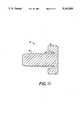
- FIG. 11is a side elevational view of an alternative embodiment of stud member.
- a locking deviceillustrative of the invention includes a housing member 2 having a body portion 4 and a flange portion 6.
- the body portion 4has a cavity 8 therein defined by an inside wall 10.
- the inside wall 10is provided with a circular groove 12 which retains a snap ring 14.
- the circular groove 12has an inclined wall 16. A larger diameter of the circular groove 12 is on a side 18 of the circular groove closer to the flange portion 6, and a smaller diameter of the circular groove is on a side 20 of the circular groove further from the flange portion 6. Accordingly, when the snap ring 14 is urged in a direction away from the flange portion 6, or towards an opening 22 of the cavity 8, the snap ring is urged inwardly of the cavity 8 by the circular groove inclined wall 16.
- the locking assemblyfurther includes a stud member 30 having a shank portion 32 and a collar portion 34.
- the collar portion 34includes a collar member 36 having an annular recess 38 therein adjacent a central opening 40 therethrough.
- the collar portion 34further includes a head portion 42 of the shank portion 32, which head portion 42 is disposed at one end of the shank portion 32, extends through the collar member central opening 40, and is disposed in the annular recess 38 of the collar member 36.
- the shank portion 32is provided with at least one circumferential groove 44 (three such grooves are illustrated in the drawings) adapted to receive the snap ring 14 disposed in the housing member body portion cavity 8.
- the locking deviceis provided with a frangible portion, such that a portion of the device is adapted to be broken away from a remainder of the device.
- the stud member 30is provided with a frangible portion 50.
- the head portion 42 of the shank portion 32is provided with groove means 52 at the juncture of the shank portion 32 and the head portion 42.
- the head portion 42may be further provided with a recess 54 adapted to receive a pressure-applying tool for breaking the frangible portion 50 of the stud member 30.
- the above-described locking devicemay be used in conjunction with a ring member 60 adapted to fit about a utility meter cover portion M and lock the cover portion M to a meter box B.
- the ring member 60is provided with first and second ends 62, 64, with a first flange 66 extending from the first ring member end 62 and a second flange 68 extending from the second ring member end 64.
- the first and second flanges 66, 68extend outwardly from the ring member 60 and generally parallel to each other.
- the first and second flanges 66, 68are, respectively, provided with holes 70, 72 extending therethrough, the holes 70, 72 being readily alignable to receive the above-described locking assembly.
- the housing member body portion 4is inserted into the first flange hole 70 and the stud member shank portion 32 is inserted through the second flange hole 72 and into the housing member cavity 8.
- the snap ring 14partially enters a circumferential groove 44 to lock the stud member 30 to the housing member 2, with the ring member first and second flanges 66, 68 disposed between the housing member flange portion 6 and the stud member collar portion 34.
- the circumferential groove 44includes a first wall portion 80 generally normal to the outside wall of the shank portion 32, and a second wall portion 82 sloping to the outside wall of the shank portion, with the first wall portion 80 being closer to a distal end 84 of the shank portion 32, and the second wall portion 82 being further from the distal end 84 of the shank portion, such that the snap ring -4 is adapted to move out of the circumferential groove 44 by sliding along the second wall portion 82, but is restrained from moving out of the circumferential groove when engaged by the first wall portion 80.
- the shank portion 32easily may be pushed further into the cavity 8, but cannot be withdrawn from the cavity once the snap ring 14 has engaged the circumferential groove.
- the shank portion 32is provided with a plurality of circumferential grooves 44 (three shown in the drawings) such that the snap ring 14 may settle in the circumferential groove permitting the most snug fitting of the flange portion 6 and the collar portion 34 about the ring member flanges 66, 68.
- the two members 2, 30may be urged closer together, but cannot be pulled apart.
- An attempt to pull the members 2, 30 apartresults in the snap ring being urged by the inclined wall 16 inwardly of the shank portion 32, more firmly locking the two members together.
- a pressure-applying tool 90adapted to break the frangible portion 50 of the stud member 30, whereby to release the ring member flanges 66, 68 to permit removal of the ring member 60.
- the tool 90includes first and second arms 92, 94 extending from a handle portion 95, and a plunger member 96 mounted in the first arm 92 and movable toward the second arm 94.
- the stud member recess 54is adapted to receive an end 97 of the plunger member 96 while the locking device is disposed between the tool means second arm 94 and the plunger end 97.
- Movement of the plunger member 96 toward the second arm 94is operative to break the frangible portion 50 of the stud member, separating the collar portion 34 from the shank portion 32 and permitting withdrawal of the housing member 2 and shank portion 32 from the ring member flanges 66, 68.
- One end 98 of the plunger member 96may be provided with means, such as a socket 99, for receiving a wrench or power tool means (not shown) suitable for threadedly turning, or otherwise axially moving the plunger member 96 to cause its axial movement against the stud member head portion 42 to cause breakage at the stud member frangible portion 50.
- the locking deviceTo gain access to the meter, the locking device must be deformed and, once deformed, such deformation is permanent and quite observable.
- the shank portion 32 of the stud member 30is provided with three of the circumferential grooves 44, two of the grooves 46 being available to interconnect the stud member 30 and the housing member 2, and a third groove 48 being used for retention of the shank portion 32 deep in the housing cavity 8 after the shank portion's having been forced deeply into the cavity by the operation of the tool 90. With the shank portion 32 retained deeply within the housing cavity 8, reattachment of the broken away parts to the shank portion is rendered most difficult.
- FIG. 10illustrates use of the inventive locking assembly with a gas service valve 100 in which the valve is opened by rotation of a first flange member 102 relative to a second flange member 104.
- the two flangesare provided with holes 106, 108, respectively, extending therethrough and readily alignable to receive the above-described locking assembly.
- FIG. 10further illustrates an alternative embodiment of housing member 2' having a body portion 4' which itself is larger in diameter than the hole 108 and therefore serves as a flange in that the body portion 4' is adapted to bear against a surface 110 of the flange member 104.
- FIG. 11there is disclosed an alternative embodiment of stud member 30' in which the shank portion 32' and the collar portion 34' are integral.
- Frangible portions 50'facilitate breaking apart of the shank and collar portions 32', 34' from each other.
Landscapes
- Engineering & Computer Science (AREA)
- General Engineering & Computer Science (AREA)
- Computer Security & Cryptography (AREA)
- Physics & Mathematics (AREA)
- General Physics & Mathematics (AREA)
- Theoretical Computer Science (AREA)
- Mechanical Engineering (AREA)
- Snaps, Bayonet Connections, Set Pins, And Snap Rings (AREA)
Abstract
Description
Claims (9)
Priority Applications (1)
| Application Number | Priority Date | Filing Date | Title |
|---|---|---|---|
| US07/794,873US5161838A (en) | 1991-11-19 | 1991-11-19 | Locking assembly |
Applications Claiming Priority (1)
| Application Number | Priority Date | Filing Date | Title |
|---|---|---|---|
| US07/794,873US5161838A (en) | 1991-11-19 | 1991-11-19 | Locking assembly |
Publications (1)
| Publication Number | Publication Date |
|---|---|
| US5161838Atrue US5161838A (en) | 1992-11-10 |
Family
ID=25163942
Family Applications (1)
| Application Number | Title | Priority Date | Filing Date |
|---|---|---|---|
| US07/794,873Expired - LifetimeUS5161838A (en) | 1991-11-19 | 1991-11-19 | Locking assembly |
Country Status (1)
| Country | Link |
|---|---|
| US (1) | US5161838A (en) |
Cited By (43)
| Publication number | Priority date | Publication date | Assignee | Title |
|---|---|---|---|---|
| FR2711750A1 (en)* | 1993-10-28 | 1995-05-05 | Fii | Device for immobilising a body in a bore |
| DE4401530A1 (en)* | 1994-01-20 | 1995-07-27 | Schaeffler Waelzlager Kg | Valve seat plate with component fixture |
| US5443721A (en)* | 1994-02-10 | 1995-08-22 | Basf Corporation | Filter cartridge mounting assembly |
| GB2286867A (en)* | 1994-02-23 | 1995-08-30 | Peter Joseph Langdon | Eyelet or plug for fitting to sheet material |
| US5582447A (en)* | 1995-02-24 | 1996-12-10 | E. J. Brooks Company | Locking device with serpentine gripping member |
| US6139638A (en)* | 1998-01-27 | 2000-10-31 | Thermo Web Systems, Inc. | Fluid assisted doctor |
| USD454773S1 (en) | 2001-08-27 | 2002-03-26 | Transguard Industries, Inc. | Bolt with oval head |
| EP1088998A3 (en)* | 1999-09-29 | 2002-06-12 | HILTI Aktiengesellschaft | Quick fastener for a threaded shaft |
| US6406074B1 (en) | 1999-11-10 | 2002-06-18 | Inner-Tite Corp. | Destructible locking device |
| USD462600S1 (en) | 2001-08-27 | 2002-09-10 | Transguard Industries, Inc. | Bolt with round head |
| US6550829B1 (en)* | 2000-02-09 | 2003-04-22 | Dobson Dewayne L. | Cargo security seal |
| US6677742B1 (en) | 1999-09-24 | 2004-01-13 | Landis+Gyr Inc. | Utility meter having a security sealing arrangement |
| US20040160067A1 (en)* | 2003-02-13 | 2004-08-19 | Ely Timothy B. | Tamper evident locking assembly |
| FR2851366A1 (en)* | 2003-02-19 | 2004-08-20 | Cogema Logistics | Temporary lock, for lifting lug on radioactive waste container, has plates with interlocking male and female components that are broken to remove it |
| US20060090525A1 (en)* | 2004-11-03 | 2006-05-04 | Mattson David O | Tamper resistant lock |
| US20060267355A1 (en)* | 2005-05-31 | 2006-11-30 | Stachowiak John E Jr | Locking apparatus and method |
| US20070200365A1 (en)* | 2005-05-31 | 2007-08-30 | Stachowiak John E Jr | Locking apparatus and method |
| ES2294970A1 (en)* | 2007-08-02 | 2008-04-01 | Emilio Layrana Fernandez | Security seal |
| US20080143123A1 (en)* | 2005-05-31 | 2008-06-19 | Dewalch Norman Binz | Locking apparatus and method |
| US20080238111A1 (en)* | 2004-05-25 | 2008-10-02 | Zachary Leroy Davidson | Apparatus and method for securing a watthour electrical meter to a socket box |
| US20080264117A1 (en)* | 2005-05-31 | 2008-10-30 | Dewalch Norman Binz | Locking apparatus and method |
| US20080290670A1 (en)* | 2005-05-31 | 2008-11-27 | Dewalch Norman Binz | Sealing system and method |
| US20090185853A1 (en)* | 2006-01-20 | 2009-07-23 | Fred Koelling | Releasable locking mechanism |
| US20090199375A1 (en)* | 2006-01-20 | 2009-08-13 | Fred Koelling | Latching system |
| US20090264012A1 (en)* | 2006-04-04 | 2009-10-22 | Stachowiak Jr John Edward | Securing apparatus and method |
| US20100000270A1 (en)* | 2007-01-25 | 2010-01-07 | Dewalch Norman Binz | Locking apparatus and method |
| US20100217274A1 (en)* | 2005-04-15 | 2010-08-26 | Abbott Medical Optics Inc. | Multi-action device for inserting an intraocular lens into an eye |
| US20100295255A1 (en)* | 2005-05-31 | 2010-11-25 | Dewalch Norman Binz | Retaining apparatus for a seal |
| US20110142531A1 (en)* | 2005-05-31 | 2011-06-16 | Dewalch Norman Binz | Sealing System and Method |
| US20110206449A1 (en)* | 2005-06-03 | 2011-08-25 | Dewalch Technologies, Inc. | Retained Lock System and Method |
| US20110204656A1 (en)* | 2009-01-27 | 2011-08-25 | Simon Lai | Electronic Seal |
| US20110217110A1 (en)* | 2008-10-29 | 2011-09-08 | Fabien Argillier | Detachable linking system for two components |
| JP2011527409A (en)* | 2008-07-07 | 2011-10-27 | フィン・クイバー・インコーポレイテッド | Detachable fixing mechanism |
| US20120134742A1 (en)* | 2010-11-30 | 2012-05-31 | Bal Seal Engineering, Inc. | Multi-stage engagement assemblies and related methods |
| US20130247624A1 (en)* | 2005-05-31 | 2013-09-26 | Norman Binz DeWalch | Bolt sealing apparatus and method |
| US20140179148A1 (en)* | 2012-12-21 | 2014-06-26 | Bal Seal Engineering, Inc. | Locking connectors and related methods |
| US20150027176A1 (en)* | 2013-07-29 | 2015-01-29 | Dewalch Technologies, Inc. | Securing Apparatus, System and Method |
| US20150259190A1 (en)* | 2012-10-08 | 2015-09-17 | Andrea Scianaro | Anti-theft device for a saddle |
| US20160217877A1 (en)* | 2013-08-23 | 2016-07-28 | The European Atomic Energy Community (Euratom), Represented By The European Commission | Sealing bolt and sealing system |
| US9464415B2 (en) | 2014-11-26 | 2016-10-11 | Kohler Co. | Faucet |
| US10414603B2 (en) | 2017-06-19 | 2019-09-17 | Cnh Industrial Canada, Ltd. | Connector for an agricultural vehicle |
| US20200321729A1 (en)* | 2017-12-14 | 2020-10-08 | Harting Electric Gmbh & Co. Kg | Plug-in connector |
| US10823761B2 (en) | 2006-04-04 | 2020-11-03 | Dewalch Technologies, Inc. | Securing apparatus and method |
Citations (11)
| Publication number | Priority date | Publication date | Assignee | Title |
|---|---|---|---|---|
| US393688A (en)* | 1888-11-27 | bbooks | ||
| US2319753A (en)* | 1940-07-05 | 1943-05-18 | Thomas F Smith | Lock |
| CH263455A (en)* | 1948-04-06 | 1949-08-31 | Fellmann Jos | Safety bolt. |
| US3867822A (en)* | 1973-08-02 | 1975-02-25 | Lynn H Morse | Locking means for electric meters |
| US3980337A (en)* | 1972-12-07 | 1976-09-14 | E. J. Brooks Company | Locking seal |
| US4225165A (en)* | 1979-06-19 | 1980-09-30 | Kesselman David A | Tamper-resistant fastener for utility meters |
| US4280726A (en)* | 1978-05-17 | 1981-07-28 | Aardee Spring & Lock Company Limited | Keyless lockable security devices |
| US4802700A (en)* | 1987-11-09 | 1989-02-07 | Trans-Guard Industries, Inc. | Locking seal |
| US4802699A (en)* | 1988-06-06 | 1989-02-07 | Brammall, Inc. | Snap lock assembly |
| US4936612A (en)* | 1989-10-24 | 1990-06-26 | Kohn Raymond F | One-piece single engagement seal lock |
| US5005883A (en)* | 1990-05-24 | 1991-04-09 | E. J. Brooks Company | Tamper indicator for a locking seal |
- 1991
- 1991-11-19USUS07/794,873patent/US5161838A/ennot_activeExpired - Lifetime
Patent Citations (12)
| Publication number | Priority date | Publication date | Assignee | Title |
|---|---|---|---|---|
| US393688A (en)* | 1888-11-27 | bbooks | ||
| US2319753A (en)* | 1940-07-05 | 1943-05-18 | Thomas F Smith | Lock |
| CH263455A (en)* | 1948-04-06 | 1949-08-31 | Fellmann Jos | Safety bolt. |
| US3980337A (en)* | 1972-12-07 | 1976-09-14 | E. J. Brooks Company | Locking seal |
| US3867822A (en)* | 1973-08-02 | 1975-02-25 | Lynn H Morse | Locking means for electric meters |
| US4280726A (en)* | 1978-05-17 | 1981-07-28 | Aardee Spring & Lock Company Limited | Keyless lockable security devices |
| US4225165A (en)* | 1979-06-19 | 1980-09-30 | Kesselman David A | Tamper-resistant fastener for utility meters |
| US4802700A (en)* | 1987-11-09 | 1989-02-07 | Trans-Guard Industries, Inc. | Locking seal |
| US4802700B1 (en)* | 1987-11-09 | 1996-10-01 | Transguard Ind Inc | Locking seal |
| US4802699A (en)* | 1988-06-06 | 1989-02-07 | Brammall, Inc. | Snap lock assembly |
| US4936612A (en)* | 1989-10-24 | 1990-06-26 | Kohn Raymond F | One-piece single engagement seal lock |
| US5005883A (en)* | 1990-05-24 | 1991-04-09 | E. J. Brooks Company | Tamper indicator for a locking seal |
Cited By (67)
| Publication number | Priority date | Publication date | Assignee | Title |
|---|---|---|---|---|
| FR2711750A1 (en)* | 1993-10-28 | 1995-05-05 | Fii | Device for immobilising a body in a bore |
| DE4401530A1 (en)* | 1994-01-20 | 1995-07-27 | Schaeffler Waelzlager Kg | Valve seat plate with component fixture |
| DE4401530B4 (en)* | 1994-01-20 | 2006-02-09 | Ina-Schaeffler Kg | Extruded snap |
| US5443721A (en)* | 1994-02-10 | 1995-08-22 | Basf Corporation | Filter cartridge mounting assembly |
| GB2286867A (en)* | 1994-02-23 | 1995-08-30 | Peter Joseph Langdon | Eyelet or plug for fitting to sheet material |
| GB2286867B (en)* | 1994-02-23 | 1997-07-02 | Peter Joseph Langdon | Eyelet |
| US5582447A (en)* | 1995-02-24 | 1996-12-10 | E. J. Brooks Company | Locking device with serpentine gripping member |
| US6139638A (en)* | 1998-01-27 | 2000-10-31 | Thermo Web Systems, Inc. | Fluid assisted doctor |
| US6677742B1 (en) | 1999-09-24 | 2004-01-13 | Landis+Gyr Inc. | Utility meter having a security sealing arrangement |
| EP1088998A3 (en)* | 1999-09-29 | 2002-06-12 | HILTI Aktiengesellschaft | Quick fastener for a threaded shaft |
| US6406074B1 (en) | 1999-11-10 | 2002-06-18 | Inner-Tite Corp. | Destructible locking device |
| US6550829B1 (en)* | 2000-02-09 | 2003-04-22 | Dobson Dewayne L. | Cargo security seal |
| USD454773S1 (en) | 2001-08-27 | 2002-03-26 | Transguard Industries, Inc. | Bolt with oval head |
| USD462600S1 (en) | 2001-08-27 | 2002-09-10 | Transguard Industries, Inc. | Bolt with round head |
| US20040160067A1 (en)* | 2003-02-13 | 2004-08-19 | Ely Timothy B. | Tamper evident locking assembly |
| FR2851366A1 (en)* | 2003-02-19 | 2004-08-20 | Cogema Logistics | Temporary lock, for lifting lug on radioactive waste container, has plates with interlocking male and female components that are broken to remove it |
| US20240085460A1 (en)* | 2004-05-25 | 2024-03-14 | Dewalch Technologies, Inc. | Apparatus and Method for Securing a Watthour Electrical Meter to a Socket Box |
| US20210255220A1 (en)* | 2004-05-25 | 2021-08-19 | Dewalch Technologies, Inc. | Apparatus and Method for Securing a Watthour Electrical Meter to a Socket Box |
| US20110253860A1 (en)* | 2004-05-25 | 2011-10-20 | Dewalch Technologies, Inc. | Apparatus and Method for Securing a Watthour Electrical Meter to a Socket Box |
| US20080238111A1 (en)* | 2004-05-25 | 2008-10-02 | Zachary Leroy Davidson | Apparatus and method for securing a watthour electrical meter to a socket box |
| US20060090525A1 (en)* | 2004-11-03 | 2006-05-04 | Mattson David O | Tamper resistant lock |
| US8926628B2 (en)* | 2005-04-15 | 2015-01-06 | Abbott Medical Optics Inc. | Multi-action device for inserting an intraocular lens into an eye |
| US20100217274A1 (en)* | 2005-04-15 | 2010-08-26 | Abbott Medical Optics Inc. | Multi-action device for inserting an intraocular lens into an eye |
| US20100295255A1 (en)* | 2005-05-31 | 2010-11-25 | Dewalch Norman Binz | Retaining apparatus for a seal |
| US20110142531A1 (en)* | 2005-05-31 | 2011-06-16 | Dewalch Norman Binz | Sealing System and Method |
| US20070200365A1 (en)* | 2005-05-31 | 2007-08-30 | Stachowiak John E Jr | Locking apparatus and method |
| US20090126425A1 (en)* | 2005-05-31 | 2009-05-21 | Dewalch Technologies, Inc. | Locking apparatus and method |
| US20130247624A1 (en)* | 2005-05-31 | 2013-09-26 | Norman Binz DeWalch | Bolt sealing apparatus and method |
| US20060267355A1 (en)* | 2005-05-31 | 2006-11-30 | Stachowiak John E Jr | Locking apparatus and method |
| US20080143123A1 (en)* | 2005-05-31 | 2008-06-19 | Dewalch Norman Binz | Locking apparatus and method |
| US20080290670A1 (en)* | 2005-05-31 | 2008-11-27 | Dewalch Norman Binz | Sealing system and method |
| US20080264117A1 (en)* | 2005-05-31 | 2008-10-30 | Dewalch Norman Binz | Locking apparatus and method |
| US20110206449A1 (en)* | 2005-06-03 | 2011-08-25 | Dewalch Technologies, Inc. | Retained Lock System and Method |
| US20090199375A1 (en)* | 2006-01-20 | 2009-08-13 | Fred Koelling | Latching system |
| US9090318B2 (en) | 2006-01-20 | 2015-07-28 | Lockdowel, Inc. | Latching system |
| US20090185853A1 (en)* | 2006-01-20 | 2009-07-23 | Fred Koelling | Releasable locking mechanism |
| US20150285284A1 (en)* | 2006-01-20 | 2015-10-08 | Lockdowel, Inc. | Latching System |
| US10202993B2 (en)* | 2006-01-20 | 2019-02-12 | Lockdowel, Inc. | Latching system |
| US10598699B2 (en) | 2006-04-04 | 2020-03-24 | Dewalch Technologies, Inc. | Securing apparatus and method |
| US20090264012A1 (en)* | 2006-04-04 | 2009-10-22 | Stachowiak Jr John Edward | Securing apparatus and method |
| US10823761B2 (en) | 2006-04-04 | 2020-11-03 | Dewalch Technologies, Inc. | Securing apparatus and method |
| US20100000270A1 (en)* | 2007-01-25 | 2010-01-07 | Dewalch Norman Binz | Locking apparatus and method |
| WO2009029124A1 (en)* | 2007-01-25 | 2009-03-05 | Dewalch Technologies, Inc. | Locking apparatus and method |
| ES2294970A1 (en)* | 2007-08-02 | 2008-04-01 | Emilio Layrana Fernandez | Security seal |
| ES2294970B1 (en)* | 2007-08-02 | 2009-05-01 | Emilio Layrana Fernandez | SECURITY SEAL. |
| JP2011527409A (en)* | 2008-07-07 | 2011-10-27 | フィン・クイバー・インコーポレイテッド | Detachable fixing mechanism |
| US20110217110A1 (en)* | 2008-10-29 | 2011-09-08 | Fabien Argillier | Detachable linking system for two components |
| US9222501B2 (en)* | 2008-10-29 | 2015-12-29 | Mbda France | Detachable linking system for two components |
| US20110204656A1 (en)* | 2009-01-27 | 2011-08-25 | Simon Lai | Electronic Seal |
| US9004805B2 (en)* | 2010-11-30 | 2015-04-14 | Bal Seal Engineering, Inc. | Multi-stage engagement assemblies and related methods |
| US20120134742A1 (en)* | 2010-11-30 | 2012-05-31 | Bal Seal Engineering, Inc. | Multi-stage engagement assemblies and related methods |
| US9500211B2 (en) | 2010-11-30 | 2016-11-22 | Bal Seal Engineering, Inc. | Multi-stage engagement assemblies and related methods |
| US20150259190A1 (en)* | 2012-10-08 | 2015-09-17 | Andrea Scianaro | Anti-theft device for a saddle |
| US10183855B2 (en)* | 2012-10-08 | 2019-01-22 | Andrea Scianaro | Anti-theft device for a saddle |
| US20140179148A1 (en)* | 2012-12-21 | 2014-06-26 | Bal Seal Engineering, Inc. | Locking connectors and related methods |
| US9312630B2 (en)* | 2012-12-21 | 2016-04-12 | Bal Seal Engineering, Inc. | Locking connectors and related methods |
| US20210172205A1 (en)* | 2013-07-29 | 2021-06-10 | Dewalch Technologies, Inc. | Securing Apparatus, System and Method |
| US20150027176A1 (en)* | 2013-07-29 | 2015-01-29 | Dewalch Technologies, Inc. | Securing Apparatus, System and Method |
| US20160177596A1 (en)* | 2013-07-29 | 2016-06-23 | Dewalch Technologies, Inc. | Securing Apparatus, System and Method |
| US10468147B2 (en)* | 2013-08-23 | 2019-11-05 | The European Atomic Energy Community (Euratom) | Sealing bolt and sealing system |
| US20160217877A1 (en)* | 2013-08-23 | 2016-07-28 | The European Atomic Energy Community (Euratom), Represented By The European Commission | Sealing bolt and sealing system |
| US10161118B2 (en) | 2014-11-26 | 2018-12-25 | Kohler Co. | Faucet |
| US9464415B2 (en) | 2014-11-26 | 2016-10-11 | Kohler Co. | Faucet |
| US10414603B2 (en) | 2017-06-19 | 2019-09-17 | Cnh Industrial Canada, Ltd. | Connector for an agricultural vehicle |
| US11078034B2 (en) | 2017-06-19 | 2021-08-03 | Cnh Industrial Canada, Ltd. | Connection for an agricultural vehicle |
| US20200321729A1 (en)* | 2017-12-14 | 2020-10-08 | Harting Electric Gmbh & Co. Kg | Plug-in connector |
| US11777254B2 (en)* | 2017-12-14 | 2023-10-03 | Harting Electric Gmbh & Co. Kg | Plug-in connector |
Similar Documents
| Publication | Publication Date | Title |
|---|---|---|
| US5161838A (en) | Locking assembly | |
| US4670950A (en) | Theft-deterrent tag | |
| US5542273A (en) | Positive acting barrel lock | |
| CA1247408A (en) | Anti-tamper fastener shielding device | |
| US4888967A (en) | Bicycle lock | |
| US3858280A (en) | Fastening clip | |
| US5022244A (en) | Pin-clutch mechanism for theft-deterrent device | |
| KR101726933B1 (en) | Lock bolt | |
| GB2067699A (en) | Tamper-proof fastening | |
| US4076291A (en) | Tamper-resistant electric meter sealing ring | |
| AU590448B2 (en) | Lock protector | |
| US20080223095A1 (en) | Locking System With Hidden Keyed Access | |
| US5082406A (en) | Self locking panel fastener with device for visually indicating whether fastener is locked | |
| US4186575A (en) | Trailer hitch ring lock | |
| US7204521B2 (en) | Coupling disconnect prevention device | |
| JPH07505845A (en) | Safety devices, especially anti-theft devices for vehicle steering wheels | |
| US4284284A (en) | Retainer arrangement for tools | |
| US4474041A (en) | Lock housing and lock assembly unit | |
| US4695845A (en) | Theft-detection wafer attachment system including shield member | |
| WO1998018112A1 (en) | A tamper-evident locking device | |
| US1964847A (en) | Keyless lock | |
| US6328514B1 (en) | Odometer cable disconnect blocking device | |
| US2981090A (en) | Chain fastener device | |
| US6422108B1 (en) | Assembly consisting of a steering shaft and a steering wheel | |
| US2723585A (en) | Anti-theft device for automobile hub caps |
Legal Events
| Date | Code | Title | Description |
|---|---|---|---|
| AS | Assignment | Owner name:HIGHFIELD MFG. COMPANY, THE Free format text:ASSIGNMENT OF ASSIGNORS INTEREST.;ASSIGNORS:ELY, TIMOTHY B.;FINCK, FREDERICK P.;SHIMKO, GEORGE;REEL/FRAME:005928/0063 Effective date:19911106 | |
| STCF | Information on status: patent grant | Free format text:PATENTED CASE | |
| FPAY | Fee payment | Year of fee payment:4 | |
| FEPP | Fee payment procedure | Free format text:PAYOR NUMBER ASSIGNED (ORIGINAL EVENT CODE: ASPN); ENTITY STATUS OF PATENT OWNER: LARGE ENTITY | |
| FPAY | Fee payment | Year of fee payment:8 | |
| AS | Assignment | Owner name:DEUTSCHE BANK TRUST COMPANY AMERICAS, NEW YORK Free format text:SECURITY INTEREST;ASSIGNOR:CLARKSON INDUSTRIES, INC.;REEL/FRAME:014108/0773 Effective date:20021125 | |
| FEPP | Fee payment procedure | Free format text:PAYER NUMBER DE-ASSIGNED (ORIGINAL EVENT CODE: RMPN); ENTITY STATUS OF PATENT OWNER: LARGE ENTITY | |
| FPAY | Fee payment | Year of fee payment:12 | |
| AS | Assignment | Owner name:CLARKSON INDUSTRIES, INC./HIGHFIELD MANUFACTURING Free format text:RELEASE BY SECURED PARTY;ASSIGNOR:DEUTSCHE BANK TRUST COMPANY AMERICAS;REEL/FRAME:017971/0170 Effective date:20060721 Owner name:MERRILL LYNCH CAPITAL CORPORATION, NEW YORK Free format text:SECURITY AGREEMENT;ASSIGNOR:REXNORD CORPORATION;REEL/FRAME:017971/0375 Effective date:20060721 | |
| AS | Assignment | Owner name:MERRILL LYNCH CAPITAL CORPORATION, AS ADMINISTRATI Free format text:RECORD TO CORRECT THE CONVEYING PARTIES ON A SECURITY AGREEMENT DOCUMENT PREVIOUSLY RECORDED ON REEL 017971 FRAME 0375;ASSIGNORS:REXNORD INDUSTRIES, LLC F/K/A ADDAX, INC.; CLARKSON INDUSTRIES, INC./HIGHFIELD MANUFACTURING COMPANY; PT COMPONENTS, INC.; REXNORD CORPORATION; REXNORD INDUSTRIES, INC.; REXNORD NORTH AMERICA HOLDINGS, INC.; W.M. BERG, INC.;CHASE ACQUISITION I, INC.;CHASE MERGER SUB, INC.;AND OTHERS;REEL/FRAME:018194/0001 Effective date:20060721 | |
| AS | Assignment | Owner name:CREDIT SUISSE, AS ADMINISTRATIVE AGENT, NEW YORK Free format text:ASSIGNMENT;ASSIGNOR:MERRILL LYNCH CAPITAL CORPORATION;REEL/FRAME:019063/0875 Effective date:20070221 | |
| AS | Assignment | Owner name:MERRILL LYNCH CAPITAL CORPORATION, AS ADMINISTRATI Free format text:CORRECTIVE ASSIGNMENT TO REMOVE PATENTS NUMBERS 6330941 AND 6523680 FROM THE LIST PREVIOUSLY RECORDED ON REEL 018194 FRAME 0001. ASSIGNOR(S) HEREBY CONFIRMS THE SECURITY AGREEMENT;ASSIGNORS:REXNORD INDUSTRIES, LLC F/K/A ADDAX, INC.; CLARKSON INDUSTRIES, INC./HIGHFIELD MANUFACTURING COMPANY; PT COMPONENTS, INC.; REXNORD CORPORATION; REXNORD INDUSTRIES, INC.; REXNORD NORTH AMERICA HOLDINGS, INC.; W.M. BERG, INC.;CHASE ACQUISITION I, INC.;CHASE MERGER SUB, INC.;AND OTHERS;REEL/FRAME:039439/0816 Effective date:20060721 | |
| AS | Assignment | Owner name:CAMBRIDGE INTERNATIONAL, INC., MARYLAND Free format text:RELEASE BY SECURED PARTY;ASSIGNOR:CREDIT SUISSE AG, CAYMAN ISLANDS BRANCH, AS ADMINISTRATIVE AGENT AND COLLATERAL AGENT;REEL/FRAME:057966/0319 Effective date:20211004 Owner name:SANITARY-DASH MANUFACTURING CO., INC., PENNSYLVANIA Free format text:RELEASE BY SECURED PARTY;ASSIGNOR:CREDIT SUISSE AG, CAYMAN ISLANDS BRANCH, AS ADMINISTRATIVE AGENT AND COLLATERAL AGENT;REEL/FRAME:057966/0319 Effective date:20211004 Owner name:REXNORD INDUSTRIES, LLC, WISCONSIN Free format text:RELEASE BY SECURED PARTY;ASSIGNOR:CREDIT SUISSE AG, CAYMAN ISLANDS BRANCH, AS ADMINISTRATIVE AGENT AND COLLATERAL AGENT;REEL/FRAME:057966/0319 Effective date:20211004 |