US5161535A - Medical ultrasound imaging system having a partitioned menu - Google Patents
Medical ultrasound imaging system having a partitioned menuDownload PDFInfo
- Publication number
- US5161535A US5161535AUS07/720,149US72014991AUS5161535AUS 5161535 AUS5161535 AUS 5161535AUS 72014991 AUS72014991 AUS 72014991AUS 5161535 AUS5161535 AUS 5161535A
- Authority
- US
- United States
- Prior art keywords
- menu items
- group
- control
- menu
- mode
- Prior art date
- Legal status (The legal status is an assumption and is not a legal conclusion. Google has not performed a legal analysis and makes no representation as to the accuracy of the status listed.)
- Expired - Lifetime
Links
- 238000003384imaging methodMethods0.000titleclaimsabstractdescription38
- 238000002604ultrasonographyMethods0.000titleclaimsdescription48
- 230000006870functionEffects0.000claimsabstractdescription56
- 238000000034methodMethods0.000claimsabstractdescription9
- 238000012285ultrasound imagingMethods0.000claimsabstractdescription4
- 239000002131composite materialSubstances0.000description11
- 230000003595spectral effectEffects0.000description11
- 230000008859changeEffects0.000description4
- 238000010586diagramMethods0.000description4
- 230000009977dual effectEffects0.000description4
- 230000002688persistenceEffects0.000description4
- 238000012805post-processingMethods0.000description4
- 230000008569processEffects0.000description4
- 230000004044responseEffects0.000description4
- 239000000523sampleSubstances0.000description3
- 230000006835compressionEffects0.000description2
- 238000007906compressionMethods0.000description2
- 230000001419dependent effectEffects0.000description2
- 238000001228spectrumMethods0.000description2
- 238000013459approachMethods0.000description1
- 238000004891communicationMethods0.000description1
- 238000005259measurementMethods0.000description1
- 238000005192partitionMethods0.000description1
- 238000007781pre-processingMethods0.000description1
- 238000012545processingMethods0.000description1
- 230000000717retained effectEffects0.000description1
- 230000005236sound signalEffects0.000description1
- 230000001960triggered effectEffects0.000description1
Images


Classifications
- G—PHYSICS
- G01—MEASURING; TESTING
- G01S—RADIO DIRECTION-FINDING; RADIO NAVIGATION; DETERMINING DISTANCE OR VELOCITY BY USE OF RADIO WAVES; LOCATING OR PRESENCE-DETECTING BY USE OF THE REFLECTION OR RERADIATION OF RADIO WAVES; ANALOGOUS ARRANGEMENTS USING OTHER WAVES
- G01S15/00—Systems using the reflection or reradiation of acoustic waves, e.g. sonar systems
- G01S15/88—Sonar systems specially adapted for specific applications
- G01S15/89—Sonar systems specially adapted for specific applications for mapping or imaging
- G01S15/8906—Short-range imaging systems; Acoustic microscope systems using pulse-echo techniques
- G01S15/899—Combination of imaging systems with ancillary equipment
- A—HUMAN NECESSITIES
- A61—MEDICAL OR VETERINARY SCIENCE; HYGIENE
- A61B—DIAGNOSIS; SURGERY; IDENTIFICATION
- A61B8/00—Diagnosis using ultrasonic, sonic or infrasonic waves
- A—HUMAN NECESSITIES
- A61—MEDICAL OR VETERINARY SCIENCE; HYGIENE
- A61B—DIAGNOSIS; SURGERY; IDENTIFICATION
- A61B8/00—Diagnosis using ultrasonic, sonic or infrasonic waves
- A61B8/44—Constructional features of the ultrasonic, sonic or infrasonic diagnostic device
- A61B8/4416—Constructional features of the ultrasonic, sonic or infrasonic diagnostic device related to combined acquisition of different diagnostic modalities, e.g. combination of ultrasound and X-ray acquisitions
- A—HUMAN NECESSITIES
- A61—MEDICAL OR VETERINARY SCIENCE; HYGIENE
- A61B—DIAGNOSIS; SURGERY; IDENTIFICATION
- A61B8/00—Diagnosis using ultrasonic, sonic or infrasonic waves
- A61B8/46—Ultrasonic, sonic or infrasonic diagnostic devices with special arrangements for interfacing with the operator or the patient
- A61B8/461—Displaying means of special interest
- A61B8/465—Displaying means of special interest adapted to display user selection data, e.g. icons or menus
- A—HUMAN NECESSITIES
- A61—MEDICAL OR VETERINARY SCIENCE; HYGIENE
- A61B—DIAGNOSIS; SURGERY; IDENTIFICATION
- A61B8/00—Diagnosis using ultrasonic, sonic or infrasonic waves
- A61B8/46—Ultrasonic, sonic or infrasonic diagnostic devices with special arrangements for interfacing with the operator or the patient
- A61B8/467—Ultrasonic, sonic or infrasonic diagnostic devices with special arrangements for interfacing with the operator or the patient characterised by special input means
- G—PHYSICS
- G01—MEASURING; TESTING
- G01N—INVESTIGATING OR ANALYSING MATERIALS BY DETERMINING THEIR CHEMICAL OR PHYSICAL PROPERTIES
- G01N29/00—Investigating or analysing materials by the use of ultrasonic, sonic or infrasonic waves; Visualisation of the interior of objects by transmitting ultrasonic or sonic waves through the object
- G01N29/04—Analysing solids
- G01N29/06—Visualisation of the interior, e.g. acoustic microscopy
- G01N29/0609—Display arrangements, e.g. colour displays
- G—PHYSICS
- G01—MEASURING; TESTING
- G01S—RADIO DIRECTION-FINDING; RADIO NAVIGATION; DETERMINING DISTANCE OR VELOCITY BY USE OF RADIO WAVES; LOCATING OR PRESENCE-DETECTING BY USE OF THE REFLECTION OR RERADIATION OF RADIO WAVES; ANALOGOUS ARRANGEMENTS USING OTHER WAVES
- G01S7/00—Details of systems according to groups G01S13/00, G01S15/00, G01S17/00
- G01S7/52—Details of systems according to groups G01S13/00, G01S15/00, G01S17/00 of systems according to group G01S15/00
- G01S7/52017—Details of systems according to groups G01S13/00, G01S15/00, G01S17/00 of systems according to group G01S15/00 particularly adapted to short-range imaging
- G01S7/52053—Display arrangements
- G01S7/52057—Cathode ray tube displays
- G01S7/52073—Production of cursor lines, markers or indicia by electronic means
- G—PHYSICS
- G01—MEASURING; TESTING
- G01S—RADIO DIRECTION-FINDING; RADIO NAVIGATION; DETERMINING DISTANCE OR VELOCITY BY USE OF RADIO WAVES; LOCATING OR PRESENCE-DETECTING BY USE OF THE REFLECTION OR RERADIATION OF RADIO WAVES; ANALOGOUS ARRANGEMENTS USING OTHER WAVES
- G01S7/00—Details of systems according to groups G01S13/00, G01S15/00, G01S17/00
- G01S7/52—Details of systems according to groups G01S13/00, G01S15/00, G01S17/00 of systems according to group G01S15/00
- G01S7/52017—Details of systems according to groups G01S13/00, G01S15/00, G01S17/00 of systems according to group G01S15/00 particularly adapted to short-range imaging
- G01S7/52079—Constructional features
- G01S7/52084—Constructional features related to particular user interfaces
- A—HUMAN NECESSITIES
- A61—MEDICAL OR VETERINARY SCIENCE; HYGIENE
- A61B—DIAGNOSIS; SURGERY; IDENTIFICATION
- A61B8/00—Diagnosis using ultrasonic, sonic or infrasonic waves
- A61B8/44—Constructional features of the ultrasonic, sonic or infrasonic diagnostic device
- A61B8/4405—Device being mounted on a trolley
- A—HUMAN NECESSITIES
- A61—MEDICAL OR VETERINARY SCIENCE; HYGIENE
- A61B—DIAGNOSIS; SURGERY; IDENTIFICATION
- A61B8/00—Diagnosis using ultrasonic, sonic or infrasonic waves
- A61B8/54—Control of the diagnostic device
- A61B8/543—Control of the diagnostic device involving acquisition triggered by a physiological signal
Definitions
- Medical ultrasound imaging systemshave evolved into complex instruments offering a wide variety of imaging modalities including two dimensional imaging mode (2D) which may have a sector or linear format, M Mode (MM), Color Flow (COLOR), and Doppler (DOPPLER) imaging.
- 2Dtwo dimensional imaging mode
- MMM Mode
- COLORColor Flow
- DOPPLERDoppler
- Each modalityrequires a set of user controls unique to that modality. Not only is each mode operational independent of the other modes, but they may also be combined into a variety of composite modes. These composite modes include 2D/MM, 2D/COLOR, 2D/COLOR/MM, 2D/DOPPLER and 2D/COLOR/DOPPLER.
- the complexity of the user controls required to operate the system in a composite modeis increased substantially since the user controls for each mode making up the composite mode must be readily available to the user.
- the situationis further complicated since some controls must be dedicated to system functions which are independent of the selected modality, e.g., VCR and hard copy controls
- Medical ultrasound imaging systemsare typically used to image patients in real time. Thus, the user must be able to operate the system controls efficiently. As the complexity and functionality of the ultrasound system increases, traditional hard-wired controls dedicated to each function produce more crowded control panels which are more difficult for the user to operate in real time. A control panel for an ultrasound system having a dedicated control for each available function would require over 100 controls.
- Ultrasound system control panelshave been developed which minimize the control set available to the user at any one time, dependent on the selected ultrasound mode, to reduce control complexity.
- One such minimum control set approachuses programmable "soft keys" whose functions change dependent upon the selected mode. A new function may be assigned to each soft key as the mode change and displayed on a display device.
- Hierarchical menussuch as "pull-down" menus, have also been used to minimize the control set available to the user.
- Each menuis displayed on a display device and typically offers a list of available menu items related to a particular mode or function from which the user selects one item. This selection either produces the desired function or causes another lower level menu to be displayed which offers more menu items related to the first selected item. The selection process is repeated until the desired ultrasound system function is selected. The user may need to go through several menu layers to reach the desired function. From there the user may need to back track through several menu layers to reach another desired function.
- the present inventionprovides a control panel for a medical ultrasound imaging system which offers the user the control simplicity of a reduced set of control functions for each ultrasound mode (control set) while allowing the user instant access to any control set regardless of the current system mode.
- the inventionfeatures an ultrasound imaging system having a control panel which includes menu items divided into system mode menu items for selecting a system mode, and control set menu items for selecting functions corresponding to a selected system mode menu item.
- Menu itemsare displayed on a control panel display so that the control set menu items displayed correspond to the selected system mode.
- the system mode menu itemsare always available for selection independent of which control set is being displayed.
- Preferred embodimentsinclude an electro-luminescent panel for displaying menu items.
- the electroluminescent panelmay be a touch panel and the user selects a menu item by touching the item on the panel.
- Other embodimentsinclude controls located on the control panel adjacent to the display and displayed menu items which define the functions of the controls.
- the controlsinclude rotatable control knobs. More than one menu item may define functions available for a control, and one of the menu items is selected to define the current function of the control.
- Other preferred embodimentsinclude more then one system mode being activated at the same time by selecting each desired system mode in sequence from the system mode menu items. Control set menu items are displayed which correspond to the last selected system mode.
- the system modesinclude 2D, M mode, Color flow, and Doppler imaging.
- Yet other preferred embodimentsinclude another display for displaying menu items for controlling non-imaging functions.
- the inventionfeatures a method for controlling an ultrasound system including displaying system mode menu items on a display, selecting a system mode from the system mode menu items, and displaying the control set menu items of the selected system mode in addition to the system mode menu items.
- the present inventionhas the advantages of offering the user of the system mode specific control sets without hiding the control sets under layers of menus, which would otherwise mask system functionality. Modes which may be activated simultaneously are easily activated from any current system mode, and the control set for each activated mode is easily accessible.
- the touch panel of this inventionoffers the user instant menu choice selection by touching the menu item itself, which enhances system controllability during real time medical ultrasound exams.
- FIG. 1is a perspective view of the medical ultrasound imaging system featuring the partitioned menu control panel of this invention.
- FIG. 2is a plan view of the control panel of this invention displaying the 2D mode menu.
- FIG. 3is a plan view of the control panel of FIG. 2 displaying the M Mode menu.
- FIG. 4(a) and FIG. 4(b)are plan views of the control panel of FIG. 2 displaying Color Flow mode menus.
- FIG. 5(a) and FIG. 5(b)are plan views of the control panel of FIG. 2 displaying Doppler mode menus.
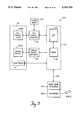
- FIG. 6is a system state diagram for the ultrasound system of FIG. 1.
- FIG. 7(a) through FIG. 7(e)are plan views of the control panel of FIG. 2 displaying menu changes in response to ultrasound system mode selections.
- FIG. 8is a plan view of a second control panel of the invention displaying the non-imaging system control menu.
- FIG. 9is a block diagram of a controller for implementing the ultrasound system control panel of FIG. 1.
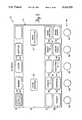
- FIG. 1there is shown a medical ultrasound imaging system 1 having an ultrasonic imaging probe 3 for imaging a patient, and a display 5 for displaying the ultrasound image generated by the system.
- Two menu driven control panels 10 and 10'provide an improved user interface to the ultrasound system according to the invention.
- the menu driven control panel 10 of the ultrasound imaging system 1 of FIG. 1features a flat menu hierarchy to partition the ultrasound system controls into smaller control sets specific to each of the different system modes.
- the control setsare divided into menu items, with each menu item typically controlling one system function.
- Control panel 10includes a flat electroluminescent touch panel 12 (EL panel) and soft controls 14 (FIG. 1) for displaying menu items to the user.
- the usertouches a menu item displayed on the EL panel to select that menu item, and the ultrasound system responds accordingly.
- a row of soft controls 14, which are rotatable soft controls in the preferred embodiments described herein,is positioned below and adjacent to the EL panel. Each rotatable control operates according to a corresponding function displayed on the adjacent EL panel.
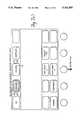
- the minimum control set menu displayed on the EL panel 12is divided into three groups of controls: a control set selection group 16 located at the top of the EL panel, a functional control group 19 located at the center of the EL panel, and a rotatable control group 21 located at the bottom of the EL panel adjacent to the row of rotatable controls 14.
- the control set selection group 16contains the control set entry points for each of the individual valid ultrasound modes, and remains available to the user regardless of the current operating mode of the system. Control set selection group 16 allows the user to select the 2D control set from menu item 18, the M-Mode control set from menu item 20, the COLOR control set from menu item 22, or the DOPPLER control set from menu item 24. If, for instance, a linear transducer is connected to the system and is active, M Mode is an invalid mode and therefore, menu item 20 will be empty.
- the menu itemWhen the user selects a control set by touching the appropriate control set selection menu item, the menu item is highlighted, and the remainder of the EL panel below the control set selection group 16 is reformatted to display the selected control set.
- the selected control setmay display as menu items only valid functions for the selected system mode.
- the 2D control grouphas been selected and menu item 18 is highlighted (shown as cross-hatching) indicating that the other groups of the EL panel display the 2D control set.
- the user activates more than one system mode simultaneouslye.g., in a composite mode
- only the last selected control groupis displayed and the activated system modes are indicated in the appropriate control set menu item. Composite modes are discussed in detail below.
- Functional control group 19displays menu items offering the user various functions available in the selected control set.
- the 2D control setoffers the user an on/off EDGE ENHANCE function, menu item 23, and an on/off HIGH RESOLUTION function, menu item 27. Again, the desired function is activated by touching the corresponding menu item.
- Rotatable control group 21displays menu items indicating the function assigned or assignable to each of the rotatable controls 14 for the selected control set.
- the rotatable controls shown in FIG. 2, and discussed below,are for the 2D control set.
- Rotatable control 25controls the ultrasound system transmit power as indicated by the POWER menu item 26 adjacent to the control.
- Rotatable control 28has dual functionality and controls either image persistence as indicated by the PERSIST menu item 30 or image compression as indicated by the COMPRESS menu item 32.
- the userselects the function of control 28 by touching either PERSIST or COMPRESS.
- the selected menu itemis highlighted.
- the menu item associated with a rotatable controlmay also display the state of the control relating to that menu item, e.g., PERSIST menu item 30 also shows that rotatable control 28 has previously selected persistence mode 2 indicated by numeral 34.
- Rotatable control 36controls the 2D image post processing as indicated by the POST PROC menu item 44 adjacent to the control.
- letter 45indicates the current post processing selection, e.g., post processing map B.
- Rotatable control 38also has dual functionality and controls either the physiological trace (e.g., an ECG trace displayed along with the ultrasound image) sweep rate as indicated by the SWEEP menu item 46 or linear angle as indicated by the LINEAR ANGLE menu item 48.
- the SWEEP menu itemis only displayed when the physiological measurement devices are configured to be operational, and the LINEAR ANGLE menu item is only displayed when a linear imaging transducer is active.
- the userselects the function of control 38 by touching either SWEEP or LINEAR ANGLE, and the selected menu item is highlighted.
- the SWEEP menu itemalso displays the current physiological trace sweep rate indicated by numeral 47, e.g., here indicating 50 mm/sec.
- Rotatable control 40also has dual functionality and controls either the image position as indicated by the IMAGE POSITION menu item 50 or image width as indicated by the IMAGE WIDTH menu item 52.
- the IMAGE POSITION menu itemis only displayed when the 2D image is reduced in size.
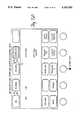
- EL panel 12displays the M mode control set activated by selecting the M MODE menu item 20 of the control set selection group 16.
- the M MODE menu item 20is illuminated (shown by cross-hatching) to indicate that the EL panel menu is displaying the M mode control set.
- the M mode control sethas fewer menu items than the 2D control set of FIG. 2.
- functional control group 19contains no menu items.
- Rotatable control 25retains it control over the ultrasound system transmit power as indicated by POWER menu item 26.
- Rotatable control 28retains control over image compression as indicated by COMPRESS menu item 32, but no longer optionally controls persistence, i.e., menu item 30 is now empty.
- Rotatable control 36now has dual functionality with M mode preprocessing now available on PRE PROC menu item 42 in addition to image postprocessing available on POST PROC menu item 44.
- Rotatable control 38controls the M mode trace sweep rate (the physiological trace sweep rate is constrained to be the same as the M mode trace sweep rate in M mode) as indicated by SWEEP menu item 46, but no longer optionally controls the linear angle, i.e., menu item 48 is empty.
- Rotatable control 40has no function in the M mode control set.
- POST PROCis set to B in the 2D and A in the M mode, as indicated by letter 45 of the POST PROC menu item 44 of FIGS. 1 and 2, respectively.
- the physiological trace sweep rateis set to 50 mm/sec in the 2D mode
- the M mode sweep rateis set to 100 mm/sec, as indicated by numeral 47 of SWEEP menu item 46 of FIGS. 1 and 2, respectively.
- EL panel 12displays the color flow imaging mode control set activated by selecting the COLOR menu item 22 of the control set selection group 16.
- the COLOR menu item 22is illuminated (shown by cross-hatching) to indicate that the EL panel menu is displaying the color flow imaging control set.
- Functional control group 19 of the color flow imaging control setfeatures a velocity tag function indicated by VELOCITY TAG menu item 54.
- the functions of the rotatable controlshave also been redefined.
- Rotatable control 25now controls color flow gain as indicated by GAIN menu item 26.
- Rotatable control 28now optionally controls either color flow persistence as indicated by PERSIST menu item 30 or color scale as indicated by SCALE menu item 32.
- Rotatable control 36now optionally controls color flow baseline as indicated by BASELINE menu item 42 or color flow process as indicated by PROCESS menu item 44.
- Rotatable control 38now optionally controls either the color map selection as indicated by MAP menu item 46 or linear sector angle indicated by LINEAR ANGLE menu item 48. Again, the linear probe must be active to display LINEAR ANGLE menu item 48.
- Rotatable control 40has no function in this control set.
- the selection of VELOCITY TAG menu item 54highlights the menu item (shown by cross-hatching) and causes the TAG 1 menu item 56 and TAG 2 menu item 58 to appear in the functional control group 19, and the TAG POSITION menu item 27 to appear over rotatable control 25.
- the TAG 1 and TAG 2 menu itemsoperate in tandem such that exactly one of the TAG 1 or TAG 2 items is always selected.
- velocity tag 1is selected as indicated by the highlighted TAG 1 menu item 56.
- Rotatable control 25now optionally controls the position of color tag 1 as indicated by the TAG POSITION menu item 27 or the color gain indicated by the GAIN menu item 26. Rotatable control 25 would optionally control the position of color tag 2 if the TAG 2 menu item 58 were selected.
- EL panel 12displays the Doppler imaging mode control set activated by selecting the DOPPLER menu item 24 of the control set selection group 16.
- the DOPPLER menu item 24is highlighted (shown by cross-hatching) to indicate that the EL panel menu is displaying the Doppler imaging mode control set.
- Functional control group 19 of the Doppler imaging control setfeatures a pulsed wave Doppler function indicated by the PW menu item 60, a continuous wave Doppler function indicated by the CW menu item 62, and a spectral display function indicated by the SPECTRAL menu item 64.
- the PW menu item 60 and the CW menu item 62operate in tandem such that exactly one of the PW or CW menu item is selected at any one time, i.e., the user may select either the pulsed wave or the continuous wave Doppler mode, but not both.
- FIG. 5(a)shows PW as the selected mode as indicated by the highlighted PW menu item 60, and SPECTRAL menu item 64 as unselected.
- Rotatable control 25optionally controls either the Doppler audio volume as indicated by VOLUME menu item 27 or the Doppler gain as indicated by GAIN menu item 26.
- the VOLUME menu itemis displayed when the Doppler audio signal has been activated by other system controls. Separate VOLUME and GAIN control values are retained by the system for the PW and CW modes.
- Rotatable control 38again controls the linear angle as indicated by LINEAR ANGLE menu item 48, but is only displayed when a linear probe is connected to the system.
- Rotatable control 40optionally controls the Doppler gate angle as indicated by the GATE ANGLE menu item 50 or the variable low frequency cutoff of the Doppler audio filter as indicated by the FILTER menu item 52.
- FILTER menu item 52also displays the current filter setting, here shown as 400 Hz.
- the selection of the SPECTRAL menu item 64highlights the menu item (shown by cross-hatching) and causes the SPECTRAL INVERT menu item 66 to appear in the functional control group 19. Selection of the SPECTRAL menu item also causes several new rotatable control menu items to appear.
- Rotatable control 28now controls the scale of the displayed Doppler spectrum as indicated by the SCALE menu item 32.
- Rotatable control 36now optionally controls either the baseline of the displayed Doppler spectrum as indicated by the BASELINE menu item 42 or the Doppler spectral processing as indicated by the PROCESS menu item 44.
- Rotatable control 38now optionally controls either the spectral sweep rate as indicated by the SWEEP menu control 46, or the linear angle as indicated by the LINEAR ANGLE menu item 48.
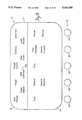
- FIG. 6there is shown a table of ultrasound system states describing the various ultrasound system modalities available.
- the left hand columnshows the current state of the system
- the top row of the tableshows the input to the system, i.e., the menu item selection made by the user
- the interior of the tableshow the system state that results from the system input.
- the system inputs listed as 2D, MMODE, COLOR, and DOPPLERcorrespond to the control set selection group 16 (FIG. 2) menu items 18, 20, 22, and 24, respectively.
- the PW, CW, and SPECTRAL system inputscorrespond to the DOPPLER control set functional control group 19 (FIGS.
- the TRIGGER system inputis a hard-wired system control not displayed on the EL panel menu, and when activated causes the ultrasound image to be formed only upon the occurrence of some external event such as the R wave of an ECG trace.
- the imageremains frozen during the period between triggers. Furthermore, the image is also frozen if the system is put into a Doppler search state, which allows the user to listen to high quality Doppler audio while positioning the Doppler gate in PW or the line cursor in CW.
- the systemmay always be returned to the nominal 2D imaging mode by selecting the 2D system input, i.e., the 2D menu item 18 (FIG. 2).
- the 2D menu item 18FIG. 2
- the systementers the 2D/M MODE(MM) state and the EL panel appears as shown in FIG. 3.
- the systemWhen the system is in the 2D mode and COLOR menu item 22 is selected, the system enters the 2D/COLOR (CF) state and the EL panel appears as shown in FIG. 4(a).
- the systemWhen the system is in the 2D mode and the DOPPLER menu item 24 is selected, the system enters the 2D(Triggered)/PW DOPPLER-AUDIO (PWA) state, and the EL panel appears as shown in FIG. 5(a).
- PWADOPPLER mode
- the usermay enter the PW search mode (PWx), the PW spectral mode (PWS), the CW search mode (CWx), or the CW spectral mode (CWS), by choosing the appropriate system inputs according to the state table.
- the M MODE, COLOR and DOPPLER system inputsalso operate to toggle the system out of the corresponding mode. For instance, if the system is in the 2D/MM state and the M MODE menu item 20 (FIG. 3) is selected, the system will return to the 2D state. Similarly, if the system is in the 2D/CF state and the COLOR menu item 22 (FIG. 4(a)) is selected, the system will return to the 2D state. If the system is in any 2D/PW or 2D/CW Doppler state and the DOPPLER menu item (FIG. 5(a)) is selected, the system will return to the 2D state.
- the systemWhen the system is in the 2D/MM state and COLOR menu item 22 (FIG. 3) is selected, the system enters the 2D/CF/MM composite mode state and the EL panel displays the color flow control set of FIG. 4(a).
- the EL panelwould display the M mode control set of FIG. 3 if the system were first put into the 2D/CF state and then M MODE was selected to put the system in the 2D/CF/MM composite state. If the system is in the 2D/CF/MM state and DOPPLER is selected, the system enters the 2D/CF/PWx composite state and the EL panel appears as shown in FIG. 5(a).
- the PWx Doppler modehas replace the M Mode since simultaneous Doppler and M Mode are not allowed by the system.
- FIGS. 6(a) through 6(e)An example of the EL panel menu response to changing system states is shown by FIGS. 6(a) through 6(e).
- the nominal 2D system stateis reflected by the EL panel menu of FIG. 7(a) which shows the 2D control set of FIG. 2.
- M MODE menu item 20The user then selects M MODE menu item 20.
- the systementers the 2D/CF/MM composite mode and the EL panel responds as shown in FIG. 7(c) by displaying the M Mode control set of FIG. 3.
- An asterisk 70is displayed in the COLOR menu item 22 to indicate that color flow mode is still active although the M mode control set is currently displayed.
- the color flow control setis available to the user, without changing the system state, by selecting the COLOR* menu item 22.
- the userBy selecting the DOPPLER menu item 24 the user then causes the system to enter the 2D/CF/Pwx composite color flow Doppler mode and the EL panel changes as shown in FIG. 7(d) to display the Doppler control set of FIG. 5(a). As discussed above, the Doppler mode has replaced M Mode. The color flow mode remains active as indicated by the asterisk 70 displayed in the COLOR menu item 22.
- the userBy selecting the COLOR* menu item 22 the user causes the EL panel to change as shown in FIG. 7(e) to display the color flow control set of FIG. 4(a).
- the systemremains in the 2D/CF/PWx color flow Doppler mode, i.e., the displayed control set changes from the Doppler control set of FIG. 7(d) to the color flow control set of FIG. 7(e) but the system state does not change.
- An asterisk 72is now displayed in the DOPPLER menu item 24 to indicate that the Doppler mode is still active although the color flow control set is currently shown in the EL panel.
- the Doppler control setmay be redisplayed on the EL panel without changing the system state by selecting the DOPPLER* menu item 24.
- EL panel 12'may be the same EL panel 12 of FIG. 2 with the non-imaging related functions displayed in place of the imaging function, but preferably EL panel 12' is a separate panel mounted adjacent to EL panel 12 so that the user may have imaging and non-imaging controls simultaneously available. It will be appreciated by those skilled in the art that a single EL panel large enough to display both the imaging and non-imaging control sets may be used in place of two separate panels.
- the same flat menu hierarchyis employed with the non-imaging controls.
- the control set selection group 16'displays menu items of available control sets to the user, and functional control group 19' displays menu items available in the selected control set.
- the VCR CONTROLS menu item 100has been selected, and the functional control group 19' displays the familiar VCR control menu items.
- Control panel 10is coupled to a keyboard controller 110 which includes a microprocessor portion 112 that responds to menu handler software instructions stored in a memory 114.
- EL touch panel 12(FIG. 1) is shown as two portions, touch panel 12(a) and EL panel display 12(b).
- the touch panel 12(a)is connected to the controller 110 through a touch panel driver circuit 116 which allows the controller to communicate with the touch panel, i.e., enable the touch panel to respond to various input and communicate received input to the controller.
- the EL panel display 12(b)is connected to the controller through an EL panel video driver 118 for displaying menu items on the panel in response to the keyboard controller.
- a video memory 120stores the EL panel menu items in video format.
- a data communication channel 122is connected from the keyboard controller 112 to the rest of the ultrasound system including the display subsystem 124 and scanner subsystem 126.
- the keyboard controllerissues commands to the display and scanner subsystems to cause the system to enter various modes in response to user input to the control panel.
Landscapes
- Engineering & Computer Science (AREA)
- Health & Medical Sciences (AREA)
- Life Sciences & Earth Sciences (AREA)
- Physics & Mathematics (AREA)
- Radar, Positioning & Navigation (AREA)
- Remote Sensing (AREA)
- General Physics & Mathematics (AREA)
- Pathology (AREA)
- General Health & Medical Sciences (AREA)
- Computer Networks & Wireless Communication (AREA)
- Heart & Thoracic Surgery (AREA)
- Veterinary Medicine (AREA)
- Radiology & Medical Imaging (AREA)
- Biomedical Technology (AREA)
- Biophysics (AREA)
- Medical Informatics (AREA)
- Molecular Biology (AREA)
- Surgery (AREA)
- Animal Behavior & Ethology (AREA)
- Nuclear Medicine, Radiotherapy & Molecular Imaging (AREA)
- Public Health (AREA)
- Acoustics & Sound (AREA)
- Human Computer Interaction (AREA)
- Chemical & Material Sciences (AREA)
- Analytical Chemistry (AREA)
- Biochemistry (AREA)
- Immunology (AREA)
- Ultra Sonic Daignosis Equipment (AREA)
- Investigating Or Analyzing Materials By The Use Of Ultrasonic Waves (AREA)
Abstract
Description
Claims (20)
Priority Applications (3)
| Application Number | Priority Date | Filing Date | Title |
|---|---|---|---|
| US07/720,149US5161535A (en) | 1991-06-24 | 1991-06-24 | Medical ultrasound imaging system having a partitioned menu |
| EP92110400AEP0520338A2 (en) | 1991-06-24 | 1992-06-19 | A medical ultrasound imaging system having a partitioned menu |
| JP18984492AJPH05220142A (en) | 1991-06-24 | 1992-06-24 | Ultrasonic video apparatus |
Applications Claiming Priority (1)
| Application Number | Priority Date | Filing Date | Title |
|---|---|---|---|
| US07/720,149US5161535A (en) | 1991-06-24 | 1991-06-24 | Medical ultrasound imaging system having a partitioned menu |
Publications (1)
| Publication Number | Publication Date |
|---|---|
| US5161535Atrue US5161535A (en) | 1992-11-10 |
Family
ID=24892844
Family Applications (1)
| Application Number | Title | Priority Date | Filing Date |
|---|---|---|---|
| US07/720,149Expired - LifetimeUS5161535A (en) | 1991-06-24 | 1991-06-24 | Medical ultrasound imaging system having a partitioned menu |
Country Status (3)
| Country | Link |
|---|---|
| US (1) | US5161535A (en) |
| EP (1) | EP0520338A2 (en) |
| JP (1) | JPH05220142A (en) |
Cited By (63)
| Publication number | Priority date | Publication date | Assignee | Title |
|---|---|---|---|---|
| US5261824A (en)* | 1992-01-13 | 1993-11-16 | Ness Allan H | Sales promotion vehicle for demonstrating mobile electronic accessories |
| US5315999A (en)* | 1993-04-21 | 1994-05-31 | Hewlett-Packard Company | Ultrasound imaging system having user preset modes |
| USD354353S (en) | 1993-02-15 | 1995-01-10 | Fujitsu Limited | Ultrasound diagnostic instrument |
| US5394871A (en)* | 1992-06-25 | 1995-03-07 | Siemens Aktiengesellschaft | Medical diagnostics installation |
| WO1995015521A3 (en)* | 1993-11-29 | 1995-07-20 | Perception Inc | Pc based ultrasound device with virtual control user interface |
| US5627567A (en)* | 1993-04-27 | 1997-05-06 | Hewlett-Packard Company | Method and apparatus for adaptive touch recognition in a touch sensitive user interface |
| US5919138A (en)* | 1997-08-22 | 1999-07-06 | Acuson Corporation | Ultrasound imaging system user interface |
| US5963198A (en)* | 1996-12-23 | 1999-10-05 | Snap-On Technologies, Inc. | Low-cost user interface for refrigerant recycling machine |
| US6072473A (en)* | 1992-03-26 | 2000-06-06 | Aerospatiale-Societe Nationale Industrielle | Method and device for multimode and multifunction communication between an operator and one or more processors |
| US6142940A (en)* | 1998-10-06 | 2000-11-07 | Scimed Life Systems, Inc. | Control panel for intravascular ultrasonic imaging system |
| US6177923B1 (en) | 1994-12-30 | 2001-01-23 | Acuson Corporation | Imaging modality showing energy and velocity |
| US6201900B1 (en)* | 1996-02-29 | 2001-03-13 | Acuson Corporation | Multiple ultrasound image registration system, method and transducer |
| US6468212B1 (en)* | 1997-04-19 | 2002-10-22 | Adalberto Vara | User control interface for an ultrasound processor |
| US20030081008A1 (en)* | 2001-10-29 | 2003-05-01 | Seo Byung-Ryul | Method and apparatus for controlling an electronic device via a menu displayed on a display screen of the electronic device |
| US6599244B1 (en) | 1999-12-23 | 2003-07-29 | Siemens Medical Solutions, Usa, Inc. | Ultrasound system and method for direct manipulation interface |
| US20030153832A1 (en)* | 2002-01-22 | 2003-08-14 | Jona Zumeris | System and method for smart monitoring within a body |
| US20030153831A1 (en)* | 2002-01-22 | 2003-08-14 | Jona Zumeris | System and method for detection of motion |
| US20040001080A1 (en)* | 2002-06-27 | 2004-01-01 | Fowkes Kenneth M. | Method and system for facilitating selection of stored medical images |
| US20040039286A1 (en)* | 2002-08-26 | 2004-02-26 | The Cleveland Clinic Foundation | System and method of aquiring blood-vessel data |
| US20040102706A1 (en)* | 2001-08-28 | 2004-05-27 | Donald Christopher | Automatic optimization of doppler display parameters |
| US20040109028A1 (en)* | 2002-12-10 | 2004-06-10 | Siemens Medical Solutions Usa, Inc. | Medical imaging programmable custom user interface system and method |
| US20040138569A1 (en)* | 1999-08-20 | 2004-07-15 | Sorin Grunwald | User interface for handheld imaging devices |
| US20050041282A1 (en)* | 2003-08-21 | 2005-02-24 | Frank Rudolph | Operating menu for a surgical microscope |
| US20050054920A1 (en)* | 2003-09-10 | 2005-03-10 | Washburn Michael Joseph | Method and apparatus for controlling ultrasound systems |
| US20050107701A1 (en)* | 2003-11-19 | 2005-05-19 | Dubberstein David T. | Automatic color gain adjustments |
| US20050114175A1 (en)* | 2003-11-25 | 2005-05-26 | O'dea Paul J. | Method and apparatus for managing ultrasound examination information |
| US20050149863A1 (en)* | 2003-09-11 | 2005-07-07 | Yoshinaga Kato | System, recording medium & program for inputting operation condition of instrument |
| US20060100520A1 (en)* | 1999-08-20 | 2006-05-11 | Mo Larry Y L | Ultrasound system with iterative high pass filter selection |
| US20060101581A1 (en)* | 2004-10-29 | 2006-05-18 | Blanchard Frederick W | Patient support apparatus |
| US20060178839A1 (en)* | 1998-04-28 | 2006-08-10 | Atsushi Maki | Optical measurement instrument and optical measurement method |
| US20060184029A1 (en)* | 2005-01-13 | 2006-08-17 | Ronen Haim | Ultrasound guiding system and method for vascular access and operation mode |
| US20060264746A1 (en)* | 2003-05-27 | 2006-11-23 | Koninklijke Philips Electronics N.V. | Diagnostic imaging system control with multiple control functions |
| US20070129625A1 (en)* | 2005-11-21 | 2007-06-07 | Boston Scientific Scimed Systems, Inc. | Systems and methods for detecting the presence of abnormalities in a medical image |
| US20070225590A1 (en)* | 2006-01-13 | 2007-09-27 | Boston Scientific Scimed, Inc. | Control panel for a medical imaging system |
| US20080072151A1 (en)* | 2006-09-19 | 2008-03-20 | Song Tai-Kyong | Context aware user interface for medical diagnostic imaging, such as ultrasound imaging |
| US20080139932A1 (en)* | 2006-12-07 | 2008-06-12 | Medison Co., Ltd. | Ultrasound system |
| US20080146922A1 (en)* | 2006-10-24 | 2008-06-19 | Zonare Medical Systems, Inc. | Control of user interfaces and displays for portable ultrasound unit and docking station |
| US20080215982A1 (en)* | 2007-03-02 | 2008-09-04 | General Electric Company | Method and apparatus for controlling ultrasound systems with physical controls |
| US20090109231A1 (en)* | 2007-10-26 | 2009-04-30 | Sung Nam Kim | Imaging Device Providing Soft Buttons and Method of Changing Attributes of the Soft Buttons |
| US20100023886A1 (en)* | 2008-07-25 | 2010-01-28 | Medison Co., Ltd. | Method and apparatus for providing customized interface in ultrasound system |
| US20100189329A1 (en)* | 2004-10-07 | 2010-07-29 | Zonare Medical Systems Inc. | Ultrasound Imaging System Parameter Optimization Via Fuzzy Logic |
| US8002705B1 (en) | 2005-07-22 | 2011-08-23 | Zonaire Medical Systems, Inc. | Continuous transmit focusing method and apparatus for ultrasound imaging system |
| US8028317B1 (en)* | 2004-02-20 | 2011-09-27 | Broadcast Pix, Inc. | Integrated live video production system |
| US20110231996A1 (en)* | 2004-10-29 | 2011-09-29 | Stryker Corporation | Hospital bed |
| US8102457B1 (en) | 1997-07-09 | 2012-01-24 | Flashpoint Technology, Inc. | Method and apparatus for correcting aspect ratio in a camera graphical user interface |
| US8127232B2 (en) | 1998-12-31 | 2012-02-28 | Flashpoint Technology, Inc. | Method and apparatus for editing heterogeneous media objects in a digital imaging device |
| US20130261447A1 (en)* | 2012-04-02 | 2013-10-03 | Fujifilm Corporation | Ultrasound diagnostic apparatus |
| US8679018B2 (en) | 1999-08-20 | 2014-03-25 | Zonare Medical Systems, Inc. | Broad-beam imaging |
| US8784318B1 (en) | 2005-07-22 | 2014-07-22 | Zonare Medical Systems, Inc. | Aberration correction using channel data in ultrasound imaging system |
| CN103945770A (en)* | 2011-11-21 | 2014-07-23 | 日立阿洛卡医疗株式会社 | Ultrasonic diagnostic device |
| US8824754B2 (en) | 2007-02-23 | 2014-09-02 | General Electric Company | Method and apparatus for generating variable resolution medical images |
| CN104545997A (en)* | 2014-11-25 | 2015-04-29 | 深圳市理邦精密仪器股份有限公司 | Multi-screen interactive operation method and multi-screen interaction system for ultrasonic equipment |
| US20150119699A1 (en)* | 2013-10-24 | 2015-04-30 | Varian Medical Systems, Inc. | System and method for triggering an imaging process |
| US9060669B1 (en) | 2007-12-20 | 2015-06-23 | Zonare Medical Systems, Inc. | System and method for providing variable ultrasound array processing in a post-storage mode |
| US9224145B1 (en) | 2006-08-30 | 2015-12-29 | Qurio Holdings, Inc. | Venue based digital rights using capture device with digital watermarking capability |
| US20160007965A1 (en)* | 2014-07-09 | 2016-01-14 | Edan Instruments, Inc. | Portable ultrasound user interface and resource management systems and methods |
| US20160162163A1 (en)* | 2014-12-08 | 2016-06-09 | Samsung Medison Co., Ltd. | Input apparatus and medical image apparatus comprising the same |
| US10052249B2 (en) | 2004-10-29 | 2018-08-21 | Stryker Corporation | Patient support with improved control |
| US10070845B2 (en) | 2012-09-25 | 2018-09-11 | Fujifilm Corporation | Ultrasound diagnostic apparatus displaying body marks each of which indicates an examination position by the ultrasound probe |
| US10456111B2 (en) | 2006-12-07 | 2019-10-29 | Samsung Medison Co., Ltd. | Ultrasound system and signal processing unit configured for time gain and lateral gain compensation |
| US10945706B2 (en) | 2017-05-05 | 2021-03-16 | Biim Ultrasound As | Hand held ultrasound probe |
| US11246776B2 (en) | 2005-12-19 | 2022-02-15 | Stryker Corporation | Patient support with improved control |
| CN115956948A (en)* | 2022-12-20 | 2023-04-14 | 武汉联影医疗科技有限公司 | Ultrasonic scanning equipment and parameter layout method and system thereof |
Families Citing this family (10)
| Publication number | Priority date | Publication date | Assignee | Title |
|---|---|---|---|---|
| US6030344A (en)* | 1996-12-04 | 2000-02-29 | Acuson Corporation | Methods and apparatus for ultrasound image quantification |
| US6086539A (en) | 1996-12-04 | 2000-07-11 | Acuson Corporation | Methods and apparatus for ultrasound image quantification |
| KR100197583B1 (en)* | 1997-02-04 | 1999-06-15 | 이민화 | Ultrasonic wave diagnosis device having monitor for patients |
| JP4737859B2 (en)* | 2001-03-29 | 2011-08-03 | 東芝医用システムエンジニアリング株式会社 | Ultrasonic diagnostic apparatus, X-ray CT apparatus, and display control program |
| JP4828731B2 (en)* | 2001-07-16 | 2011-11-30 | 日立アロカメディカル株式会社 | Ultrasonic diagnostic equipment |
| US8096943B2 (en) | 2006-12-04 | 2012-01-17 | University Of Washington Through Its Center For Commercialization | Flexible endoscope tip bending mechanism using optical fiber as compression member |
| KR101115423B1 (en)* | 2010-06-14 | 2012-02-15 | 알피니언메디칼시스템 주식회사 | Ultrasonic Diagnostic Device and Control Method |
| JP4854811B2 (en)* | 2011-02-07 | 2012-01-18 | 東芝医用システムエンジニアリング株式会社 | Ultrasonic diagnostic apparatus, X-ray CT apparatus, and display control program |
| KR101925058B1 (en)* | 2012-04-26 | 2018-12-04 | 삼성전자주식회사 | The method and apparatus for dispalying function of a button of an ultrasound apparatus on the button |
| WO2017145992A1 (en)* | 2016-02-22 | 2017-08-31 | 富士フイルム株式会社 | Display device and display method for acoustic wave images |
Citations (6)
| Publication number | Priority date | Publication date | Assignee | Title |
|---|---|---|---|---|
| US4608662A (en)* | 1980-11-07 | 1986-08-26 | Hitachi, Ltd. | Method for editing document |
| US4644486A (en)* | 1984-01-09 | 1987-02-17 | Hewlett-Packard Company | Vector network analyzer with integral processor |
| US4821030A (en)* | 1986-12-19 | 1989-04-11 | Tektronix, Inc. | Touchscreen feedback system |
| US4870561A (en)* | 1986-09-01 | 1989-09-26 | Hewlett-Packard Company | User interface simulation and management for program-controlled apparatus |
| US4922909A (en)* | 1987-07-17 | 1990-05-08 | Little James H | Video monitoring and reapposition monitoring apparatus and methods |
| US5056059A (en)* | 1987-09-10 | 1991-10-08 | Hewlett-Packard Company | Medical monitoring system interface |
Family Cites Families (1)
| Publication number | Priority date | Publication date | Assignee | Title |
|---|---|---|---|---|
| JPH01172997A (en)* | 1987-12-23 | 1989-07-07 | Internatl Business Mach Corp <Ibm> | Graphic customization of memu display |
- 1991
- 1991-06-24USUS07/720,149patent/US5161535A/ennot_activeExpired - Lifetime
- 1992
- 1992-06-19EPEP92110400Apatent/EP0520338A2/ennot_activeCeased
- 1992-06-24JPJP18984492Apatent/JPH05220142A/enactivePending
Patent Citations (6)
| Publication number | Priority date | Publication date | Assignee | Title |
|---|---|---|---|---|
| US4608662A (en)* | 1980-11-07 | 1986-08-26 | Hitachi, Ltd. | Method for editing document |
| US4644486A (en)* | 1984-01-09 | 1987-02-17 | Hewlett-Packard Company | Vector network analyzer with integral processor |
| US4870561A (en)* | 1986-09-01 | 1989-09-26 | Hewlett-Packard Company | User interface simulation and management for program-controlled apparatus |
| US4821030A (en)* | 1986-12-19 | 1989-04-11 | Tektronix, Inc. | Touchscreen feedback system |
| US4922909A (en)* | 1987-07-17 | 1990-05-08 | Little James H | Video monitoring and reapposition monitoring apparatus and methods |
| US5056059A (en)* | 1987-09-10 | 1991-10-08 | Hewlett-Packard Company | Medical monitoring system interface |
Non-Patent Citations (4)
| Title |
|---|
| GE Radius Ultrasound System advertisement.* |
| Toshiba SSH 140A advertisement.* |
| Toshiba SSH-140A advertisement. |
| Ultramark 9 advertisement.* |
Cited By (114)
| Publication number | Priority date | Publication date | Assignee | Title |
|---|---|---|---|---|
| US5261824A (en)* | 1992-01-13 | 1993-11-16 | Ness Allan H | Sales promotion vehicle for demonstrating mobile electronic accessories |
| US6072473A (en)* | 1992-03-26 | 2000-06-06 | Aerospatiale-Societe Nationale Industrielle | Method and device for multimode and multifunction communication between an operator and one or more processors |
| US5394871A (en)* | 1992-06-25 | 1995-03-07 | Siemens Aktiengesellschaft | Medical diagnostics installation |
| USD354353S (en) | 1993-02-15 | 1995-01-10 | Fujitsu Limited | Ultrasound diagnostic instrument |
| US5315999A (en)* | 1993-04-21 | 1994-05-31 | Hewlett-Packard Company | Ultrasound imaging system having user preset modes |
| DE4406079A1 (en)* | 1993-04-21 | 1994-10-27 | Hewlett Packard Co | Ultrasound imaging system with user-preset modes |
| US5627567A (en)* | 1993-04-27 | 1997-05-06 | Hewlett-Packard Company | Method and apparatus for adaptive touch recognition in a touch sensitive user interface |
| US6063030A (en)* | 1993-11-29 | 2000-05-16 | Adalberto Vara | PC based ultrasound device with virtual control user interface |
| WO1995015521A3 (en)* | 1993-11-29 | 1995-07-20 | Perception Inc | Pc based ultrasound device with virtual control user interface |
| US6177923B1 (en) | 1994-12-30 | 2001-01-23 | Acuson Corporation | Imaging modality showing energy and velocity |
| US6201900B1 (en)* | 1996-02-29 | 2001-03-13 | Acuson Corporation | Multiple ultrasound image registration system, method and transducer |
| US6360027B1 (en)* | 1996-02-29 | 2002-03-19 | Acuson Corporation | Multiple ultrasound image registration system, method and transducer |
| US5963198A (en)* | 1996-12-23 | 1999-10-05 | Snap-On Technologies, Inc. | Low-cost user interface for refrigerant recycling machine |
| US6468212B1 (en)* | 1997-04-19 | 2002-10-22 | Adalberto Vara | User control interface for an ultrasound processor |
| US8102457B1 (en) | 1997-07-09 | 2012-01-24 | Flashpoint Technology, Inc. | Method and apparatus for correcting aspect ratio in a camera graphical user interface |
| US8970761B2 (en) | 1997-07-09 | 2015-03-03 | Flashpoint Technology, Inc. | Method and apparatus for correcting aspect ratio in a camera graphical user interface |
| US5919138A (en)* | 1997-08-22 | 1999-07-06 | Acuson Corporation | Ultrasound imaging system user interface |
| US20060178839A1 (en)* | 1998-04-28 | 2006-08-10 | Atsushi Maki | Optical measurement instrument and optical measurement method |
| US7359825B2 (en) | 1998-04-28 | 2008-04-15 | Hitachi, Ltd. | Optical measurement instrument and optical measurement method |
| US6361497B1 (en) | 1998-10-06 | 2002-03-26 | Scimed Life Systems, Inc. | Control panel for intravascular ultrasonic imaging system |
| US6142940A (en)* | 1998-10-06 | 2000-11-07 | Scimed Life Systems, Inc. | Control panel for intravascular ultrasonic imaging system |
| US8972867B1 (en) | 1998-12-31 | 2015-03-03 | Flashpoint Technology, Inc. | Method and apparatus for editing heterogeneous media objects in a digital imaging device |
| US8127232B2 (en) | 1998-12-31 | 2012-02-28 | Flashpoint Technology, Inc. | Method and apparatus for editing heterogeneous media objects in a digital imaging device |
| US8679018B2 (en) | 1999-08-20 | 2014-03-25 | Zonare Medical Systems, Inc. | Broad-beam imaging |
| US20060100520A1 (en)* | 1999-08-20 | 2006-05-11 | Mo Larry Y L | Ultrasound system with iterative high pass filter selection |
| US7022075B2 (en)* | 1999-08-20 | 2006-04-04 | Zonare Medical Systems, Inc. | User interface for handheld imaging devices |
| US20040138569A1 (en)* | 1999-08-20 | 2004-07-15 | Sorin Grunwald | User interface for handheld imaging devices |
| US20060116578A1 (en)* | 1999-08-20 | 2006-06-01 | Sorin Grunwald | User interface for handheld imaging devices |
| US8764661B2 (en) | 1999-08-20 | 2014-07-01 | Zonare Medical Systems, Inc. | Echolocation data generation |
| US6599244B1 (en) | 1999-12-23 | 2003-07-29 | Siemens Medical Solutions, Usa, Inc. | Ultrasound system and method for direct manipulation interface |
| US20040102706A1 (en)* | 2001-08-28 | 2004-05-27 | Donald Christopher | Automatic optimization of doppler display parameters |
| US20030081008A1 (en)* | 2001-10-29 | 2003-05-01 | Seo Byung-Ryul | Method and apparatus for controlling an electronic device via a menu displayed on a display screen of the electronic device |
| US20030153831A1 (en)* | 2002-01-22 | 2003-08-14 | Jona Zumeris | System and method for detection of motion |
| US6964640B2 (en) | 2002-01-22 | 2005-11-15 | P M G Medica L I D | System and method for detection of motion |
| US20030153832A1 (en)* | 2002-01-22 | 2003-08-14 | Jona Zumeris | System and method for smart monitoring within a body |
| US7536644B2 (en)* | 2002-06-27 | 2009-05-19 | Siemens Medical Solutions Usa, Inc. | Method and system for facilitating selection of stored medical images |
| US20040204965A1 (en)* | 2002-06-27 | 2004-10-14 | Gueck Wayne J. | Method and system for facilitating selection of stored medical image files |
| US20040001080A1 (en)* | 2002-06-27 | 2004-01-01 | Fowkes Kenneth M. | Method and system for facilitating selection of stored medical images |
| US8622910B2 (en) | 2002-08-26 | 2014-01-07 | The Cleveland Clinic Foundation | System and method of aquiring blood-vessel data |
| US20040039286A1 (en)* | 2002-08-26 | 2004-02-26 | The Cleveland Clinic Foundation | System and method of aquiring blood-vessel data |
| US7927275B2 (en) | 2002-08-26 | 2011-04-19 | The Cleveland Clinic Foundation | System and method of aquiring blood-vessel data |
| US20110208017A1 (en)* | 2002-08-26 | 2011-08-25 | Kuban Barry D | System and method of aquiring blood-vessel data |
| US20040109028A1 (en)* | 2002-12-10 | 2004-06-10 | Siemens Medical Solutions Usa, Inc. | Medical imaging programmable custom user interface system and method |
| US7904824B2 (en)* | 2002-12-10 | 2011-03-08 | Siemens Medical Solutions Usa, Inc. | Medical imaging programmable custom user interface system and method |
| US20060264746A1 (en)* | 2003-05-27 | 2006-11-23 | Koninklijke Philips Electronics N.V. | Diagnostic imaging system control with multiple control functions |
| US20050041282A1 (en)* | 2003-08-21 | 2005-02-24 | Frank Rudolph | Operating menu for a surgical microscope |
| US7594188B2 (en)* | 2003-08-21 | 2009-09-22 | Carl Zeiss Ag | Operating menu for a surgical microscope |
| US20050054920A1 (en)* | 2003-09-10 | 2005-03-10 | Washburn Michael Joseph | Method and apparatus for controlling ultrasound systems |
| US7052459B2 (en)* | 2003-09-10 | 2006-05-30 | General Electric Company | Method and apparatus for controlling ultrasound systems |
| US7336282B2 (en)* | 2003-09-11 | 2008-02-26 | Ricoh Company, Ltd. | System, recording medium and program for inputting operation condition of instrument |
| US20050149863A1 (en)* | 2003-09-11 | 2005-07-07 | Yoshinaga Kato | System, recording medium & program for inputting operation condition of instrument |
| US20050107701A1 (en)* | 2003-11-19 | 2005-05-19 | Dubberstein David T. | Automatic color gain adjustments |
| US6979295B2 (en) | 2003-11-19 | 2005-12-27 | Ge Medical Systems Global Technology Company, Llc | Automatic color gain adjustments |
| US20050114175A1 (en)* | 2003-11-25 | 2005-05-26 | O'dea Paul J. | Method and apparatus for managing ultrasound examination information |
| US8028317B1 (en)* | 2004-02-20 | 2011-09-27 | Broadcast Pix, Inc. | Integrated live video production system |
| US20100189329A1 (en)* | 2004-10-07 | 2010-07-29 | Zonare Medical Systems Inc. | Ultrasound Imaging System Parameter Optimization Via Fuzzy Logic |
| US8357094B2 (en) | 2004-10-07 | 2013-01-22 | Zonare Medical Systems Inc. | Ultrasound imaging system parameter optimization via fuzzy logic |
| US20110231996A1 (en)* | 2004-10-29 | 2011-09-29 | Stryker Corporation | Hospital bed |
| US11382813B2 (en) | 2004-10-29 | 2022-07-12 | Stryker Corporation | Patient support with improved control |
| US8413271B2 (en) | 2004-10-29 | 2013-04-09 | Stryker Corporation | Patient support apparatus |
| US10052249B2 (en) | 2004-10-29 | 2018-08-21 | Stryker Corporation | Patient support with improved control |
| US20060101581A1 (en)* | 2004-10-29 | 2006-05-18 | Blanchard Frederick W | Patient support apparatus |
| US9126571B2 (en) | 2004-10-29 | 2015-09-08 | Stryker Corporation | Hospital bed |
| US20060184029A1 (en)* | 2005-01-13 | 2006-08-17 | Ronen Haim | Ultrasound guiding system and method for vascular access and operation mode |
| US9198636B2 (en) | 2005-07-22 | 2015-12-01 | Shenzhen Mindray Bio-Medical Electronics Co., Ltd. | Continuous transmit focusing method and apparatus for ultrasound imaging system |
| US9901323B2 (en) | 2005-07-22 | 2018-02-27 | Shenzhen Mindray Bio-Medical Electronics Co., Ltd. | Aberration correction using channel data in ultrasound imaging system |
| US8002705B1 (en) | 2005-07-22 | 2011-08-23 | Zonaire Medical Systems, Inc. | Continuous transmit focusing method and apparatus for ultrasound imaging system |
| US8784318B1 (en) | 2005-07-22 | 2014-07-22 | Zonare Medical Systems, Inc. | Aberration correction using channel data in ultrasound imaging system |
| US8672846B2 (en) | 2005-07-22 | 2014-03-18 | Zonare Medical Systems, Inc. | Continuous transmit focusing method and apparatus for ultrasound imaging system |
| US20070129625A1 (en)* | 2005-11-21 | 2007-06-07 | Boston Scientific Scimed Systems, Inc. | Systems and methods for detecting the presence of abnormalities in a medical image |
| US11246776B2 (en) | 2005-12-19 | 2022-02-15 | Stryker Corporation | Patient support with improved control |
| US20070225590A1 (en)* | 2006-01-13 | 2007-09-27 | Boston Scientific Scimed, Inc. | Control panel for a medical imaging system |
| US9224145B1 (en) | 2006-08-30 | 2015-12-29 | Qurio Holdings, Inc. | Venue based digital rights using capture device with digital watermarking capability |
| US20080072151A1 (en)* | 2006-09-19 | 2008-03-20 | Song Tai-Kyong | Context aware user interface for medical diagnostic imaging, such as ultrasound imaging |
| US8286079B2 (en)* | 2006-09-19 | 2012-10-09 | Siemens Medical Solutions Usa, Inc. | Context aware user interface for medical diagnostic imaging, such as ultrasound imaging |
| WO2008051738A3 (en)* | 2006-10-24 | 2008-09-12 | Zonare Medical Systems Inc | Control of user interfaces and displays for portable ultrasound unit and docking station |
| US20080146922A1 (en)* | 2006-10-24 | 2008-06-19 | Zonare Medical Systems, Inc. | Control of user interfaces and displays for portable ultrasound unit and docking station |
| US10456111B2 (en) | 2006-12-07 | 2019-10-29 | Samsung Medison Co., Ltd. | Ultrasound system and signal processing unit configured for time gain and lateral gain compensation |
| US12193879B2 (en) | 2006-12-07 | 2025-01-14 | Samsung Medison Co. Ltd. | Ultrasound system and signal processing unit configured for time gain and lateral gain compensation |
| US8403855B2 (en) | 2006-12-07 | 2013-03-26 | Samsung Medison Co., Ltd. | Ultrasound system and signal processing unit configured for time gain and lateral gain compensation |
| US8016759B2 (en)* | 2006-12-07 | 2011-09-13 | Medison Co., Ltd. | Ultrasound system and signal processing unit configured for time gain and lateral gain compensation |
| US9259209B2 (en) | 2006-12-07 | 2016-02-16 | Samsung Medison Co., Ltd. | Ultrasound system and signal processing unit configured for time gain and lateral gain compensation |
| US9055920B2 (en) | 2006-12-07 | 2015-06-16 | Samsung Medison Co., Ltd. | Ultrasound system and signal processing unit configured for time gain and lateral gain compensation |
| US10321891B2 (en) | 2006-12-07 | 2019-06-18 | Samsung Medison Co., Ltd. | Ultrasound system and signal processing unit configured for time gain and lateral gain compensation |
| US20080139932A1 (en)* | 2006-12-07 | 2008-06-12 | Medison Co., Ltd. | Ultrasound system |
| US11633174B2 (en) | 2006-12-07 | 2023-04-25 | Samsung Medison Co., Ltd. | Ultrasound system and signal processing unit configured for Time Gain and Lateral Gain Compensation |
| US8824754B2 (en) | 2007-02-23 | 2014-09-02 | General Electric Company | Method and apparatus for generating variable resolution medical images |
| US20080215982A1 (en)* | 2007-03-02 | 2008-09-04 | General Electric Company | Method and apparatus for controlling ultrasound systems with physical controls |
| US9500944B2 (en) | 2007-03-02 | 2016-11-22 | General Electric Company | Method and apparatus for controlling ultrasound systems with physical controls |
| EP2056190A1 (en)* | 2007-10-26 | 2009-05-06 | Medison Co., Ltd. | Imaging device providing soft buttons and method of changing attributes of the soft buttons |
| US20090109231A1 (en)* | 2007-10-26 | 2009-04-30 | Sung Nam Kim | Imaging Device Providing Soft Buttons and Method of Changing Attributes of the Soft Buttons |
| US9060669B1 (en) | 2007-12-20 | 2015-06-23 | Zonare Medical Systems, Inc. | System and method for providing variable ultrasound array processing in a post-storage mode |
| US10085724B2 (en) | 2007-12-20 | 2018-10-02 | Shenzhen Mindray Bio-Medical Electronics Co., Ltd. | System and method for providing variable ultrasound array processing in a post-storage mode |
| US11103221B2 (en) | 2007-12-20 | 2021-08-31 | Shenzhen Mindray Bio-Medical Electronics Co., Ltd. | System and method for providing variable ultrasound array processing in a post-storage mode |
| US20100023886A1 (en)* | 2008-07-25 | 2010-01-28 | Medison Co., Ltd. | Method and apparatus for providing customized interface in ultrasound system |
| CN103945770A (en)* | 2011-11-21 | 2014-07-23 | 日立阿洛卡医疗株式会社 | Ultrasonic diagnostic device |
| US20140325442A1 (en)* | 2011-11-21 | 2014-10-30 | Hitachi Aloka Medical, Ltd. | Ultrasonic diagnosis apparatus |
| CN103945770B (en)* | 2011-11-21 | 2017-05-17 | 株式会社日立制作所 | Ultrasonic diagnostic device |
| US9778827B2 (en)* | 2011-11-21 | 2017-10-03 | Hitachi, Ltd. | Ultrasonic diagnosis apparatus |
| US9289186B2 (en)* | 2012-04-02 | 2016-03-22 | Fujifilm Corporation | Ultrasound diagnostic apparatus |
| US9526474B2 (en)* | 2012-04-02 | 2016-12-27 | Fujifilm Corporation | Ultrasound diagnostic apparatus |
| US20130261447A1 (en)* | 2012-04-02 | 2013-10-03 | Fujifilm Corporation | Ultrasound diagnostic apparatus |
| US20160081660A1 (en)* | 2012-04-02 | 2016-03-24 | Fujifilm Corporation | Ultrasound diagnostic apparatus |
| US10206660B2 (en) | 2012-09-25 | 2019-02-19 | Fujifilm Corporation | Ultrasound diagnostic method displaying body marks each of which indicates an examination position by the ultrasound probe |
| US10070845B2 (en) | 2012-09-25 | 2018-09-11 | Fujifilm Corporation | Ultrasound diagnostic apparatus displaying body marks each of which indicates an examination position by the ultrasound probe |
| US20150119699A1 (en)* | 2013-10-24 | 2015-04-30 | Varian Medical Systems, Inc. | System and method for triggering an imaging process |
| US20160007965A1 (en)* | 2014-07-09 | 2016-01-14 | Edan Instruments, Inc. | Portable ultrasound user interface and resource management systems and methods |
| US10617390B2 (en)* | 2014-07-09 | 2020-04-14 | Edan Instruments, Inc. | Portable ultrasound user interface and resource management systems and methods |
| CN104545997A (en)* | 2014-11-25 | 2015-04-29 | 深圳市理邦精密仪器股份有限公司 | Multi-screen interactive operation method and multi-screen interaction system for ultrasonic equipment |
| US20160162163A1 (en)* | 2014-12-08 | 2016-06-09 | Samsung Medison Co., Ltd. | Input apparatus and medical image apparatus comprising the same |
| US10191632B2 (en)* | 2014-12-08 | 2019-01-29 | Samsung Medison Co., Ltd. | Input apparatus and medical image apparatus comprising the same |
| US10945706B2 (en) | 2017-05-05 | 2021-03-16 | Biim Ultrasound As | Hand held ultrasound probe |
| US11744551B2 (en) | 2017-05-05 | 2023-09-05 | Biim Ultrasound As | Hand held ultrasound probe |
| CN115956948A (en)* | 2022-12-20 | 2023-04-14 | 武汉联影医疗科技有限公司 | Ultrasonic scanning equipment and parameter layout method and system thereof |
Also Published As
| Publication number | Publication date |
|---|---|
| EP0520338A3 (en) | 1994-03-30 |
| EP0520338A2 (en) | 1992-12-30 |
| JPH05220142A (en) | 1993-08-31 |
Similar Documents
| Publication | Publication Date | Title |
|---|---|---|
| US5161535A (en) | Medical ultrasound imaging system having a partitioned menu | |
| US5175812A (en) | System for providing help information during a help mode based on selected operation controls and a current-state of the system | |
| US6638223B2 (en) | Operator interface for a medical diagnostic imaging device | |
| US6246407B1 (en) | Method and apparatus for overlaying a window with a multi-state window | |
| US5463727A (en) | Window selection method and system for an interactive display | |
| US7904824B2 (en) | Medical imaging programmable custom user interface system and method | |
| US6031519A (en) | Holographic direct manipulation interface | |
| EP0494106B1 (en) | Apparatus for displaying display regions on a visual display | |
| EP1925257B1 (en) | Portable ultrasound system | |
| US6404420B1 (en) | Electronic device having a rotary switch and a display screen | |
| JPH10124035A (en) | Scroll operation for eye tracker driving | |
| JPH06301505A (en) | Computer-controlled display system | |
| CN101801706A (en) | Control panel for vehicle-mounted instrument | |
| CN103889336A (en) | Ultrasonic diagnostic imaging system with contextually variable control panel | |
| US9500944B2 (en) | Method and apparatus for controlling ultrasound systems with physical controls | |
| US5513310A (en) | Method for selecting a constructed element of a drawing to generate similar elements | |
| EP0249293B2 (en) | Processor-based data and/or graphics display apparatus | |
| US5440325A (en) | Interface system for use with microprocessor based control systems and method therefor | |
| EP0613145A2 (en) | Card file graphical user interface with visual representation of video data | |
| EP1636687A1 (en) | System and method for annotating an ultrasound image | |
| US20170258449A1 (en) | Ultrasound imaging system touch panel with multiple different clusters of controls | |
| US10146908B2 (en) | Method and system for enhanced visualization and navigation of three dimensional and four dimensional medical images | |
| JPH0511913A (en) | Keyboard for display device | |
| EP0371284A2 (en) | Method and apparatus for providing a help function | |
| JPH03141935A (en) | Ultrasonic diagnostic device |
Legal Events
| Date | Code | Title | Description |
|---|---|---|---|
| AS | Assignment | Owner name:HEWLETT-PACKARD COMPANY, CALIFORNIA Free format text:ASSIGNMENT OF ASSIGNORS INTEREST.;ASSIGNORS:SHORT, KERRY C.;KOCH, ALBERT F., III;REEL/FRAME:005795/0592 Effective date:19910807 | |
| STCF | Information on status: patent grant | Free format text:PATENTED CASE | |
| FEPP | Fee payment procedure | Free format text:PAYOR NUMBER ASSIGNED (ORIGINAL EVENT CODE: ASPN); ENTITY STATUS OF PATENT OWNER: LARGE ENTITY | |
| FPAY | Fee payment | Year of fee payment:4 | |
| AS | Assignment | Owner name:HEWLETT-PACKARD COMPANY, A DELAWARE CORPORATION, C Free format text:MERGER;ASSIGNOR:HEWLETT-PACKARD COMPANY, A CALIFORNIA CORPORATION;REEL/FRAME:010841/0649 Effective date:19980520 | |
| FPAY | Fee payment | Year of fee payment:8 | |
| AS | Assignment | Owner name:AGILENT TECHNOLOGIES INC., CALIFORNIA Free format text:ASSIGNMENT OF ASSIGNORS INTEREST;ASSIGNOR:HEWLETT-PACKARD COMPANY, A DELAWARE CORPORATION;REEL/FRAME:010901/0336 Effective date:20000520 | |
| AS | Assignment | Owner name:KONINKLIJKE PHILIPS ELECTRONICS N.V., NETHERLANDS Free format text:ASSIGNMENT OF ASSIGNORS INTEREST;ASSIGNOR:AGILENT TECHNOLOGIES, INC.;REEL/FRAME:014662/0179 Effective date:20010801 | |
| FPAY | Fee payment | Year of fee payment:12 | |
| AS | Assignment | Owner name:KONINKLIJKE PHILIPS ELECTRONICS N V, NETHERLANDS Free format text:ASSIGNMENT OF ASSIGNORS INTEREST;ASSIGNOR:AGILENT TECHNOLOGIES, INC.;REEL/FRAME:022835/0572 Effective date:20090610 |