US5160926A - Display transducer apparatus - Google Patents
Display transducer apparatusDownload PDFInfo
- Publication number
- US5160926A US5160926AUS07/682,395US68239591AUS5160926AUS 5160926 AUS5160926 AUS 5160926AUS 68239591 AUS68239591 AUS 68239591AUS 5160926 AUS5160926 AUS 5160926A
- Authority
- US
- United States
- Prior art keywords
- relay
- information
- phase
- fault
- power system
- Prior art date
- Legal status (The legal status is an assumption and is not a legal conclusion. Google has not performed a legal analysis and makes no representation as to the accuracy of the status listed.)
- Expired - Lifetime
Links
- 230000001681protective effectEffects0.000claimsabstractdescription10
- 238000004891communicationMethods0.000claimsdescription24
- 230000011664signalingEffects0.000claims2
- 230000006870functionEffects0.000abstractdescription9
- 238000012360testing methodMethods0.000description12
- 230000005540biological transmissionEffects0.000description11
- 238000012544monitoring processMethods0.000description8
- 101001042415Cratylia mollis Mannose/glucose-specific lectin CramollProteins0.000description5
- 102100029775Eukaryotic translation initiation factor 1Human genes0.000description5
- 101001012787Homo sapiens Eukaryotic translation initiation factor 1Proteins0.000description5
- 101000643378Homo sapiens Serine racemaseProteins0.000description5
- 230000008859changeEffects0.000description5
- AIXMJTYHQHQJLU-UHFFFAOYSA-Nchembl210858Chemical compoundO1C(CC(=O)OC)CC(C=2C=CC(O)=CC=2)=N1AIXMJTYHQHQJLU-UHFFFAOYSA-N0.000description5
- 238000010586diagramMethods0.000description5
- 102100022002CD59 glycoproteinHuman genes0.000description4
- 101000897400Homo sapiens CD59 glycoproteinProteins0.000description4
- 238000000034methodMethods0.000description4
- 230000001960triggered effectEffects0.000description4
- 238000012795verificationMethods0.000description4
- 101100282346Arabidopsis thaliana GAUT8 geneProteins0.000description3
- 238000001514detection methodMethods0.000description3
- 230000004044responseEffects0.000description3
- 101100004403Arabidopsis thaliana BIG5 geneProteins0.000description2
- 101100382854Arabidopsis thaliana CCD7 geneProteins0.000description2
- 101100327165Arabidopsis thaliana CCD8 geneProteins0.000description2
- 101100129496Arabidopsis thaliana CYP711A1 geneProteins0.000description2
- 101100129499Arabidopsis thaliana MAX2 geneProteins0.000description2
- 101100352626Arabidopsis thaliana QUA2 geneProteins0.000description2
- 101100244397Arabidopsis thaliana QUA3 geneProteins0.000description2
- 101100083446Danio rerio plekhh1 geneProteins0.000description2
- 230000004397blinkingEffects0.000description2
- 239000013078crystalSubstances0.000description2
- 238000009434installationMethods0.000description2
- 239000010453quartzSubstances0.000description2
- 238000004353relayed correlation spectroscopyMethods0.000description2
- VYPSYNLAJGMNEJ-UHFFFAOYSA-Nsilicon dioxideInorganic materialsO=[Si]=OVYPSYNLAJGMNEJ-UHFFFAOYSA-N0.000description2
- 230000000153supplemental effectEffects0.000description2
- 230000000007visual effectEffects0.000description2
- 101100386054Saccharomyces cerevisiae (strain ATCC 204508 / S288c) CYS3 geneProteins0.000description1
- 206010000210abortionDiseases0.000description1
- 210000001072colonAnatomy0.000description1
- 238000007796conventional methodMethods0.000description1
- 230000008878couplingEffects0.000description1
- 238000010168coupling processMethods0.000description1
- 238000005859coupling reactionMethods0.000description1
- 230000000694effectsEffects0.000description1
- 230000010354integrationEffects0.000description1
- 229910052745leadInorganic materials0.000description1
- 239000004973liquid crystal related substanceSubstances0.000description1
- 238000005259measurementMethods0.000description1
- 229910044991metal oxideInorganic materials0.000description1
- 150000004706metal oxidesChemical class0.000description1
- 239000000203mixtureSubstances0.000description1
- 238000012545processingMethods0.000description1
- 101150035983str1 geneProteins0.000description1
Images


Classifications
- G—PHYSICS
- G01—MEASURING; TESTING
- G01R—MEASURING ELECTRIC VARIABLES; MEASURING MAGNETIC VARIABLES
- G01R31/00—Arrangements for testing electric properties; Arrangements for locating electric faults; Arrangements for electrical testing characterised by what is being tested not provided for elsewhere
- G01R31/08—Locating faults in cables, transmission lines, or networks
- H—ELECTRICITY
- H02—GENERATION; CONVERSION OR DISTRIBUTION OF ELECTRIC POWER
- H02H—EMERGENCY PROTECTIVE CIRCUIT ARRANGEMENTS
- H02H3/00—Emergency protective circuit arrangements for automatic disconnection directly responsive to an undesired change from normal electric working condition with or without subsequent reconnection ; integrated protection
- H02H3/02—Details
- H02H3/04—Details with warning or supervision in addition to disconnection, e.g. for indicating that protective apparatus has functioned
Definitions
- the present inventionrelates to a display transducer. More particularly, the present invention relates to a display transducer capable of reading data indicative of a power systems performance from a protective relay and intelligently displaying such information in real time in order to monitor and control the power system.
- phase voltagesV a , V b , and V c
- phase currentsI a , I b , and I c
- line power levelP a , P b , and P c
- reactive power levelQ a , Q b , and Q c
- a conventional method to provide the aforementioned informationis to use a meter, a relay and number of discrete transducers, each of which is capable of providing a particular power system performance measurement.
- Each transducerrequires coupling on-line usually via current or voltage transformers, and provides for converting a power system quantity into particular data for operator display or system control.
- a voltage transduceris responsible for acquiring line voltage signals from the voltage transformers and converting them into information for display.
- the metercan be coupled on-line via the instrument transformers to provide voltage, current and power information; alternatively, the meter can monitor transducer output.
- a number of problemsare associated with using discrete transducers to monitor a power system.
- the use of discrete devicestends to provide inaccurate monitoring because each device operates at its own reference, and is not standardized with the other transducers.
- Each transducer's offsetmay be slightly different than another, and therefore the respective displayed information inherently yields inaccurate results.
- each discrete transducer as well as the metermust be individually wired to the power system. This significantly increases the cost, complexity and installation time required to implement a complete monitoring system.
- Another object of the present inventionis to provide an apparatus connected to a protective relay so as to have access to a power system's performance parameters wherein the apparatus is capable of alerting system operators of faults, meter information, and relay status conditions visually without requiring expertise in communication with the relay.
- Yet another object of the present inventionis to provide a display transducer apparatus which connects to a protective digital relay by a single cable and which can produce an analog quantity proportional to system parameters wherein the analog quantity may be selectively scaled to cover a specific range.
- the present inventionis directed to an apparatus for connection to a protective relay.
- the apparatusis capable of digitally communicating with the relay. It obtains watt, voltage, current, reactive power, and fault location information in digitized format from the relay. At least some of this information may be selectively displayed, and the information may be selectively converted from a digitized format into an analog signal.
- the apparatusincludes an output for such an analog signal and the functions of the output are selectable.
- the apparatusalso includes means for selectively scaling the output to cover a specified range.
- the apparatus of the present inventionprovides three primary sets of data: fault (including fault location), meter, and status information.
- the apparatusprovides continuous on-line access to digital relays, and alerts personnel to fault and relay status conditions visually. This capability makes the apparatus ideal for monitoring relay functionality and transmission line parameters.
- the fault, metering, and status dataare available for logging at the press of a button, without requiring operator expertise in communicating with the relay.
- a broad spectrum of analog data acquisition requirementscan be met by the apparatus. Practical benefits of the apparatus include installation simplicity, cost effectiveness, and improved reliability.
- the apparatusalso includes contact inputs and outputs to simplify interfacing to control systems.
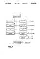
- FIG. 1is a schematic, block diagram representation of the display transducer adapter of the present invention connected to a digital relay which is, in turn, connected to a three phase power system.
- FIG. 2is a view of the rear input panel of the display transducer adapter of the present invention.
- FIG. 3is a graphic representation of the scaling of the analog outputs of the display transducer adapter of the present invention.
- FIG. 4is a block diagram representation of the circuitry of the display transducer adapter of the present invention.
- FIG. 5is a view of the front display panel of the display transducer adapter of the present invention.
- FIGS. 6A-6Eare electrical schematic diagrams illustrating circuitry of the display transducer adapter of the present invention.
- FIG. 1shows a display transducer adapter (DTA) 30, a digital relay 32, a two way communication bus 34, and a three phase power system 36 (lines A, B, C).
- the DTA 30is electrically coupled by the communication bus 34, which may be a single electrical cable, to digital relay 32.
- the relayis connected across the lines of three phase power system 36.
- the DTA 30provides access to the following relay data: fault, meter, and status information. New faults are captured, stored and displayed by DTA 30 as they occur. Meter information is displayed and continuously updated on demand. Relay self-test failures and other status warnings are automatically displayed with a visual alert, and status information is displayed on demand for logging purposes. This blend of display features permits both transmission line monitoring and verification and relay system functionality at a glance.
- the information available from DTA 30may be displayed automatically or in response to a user request via switches on the front panel of the DTA (see FIG. 5).
- Some user requests for datarequire on demand information from relay 32. If the user requests meter data by pressing the appropriate switch on the front panel of the DTA, the DTA requests the data from the relay by sending an appropriate character string, such as METER ⁇ CR>, to the relay via the communications link 34 between the DTA and the relay.
- the requested informationis formatted and stored as it is delivered by the relay, and then displayed when complete, as will be discussed in more detail below. Indeed, all fault, meter and status information from the relay are parsed, categorized and stored by DTA 30 as they are generated. These data are then formatted, scaled and delivered to the display, transducer outputs and/or contact outputs of DTA 30, as discussed below.
- the rear input panel of DTA 30includes: three serial or communication ports 40, 41 and 42 (Port 1, Port 2 and Port 2A); an analog output 43; six type A relay contacts A1-A6; a type B relay contact for an alarm (ALRM); and two programmable isolator inputs ISO1 and ISO2.
- the communications portsprovide RS-232-C serial communications interfaces (nine-pin connectors).
- the serial data formatis: 8 data bits, 2 stop bits and no parity.
- the baud rates of the portsare set with jumpers which are accessible by removing the top cover (not shown) of DTA 30. Available rates are: 300, 600, 1200, 2400, 4800, and 9600.
- Communications port 40may be connected to a computer terminal, a CRT and/or modem for changing the analog output scaling and other DTA settings.
- Port 41(Port 2) provides links to the relay for communications and D.C. power. It should be connected to the relay automatic message port.
- Port 42(Port 2A) may be connected to port 41 via a null modem, and may be utilized for monitoring of port 41 and alternate power supply configurations.
- DTA 30may be powered by a supplemental power supply via communications port 41, and links to the relay for data are then provided via port 42. Since power is not being drawn from the relay, the cabling to the relay may be quite long, and, indeed, it may be further extended using, for example, a short-haul modem or similar isolating device.
- DTA 30is equipped with eight programmable transducer channels at which an analog output signal is available. These signals are available from the rear panel at analog output 43 in voltage (0-5 v) and current (0-1 mA) form. A separate return to ground is also provided for each channel. These signals may be presented at the rear panel through a female 25-pin "D" connector. For systems requiring screw terminal connections, an optional adapter board may be used, which breaks a female 25-pin "D” connector out into screw terminals.
- the signals at analog output 43are assigned pin numbers as shown in Chart B.
- Each analog output channelmay be preferentially selected by the user as to function, i.e. as to which system parameter is available at which channel.
- each channelmay be selected to be proportional to one of the following: phase-to-phase voltage, phase-to-neutral voltage, phase current, phase-to-phase current, real power, reactive power, or fault location. All permutations of phase quantities are supported.
- the ranges of all output channelsare also independently selectable by the user.
- the analog outputsare scaled as shown in FIG. 3 where X is any phase, phase-to-phase, or phase-to-neutral quantity, real or reactive power, or fault location.
- the dedication of transducer channels to meter quantities and the scaled rangeare user settable parameters.
- the versatility afforded by the featuresallows utilization of the DTA in a wide range of data acquisition and metering applications, reducing or eliminating entirely the need for discrete transducers.
- the outputs of the six type A relay contacts A1-A6indicate fault conditions and acknowledge reset commands.
- the additional type B relay contact ALRMis provided to indicate a self-test failure or other alarm condition. All contact outputs are dedicated and are not programmable.
- the contact assignments and signal descriptionsare as shown in Chart C:
- a suitable time intervalcontrols updating of contact outputs A1-A5 and any analog outputs dedicated to fault location.
- LOCK secondsafter a fault, the outputs are not affected by subsequent faults. This feature may be used to avoid replacement of accurate fault information by less accurate data (as may occur during reclosing operations).
- the RST ACK outputcloses for one minute. During this interval, the output is retriggerable, and remains closed for one minute after the most recent retriggering.
- the programmable isolator inputs ISO1 and ISO2are provided for control of transducer and contact output data from a remote system.
- ISO1the RESET input, clears any analog channels set to indicate fault location, and clears contact outputs A1-A5. After the output quantities are cleared, the RST ACK contact output A6 is triggered. This input is rising-edge sensitive.
- ISO2may be reserved for future applications.
- the main components of the circuitry of DTA 30is shown in FIG. 4 in block diagram format. As discussed above, they include: serial ports 40-42, contact inputs ISO1 and ISO2, analog outputs 43, and relay outputs A1-A6 and ALRM.
- a display module 52(see also FIG. 5) is provided for the display of information.
- a microprocessorsuch as a Motorola MC6809, controls the operation of DTA 30.
- the circuitryalso includes a random-access memory (RAM) 46, a read-only memory (ROM) 47, and an electrically-erasable programmable ROM (EEPROM) 48.
- the RAM 46retains variables used in data processing and computations, while ROM 47 stores the program executed by the microprocessor.
- EEPROM 48is utilized to save settings such as those listed in Appendix A, discussed below.
- the data from the digital relayare read, parsed, categorized, stored, formatted, scaled, and delivered, according to the program stored in ROM 47 while those data are being held in RAM 46.
- Settings saved in EEPROM 48effect the scaling and other functions as shown in Appendix A.
- the front panel 50is arranged to provide the system operator with: fault, meter, and status information on demand.
- the front panel 50includes: a liquid crystal display 52 for displaying information; a scroll down button 53 and a scroll up button 54 for scrolling up and down the information displayed on display 52; a fault select switch 55 for displaying fault information on display 52; a meter select switch 56 for displaying meter information on display 52; and a status select switch 58 for displaying status information on display 52.
- a clear select switch 60is provided to clear the information displayed on display 52.
- Display 52is preferably a two-line, forty column, high contrast display. As noted, display modes and scrolling are controlled with the front panel switches. A switch is asserted by toggling upward until it clicks. The "scroll" switches 53 and 54 repeat if held in the asserted state. Faults, meter and status information displays are described below.
- the FAULTS modei.e. display of fault information
- the FAULTS modemay be entered in two ways: (1) pressing the faults switch 55; or (2) new faults reported by the relay 32 preempt all other display modes and place DTA 30 in the FAULTS mode.
- Assertion of faults switch 55allows viewing of the latest thirty validated faults as reported to DTA 30 by relay 32. The most recent two faults are the first displayed. If no faults have been captured since power up, the message "FAULT HISTORY EMPTY" is displayed.
- Faultsare numbered sequentially from the newest to the oldest; the most recent fault is assigned the number "1", with previous faults discarded as the fault history exceeds thirty lines in length.
- the contents of the displayare determined by the position of the display window 57 within the thirty fault history.
- Chart Dillustrates an example fault history, with the display window positioned to include the two most recent faults (as if the mode was just recently entered). As shown by Chart D, the display shows for each fault: the fault number (01), the date (01/02/88) and time (22:31:51.812) of the fault, the type of fault (1BG (line B to ground)), and the fault location (74.58 (miles)).
- DTA 30When a fault report is sent to DTA 30 from relay 32, it is first checked against a settable fault location window (see the below discussion of the SET command). If the fault lies within the window, the currently active display mode is preempted, and the DTA enters the FAULT's mode automatically. DTA 30 indicates the receipt of the new fault by annexing the line "NEW FAULT" to the top of the fault list in blinking characters, and the information pertaining to that fault is displayed.
- any transducer outputs(analog output 43) are programmed to present the faults location, these channels will be updated according to the rules outlined below in the discussion of the SET command.
- the contact outputs A1-A6also reflect fault information.
- the DTA 30remains in the FAULTS mode of operation until another display mode is selected. Also, if all new faults have been acknowledged, the FAULTS mode may be preempted by the status mode via detection of a relay status warning.
- the METER modei.e. display of meter information, is activated by assertion of the meter switch 56.
- display 52contains the information shown in Chart E.
- the top display linecontains the letter "V”, indicating that the next three display fields contain voltage data.
- the first fieldaccommodates the rms voltage Vab (233.1), the second field contains the rms voltage Vbc (232.8), and the third field shows the rms voltage Vca (232.9).
- the top display linealso contains the letter "P”, identifying the final field as real power (350.9).
- the bottom display linecontains the letter "I”, indicating that the next three display fields contain current data.
- the first fieldaccommodates the rms current Ia (994.0); the second field contains the rms current Ib (995.0); the third field shows the rms current Ic (994.0).
- the bottom displayalso contains the letter "Q" for displaying the reactive power (67.8).
- the DTA 30remains in the METER mode of operation until a new fault is reported.
- the modeis exited manually by assertion of clear switch 60, or another display mode is activated by assertion of the corresponding control. Additionally, the METER mode may be preempted by the STATUS mode via detection of a relay status warning.
- the scroll controls 53 and 54are not operative while in the METER mode.
- the STATUS modedisplay of status information
- the STATUS modemay be entered in two ways: (1) pressing the status control 58; or (2) detection of a relay status warning may preempt certain modes in favor of the STATUS mode under appropriate conditions.
- DTA 30Upon receipt of a relay status report, DTA 30 determines if the immediate mode may be preempted in its current state. If so, the STATUS mode is entered, with the line "RELAY STATUS WARNING" in blinking characters annexed to the beginning of the message. Assertion of any operative front-panel control acknowledges the condition, after which the STATUS mode functions as previously defined.
- the STATUS modeis exited automatically when a fault report is received, and may be exited manually by pressing the "clear", "meter”, or “faults" switches 60, 56 or 55.
- the STANDBY modemay be entered by pressing clear switch 60, and may be identified by the following display message: "SEL-DTA DISPLAY/TRANSDUCER ADAPTER".
- the DTA 30remains in this mode until (1) an active display mode is selected by assertion of an operative front-panel switch; (2) a relay status message is received; or (3) a fault is reported to the DTA by the relay. While in this mode, only the "faults”, “meter”, “status”, and “clear” switches 55, 56, 58, and 60 are operative.
- the function of clear switch 60depends upon the mode of the DTA. If the DTA is in any mode other than STANDBY, the mode is changed to STANDBY. If the DTA is already in STANDBY mode, the following operations occur: (1) the display module is tested for proper operation; if this test fails, an automatic status message is sent to port 40 (see FIG. 2); (2) while asserted, all elements of the display are actuated, allowing visual verification of proper display operation; and (3) upon release, the display is cleared and the DTA is returned to the STANDBY mode of operation.
- DTA 30also runs an assortment of self-tests that ensure reliable operation. Any change in self-test status results in the generation of a status report. All self-tests are run on power-up and after using the setting procedure. Afterwards, all self-tests except the display test are run at least every few minutes.
- the RAM 46(see FIG. 4) is periodically checked to ensure that each byte can be written to and read from correctly. There is no warning state for this test. If a problem is detected, a STATUS message is transmitted to port 40 which contains the socket designation of the affected RAM IC. ROM 47 is periodically tested by computing a checksum. If the computed value does not agree with the stored value, a ROM failure is declared. The STATUS message is also transmitted to port 40. Two images of the system settings are stored in nonvolatile memory. These are compared when the DTA is initially set, and periodically thereafter. Should the images ever disagree, the setting test fails and a STATUS message is transmitted to port 40. The display module 52 is tested when the instrument is powered up, and as described in the discussion of the STANDBY mode. If a display module failure is detected, the DTA sends an automatic status message to port 40.
- the communications protocolutilizes both hardware and software attributes.
- the hardware protocolis implemented in the control line functions RTS and CTS.
- a software protocol designed for manual and automatic communicationsis also provided. The elements of this protocol are discussed below.
- All commands received by DTA 30must be of the form: ⁇ command> ⁇ CR> or ⁇ command> ⁇ CRLF>.
- a command transmitted to DTA 30should consist of the command name, followed by either a carriage return or a carriage return and a line feed. (To use any command, only the first three characters need to be typed. Character case is not relevant.)
- All messages transmitted by DTA 30are of the following format:
- each messagebegins with the start-of-transmission character (ASCII 02), and ends with the end-of-transmission character (ASCII 03), and each line of the transmission is terminated by a carriage return and a line feed.
- DTA 30indicates the volume of data in its receive-data buffer (part of RAM 46) using an XON/XOFF protocol. When this buffer drops below 1/4 full, the DTA 30 transmits XON (ASCII hex 11) and asserts the RTS output. When the buffer fills above 3/4 of capacity, the DTA transmits XOFF (ASCII hex 13). If the buffer reaches 95% full, the DTA unasserts the RTS output. Transmitting sources should monitor for the XOFF character to prevent overwriting of the DTA input buffer (part of RAM 46). Transmission should terminate at the end of the message being transmitted when XOFF is received and may be resumed when the XON character is received.
- An XON/XOFF proceduremay be used to control data transmission by DTA 30.
- the DTAreceives XOFF while transmitting, it responds by pausing until an XON character is received. If no message is being transmitted when XOFF is received, the DTA blocks transmission of any message that may be presented to its transmitting buffer (part of RAM 46). The message will be transmitted when the XON character is received.
- the CAN character(ASCII hex 18), received at any time, aborts a pending transmission. This is useful in terminating an unwanted transmission.
- the control characterscan be sent from most keyboards using the following keystrokes:
- control-Xhold down the control key, and press X
- the DTA 30When the power is first turned on, the DTA 30 is in Access Level 0, and honors only the ACCESS command. "Invalid command” or “Invalid access level” are the responses to any other entries. All commands except those that change settings are available at Access Level 1. Setting changes may be made only at Access Level 2.
- the instrumentWhen power is first applied, the instrument transmits the following message to port 40: "SEL-DTA Display/Transducer Adapter Date: mm/dd/yy Time: hh/mm/ss SEL-DTA". Commands consist of three or more characters. Only the first three characters of any command need be entered. Character case is not relevant for commands. For passwords, however, case is important. Items in square brackets [. . . ] are optional.
- Commandsmust be separated from the command by spaces, commas, semicolons, colons, or slashes. Commands may be entered any time after an appropriate prompt is received. Commands are entered through port 40 (See FIG. 2), to set the DTA. A computer terminal need not remain connected to the port. The commands available at various access levels are discussed below.
- ACCESSis used to gain access to the system.
- the DTA 30prompts for a Level 1 password before granting access. If three unsuccessful password entry attempts are made in a row, the alarm contact is pulsed closed for one second. If the alarm is connected to a monitoring system, such as Substation System Control and Data Acquisition ("SCADA"), this feature can be used to alert operations personnel that possible unauthorized access is being attempted.
- SCADASubstation System Control and Data Acquisition
- type DATE ⁇ CR>To read the date kept by the internal calendar/clock, type DATE ⁇ CR>. To set the date, type DATE mm/dd/yy ⁇ CR>.
- Executing the QUIT commandreturns control to Access Level 0 from either Access Level 1 or 2, and displays the instrument identification, and the date and time when QUIT is executed. This command is utilized when communications with DTA 30 are completed, so that unauthorized access is avoided.
- the DTAalso automatically executes the STATUS command whenever a self-test enters a warning or a failure state, causing the STATUS report to be transmitted out of serial communications port 40.
- TIMETo read the internal clock enter TIME ⁇ CR>. To set the clock enter TIME followed by the desired setting. A quartz crystal oscillator provides the time base for the internal clock.
- the setting procedureconsists of answering prompting messages with new data, or indicating no change by simply responding with ⁇ CR>. Once all data are provided, the new settings are displayed, and a prompt issued requesting approval to enable DTA 30 with the new settings. Error messages indicate when the entered data are out of range.
- An example SET command displayfollows and is shown in attached Appendix A.
- the TIME1 settingcontrols the timeout interval of communications port 40 (see FIG. 2).
- LOCKspecifies the time after a fault during which analog and contact output changes will be suppressed. If, for example, a fault was immediately followed by two reclose faults within 4.167 seconds, only the first fault would affect the analog and contact outputs (given the example LOCK setting of 1000 quarter cycles).
- the RESET settingcontrols the amount of time after a fault at which the analog and contact outputs will automatically reset. The example setting tells DTA 30 to wait for two minutes before resetting the outputs. A setting of 0 specifies no automatic reset.
- Settings MINW and MAXWspecify the fault location window. Faults with locations outside this window will be ignored by DTA 30. For example settings, a fault with a location of 75.34 miles would be captured, stored, displayed, and presented at the contact and analog outputs. A reverse fault with location -34.45 miles would not be processed by the DTA; all outputs would be unaffected.
- QUA1-QUA8control the class of data appearing at the transducer outputs. Available quantities are voltages, currents, watts, vars, and fault location. In the example setting (see Appendix A), QUA1 is set to "VAB", indicating that transducer channel 1 will reflect the voltage as measured from phase A to phase B.
- MIN1-MIN8 and MAX1-MAX8reflect the measured quantities corresponding to 0 V (0 mA) and 5 V (1 mA), respectively. Values falling within the set range for a channel are scaled according to the equations: ##EQU1##
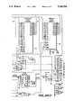
- FIGS. 6A-6EAn electrical schematic diagram of circuitry that may be utilized in DTA 30 is illustrated in FIGS. 6A-6E.
- the circuitryincludes microprocessor 45 (see also FIG. 4) connected in circuit with RAM 46, ROM 47 and EEPROM 48.
- the RAM 46may be implemented by means of high and low RAMS, and the ROM 47 by an EPROM.
- These circuit elementsparse, categorize and store the fault, meter and status information received from relay 32. This information is also available for display at display module 52 (see also FIG. 5).
- quartz crystal oscillator 62provides the time base.
- Port 1As shown in FIG. 6B, communication to the circuitry from, e.g. a computer terminal, is provided by means of Port 1 (see also FIG. 2). And as also discussed, Port 2 provides links to relay 32 for communications and power. Port 2A provides the link to relay 32 if a supplemental power supply is required. Low-energy, low voltage metal oxide varistors (MOVs) 64 and passive RC filters 66 are provided to protect the communication circuits. Switches S1-S6 correspond to switches 53-56, 58 and 60 on the front panel of DTA 30 (see FIG. 5).
- MOVsmetal oxide varistors
- Switches S1-S6correspond to switches 53-56, 58 and 60 on the front panel of DTA 30 (see FIG. 5).
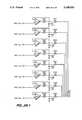
- FIGS. 6C and 6Dillustrate the analog output 43.
- a digital-to-analog converter 68is included in this portion of the circuitry for converting the digitized information into analog signals.
- the SET commandis provided for programming or selecting the particular function or parameter available at a selected analog output or channel. The ranges of these outputs may be selectively set by this method.
- the SET commandis part of the program stored in ROM 47. When the operator uses the SET command, microprocessor 45 accepts his configuration for the accepted quantities and ranges, and stores them in EEPROM 48.
- a surge network 70(FIG. 6D) is provided for protecting the circuit elements.
- FIG. 6Eshows relay contacts A1-A6 and ALRM (see also FIG. 2). Isolator inputs ISO1 and ISO2 are also shown.
- DTA 30offers a simple and economical on-line interface to a protective relay. Additionally, the programmable current and voltage transducers (analog outputs) permit integration of data acquisition and relaying capabilities, resulting in substantial cost and complexity savings over discrete systems employing conventional transducers. As discussed, new fault information and analog channel control are provided via relay contact outputs and isolator inputs, allowing easy interface to power system monitoring control equipment, such as SCADA systems. Additionally, for most applications, a single cable connection to the relay serial port satisfies all power and data requirements.
Landscapes
- Physics & Mathematics (AREA)
- General Physics & Mathematics (AREA)
- Remote Monitoring And Control Of Power-Distribution Networks (AREA)
Abstract
Description
CHART A ______________________________________ Wire Size Maximum Cable Length (AWG) (FEET) ______________________________________ 18 18 20 11 22 7.0 24 4.5 ______________________________________
CHART B ______________________________________ SIGNAL DESCRIPTION PIN NUMBER ______________________________________Voltage output 1 13Ground 1 25Current output 1 12Voltage output 2 11Ground 2 24Current output 2 10Voltage output 3 9Ground 3 23Current output 3 8Voltage output 4 7Ground 4 22Current output 4 6Voltage output 5 5Ground 5 21Current output 5 4Voltage output 6 3Ground 6 20Current output 6 2Voltage output 7 1Ground 7 19Current output 7 14Voltage output 8 15Ground 8 18Current output 8 16 ______________________________________
CHART C ______________________________________ Terminal Relay Block Contact Positions SignalDescription ______________________________________ A1 5,6 A The current fault involvesphase A A2 7,8 B The current fault involvesphase B A3 9,10 C The current fault involvesphase C A4 11,12 G The current fault involves13,14 FAULT A fault has occurred ground A5 15,16 RST ACK All fault-related analog and contact outputs are reset A6 17,18 ALARM An alarm condition exists ______________________________________ ALRM
CHART D ______________________________________ ##STR1## ##STR2## ______________________________________
CHART E ______________________________________ V: 233.1 232.8 232.9 P: 350.9 I: 994.0 995.0 994.0 Q: 67.8 ______________________________________
CHART F ______________________________________ DATE: 01/04/87 TIME: 08:50:30 OFFSET IP = 0 mV ______________________________________
______________________________________ <STX><MESSAGE LINE 1><CRLF> <MESSAGE LINE 2><CRLF> . . <LAST MESSAGE LINE><CRLF><PROMPT><ETX> ______________________________________
__________________________________________________________________________APPENDIX A EXAMPLE SET COMMAND DISPLAY __________________________________________________________________________=>>set CTRL-X cancels. Enter data, or RETURN for no change ID: SEL-DTA Display/Transducer Adapter PERMISSIBLE RANGE ? <lower,upper;step> TIME1:Port 1 timeout (min) = 0 ? <0,30;1> LOCK: Output lockout (q.c.) = 1000 ? <0,8000;1> RESET: Output timeout (min) = 2 ? <0,600;1> MINW: Min Fault Window = -10.0 ? <-100000,100000> MAXW: Max Fault Window = 100.0 ? <-100000,100000> Analogs (VA, VB, VC, VAB, VBC, VCA, IA, IB, IC, IAB, IBC, ICA, P, Q, FL) QUA1: Measured quantity = VAB ? <VA,FL> MIN1: Min Range = 0.0 ? <-100000,100000> MAX1: Max Range = 500.0 ? <-100000,100000> QUA2: Measured quantity = IA ? <VA,FL> MIN2: Min Range = 0.0 ? <-100000,100000> MAX2: Max Range = 1200.0 ? < -100000,100000> QUA3: Measured quantity = IB ? <VA,FL> MIN3: Min Range = 0.0 ? <-100000,100000> MAX3: Max Range = 1200.0 ? <-100000,100000> QUA4: Measured quantity = IC ? <VA,FL> MIN4: Min Range = 0.0 ? <-100000,100000> MAX4: Max Range = 1200.0 ? <-100000,100000> QUA5: Measured quantity = P ? <VA,FL> MIN5: Min Range = 0.0 ? <-100000,100000> MAX5: Max Range = -200.0 ? <-100000,100000> QUA6: Measured quantity = P ? <VA,FL> MIN6: Min Range = 0.0 ? <-100000,100000> MAX6: Max Range = 200.0 ? <-100000,100000> QUA7: Measured quantity = Q ? <VA,FL> MIN7: Min Range = 200.0 ? <-100000,100000> MAX7: Max Range = -200.0 ? <-100000,100000> QUA8: Measured quantity = FL ? <VA,FL> MIN8: Min Range = 0.0 ? < -100000,100000> MAX8: Max Range = 100.0 ? <-100000,100000> New settings for: SEL-DTA Display/Transducer Adapter TIME1 = 0 LOCK = 1000 RESET = 2 MINW = -10.0 MAXW = 100.0 QUA1 = VAB MIN1 = 0.0 MAX1 = 500.0 QUA2 = IA MIN2 = 0.0 MAX2 = 1200.0 QUA3 = IB MIN3 = 0.0 MAX3 = 1200.0 QUA4 = IC MIN4 = 0.0 MAX4 = 1200.0 QUA5 = P MIN5 = 0.0 MAX5 = 200.0 QUA6 = P MIN6 = 0.0 MAX6 = -200.0 QUA7 = Q MIN7 = -200.0 MAX7 = 200.0 QUA8 = FL MIN8 = 0.0 MAX8 = 100.0 OK (Y/N) ? y __________________________________________________________________________
Claims (16)
Priority Applications (1)
| Application Number | Priority Date | Filing Date | Title |
|---|---|---|---|
| US07/682,395US5160926A (en) | 1989-06-28 | 1991-04-04 | Display transducer apparatus |
Applications Claiming Priority (2)
| Application Number | Priority Date | Filing Date | Title |
|---|---|---|---|
| US37304089A | 1989-06-28 | 1989-06-28 | |
| US07/682,395US5160926A (en) | 1989-06-28 | 1991-04-04 | Display transducer apparatus |
Related Parent Applications (1)
| Application Number | Title | Priority Date | Filing Date |
|---|---|---|---|
| US37304089AContinuation | 1989-06-28 | 1989-06-28 |
Publications (1)
| Publication Number | Publication Date |
|---|---|
| US5160926Atrue US5160926A (en) | 1992-11-03 |
Family
ID=27006007
Family Applications (1)
| Application Number | Title | Priority Date | Filing Date |
|---|---|---|---|
| US07/682,395Expired - LifetimeUS5160926A (en) | 1989-06-28 | 1991-04-04 | Display transducer apparatus |
Country Status (1)
| Country | Link |
|---|---|
| US (1) | US5160926A (en) |
Cited By (77)
| Publication number | Priority date | Publication date | Assignee | Title |
|---|---|---|---|---|
| US5426589A (en)* | 1991-09-17 | 1995-06-20 | Honda Giken Kogyo Kabushiki Kaisha | Method of and apparatus for limiting electrical loads on an electric vehicle |
| US5650771A (en)* | 1995-04-25 | 1997-07-22 | Lee; Chung-Cheng | Electrical socket with monitoring unit for monitoring operating conditions |
| US5680324A (en)* | 1995-04-07 | 1997-10-21 | Schweitzer Engineering Laboratories, Inc. | Communications processor for electric power substations |
| US5742513A (en)* | 1996-05-15 | 1998-04-21 | Abb Power T&D Company Inc. | Methods and systems for automatic testing of a relay |
| US5796631A (en)* | 1997-02-10 | 1998-08-18 | Tempo Instrument, Inc. | Method and apparatus for monitoring and characterizing power quality, faults and other phenomena in network power systems |
| US5841964A (en)* | 1995-06-28 | 1998-11-24 | Canon Kabushiki Kaisha | Operating state management system |
| US5978481A (en)* | 1994-08-16 | 1999-11-02 | Intel Corporation | Modem compatible method and apparatus for encrypting data that is transparent to software applications |
| EP0991160A2 (en) | 1998-09-28 | 2000-04-05 | Siemens Energy & Automation, Inc. | Circuit breaker trip unit and method for real-time fault indication |
| US6088659A (en)* | 1997-09-11 | 2000-07-11 | Abb Power T&D Company Inc. | Automated meter reading system |
| US6294988B1 (en)* | 1998-04-28 | 2001-09-25 | Suzuki Motor Corporation | Engine management system |
| US6404348B1 (en) | 1999-02-11 | 2002-06-11 | Power Quality Consultants, Inc. | Modular power quality monitoring device |
| US20030184932A1 (en)* | 2002-04-02 | 2003-10-02 | Mcnally Christopher Wade | Electrical ground isolation and secondary failure reduction detection and isolation |
| US20030195357A1 (en)* | 2000-08-11 | 2003-10-16 | Wolfram Stuer | Ruthenium complexes containing carboids |
| US6700902B1 (en) | 1998-10-19 | 2004-03-02 | Elster Electricity, Llc | Method and system for improving wireless data packet delivery |
| US20040125532A1 (en)* | 2002-12-30 | 2004-07-01 | Schweitzer Edmund O. | Digital protective relay for power systems with operator-initiated record keeping capability |
| US6867707B1 (en) | 2002-04-24 | 2005-03-15 | Elster Electricity, Llc | Automated on-site meter registration confirmation using a portable, wireless computing device |
| US7046682B2 (en) | 1997-02-12 | 2006-05-16 | Elster Electricity, Llc. | Network-enabled, extensible metering system |
| US7102355B1 (en) | 2006-03-21 | 2006-09-05 | General Electric Company | Method, apparatus and computer-readable code for magnifying an incipient ground fault and enable quick detection of such fault |
| US20060208695A1 (en)* | 2005-03-21 | 2006-09-21 | Eveready Battery Company, Inc. | Direct current power supply |
| US7119713B2 (en) | 2002-06-27 | 2006-10-10 | Elster Electricity, Llc | Dynamic self-configuring metering network |
| US7126494B2 (en) | 1997-02-12 | 2006-10-24 | Elster Electricity, Llc | Remote access to electronic meters using a TCP/IP protocol suite |
| US7142106B2 (en) | 2004-06-15 | 2006-11-28 | Elster Electricity, Llc | System and method of visualizing network layout and performance characteristics in a wireless network |
| US20070013232A1 (en)* | 2002-04-02 | 2007-01-18 | Mcnally Christopher W | Method, System, and Computer Software Code for Detection and Isolation of Electrical Ground Failure and Secondary Failure |
| US7170425B2 (en) | 2004-09-24 | 2007-01-30 | Elster Electricity, Llc | System and method for creating multiple operating territories within a meter reading system |
| US7176807B2 (en) | 2004-09-24 | 2007-02-13 | Elster Electricity, Llc | System for automatically enforcing a demand reset in a fixed network of electricity meters |
| US7187906B2 (en) | 2004-04-26 | 2007-03-06 | Elster Electricity, Llc | Method and system for configurable qualification and registration in a fixed network automated meter reading system |
| US7227350B2 (en) | 2004-03-18 | 2007-06-05 | Elster Electricity, Llc | Bias technique for electric utility meter |
| US7239250B2 (en) | 2004-04-26 | 2007-07-03 | Elster Electricity, Llc | System and method for improved transmission of meter data |
| US7248057B1 (en) | 2006-03-21 | 2007-07-24 | General Electric Company | Method, apparatus and computer-readable code for detecting on the fly an incipient ground fault in an electrical propulsion system of a locomotive |
| US7262709B2 (en) | 2004-04-26 | 2007-08-28 | Elster Electricity, Llc | System and method for efficient configuration in a fixed network automated meter reading system |
| US20070229089A1 (en)* | 2006-03-21 | 2007-10-04 | Kumar Ajith K | Method, apparatus and computer-readable code for detecting an incipient ground fault in an electrical propulsion system |
| US20070229090A1 (en)* | 2006-03-21 | 2007-10-04 | Kumar Ajith K | Method, apparatus and computer-readable code for detecting an incipient ground fault in an electrical propulsion system |
| US20070229091A1 (en)* | 2006-03-21 | 2007-10-04 | Kumar Ajith K | Method, apparatus and computer-readable code for detecting an incipient ground fault in an electrical propulsion system |
| US7308369B2 (en) | 2005-09-28 | 2007-12-11 | Elster Electricity Llc | Ensuring automatic season change demand resets in a mesh type network of telemetry devices |
| US7308370B2 (en) | 2005-03-22 | 2007-12-11 | Elster Electricity Llc | Using a fixed network wireless data collection system to improve utility responsiveness to power outages |
| US7312721B2 (en) | 2002-06-28 | 2007-12-25 | Elster Electricity, Llc | Data collector for an automated meter reading system |
| US7315162B2 (en) | 2004-03-18 | 2008-01-01 | Elster Electricity, Llc | Reducing power consumption of electrical meters |
| US7327998B2 (en) | 2004-12-22 | 2008-02-05 | Elster Electricity, Llc | System and method of providing a geographic view of nodes in a wireless network |
| US20080125984A1 (en)* | 2006-09-25 | 2008-05-29 | Veselin Skendzic | Spatially Assisted Fault Reporting Method, System and Apparatus |
| US7427927B2 (en) | 2006-02-16 | 2008-09-23 | Elster Electricity, Llc | In-home display communicates with a fixed network meter reading system |
| US7495578B2 (en) | 2005-09-02 | 2009-02-24 | Elster Electricity, Llc | Multipurpose interface for an automated meter reading device |
| US7545285B2 (en) | 2006-02-16 | 2009-06-09 | Elster Electricity, Llc | Load control unit in communication with a fixed network meter reading system |
| US20090254655A1 (en)* | 2008-04-04 | 2009-10-08 | Beau Kidwell | Generation and Control of Network Events and Conversion to SCADA Protocol Data Types |
| US7702594B2 (en) | 2004-09-24 | 2010-04-20 | Elster Electricity, Llc | System and method for automated configuration of meters |
| US7742430B2 (en) | 2004-09-24 | 2010-06-22 | Elster Electricity, Llc | System for automated management of spontaneous node migration in a distributed fixed wireless network |
| US20110035076A1 (en)* | 2009-08-10 | 2011-02-10 | Schweitzer Iii Edmund O | Electric power system automation using time coordinated instructions |
| US20110121989A1 (en)* | 2009-11-24 | 2011-05-26 | Symbol Technologies, Inc. | Remote sensing system |
| US8073384B2 (en) | 2006-12-14 | 2011-12-06 | Elster Electricity, Llc | Optimization of redundancy and throughput in an automated meter data collection system using a wireless network |
| US8203463B2 (en) | 2009-02-13 | 2012-06-19 | Elster Electricity Llc | Wakeup and interrogation of meter-reading devices using licensed narrowband and unlicensed wideband radio communication |
| US8320302B2 (en) | 2007-04-20 | 2012-11-27 | Elster Electricity, Llc | Over the air microcontroller flash memory updates |
| US20130116944A1 (en)* | 2009-03-05 | 2013-05-09 | Reason Tecnologia S A | Method and device to identify, record and store traveling wave heads in electric power systems |
| US8525692B2 (en) | 2008-06-13 | 2013-09-03 | Elster Solutions, Llc | Techniques for limiting demand from an electricity meter with an installed relay |
| US8929391B2 (en) | 2011-06-22 | 2015-01-06 | Schweitzer Engineering Laboratories, Inc. | Systems and methods for communications devices having multiple interfaces |
| US20150043697A1 (en)* | 2013-08-12 | 2015-02-12 | Schweitzer Engineering Laboratories, Inc. | Delay Compensation for Variable Cable Length |
| US9083503B2 (en) | 2013-05-02 | 2015-07-14 | Schweitzer Engineering Laboratories, Inc. | Synchronized clock event report |
| US9270442B2 (en) | 2014-04-29 | 2016-02-23 | Schweitzer Engineering Laboratories, Inc. | Time signal propagation delay correction |
| US9383735B2 (en) | 2012-10-04 | 2016-07-05 | Schweitzer Engineering Laboratories, Inc. | Distributed coordinated electric power delivery control system using component models |
| US9400330B2 (en) | 2012-10-19 | 2016-07-26 | Schweitzer Engineering Laboratories, Inc. | Manipulation resilient time distribution network |
| US9425652B2 (en) | 2014-06-16 | 2016-08-23 | Schweitzer Engineering Laboratories, Inc. | Adaptive holdover timing error estimation and correction |
| US9520860B2 (en) | 2012-10-19 | 2016-12-13 | Schweitzer Engineering Laboratories, Inc. | Time distribution switch |
| US9568516B2 (en) | 2014-09-23 | 2017-02-14 | Schweitzer Engineering Laboratories, Inc. | Determining status of electric power transmission lines in an electric power transmission system |
| US9590411B2 (en) | 2011-12-15 | 2017-03-07 | Schweitzer Engineering Laboratories, Inc. | Systems and methods for time synchronization of IEDs via radio link |
| US9599719B2 (en) | 2012-10-19 | 2017-03-21 | Schweitzer Engineering Laboratories, Inc. | Detection of manipulated satellite time signals |
| US9612132B2 (en) | 2007-12-26 | 2017-04-04 | Elster Solutions, Llc | Optimized data collection in a wireless fixed network metering system |
| US9709682B2 (en) | 2013-05-06 | 2017-07-18 | Schweitzer Engineering Laboratories, Inc. | Multi-constellation GNSS integrity check for detection of time signal manipulation |
| US9709680B2 (en) | 2012-09-08 | 2017-07-18 | Schweitzer Engineering Laboratories, Inc. | Quality of precision time sources |
| US9759816B2 (en) | 2013-01-11 | 2017-09-12 | Schweitzer Engineering Laboratories, Inc. | Multi-constellation GNSS integrity check for detection of time signal manipulation |
| US9760062B2 (en) | 2012-10-19 | 2017-09-12 | Schweitzer Engineering Laboratories, Inc. | Time distribution with multi-band antenna |
| US9813173B2 (en) | 2014-10-06 | 2017-11-07 | Schweitzer Engineering Laboratories, Inc. | Time signal verification and distribution |
| US10333301B2 (en) | 2017-05-04 | 2019-06-25 | Schweitzer Engineering Laboratories, Inc. | Transient simulation modeling for dynamic remedial action schemes using real-time protection setting updates |
| US10375108B2 (en) | 2015-12-30 | 2019-08-06 | Schweitzer Engineering Laboratories, Inc. | Time signal manipulation and spoofing detection based on a latency of a communication system |
| US10527732B2 (en) | 2017-02-09 | 2020-01-07 | Schweitzer Engineering Laboratories, Inc. | Verification of time sources |
| US10819727B2 (en) | 2018-10-15 | 2020-10-27 | Schweitzer Engineering Laboratories, Inc. | Detecting and deterring network attacks |
| US10912104B2 (en) | 2019-02-01 | 2021-02-02 | Schweitzer Engineering Laboratories, Inc. | Interleaved, static time division multiple access (TDMA) for minimizing power usage in delay-sensitive applications |
| US10992134B2 (en) | 2019-05-10 | 2021-04-27 | Schweitzer Engineering Laboratories, Inc. | Load shedding system for both active and reactive power based on system perturbation |
| US11630424B2 (en) | 2018-07-13 | 2023-04-18 | Schweitzer Engineering Laboratories, Inc. | Time signal manipulation detection using remotely managed time |
| US11962140B2 (en) | 2021-10-25 | 2024-04-16 | Schweitzer Engineering Laboratories, Inc. | Coordination of protective elements in an electric power system |
Citations (12)
| Publication number | Priority date | Publication date | Assignee | Title |
|---|---|---|---|---|
| US3778801A (en)* | 1970-04-10 | 1973-12-11 | J Nudelmont | Apparatus for indicating voltage presence, phase sequence, voltage magnitude, ground faults, etc. in an electrical power distribution system |
| US4077061A (en)* | 1977-03-25 | 1978-02-28 | Westinghouse Electric Corporation | Digital processing and calculating AC electric energy metering system |
| WO1983003011A1 (en)* | 1982-02-25 | 1983-09-01 | Scientific Columbus Inc | Multi-function electricity metering transducer |
| US4420805A (en)* | 1980-05-20 | 1983-12-13 | Tokyo Shibaura Denki Kabushiki Kaisha | Protective relaying system |
| US4581705A (en)* | 1983-01-28 | 1986-04-08 | Cooper Industries, Inc. | Method and machine for metering electric parameters |
| US4608648A (en)* | 1984-04-09 | 1986-08-26 | Mitsubishi Denki Kabushiki Kaisha | Data display system |
| US4689570A (en)* | 1984-04-26 | 1987-08-25 | Mitsubishi Denki Kabushiki Kaisha | Digital protective relay monitoring system |
| US4788619A (en)* | 1987-04-24 | 1988-11-29 | Basler Electric Company | Protective relays and methods |
| US4789824A (en)* | 1986-06-20 | 1988-12-06 | Brown, Boveri & Cie Ag | Digital measuring instrument for displaying a measured value that varies over time |
| US4801937A (en)* | 1986-06-16 | 1989-01-31 | Fernandes Roosevelt A | Line mounted apparatus for remote measurement of power system or environmental parameters beyond line-of-site distanc |
| US4862142A (en)* | 1987-10-26 | 1989-08-29 | Knight Eldon L | Circuit with memory for detecting intermittent changes in resistance, current, voltage, continuity, power interruption, light, and temperature |
| US4868704A (en)* | 1988-11-14 | 1989-09-19 | General Electric Company | Apparatus for providing distance protection and distance measurement for a high voltage transmission line |
- 1991
- 1991-04-04USUS07/682,395patent/US5160926A/ennot_activeExpired - Lifetime
Patent Citations (12)
| Publication number | Priority date | Publication date | Assignee | Title |
|---|---|---|---|---|
| US3778801A (en)* | 1970-04-10 | 1973-12-11 | J Nudelmont | Apparatus for indicating voltage presence, phase sequence, voltage magnitude, ground faults, etc. in an electrical power distribution system |
| US4077061A (en)* | 1977-03-25 | 1978-02-28 | Westinghouse Electric Corporation | Digital processing and calculating AC electric energy metering system |
| US4420805A (en)* | 1980-05-20 | 1983-12-13 | Tokyo Shibaura Denki Kabushiki Kaisha | Protective relaying system |
| WO1983003011A1 (en)* | 1982-02-25 | 1983-09-01 | Scientific Columbus Inc | Multi-function electricity metering transducer |
| US4581705A (en)* | 1983-01-28 | 1986-04-08 | Cooper Industries, Inc. | Method and machine for metering electric parameters |
| US4608648A (en)* | 1984-04-09 | 1986-08-26 | Mitsubishi Denki Kabushiki Kaisha | Data display system |
| US4689570A (en)* | 1984-04-26 | 1987-08-25 | Mitsubishi Denki Kabushiki Kaisha | Digital protective relay monitoring system |
| US4801937A (en)* | 1986-06-16 | 1989-01-31 | Fernandes Roosevelt A | Line mounted apparatus for remote measurement of power system or environmental parameters beyond line-of-site distanc |
| US4789824A (en)* | 1986-06-20 | 1988-12-06 | Brown, Boveri & Cie Ag | Digital measuring instrument for displaying a measured value that varies over time |
| US4788619A (en)* | 1987-04-24 | 1988-11-29 | Basler Electric Company | Protective relays and methods |
| US4862142A (en)* | 1987-10-26 | 1989-08-29 | Knight Eldon L | Circuit with memory for detecting intermittent changes in resistance, current, voltage, continuity, power interruption, light, and temperature |
| US4868704A (en)* | 1988-11-14 | 1989-09-19 | General Electric Company | Apparatus for providing distance protection and distance measurement for a high voltage transmission line |
Cited By (104)
| Publication number | Priority date | Publication date | Assignee | Title |
|---|---|---|---|---|
| US5426589A (en)* | 1991-09-17 | 1995-06-20 | Honda Giken Kogyo Kabushiki Kaisha | Method of and apparatus for limiting electrical loads on an electric vehicle |
| US5978481A (en)* | 1994-08-16 | 1999-11-02 | Intel Corporation | Modem compatible method and apparatus for encrypting data that is transparent to software applications |
| USRE40569E1 (en)* | 1995-04-07 | 2008-11-11 | Schweitzer Engineering Laboratories, Inc. | Communications processor for electric power substations |
| US5680324A (en)* | 1995-04-07 | 1997-10-21 | Schweitzer Engineering Laboratories, Inc. | Communications processor for electric power substations |
| US5650771A (en)* | 1995-04-25 | 1997-07-22 | Lee; Chung-Cheng | Electrical socket with monitoring unit for monitoring operating conditions |
| US5841964A (en)* | 1995-06-28 | 1998-11-24 | Canon Kabushiki Kaisha | Operating state management system |
| US5742513A (en)* | 1996-05-15 | 1998-04-21 | Abb Power T&D Company Inc. | Methods and systems for automatic testing of a relay |
| US5796631A (en)* | 1997-02-10 | 1998-08-18 | Tempo Instrument, Inc. | Method and apparatus for monitoring and characterizing power quality, faults and other phenomena in network power systems |
| US7505453B2 (en) | 1997-02-12 | 2009-03-17 | Elster Electricity, Llc | Network-enabled, extensible metering system |
| US7046682B2 (en) | 1997-02-12 | 2006-05-16 | Elster Electricity, Llc. | Network-enabled, extensible metering system |
| US7126494B2 (en) | 1997-02-12 | 2006-10-24 | Elster Electricity, Llc | Remote access to electronic meters using a TCP/IP protocol suite |
| US6088659A (en)* | 1997-09-11 | 2000-07-11 | Abb Power T&D Company Inc. | Automated meter reading system |
| US6294988B1 (en)* | 1998-04-28 | 2001-09-25 | Suzuki Motor Corporation | Engine management system |
| EP0991160A2 (en) | 1998-09-28 | 2000-04-05 | Siemens Energy & Automation, Inc. | Circuit breaker trip unit and method for real-time fault indication |
| EP0991160A3 (en)* | 1998-09-28 | 2003-01-08 | Siemens Energy & Automation, Inc. | Circuit breaker trip unit and method for real-time fault indication |
| US6700902B1 (en) | 1998-10-19 | 2004-03-02 | Elster Electricity, Llc | Method and system for improving wireless data packet delivery |
| US6404348B1 (en) | 1999-02-11 | 2002-06-11 | Power Quality Consultants, Inc. | Modular power quality monitoring device |
| US20030195357A1 (en)* | 2000-08-11 | 2003-10-16 | Wolfram Stuer | Ruthenium complexes containing carboids |
| US7035065B2 (en)* | 2002-04-02 | 2006-04-25 | General Electric Company | Electrical ground isolation and secondary failure reduction detection and isolation |
| US20030184932A1 (en)* | 2002-04-02 | 2003-10-02 | Mcnally Christopher Wade | Electrical ground isolation and secondary failure reduction detection and isolation |
| US20060181821A1 (en)* | 2002-04-02 | 2006-08-17 | General Electric Company | Electrical ground isolation and secondary failure reduction detection and isolation |
| US7746604B2 (en) | 2002-04-02 | 2010-06-29 | General Electric Company | Method, system, and computer software code for detection and isolation of electrical ground failure and secondary failure |
| US7256974B2 (en) | 2002-04-02 | 2007-08-14 | General Electric Company | Electrical ground isolation and secondary failure reduction detection and isolation |
| US20070013232A1 (en)* | 2002-04-02 | 2007-01-18 | Mcnally Christopher W | Method, System, and Computer Software Code for Detection and Isolation of Electrical Ground Failure and Secondary Failure |
| US6867707B1 (en) | 2002-04-24 | 2005-03-15 | Elster Electricity, Llc | Automated on-site meter registration confirmation using a portable, wireless computing device |
| US7119713B2 (en) | 2002-06-27 | 2006-10-10 | Elster Electricity, Llc | Dynamic self-configuring metering network |
| US7145474B2 (en) | 2002-06-27 | 2006-12-05 | Elster Electricity, Llc | Dynamic self-configuring metering network |
| US7301476B2 (en) | 2002-06-27 | 2007-11-27 | Elster Electricity, Llc | Dynamic self-configuring metering network |
| US7312721B2 (en) | 2002-06-28 | 2007-12-25 | Elster Electricity, Llc | Data collector for an automated meter reading system |
| US6920028B2 (en)* | 2002-12-30 | 2005-07-19 | Schweitzer Engineering Laboratories, Inc. | Digital protective relay for power systems with operator-initiated record keeping capability |
| US20040125532A1 (en)* | 2002-12-30 | 2004-07-01 | Schweitzer Edmund O. | Digital protective relay for power systems with operator-initiated record keeping capability |
| WO2004062055A3 (en)* | 2002-12-30 | 2005-04-21 | Schweitzer Engineering Lab Inc | Digital protective relay for power systems with operator-initiated record keeping capability |
| US7315162B2 (en) | 2004-03-18 | 2008-01-01 | Elster Electricity, Llc | Reducing power consumption of electrical meters |
| US7417420B2 (en) | 2004-03-18 | 2008-08-26 | Elster Electricity, Llc | Switch to bypass optical diode for reducing power consumption of electrical meters |
| US7227350B2 (en) | 2004-03-18 | 2007-06-05 | Elster Electricity, Llc | Bias technique for electric utility meter |
| US7262709B2 (en) | 2004-04-26 | 2007-08-28 | Elster Electricity, Llc | System and method for efficient configuration in a fixed network automated meter reading system |
| US7187906B2 (en) | 2004-04-26 | 2007-03-06 | Elster Electricity, Llc | Method and system for configurable qualification and registration in a fixed network automated meter reading system |
| US7239250B2 (en) | 2004-04-26 | 2007-07-03 | Elster Electricity, Llc | System and method for improved transmission of meter data |
| US7142106B2 (en) | 2004-06-15 | 2006-11-28 | Elster Electricity, Llc | System and method of visualizing network layout and performance characteristics in a wireless network |
| US7176807B2 (en) | 2004-09-24 | 2007-02-13 | Elster Electricity, Llc | System for automatically enforcing a demand reset in a fixed network of electricity meters |
| US7742430B2 (en) | 2004-09-24 | 2010-06-22 | Elster Electricity, Llc | System for automated management of spontaneous node migration in a distributed fixed wireless network |
| US7702594B2 (en) | 2004-09-24 | 2010-04-20 | Elster Electricity, Llc | System and method for automated configuration of meters |
| US7170425B2 (en) | 2004-09-24 | 2007-01-30 | Elster Electricity, Llc | System and method for creating multiple operating territories within a meter reading system |
| US7327998B2 (en) | 2004-12-22 | 2008-02-05 | Elster Electricity, Llc | System and method of providing a geographic view of nodes in a wireless network |
| US20060208695A1 (en)* | 2005-03-21 | 2006-09-21 | Eveready Battery Company, Inc. | Direct current power supply |
| US7308370B2 (en) | 2005-03-22 | 2007-12-11 | Elster Electricity Llc | Using a fixed network wireless data collection system to improve utility responsiveness to power outages |
| US7495578B2 (en) | 2005-09-02 | 2009-02-24 | Elster Electricity, Llc | Multipurpose interface for an automated meter reading device |
| US7308369B2 (en) | 2005-09-28 | 2007-12-11 | Elster Electricity Llc | Ensuring automatic season change demand resets in a mesh type network of telemetry devices |
| US7545285B2 (en) | 2006-02-16 | 2009-06-09 | Elster Electricity, Llc | Load control unit in communication with a fixed network meter reading system |
| US7427927B2 (en) | 2006-02-16 | 2008-09-23 | Elster Electricity, Llc | In-home display communicates with a fixed network meter reading system |
| US7498819B2 (en) | 2006-03-21 | 2009-03-03 | General Electric Company | Method, apparatus and computer-readable code for detecting an incipient ground fault in an electrical propulsion system |
| US20070229089A1 (en)* | 2006-03-21 | 2007-10-04 | Kumar Ajith K | Method, apparatus and computer-readable code for detecting an incipient ground fault in an electrical propulsion system |
| US7498820B2 (en) | 2006-03-21 | 2009-03-03 | General Electric Company | Method, apparatus and computer-readable code for detecting an incipient ground fault in an electrical propulsion system |
| US7501830B2 (en) | 2006-03-21 | 2009-03-10 | General Electric Company | Method, apparatus and computer-readable code for detecting an incipient ground fault in an electrical propulsion system |
| US20070229091A1 (en)* | 2006-03-21 | 2007-10-04 | Kumar Ajith K | Method, apparatus and computer-readable code for detecting an incipient ground fault in an electrical propulsion system |
| US20070229090A1 (en)* | 2006-03-21 | 2007-10-04 | Kumar Ajith K | Method, apparatus and computer-readable code for detecting an incipient ground fault in an electrical propulsion system |
| US7102355B1 (en) | 2006-03-21 | 2006-09-05 | General Electric Company | Method, apparatus and computer-readable code for magnifying an incipient ground fault and enable quick detection of such fault |
| US7248057B1 (en) | 2006-03-21 | 2007-07-24 | General Electric Company | Method, apparatus and computer-readable code for detecting on the fly an incipient ground fault in an electrical propulsion system of a locomotive |
| US20080125984A1 (en)* | 2006-09-25 | 2008-05-29 | Veselin Skendzic | Spatially Assisted Fault Reporting Method, System and Apparatus |
| US8073384B2 (en) | 2006-12-14 | 2011-12-06 | Elster Electricity, Llc | Optimization of redundancy and throughput in an automated meter data collection system using a wireless network |
| US8320302B2 (en) | 2007-04-20 | 2012-11-27 | Elster Electricity, Llc | Over the air microcontroller flash memory updates |
| US9612132B2 (en) | 2007-12-26 | 2017-04-04 | Elster Solutions, Llc | Optimized data collection in a wireless fixed network metering system |
| US20090254655A1 (en)* | 2008-04-04 | 2009-10-08 | Beau Kidwell | Generation and Control of Network Events and Conversion to SCADA Protocol Data Types |
| US9401839B2 (en) | 2008-04-04 | 2016-07-26 | Schweitzer Engineering Laboratories, Inc. | Generation and control of network events and conversion to SCADA protocol data types |
| US8525692B2 (en) | 2008-06-13 | 2013-09-03 | Elster Solutions, Llc | Techniques for limiting demand from an electricity meter with an installed relay |
| US8203463B2 (en) | 2009-02-13 | 2012-06-19 | Elster Electricity Llc | Wakeup and interrogation of meter-reading devices using licensed narrowband and unlicensed wideband radio communication |
| US20130116944A1 (en)* | 2009-03-05 | 2013-05-09 | Reason Tecnologia S A | Method and device to identify, record and store traveling wave heads in electric power systems |
| US9784783B2 (en)* | 2009-03-05 | 2017-10-10 | Reason Tecnologia S.A. | Method and device to identify, record and store traveling wave heads in electric power systems |
| US8682496B2 (en) | 2009-08-10 | 2014-03-25 | Schweitzer Engineering Laboratories Inc | Electric power system automation using time coordinated instructions |
| US8275485B2 (en) | 2009-08-10 | 2012-09-25 | Schweitzer Engineering Laboratories, Inc. | Electric power system automation using time coordinated instructions |
| US8275487B2 (en) | 2009-08-10 | 2012-09-25 | Schweitzer Engineering Laboratories, Inc. | Electric power system automation using time coordinated instructions |
| US20110035066A1 (en)* | 2009-08-10 | 2011-02-10 | Schweitzer Iii Edmund O | Electric power system automation using time coordinated instructions |
| US8275486B2 (en) | 2009-08-10 | 2012-09-25 | Schweitzer Engineering Laboratories, Inc. | Electric power system automation using time coordinated instructions |
| US20110035065A1 (en)* | 2009-08-10 | 2011-02-10 | Schweitzer Iii Edmund O | Electric power system automation using time coordinated instructions |
| US20110035076A1 (en)* | 2009-08-10 | 2011-02-10 | Schweitzer Iii Edmund O | Electric power system automation using time coordinated instructions |
| US20110121989A1 (en)* | 2009-11-24 | 2011-05-26 | Symbol Technologies, Inc. | Remote sensing system |
| US8242932B2 (en)* | 2009-11-24 | 2012-08-14 | Symbol Technologies, Inc. | Remote sensing system |
| US8929391B2 (en) | 2011-06-22 | 2015-01-06 | Schweitzer Engineering Laboratories, Inc. | Systems and methods for communications devices having multiple interfaces |
| US9590411B2 (en) | 2011-12-15 | 2017-03-07 | Schweitzer Engineering Laboratories, Inc. | Systems and methods for time synchronization of IEDs via radio link |
| US9709680B2 (en) | 2012-09-08 | 2017-07-18 | Schweitzer Engineering Laboratories, Inc. | Quality of precision time sources |
| US9383735B2 (en) | 2012-10-04 | 2016-07-05 | Schweitzer Engineering Laboratories, Inc. | Distributed coordinated electric power delivery control system using component models |
| US9760062B2 (en) | 2012-10-19 | 2017-09-12 | Schweitzer Engineering Laboratories, Inc. | Time distribution with multi-band antenna |
| US9520860B2 (en) | 2012-10-19 | 2016-12-13 | Schweitzer Engineering Laboratories, Inc. | Time distribution switch |
| US9400330B2 (en) | 2012-10-19 | 2016-07-26 | Schweitzer Engineering Laboratories, Inc. | Manipulation resilient time distribution network |
| US9599719B2 (en) | 2012-10-19 | 2017-03-21 | Schweitzer Engineering Laboratories, Inc. | Detection of manipulated satellite time signals |
| US10122487B2 (en) | 2012-10-19 | 2018-11-06 | Schweitzer Engineering Laboratories, Inc. | Time distribution switch |
| US9759816B2 (en) | 2013-01-11 | 2017-09-12 | Schweitzer Engineering Laboratories, Inc. | Multi-constellation GNSS integrity check for detection of time signal manipulation |
| US10288741B2 (en) | 2013-01-11 | 2019-05-14 | Schweitzer Engineering Laboratories, Inc. | Multi-constellation GNSS integrity check for detection of time signal manipulation |
| US9083503B2 (en) | 2013-05-02 | 2015-07-14 | Schweitzer Engineering Laboratories, Inc. | Synchronized clock event report |
| US9709682B2 (en) | 2013-05-06 | 2017-07-18 | Schweitzer Engineering Laboratories, Inc. | Multi-constellation GNSS integrity check for detection of time signal manipulation |
| US20150043697A1 (en)* | 2013-08-12 | 2015-02-12 | Schweitzer Engineering Laboratories, Inc. | Delay Compensation for Variable Cable Length |
| US9319100B2 (en)* | 2013-08-12 | 2016-04-19 | Schweitzer Engineering Laboratories, Inc. | Delay compensation for variable cable length |
| US9270442B2 (en) | 2014-04-29 | 2016-02-23 | Schweitzer Engineering Laboratories, Inc. | Time signal propagation delay correction |
| US9425652B2 (en) | 2014-06-16 | 2016-08-23 | Schweitzer Engineering Laboratories, Inc. | Adaptive holdover timing error estimation and correction |
| US9568516B2 (en) | 2014-09-23 | 2017-02-14 | Schweitzer Engineering Laboratories, Inc. | Determining status of electric power transmission lines in an electric power transmission system |
| US9813173B2 (en) | 2014-10-06 | 2017-11-07 | Schweitzer Engineering Laboratories, Inc. | Time signal verification and distribution |
| US10375108B2 (en) | 2015-12-30 | 2019-08-06 | Schweitzer Engineering Laboratories, Inc. | Time signal manipulation and spoofing detection based on a latency of a communication system |
| US10527732B2 (en) | 2017-02-09 | 2020-01-07 | Schweitzer Engineering Laboratories, Inc. | Verification of time sources |
| US10333301B2 (en) | 2017-05-04 | 2019-06-25 | Schweitzer Engineering Laboratories, Inc. | Transient simulation modeling for dynamic remedial action schemes using real-time protection setting updates |
| US11630424B2 (en) | 2018-07-13 | 2023-04-18 | Schweitzer Engineering Laboratories, Inc. | Time signal manipulation detection using remotely managed time |
| US10819727B2 (en) | 2018-10-15 | 2020-10-27 | Schweitzer Engineering Laboratories, Inc. | Detecting and deterring network attacks |
| US10912104B2 (en) | 2019-02-01 | 2021-02-02 | Schweitzer Engineering Laboratories, Inc. | Interleaved, static time division multiple access (TDMA) for minimizing power usage in delay-sensitive applications |
| US10992134B2 (en) | 2019-05-10 | 2021-04-27 | Schweitzer Engineering Laboratories, Inc. | Load shedding system for both active and reactive power based on system perturbation |
| US11962140B2 (en) | 2021-10-25 | 2024-04-16 | Schweitzer Engineering Laboratories, Inc. | Coordination of protective elements in an electric power system |
Similar Documents
| Publication | Publication Date | Title |
|---|---|---|
| US5160926A (en) | Display transducer apparatus | |
| US5963734A (en) | Method and apparatus for configuring an intelligent electronic device for use in supervisory control and data acquisition system verification | |
| US7158050B2 (en) | Revenue meter with fiber connection | |
| US5680324A (en) | Communications processor for electric power substations | |
| US20020032535A1 (en) | Energy information management method for use with a circuit breaker | |
| US5432705A (en) | Administrative computer and testing apparatus | |
| US6885307B2 (en) | Battery monitor | |
| EP1057132A2 (en) | Method of statistical analysis in an intelligent electronic device | |
| EP0433995B1 (en) | Remote instrument testing system | |
| WO1998010341A1 (en) | Control system monitor | |
| US4317199A (en) | Diagnostic extender test apparatus | |
| US5550460A (en) | Voltage regulator control system with multiple control programs | |
| JP2002525731A (en) | Man-machine interface for virtual lockout / tagout panel display | |
| KR20100117893A (en) | Current monitoring apparatus of distributing board | |
| CN107607903B (en) | Calibration method and device for electric energy metering equipment | |
| US5545974A (en) | Variamp oil temperature control | |
| CN212135265U (en) | Automatic temperature and humidity adjusting system | |
| CA2180611C (en) | Car space measurement apparatus | |
| WO2003071659A1 (en) | Power cut-off system with remote automatic alarm and meter reading service using power line communication network | |
| CN216595345U (en) | Anti-interference test system | |
| JP3515080B2 (en) | Power monitor and switchboard system using the same | |
| KR200288277Y1 (en) | Digital Ground Overvoltage relay | |
| KR200296782Y1 (en) | Digital power breaker | |
| US4675896A (en) | Remote monitoring apparatus | |
| JP2637354B2 (en) | Generator accident analysis device |
Legal Events
| Date | Code | Title | Description |
|---|---|---|---|
| STCF | Information on status: patent grant | Free format text:PATENTED CASE | |
| AS | Assignment | Owner name:SCHWEITZER, EDMUND O.,III, WASHINGTON Free format text:ASSIGNMENT OF ASSIGNORS INTEREST;ASSIGNOR:SCHWEITZER ENGINEERING LABS, INC.;REEL/FRAME:007232/0165 Effective date:19940901 Owner name:SCHWEITZER, MARY S., WASHINGTON Free format text:ASSIGNMENT OF ASSIGNORS INTEREST;ASSIGNOR:SCHWEITZER ENGINEERING LABS, INC.;REEL/FRAME:007232/0165 Effective date:19940901 | |
| FPAY | Fee payment | Year of fee payment:4 | |
| FPAY | Fee payment | Year of fee payment:8 | |
| AS | Assignment | Owner name:SCHWEITZER, ENGINEERING LABORATORIES, INC., WASHIN Free format text:ASSIGNMENT OF ASSIGNORS INTEREST;ASSIGNORS:SCHWEITZER, EDMUND O. III;SCHWEITZER, MARY S.;REEL/FRAME:011675/0067 Effective date:20010216 | |
| FEPP | Fee payment procedure | Free format text:PAT HOLDER NO LONGER CLAIMS SMALL ENTITY STATUS, ENTITY STATUS SET TO UNDISCOUNTED (ORIGINAL EVENT CODE: STOL); ENTITY STATUS OF PATENT OWNER: LARGE ENTITY | |
| REFU | Refund | Free format text:REFUND - 11.5 YR SURCHARGE- LATE PMT W/IN 6 MO, SMALL ENTITY (ORIGINAL EVENT CODE: R2556); ENTITY STATUS OF PATENT OWNER: LARGE ENTITY Free format text:REFUND - PAYMENT OF MAINTENANCE FEE, 12TH YR, SMALL ENTITY (ORIGINAL EVENT CODE: R2553); ENTITY STATUS OF PATENT OWNER: LARGE ENTITY | |
| FPAY | Fee payment | Year of fee payment:12 | |
| SULP | Surcharge for late payment | Year of fee payment:11 |