US5160559A - Method for forming a guide catheter tip bond - Google Patents
Method for forming a guide catheter tip bondDownload PDFInfo
- Publication number
- US5160559A US5160559AUS07/606,090US60609090AUS5160559AUS 5160559 AUS5160559 AUS 5160559AUS 60609090 AUS60609090 AUS 60609090AUS 5160559 AUS5160559 AUS 5160559A
- Authority
- US
- United States
- Prior art keywords
- tubular member
- deformable tip
- mating
- tip
- deformable
- Prior art date
- Legal status (The legal status is an assumption and is not a legal conclusion. Google has not performed a legal analysis and makes no representation as to the accuracy of the status listed.)
- Expired - Lifetime
Links
Images


Classifications
- A—HUMAN NECESSITIES
- A61—MEDICAL OR VETERINARY SCIENCE; HYGIENE
- A61M—DEVICES FOR INTRODUCING MEDIA INTO, OR ONTO, THE BODY; DEVICES FOR TRANSDUCING BODY MEDIA OR FOR TAKING MEDIA FROM THE BODY; DEVICES FOR PRODUCING OR ENDING SLEEP OR STUPOR
- A61M25/00—Catheters; Hollow probes
- A61M25/0009—Making of catheters or other medical or surgical tubes
- A61M25/001—Forming the tip of a catheter, e.g. bevelling process, join or taper
- B—PERFORMING OPERATIONS; TRANSPORTING
- B29—WORKING OF PLASTICS; WORKING OF SUBSTANCES IN A PLASTIC STATE IN GENERAL
- B29C—SHAPING OR JOINING OF PLASTICS; SHAPING OF MATERIAL IN A PLASTIC STATE, NOT OTHERWISE PROVIDED FOR; AFTER-TREATMENT OF THE SHAPED PRODUCTS, e.g. REPAIRING
- B29C65/00—Joining or sealing of preformed parts, e.g. welding of plastics materials; Apparatus therefor
- B29C65/02—Joining or sealing of preformed parts, e.g. welding of plastics materials; Apparatus therefor by heating, with or without pressure
- B29C65/06—Joining or sealing of preformed parts, e.g. welding of plastics materials; Apparatus therefor by heating, with or without pressure using friction, e.g. spin welding
- B29C65/0609—Joining or sealing of preformed parts, e.g. welding of plastics materials; Apparatus therefor by heating, with or without pressure using friction, e.g. spin welding characterised by the movement of the parts to be joined
- B29C65/0618—Linear
- B—PERFORMING OPERATIONS; TRANSPORTING
- B29—WORKING OF PLASTICS; WORKING OF SUBSTANCES IN A PLASTIC STATE IN GENERAL
- B29C—SHAPING OR JOINING OF PLASTICS; SHAPING OF MATERIAL IN A PLASTIC STATE, NOT OTHERWISE PROVIDED FOR; AFTER-TREATMENT OF THE SHAPED PRODUCTS, e.g. REPAIRING
- B29C65/00—Joining or sealing of preformed parts, e.g. welding of plastics materials; Apparatus therefor
- B29C65/02—Joining or sealing of preformed parts, e.g. welding of plastics materials; Apparatus therefor by heating, with or without pressure
- B29C65/14—Joining or sealing of preformed parts, e.g. welding of plastics materials; Apparatus therefor by heating, with or without pressure using wave energy, i.e. electromagnetic radiation, or particle radiation
- B—PERFORMING OPERATIONS; TRANSPORTING
- B29—WORKING OF PLASTICS; WORKING OF SUBSTANCES IN A PLASTIC STATE IN GENERAL
- B29C—SHAPING OR JOINING OF PLASTICS; SHAPING OF MATERIAL IN A PLASTIC STATE, NOT OTHERWISE PROVIDED FOR; AFTER-TREATMENT OF THE SHAPED PRODUCTS, e.g. REPAIRING
- B29C65/00—Joining or sealing of preformed parts, e.g. welding of plastics materials; Apparatus therefor
- B29C65/78—Means for handling the parts to be joined, e.g. for making containers or hollow articles, e.g. means for handling sheets, plates, web-like materials, tubular articles, hollow articles or elements to be joined therewith; Means for discharging the joined articles from the joining apparatus
- B29C65/7802—Positioning the parts to be joined, e.g. aligning, indexing or centring
- B—PERFORMING OPERATIONS; TRANSPORTING
- B29—WORKING OF PLASTICS; WORKING OF SUBSTANCES IN A PLASTIC STATE IN GENERAL
- B29C—SHAPING OR JOINING OF PLASTICS; SHAPING OF MATERIAL IN A PLASTIC STATE, NOT OTHERWISE PROVIDED FOR; AFTER-TREATMENT OF THE SHAPED PRODUCTS, e.g. REPAIRING
- B29C66/00—General aspects of processes or apparatus for joining preformed parts
- B29C66/01—General aspects dealing with the joint area or with the area to be joined
- B29C66/03—After-treatments in the joint area
- B29C66/034—Thermal after-treatments
- B29C66/0342—Cooling, e.g. transporting through welding and cooling zone
- B—PERFORMING OPERATIONS; TRANSPORTING
- B29—WORKING OF PLASTICS; WORKING OF SUBSTANCES IN A PLASTIC STATE IN GENERAL
- B29C—SHAPING OR JOINING OF PLASTICS; SHAPING OF MATERIAL IN A PLASTIC STATE, NOT OTHERWISE PROVIDED FOR; AFTER-TREATMENT OF THE SHAPED PRODUCTS, e.g. REPAIRING
- B29C66/00—General aspects of processes or apparatus for joining preformed parts
- B29C66/01—General aspects dealing with the joint area or with the area to be joined
- B29C66/05—Particular design of joint configurations
- B29C66/10—Particular design of joint configurations particular design of the joint cross-sections
- B29C66/11—Joint cross-sections comprising a single joint-segment, i.e. one of the parts to be joined comprising a single joint-segment in the joint cross-section
- B29C66/112—Single lapped joints
- B29C66/1122—Single lap to lap joints, i.e. overlap joints
- B—PERFORMING OPERATIONS; TRANSPORTING
- B29—WORKING OF PLASTICS; WORKING OF SUBSTANCES IN A PLASTIC STATE IN GENERAL
- B29C—SHAPING OR JOINING OF PLASTICS; SHAPING OF MATERIAL IN A PLASTIC STATE, NOT OTHERWISE PROVIDED FOR; AFTER-TREATMENT OF THE SHAPED PRODUCTS, e.g. REPAIRING
- B29C66/00—General aspects of processes or apparatus for joining preformed parts
- B29C66/01—General aspects dealing with the joint area or with the area to be joined
- B29C66/05—Particular design of joint configurations
- B29C66/10—Particular design of joint configurations particular design of the joint cross-sections
- B29C66/11—Joint cross-sections comprising a single joint-segment, i.e. one of the parts to be joined comprising a single joint-segment in the joint cross-section
- B29C66/114—Single butt joints
- B29C66/1142—Single butt to butt joints
- B—PERFORMING OPERATIONS; TRANSPORTING
- B29—WORKING OF PLASTICS; WORKING OF SUBSTANCES IN A PLASTIC STATE IN GENERAL
- B29C—SHAPING OR JOINING OF PLASTICS; SHAPING OF MATERIAL IN A PLASTIC STATE, NOT OTHERWISE PROVIDED FOR; AFTER-TREATMENT OF THE SHAPED PRODUCTS, e.g. REPAIRING
- B29C66/00—General aspects of processes or apparatus for joining preformed parts
- B29C66/01—General aspects dealing with the joint area or with the area to be joined
- B29C66/32—Measures for keeping the burr form under control; Avoiding burr formation; Shaping the burr
- B29C66/324—Avoiding burr formation
- B29C66/3242—Avoiding burr formation on the inside of a tubular or hollow article
- B—PERFORMING OPERATIONS; TRANSPORTING
- B29—WORKING OF PLASTICS; WORKING OF SUBSTANCES IN A PLASTIC STATE IN GENERAL
- B29C—SHAPING OR JOINING OF PLASTICS; SHAPING OF MATERIAL IN A PLASTIC STATE, NOT OTHERWISE PROVIDED FOR; AFTER-TREATMENT OF THE SHAPED PRODUCTS, e.g. REPAIRING
- B29C66/00—General aspects of processes or apparatus for joining preformed parts
- B29C66/50—General aspects of joining tubular articles; General aspects of joining long products, i.e. bars or profiled elements; General aspects of joining single elements to tubular articles, hollow articles or bars; General aspects of joining several hollow-preforms to form hollow or tubular articles
- B29C66/51—Joining tubular articles, profiled elements or bars; Joining single elements to tubular articles, hollow articles or bars; Joining several hollow-preforms to form hollow or tubular articles
- B29C66/52—Joining tubular articles, bars or profiled elements
- B29C66/522—Joining tubular articles
- B29C66/5221—Joining tubular articles for forming coaxial connections, i.e. the tubular articles to be joined forming a zero angle relative to each other
- B—PERFORMING OPERATIONS; TRANSPORTING
- B29—WORKING OF PLASTICS; WORKING OF SUBSTANCES IN A PLASTIC STATE IN GENERAL
- B29C—SHAPING OR JOINING OF PLASTICS; SHAPING OF MATERIAL IN A PLASTIC STATE, NOT OTHERWISE PROVIDED FOR; AFTER-TREATMENT OF THE SHAPED PRODUCTS, e.g. REPAIRING
- B29C66/00—General aspects of processes or apparatus for joining preformed parts
- B29C66/50—General aspects of joining tubular articles; General aspects of joining long products, i.e. bars or profiled elements; General aspects of joining single elements to tubular articles, hollow articles or bars; General aspects of joining several hollow-preforms to form hollow or tubular articles
- B29C66/51—Joining tubular articles, profiled elements or bars; Joining single elements to tubular articles, hollow articles or bars; Joining several hollow-preforms to form hollow or tubular articles
- B29C66/53—Joining single elements to tubular articles, hollow articles or bars
- B29C66/534—Joining single elements to open ends of tubular or hollow articles or to the ends of bars
- B29C66/5344—Joining single elements to open ends of tubular or hollow articles or to the ends of bars said single elements being substantially annular, i.e. of finite length, e.g. joining flanges to tube ends
- B—PERFORMING OPERATIONS; TRANSPORTING
- B29—WORKING OF PLASTICS; WORKING OF SUBSTANCES IN A PLASTIC STATE IN GENERAL
- B29C—SHAPING OR JOINING OF PLASTICS; SHAPING OF MATERIAL IN A PLASTIC STATE, NOT OTHERWISE PROVIDED FOR; AFTER-TREATMENT OF THE SHAPED PRODUCTS, e.g. REPAIRING
- B29C66/00—General aspects of processes or apparatus for joining preformed parts
- B29C66/50—General aspects of joining tubular articles; General aspects of joining long products, i.e. bars or profiled elements; General aspects of joining single elements to tubular articles, hollow articles or bars; General aspects of joining several hollow-preforms to form hollow or tubular articles
- B29C66/63—Internally supporting the article during joining
- B—PERFORMING OPERATIONS; TRANSPORTING
- B29—WORKING OF PLASTICS; WORKING OF SUBSTANCES IN A PLASTIC STATE IN GENERAL
- B29C—SHAPING OR JOINING OF PLASTICS; SHAPING OF MATERIAL IN A PLASTIC STATE, NOT OTHERWISE PROVIDED FOR; AFTER-TREATMENT OF THE SHAPED PRODUCTS, e.g. REPAIRING
- B29C66/00—General aspects of processes or apparatus for joining preformed parts
- B29C66/70—General aspects of processes or apparatus for joining preformed parts characterised by the composition, physical properties or the structure of the material of the parts to be joined; Joining with non-plastics material
- B29C66/73—General aspects of processes or apparatus for joining preformed parts characterised by the composition, physical properties or the structure of the material of the parts to be joined; Joining with non-plastics material characterised by the intensive physical properties of the material of the parts to be joined, by the optical properties of the material of the parts to be joined, by the extensive physical properties of the parts to be joined, by the state of the material of the parts to be joined or by the material of the parts to be joined being a thermoplastic or a thermoset
- B29C66/739—General aspects of processes or apparatus for joining preformed parts characterised by the composition, physical properties or the structure of the material of the parts to be joined; Joining with non-plastics material characterised by the intensive physical properties of the material of the parts to be joined, by the optical properties of the material of the parts to be joined, by the extensive physical properties of the parts to be joined, by the state of the material of the parts to be joined or by the material of the parts to be joined being a thermoplastic or a thermoset characterised by the material of the parts to be joined being a thermoplastic or a thermoset
- B29C66/7392—General aspects of processes or apparatus for joining preformed parts characterised by the composition, physical properties or the structure of the material of the parts to be joined; Joining with non-plastics material characterised by the intensive physical properties of the material of the parts to be joined, by the optical properties of the material of the parts to be joined, by the extensive physical properties of the parts to be joined, by the state of the material of the parts to be joined or by the material of the parts to be joined being a thermoplastic or a thermoset characterised by the material of the parts to be joined being a thermoplastic or a thermoset characterised by the material of at least one of the parts being a thermoplastic
- B—PERFORMING OPERATIONS; TRANSPORTING
- B29—WORKING OF PLASTICS; WORKING OF SUBSTANCES IN A PLASTIC STATE IN GENERAL
- B29C—SHAPING OR JOINING OF PLASTICS; SHAPING OF MATERIAL IN A PLASTIC STATE, NOT OTHERWISE PROVIDED FOR; AFTER-TREATMENT OF THE SHAPED PRODUCTS, e.g. REPAIRING
- B29C66/00—General aspects of processes or apparatus for joining preformed parts
- B29C66/90—Measuring or controlling the joining process
- B29C66/91—Measuring or controlling the joining process by measuring or controlling the temperature, the heat or the thermal flux
- B29C66/914—Measuring or controlling the joining process by measuring or controlling the temperature, the heat or the thermal flux by controlling or regulating the temperature, the heat or the thermal flux
- B29C66/9141—Measuring or controlling the joining process by measuring or controlling the temperature, the heat or the thermal flux by controlling or regulating the temperature, the heat or the thermal flux by controlling or regulating the temperature
- B29C66/91411—Measuring or controlling the joining process by measuring or controlling the temperature, the heat or the thermal flux by controlling or regulating the temperature, the heat or the thermal flux by controlling or regulating the temperature of the parts to be joined, e.g. the joining process taking the temperature of the parts to be joined into account
- B—PERFORMING OPERATIONS; TRANSPORTING
- B29—WORKING OF PLASTICS; WORKING OF SUBSTANCES IN A PLASTIC STATE IN GENERAL
- B29C—SHAPING OR JOINING OF PLASTICS; SHAPING OF MATERIAL IN A PLASTIC STATE, NOT OTHERWISE PROVIDED FOR; AFTER-TREATMENT OF THE SHAPED PRODUCTS, e.g. REPAIRING
- B29C66/00—General aspects of processes or apparatus for joining preformed parts
- B29C66/90—Measuring or controlling the joining process
- B29C66/91—Measuring or controlling the joining process by measuring or controlling the temperature, the heat or the thermal flux
- B29C66/919—Measuring or controlling the joining process by measuring or controlling the temperature, the heat or the thermal flux characterised by specific temperature, heat or thermal flux values or ranges
- A—HUMAN NECESSITIES
- A61—MEDICAL OR VETERINARY SCIENCE; HYGIENE
- A61M—DEVICES FOR INTRODUCING MEDIA INTO, OR ONTO, THE BODY; DEVICES FOR TRANSDUCING BODY MEDIA OR FOR TAKING MEDIA FROM THE BODY; DEVICES FOR PRODUCING OR ENDING SLEEP OR STUPOR
- A61M25/00—Catheters; Hollow probes
- A61M25/0067—Catheters; Hollow probes characterised by the distal end, e.g. tips
- A61M25/008—Strength or flexibility characteristics of the catheter tip
- A61M2025/0081—Soft tip
- A—HUMAN NECESSITIES
- A61—MEDICAL OR VETERINARY SCIENCE; HYGIENE
- A61M—DEVICES FOR INTRODUCING MEDIA INTO, OR ONTO, THE BODY; DEVICES FOR TRANSDUCING BODY MEDIA OR FOR TAKING MEDIA FROM THE BODY; DEVICES FOR PRODUCING OR ENDING SLEEP OR STUPOR
- A61M25/00—Catheters; Hollow probes
- A61M25/0043—Catheters; Hollow probes characterised by structural features
- A61M25/0054—Catheters; Hollow probes characterised by structural features with regions for increasing flexibility
- B—PERFORMING OPERATIONS; TRANSPORTING
- B29—WORKING OF PLASTICS; WORKING OF SUBSTANCES IN A PLASTIC STATE IN GENERAL
- B29C—SHAPING OR JOINING OF PLASTICS; SHAPING OF MATERIAL IN A PLASTIC STATE, NOT OTHERWISE PROVIDED FOR; AFTER-TREATMENT OF THE SHAPED PRODUCTS, e.g. REPAIRING
- B29C35/00—Heating, cooling or curing, e.g. crosslinking or vulcanising; Apparatus therefor
- B29C35/16—Cooling
- B29C2035/1616—Cooling using liquids
- B—PERFORMING OPERATIONS; TRANSPORTING
- B29—WORKING OF PLASTICS; WORKING OF SUBSTANCES IN A PLASTIC STATE IN GENERAL
- B29C—SHAPING OR JOINING OF PLASTICS; SHAPING OF MATERIAL IN A PLASTIC STATE, NOT OTHERWISE PROVIDED FOR; AFTER-TREATMENT OF THE SHAPED PRODUCTS, e.g. REPAIRING
- B29C65/00—Joining or sealing of preformed parts, e.g. welding of plastics materials; Apparatus therefor
- B29C65/02—Joining or sealing of preformed parts, e.g. welding of plastics materials; Apparatus therefor by heating, with or without pressure
- B29C65/14—Joining or sealing of preformed parts, e.g. welding of plastics materials; Apparatus therefor by heating, with or without pressure using wave energy, i.e. electromagnetic radiation, or particle radiation
- B29C65/1429—Joining or sealing of preformed parts, e.g. welding of plastics materials; Apparatus therefor by heating, with or without pressure using wave energy, i.e. electromagnetic radiation, or particle radiation characterised by the way of heating the interface
- B29C65/1435—Joining or sealing of preformed parts, e.g. welding of plastics materials; Apparatus therefor by heating, with or without pressure using wave energy, i.e. electromagnetic radiation, or particle radiation characterised by the way of heating the interface at least passing through one of the parts to be joined, i.e. transmission welding
- B—PERFORMING OPERATIONS; TRANSPORTING
- B29—WORKING OF PLASTICS; WORKING OF SUBSTANCES IN A PLASTIC STATE IN GENERAL
- B29C—SHAPING OR JOINING OF PLASTICS; SHAPING OF MATERIAL IN A PLASTIC STATE, NOT OTHERWISE PROVIDED FOR; AFTER-TREATMENT OF THE SHAPED PRODUCTS, e.g. REPAIRING
- B29C65/00—Joining or sealing of preformed parts, e.g. welding of plastics materials; Apparatus therefor
- B29C65/02—Joining or sealing of preformed parts, e.g. welding of plastics materials; Apparatus therefor by heating, with or without pressure
- B29C65/14—Joining or sealing of preformed parts, e.g. welding of plastics materials; Apparatus therefor by heating, with or without pressure using wave energy, i.e. electromagnetic radiation, or particle radiation
- B29C65/1477—Joining or sealing of preformed parts, e.g. welding of plastics materials; Apparatus therefor by heating, with or without pressure using wave energy, i.e. electromagnetic radiation, or particle radiation making use of an absorber or impact modifier
- B—PERFORMING OPERATIONS; TRANSPORTING
- B29—WORKING OF PLASTICS; WORKING OF SUBSTANCES IN A PLASTIC STATE IN GENERAL
- B29C—SHAPING OR JOINING OF PLASTICS; SHAPING OF MATERIAL IN A PLASTIC STATE, NOT OTHERWISE PROVIDED FOR; AFTER-TREATMENT OF THE SHAPED PRODUCTS, e.g. REPAIRING
- B29C66/00—General aspects of processes or apparatus for joining preformed parts
- B29C66/70—General aspects of processes or apparatus for joining preformed parts characterised by the composition, physical properties or the structure of the material of the parts to be joined; Joining with non-plastics material
- B29C66/73—General aspects of processes or apparatus for joining preformed parts characterised by the composition, physical properties or the structure of the material of the parts to be joined; Joining with non-plastics material characterised by the intensive physical properties of the material of the parts to be joined, by the optical properties of the material of the parts to be joined, by the extensive physical properties of the parts to be joined, by the state of the material of the parts to be joined or by the material of the parts to be joined being a thermoplastic or a thermoset
- B29C66/739—General aspects of processes or apparatus for joining preformed parts characterised by the composition, physical properties or the structure of the material of the parts to be joined; Joining with non-plastics material characterised by the intensive physical properties of the material of the parts to be joined, by the optical properties of the material of the parts to be joined, by the extensive physical properties of the parts to be joined, by the state of the material of the parts to be joined or by the material of the parts to be joined being a thermoplastic or a thermoset characterised by the material of the parts to be joined being a thermoplastic or a thermoset
- B29C66/7392—General aspects of processes or apparatus for joining preformed parts characterised by the composition, physical properties or the structure of the material of the parts to be joined; Joining with non-plastics material characterised by the intensive physical properties of the material of the parts to be joined, by the optical properties of the material of the parts to be joined, by the extensive physical properties of the parts to be joined, by the state of the material of the parts to be joined or by the material of the parts to be joined being a thermoplastic or a thermoset characterised by the material of the parts to be joined being a thermoplastic or a thermoset characterised by the material of at least one of the parts being a thermoplastic
- B29C66/73921—General aspects of processes or apparatus for joining preformed parts characterised by the composition, physical properties or the structure of the material of the parts to be joined; Joining with non-plastics material characterised by the intensive physical properties of the material of the parts to be joined, by the optical properties of the material of the parts to be joined, by the extensive physical properties of the parts to be joined, by the state of the material of the parts to be joined or by the material of the parts to be joined being a thermoplastic or a thermoset characterised by the material of the parts to be joined being a thermoplastic or a thermoset characterised by the material of at least one of the parts being a thermoplastic characterised by the materials of both parts being thermoplastics
- B—PERFORMING OPERATIONS; TRANSPORTING
- B29—WORKING OF PLASTICS; WORKING OF SUBSTANCES IN A PLASTIC STATE IN GENERAL
- B29C—SHAPING OR JOINING OF PLASTICS; SHAPING OF MATERIAL IN A PLASTIC STATE, NOT OTHERWISE PROVIDED FOR; AFTER-TREATMENT OF THE SHAPED PRODUCTS, e.g. REPAIRING
- B29C66/00—General aspects of processes or apparatus for joining preformed parts
- B29C66/90—Measuring or controlling the joining process
- B29C66/94—Measuring or controlling the joining process by measuring or controlling the time
- B29C66/949—Measuring or controlling the joining process by measuring or controlling the time characterised by specific time values or ranges
- B—PERFORMING OPERATIONS; TRANSPORTING
- B29—WORKING OF PLASTICS; WORKING OF SUBSTANCES IN A PLASTIC STATE IN GENERAL
- B29L—INDEXING SCHEME ASSOCIATED WITH SUBCLASS B29C, RELATING TO PARTICULAR ARTICLES
- B29L2023/00—Tubular articles
- B29L2023/005—Hoses, i.e. flexible
- B—PERFORMING OPERATIONS; TRANSPORTING
- B29—WORKING OF PLASTICS; WORKING OF SUBSTANCES IN A PLASTIC STATE IN GENERAL
- B29L—INDEXING SCHEME ASSOCIATED WITH SUBCLASS B29C, RELATING TO PARTICULAR ARTICLES
- B29L2031/00—Other particular articles
- B29L2031/753—Medical equipment; Accessories therefor
- B29L2031/7542—Catheters
Definitions
- the present inventionrelates to the field of angioplasty.
- the present inventionis a method for forming a guide catheter with a deformable tip.
- Angioplastyhas gained wide acceptance in recent years as an efficient and effective method for treating various types of vascular diseases.
- angioplastyis widely used for opening stenosis in the coronary arteries, although it is also used for treatment of stenosis in other parts of the vascular system.
- the most widely used form of angioplastymakes use of a guide catheter positioned within the vascular system of a patient.
- the distal end of the guide catheteris inserted into the femoral artery located in the groin of the patient and is pushed distally up through the vascular system until the distal end of the guide catheter is located in the ostium of the coronary artery.
- the proximal end of the guide catheterprotrudes outside of the patient's body to provide an entryway for subsequent insertion of additional angioplasty devices.
- the additional angioplasty devicesincludes dilatation catheters such as non-over-the-wire and over-the-wire balloon catheters.
- a method for forming a guide catheter with a deformable tipis needed that creates a lap joint tip bond exhibiting a large amount of surface area contact between the mating proximal end of the soft, deformable tip and the mating distal end of the main tubular member that makes up the guide catheter.
- the present inventionis a method of coupling a deformable first shaft member to a second shaft member by forming a high surface area connection zone between the first and second members.
- a mating proximal end of the deformable first shaft memberis set against a mating distal end of the second shaft member to form a butt joint.
- the butt jointis then softened to render the mating proximal and distal ends of the first and second shaft members flowable. While the mating ends are in a flowable state, the first and second shaft members are oscillated longitudinally along an axis defined by the longitudinal extent of the first and second shaft members.
- connection zoneis then allowed to solidify. This method results in a solidified connection zone with a large amount of surface area contact between the first and second shaft members. This large amount of surface area contact creates a bond that firmly couples the deformable first shaft member to the second shaft member.
- the first shaft memberis a soft, tubular, deformable tip and the second shaft member is a thermoplastic, tubular member.
- the method of the present inventionis used to secure the deformable tip to the tubular member to form a guide catheter with a deformable tip on its distal end.
- a rigid mandrelis inserted through the deformable tip such that a portion of the mandrel extends past the mating proximal end of the deformable tip.
- a sleeve memberis slid over the tip so that a first section of the sleeve member extends about the mating proximal end.
- the mating distal end of the tubular memberis then set against the proximal end of the deformable tip to thereby form the butt joint.
- a second section of the sleeve memberextends about the mating distal end of the tubular member, and the portion of the mandrel that extends past the mating proximal end of the tip is received within the mating distal end of the tubular member.
- the tubular memberis secured by a clamp member against movement relative to the deformable tip and heat from a heat source is applied to the deformable tip and tubular member to soften the mating proximal and distal ends at the butt joint. While heat is applied to the butt joint, the deformable tip is continuously forced against the tubular member by way of a pressure member to maintain contact between the mating proximal and distal ends. Softening of the butt joint renders the mating proximal end of the deformable tip and the mating distal end of the tubular member flowable.
- the butt jointis heated for 45 seconds at a temperature 430° F. while the pressure member maintains 10 p.s.i. of pressure against the deformable tip.
- the mandrel and the sleeve memberprevent the mating proximal and distal ends from bulging radially during softening of the butt joint.
- the tubular member and the deformable tipare longitudinally oscillated such that the mating distal and proximal ends flow into one another.
- the tubular member and deformable tipare oscillated for a period of three seconds. This procedure causes the formation of a lap joint (i.e., connection zone) wherein the mating proximal end of the deformable tip forms a tapered apex that extends proximally, and wherein the mating distal end of the tubular member forms a V-shaped groove that widens distally.
- the clampis disengaged from the tubular member, thereby releasing the tubular member and the pressure member is disengaged from the deformable tip, thereby removing the pressure at the tip.
- the lap jointis then allowed to solidify (i.e., cure) by cooling at room temperature.
- solidification of the lap jointcan be hastened by immersing the lap joint in an alcohol bath or by the use of a circulating air cooler.
- This method of forming a guide catheter with a deformable tipis relatively uncomplicated.
- the method of the present inventionproduces a lap joint tip bond exhibiting a large amount of surface area contact between the mating distal end of the tubular member and the mating proximal end of the deformable tip that make up the guide catheter. This large amount of surface area contact creates an extremely strong bond.
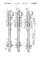
- FIG. 1is a perspective view of a guide catheter with a deformable tip bonded thereto in accordance with the method for forming a lap joint tip bond of the present invention, with some parts broken away to illustrate the lap joint tip bond.
- FIG. 2is a greatly enlarged perspective view of the lap joint tip bond shown in FIG. 1 with the components shown exploded for clarity only.
- FIG. 3is a diagrammatic sectional view of a mandrel inserted within the deformable tip and a sleeve member with the mandrel shown in full for clarity.
- FIG. 4is a diagrammatic sectional view similar to FIG. 3 showing the sleeve member positioned over the deformable tip and mandrel with a catheter member spaced therefrom.
- FIG. 5is a diagrammatic sectional view similar to FIG. 4 with the catheter member positioned within the sleeve and abutting the deformable tip.
- FIG. 6is a diagrammatic sectional view similar to FIG. 5 with the catheter member positioned within a clamping device and the deformable tip abutting a pressure member.
- FIG. 7is a perspective view showing the particulars of the pressure member shown in FIG. 6.
- FIG. 8is a diagrammatic sectional view similar to FIG. 6 showing the catheter member clamped in position with pressure being applied to the deformable tip by the pressure member and heat being applied to the abutting ends of the catheter member and the deformable tip.
- FIG. 9is a diagrammatic sectional view similar showing oscillation of the arrangement of FIG. 8 in accordance with the method for forming a lap joint tip bond of the present invention.
- FIG. 10is a perspective view of a cooling bath apparatus that may be used to increase the rate of curing of the lap joint tip bond formed by the method of the present invention.
- FIG. 11is a perspective view of a circulating air cooler that may alternately be used to increase the rate of curing of the lap joint tip bond formed by the method of the present invention.
- FIGS. 1 and 2A distal end of a guide catheter 10 formed in accordance with the method of the present invention is illustrated generally in FIGS. 1 and 2.
- the guide catheter 10includes a first shaft member, such as a soft thermoplastic or elastomeric, tubular, deformable tip 12 coupled at its mating proximal end 14 to a mating distal end 16 of a second shaft member, such as a thermoplastic or elastomeric, tubular member 18 (only a portion of which is shown in FIG. 1).
- the deformable tip 12is coupled to the tubular member 18 by way of a connection zone, such as a lap joint tip bond 20.
- the method of forming a guide catheter with a deformable tip in accordance with the present inventionproduces the lap joint tip bond 20, wherein the mating proximal end 14 of the deformable tip 12 forms a tapered apex 22 that extends proximally, and the mating distal end 16 of the tubular member 18 forms a V-shaped groove 24 that widens distally (see FIG. 2).
- a partial butt joint 26forms between a flat edge portion 28 of the mating proximal end 14 and a flat edge section 30 of the mating distal end 16 due to a coating of lubricous material 31, such as TEFLON, on an inner wall of the tubular member 18.
- the lap joint tip bond 20occurs as a blending of the materials from which the deformable tip 12 and tubular member 18 are formed.
- the lap joint tip bond 20 as illustrated in FIG. 1has been formed in accordance with the method of the present invention.
- FIG. 2is provided only for clarity and illustrates the lap joint tip bond 20 in an exploded condition. It is to be understood that the shape of the mating proximal 14 of the deformable tip 12 and the shape of the mating distal end 16 of the tubular member 18 shown in FIGS. 1 and 2 is produced only after the method of the present invention has been carried out.
- FIGS. 3-6, 8 and 9The method for forming the lap joint tip bond 20 is illustrated in FIGS. 3-6, 8 and 9.
- a rigid mandrel 32is first inserted through the deformable tip 12 such that a first portion 34 of the mandrel 32 extends past the mating proximal end 14 of the deformable tip 12.
- a sleeve member 36is slid over the deformable tip 12 so that a first section 38 of the sleeve member 36 extends about the mating proximal end 14.
- FIG. 3a rigid mandrel 32 is first inserted through the deformable tip 12 such that a first portion 34 of the mandrel 32 extends past the mating proximal end 14 of the deformable tip 12.
- a sleeve member 36is slid over the deformable tip 12 so that a first section 38 of the sleeve member 36 extends about the mating proximal end 14.
- the mating distal end 16 of the tubular member 18is then set (i.e., abutted) against the mating proximal end 14 of the deformable tip 12 to thereby form a butt joint 40.
- a second section 42 of the sleeve member 36extends about the mating distal end 16 of the tubular member 18, and the portion 34 of the mandrel 32 that extends past the mating proximal end 14 of the deformable tip 12 is received within the mating distal end 16 of the tubular member 18.
- the mating proximal end 14 of the deformable tip 12has a first flat end edge 44 and the mating distal end 16 of the tubular member 18 has a second flat end edge 46.
- the sleeve member 36 and the mandrel 32are sized to snugly receive or be snugly received, respectively, by the deformable tip 12 and tubular member 18.
- the combination of the tubular member 18, deformable tip 12, mandrel 32 and sleeve member 36is inserted between the clamp members 48 of a clamping device 50 such that the tubular member 18 is positioned between the clamp members 48.
- a distal end 52 of the deformable tip 12is received by a pressure member 54.
- the pressure member 54includes a through opening 56 extending from a proximal end 58 to a distal end 60 of the pressure member 54.
- the proximal end 58includes a pressure ledge 62 defined by a circular bottom wall 64 and a circumferential side wall 66.
- the pressure ledge 62is configured to receive the distal end 52 of the deformable tip 12, while the through opening 56 is configured to slidably receive a second portion 68 of the mandrel 32.
- the clamp members 48 of the clamping device 50are engaged with the tubular member 18 to secure the tubular member 18 against movement relative to the deformable tip 12.
- Heat(as represented by the wavy arrows 70) from a heat source 72 is applied to the deformable tip 12 and tubular member 18 to soften the mating proximal and distal ends 14 and 16 at the butt joint 40.
- Approximately two thirds of the heat from the heat source 72is directed to the mating distal end 16 of the tubular member 18, while the remaining one third of the heat is directed to the mating proximal end 14 of the deformable tip 12. This is done because the material used to form the tubular member 18 is stiffer then the material used to form the deformable tip 12. Therefore, more heat is required to soften the mating distal end 16 of the tubular member 18 then is required to soften the mating proximal end 14 of the deformable tip 12.
- the deformable tip 12While heat is applied to the butt joint 40, the deformable tip 12 is continuously forced against the tubular member 18 by way pressure exerted by the pressure member 54 (see FIG. 8). The pressure is exerted along a longitudinal axis 74 formed by the deformable tip 12 and tubular member 18. The pressure of the pressure member 54 maintains contact between the mating proximal end 14 of the deformable tip 12 and the mating distal end 16 of the tubular member 18. The heat from the heat source 72 and the pressure from the pressure member 54 act to soften the butt joint 40 and render the mating proximal end 14 of the deformable tip 12 and the mating distal end 16 of the tubular member 18 flowable.
- the tubular member 18 and deformable tip 12are both formed of polyether block amide and a radiopaque compound, except that the material of the deformable tip 12 has a lower durometer then the material of the tubular member 18. In other words, the tubular member 18 is stiffer than the deformable tip 12. In addition to the different durometers, the tubular member 18 also includes the coating of lubricous material 31 while the deformable tip 12 has no such coating.
- the tubular member 18has a durometer of 66 while the deformable tip 12 has a durometer of 37 and the butt joint 40 is heated by the heat source 72 for 45 seconds at a temperature 430° F. while the pressure member 54 maintains 10 p.s.i. of pressure against the distal end 52 of the deformable tip 12.
- the mandrel 32 and the sleeve member 44prevent the mating proximal and distal ends 14 and 16 from bulging radially during softening of the butt joint 40.
- the tubular member 18, the deformable tip 12, the mandrel 32, the sleeve member 44, the clamping device 50, and the pressure member 54are all oscillated (as represented by the double headed arrow 75) relative to the heat source 72 along the longitudinal axis 74 by a piston and cylinder device 76 (see FIG. 9).
- the longitudinal oscillationcauses the softened mating proximal and distal ends 14 and 16 to flow into one another.
- the tubular member 18 and the deformable tip 12are oscillated for a period of three seconds. This procedure causes the formation of the lap joint tip bond 20 (see FIGS.
- the mating proximal end 14 of the deformable tip 12forms the tapered apex 22 that extends proximally
- the mating distal end 16 of the tubular member 18forms the V-shaped groove 24 that widens distally
- the partial butt joint 26is formed between the flat edge portion 28 and the flat edge section 30 at the coating of lubricous material 31.
- the clamping device 50is disengaged from the tubular member 18, thereby releasing the tubular member 18, and the pressure member 54 is disengaged from the distal end 52 deformable tip 12, thereby removing the pressure at the deformable tip 12.
- the tubular member 18 with the deformable tip 12 coupled theretois then removed from the heat source 72 and the lap joint tip bond 20 is allowed to solidify (i.e., cure) by cooling at room temperature.
- the heat source 72remains on so that it is ready for the formation of subsequent lap joint tip bonds 20.
- formation of the guide catheter 10is complete.
- solidification of the lap joint tip bond 20can be hastened by immersing the lap joint tip bond 20 in a cooling bath 77 shown in FIG. 10.
- the cooling bath 77includes a bottom wall 78, a pair of spaced, upstanding sidewalls 80 and a pair of spaced, upstanding end walls 82.
- a guide catheter support plate 84is mounted to upper edges of the sidewalls 80 at a first end of the cooling bath 77.
- the support plate 84carries a plurality of guide catheter supports 86.
- a dunking plate 88is mounted to the upper edges of the sidewalls 80 spaced from the support plate 84.
- the cooling bath 76may be filled with a cooling substance such as an alcohol bath 90 which would hasten cooling of the lap joint tip bond 20 and thereby solidification of the lap joint tip bond 20 via evaporation of the alcohol bath 90.
- a guide catheter 20 with a lap joint tip bond 20 to be cooledis placed across one of the guide catheter supports 86 and beneath the dunking plate 88 which serves to maintain the lap joint tip bond 20 immersed in the alcohol bath 90.
- the lap joint tip bond 20is left in the alcohol bath 90 for a sufficient period of time to cool the lap joint tip bond 20.
- Solidification of the lap joint tip bond 20can be alternatively hastened by the use of a circulating air cooler 92, such as a VORTEC cooler as shown in FIG. 11.
- the circulating air cooler 92includes a bottom wall 93, a rear wall 94, a front wall 95, a pair of sidewalls 96 and a top wall 98.
- An air exhaust port 100extends out through the front wall 95.
- An air inlet tube 102extends through the exhaust port 100 and into the confines of the circulating air cooler 92.
- a guide catheter 10 with a lap joint tip bond 20 to be cooledis inserted into the cooler 92 through one of a plurality of slots 103 in the rear wall 94 such that the lap joint tip bond 20 is within the confines of the circulating air cooler 92.
- Air(as represented by the arrow 104) is forced into the confines of the circulating air cooler 92 through the air inlet tube 102.
- the aircirculates within the cooler 92 and is exhausted through the exhaust port 100 (as represented by the arrow 105).
- the circulating air within the circulating air cooler 92hastens cooling of the lap joint tip bond 20 and thereby solidification of the lap joint tip bond 20.
- the lap joint tip bond 20is left in the circulating air cooler 92 for a sufficient period of time to cool the lap joint tip bond 20.
- This method of forming a guide catheter 10 with a deformable tip 12is relatively uncomplicated.
- the method of the present inventionproduces a high strength lap joint tip bond 20 exhibiting a large amount of surface area contact between the mating distal end 16 of the tubular member 18 and the mating proximal end 14 of the deformable tip 12 that make up the guide catheter 10. This large amount of surface area contact creates an extremely strong bond.
Landscapes
- Engineering & Computer Science (AREA)
- Mechanical Engineering (AREA)
- Physics & Mathematics (AREA)
- Health & Medical Sciences (AREA)
- Thermal Sciences (AREA)
- Life Sciences & Earth Sciences (AREA)
- Anesthesiology (AREA)
- Pulmonology (AREA)
- Biophysics (AREA)
- Biomedical Technology (AREA)
- Heart & Thoracic Surgery (AREA)
- Hematology (AREA)
- Animal Behavior & Ethology (AREA)
- General Health & Medical Sciences (AREA)
- Public Health (AREA)
- Veterinary Medicine (AREA)
- Electromagnetism (AREA)
- Toxicology (AREA)
- Media Introduction/Drainage Providing Device (AREA)
Abstract
Description
Claims (11)
Priority Applications (3)
| Application Number | Priority Date | Filing Date | Title |
|---|---|---|---|
| US07/606,090US5160559A (en) | 1990-10-31 | 1990-10-31 | Method for forming a guide catheter tip bond |
| PCT/US1991/008064WO1992007607A1 (en) | 1990-10-31 | 1991-10-29 | Method for forming a guide catheter tip bond |
| AU89449/91AAU8944991A (en) | 1990-10-31 | 1991-10-29 | Method for forming a guide catheter tip bond |
Applications Claiming Priority (1)
| Application Number | Priority Date | Filing Date | Title |
|---|---|---|---|
| US07/606,090US5160559A (en) | 1990-10-31 | 1990-10-31 | Method for forming a guide catheter tip bond |
Publications (1)
| Publication Number | Publication Date |
|---|---|
| US5160559Atrue US5160559A (en) | 1992-11-03 |
Family
ID=24426487
Family Applications (1)
| Application Number | Title | Priority Date | Filing Date |
|---|---|---|---|
| US07/606,090Expired - LifetimeUS5160559A (en) | 1990-10-31 | 1990-10-31 | Method for forming a guide catheter tip bond |
Country Status (3)
| Country | Link |
|---|---|
| US (1) | US5160559A (en) |
| AU (1) | AU8944991A (en) |
| WO (1) | WO1992007607A1 (en) |
Cited By (72)
| Publication number | Priority date | Publication date | Assignee | Title |
|---|---|---|---|---|
| US5334169A (en)* | 1992-05-11 | 1994-08-02 | American Interventional Technologies, Inc. | Reinforced catheter with thin monolithic walls |
| US5358493A (en)* | 1993-02-18 | 1994-10-25 | Scimed Life Systems, Inc. | Vascular access catheter and methods for manufacture thereof |
| US5395336A (en)* | 1993-04-26 | 1995-03-07 | Mallinckrodt Medical, Inc. | Method for joining portions of a inflation/expansion catheter and a catheter so formed |
| US5445624A (en)* | 1994-01-21 | 1995-08-29 | Exonix Research Corporation | Catheter with progressively compliant tip |
| WO1995029726A1 (en)* | 1994-05-02 | 1995-11-09 | Medtronic, Inc. | Improved method of catheter segment attachment |
| US5509910A (en)* | 1994-05-02 | 1996-04-23 | Medtronic, Inc. | Method of soft tip attachment for thin walled catheters |
| US5531721A (en)* | 1992-07-02 | 1996-07-02 | Scimed Life Systems, Inc. | Multiple member intravascular guide catheter |
| US5584821A (en)* | 1992-06-02 | 1996-12-17 | E-Z-Em, Inc. | Soft tip catheter |
| US5603705A (en)* | 1993-12-22 | 1997-02-18 | Scimed Life Systems, Inc. | Catheter joint with restraining device |
| US5762637A (en)* | 1996-08-27 | 1998-06-09 | Scimed Life Systems, Inc. | Insert molded catheter tip |
| US5772641A (en)* | 1995-12-12 | 1998-06-30 | Medi-Dyne Inc. | Overlapping welds for catheter constructions |
| US5782810A (en)* | 1995-11-22 | 1998-07-21 | O'donnell; Miles C. | Multipart radiopaque and/or magnetically detectable tube catheter and method of fabrication thereof |
| US5792124A (en)* | 1995-01-04 | 1998-08-11 | Medtronic, Inc. | Reinforced catheter which gets softer towards the distal tip |
| US5820612A (en)* | 1994-01-07 | 1998-10-13 | Scimed Life Systems, Inc. | Catheter joint with counterbore |
| EP0913247A1 (en)* | 1997-10-31 | 1999-05-06 | Thomas Schürhoff | Process for welding elastomers |
| EP0891807A3 (en)* | 1993-06-30 | 1999-05-12 | Diametrics Medical Ltd. | Biphasic material |
| US5908413A (en)* | 1997-10-03 | 1999-06-01 | Scimed Life Systems, Inc. | Radiopaque catheter and method of manufacture thereof |
| US5951495A (en)* | 1993-12-22 | 1999-09-14 | Scimed Life Systems, Inc. | Catheter having an adhesive braid wire constraint and method of manufacture |
| US5951929A (en)* | 1995-12-12 | 1999-09-14 | Medi-Dyne Inc. | Method for forming a catheter having overlapping welds |
| US5954651A (en)* | 1993-08-18 | 1999-09-21 | Scimed Life Systems, Inc. | Catheter having a high tensile strength braid wire constraint |
| US6036682A (en)* | 1997-12-02 | 2000-03-14 | Scimed Life Systems, Inc. | Catheter having a plurality of integral radiopaque bands |
| US6068803A (en)* | 1996-07-09 | 2000-05-30 | Pittsburgh Mineral And Enviromental Technology, Inc. | Method of making building blocks from coal combustion waste and related products |
| EP1004327A1 (en)* | 1998-11-09 | 2000-05-31 | Medtronic Inc. | Soft tip guiding catheter and method of fabrication |
| US6077258A (en)* | 1997-10-03 | 2000-06-20 | Scimed Life Systems, Inc. | Braided angiography catheter having full length radiopacity and controlled flexibility |
| US6083122A (en)* | 1998-07-31 | 2000-07-04 | Brown; Louis S. | Dual composition golf tee |
| US6103037A (en)* | 1995-12-12 | 2000-08-15 | Medi-Dyne Inc. | Method for making a catheter having overlapping welds |
| US6197015B1 (en) | 1998-12-09 | 2001-03-06 | Medi-Dyne Inc. | Angiography catheter with sections having different mechanical properties |
| US6340368B1 (en) | 1998-10-23 | 2002-01-22 | Medtronic Inc. | Implantable device with radiopaque ends |
| US6361557B1 (en) | 1999-02-05 | 2002-03-26 | Medtronic Ave, Inc. | Staplebutton radiopaque marker |
| US20020100540A1 (en)* | 1998-07-10 | 2002-08-01 | Alexander Savitski | Simultaneous butt and lap joints |
| US6464684B1 (en) | 1998-09-09 | 2002-10-15 | Scimed Life Systems, Inc. | Catheter having regions of differing braid densities and methods of manufacture therefor |
| US6464682B1 (en) | 1992-07-06 | 2002-10-15 | Catheter Imaging Systems, Inc. | Method of epidural surgery |
| US6500285B2 (en) | 1999-08-23 | 2002-12-31 | Scimed Life Systems, Inc. | Method of making a catheter having interlocking ribbed bond regions |
| WO2003013639A3 (en)* | 2001-08-07 | 2003-05-30 | Advanced Cardiovascular System | Catheter tip |
| US6572536B1 (en) | 1999-11-05 | 2003-06-03 | Visionary Biomedical, Inc. | Autoclavable flexible fiberscope |
| US6575959B1 (en) | 1999-12-27 | 2003-06-10 | Scimed Life Systems, Inc. | Catheter incorporating an insert molded hub and method of manufacturing |
| US6596122B1 (en)* | 1998-07-10 | 2003-07-22 | Edison Welding Institute, Inc. | Simultaneous butt and lap joints |
| US6629961B1 (en)* | 1996-06-26 | 2003-10-07 | Astra Aktiebolag | Medical device with hydrophilic coating |
| US6712797B1 (en) | 2000-09-19 | 2004-03-30 | Board Of Supervisors Of Louisiana State University And Agricultural And Mechanical College | Blood return catheter |
| US6736805B2 (en) | 1996-01-25 | 2004-05-18 | Astrazeneca Ab | Hydrophilic urinary catheter having a water-containing sachet |
| US20040140585A1 (en)* | 2003-01-17 | 2004-07-22 | Scimed Life Systems, Inc. | Methods of forming catheters with soft distal tips |
| US20050010194A1 (en)* | 2003-07-09 | 2005-01-13 | Scimed Life Systems, Inc. | Method of forming catheter distal tip |
| US20050149176A1 (en)* | 2003-12-29 | 2005-07-07 | Scimed Life Systems, Inc. | Selectively light curable support members for medical devices |
| US20050149104A1 (en)* | 2003-10-03 | 2005-07-07 | Leeflang Stephen A. | Expandable guide sheath and apparatus and methods for making them |
| US6945970B2 (en) | 2001-12-27 | 2005-09-20 | Scimed Life Systems, Inc. | Catheter incorporating a curable polymer layer to control flexibility and method of manufacture |
| US6974557B1 (en)* | 2001-12-18 | 2005-12-13 | Advanced Cardiovasculer Systems, Inc. | Methods for forming an optical window for an intracorporeal device and for joining parts |
| US20070095474A1 (en)* | 2005-10-28 | 2007-05-03 | Weller Kip D | Thermal bonding method |
| US20080015625A1 (en)* | 2004-10-04 | 2008-01-17 | Acumen Medical, Inc. | Shapeable for steerable guide sheaths and methods for making and using them |
| US20080077173A1 (en)* | 2006-09-25 | 2008-03-27 | Boston Scientific Scimed, Inc. | Designs for balloon welds |
| US20080125752A1 (en)* | 2006-08-09 | 2008-05-29 | Boston Scientific Scimed, Inc. | Catheter assembly having a modified reinforcement layer |
| US7615043B2 (en) | 2003-08-20 | 2009-11-10 | Boston Scientific Scimed, Inc. | Medical device incorporating a polymer blend |
| US7662144B2 (en) | 2004-06-22 | 2010-02-16 | Boston Scientific Scimed, Inc. | Catheter shaft with improved manifold bond |
| US7678223B2 (en) | 2006-04-17 | 2010-03-16 | Boston Scientific Scimed, Inc. | Catheter having a multi-section tubular member and method of making the same |
| US7704245B2 (en) | 2003-04-14 | 2010-04-27 | Cook Incorporated | Large diameter delivery catheter/sheath |
| US7815599B2 (en) | 2004-12-10 | 2010-10-19 | Boston Scientific Scimed, Inc. | Catheter having an ultra soft tip and methods for making the same |
| US7824392B2 (en) | 2003-08-20 | 2010-11-02 | Boston Scientific Scimed, Inc. | Catheter with thin-walled braid |
| US7828790B2 (en) | 2004-12-03 | 2010-11-09 | Boston Scientific Scimed, Inc. | Selectively flexible catheter and method of use |
| US7918806B2 (en) | 2001-12-18 | 2011-04-05 | Boston Scientific Scimed, Inc. | Guide wire with adjustable flexibility |
| US7955313B2 (en) | 2003-12-17 | 2011-06-07 | Boston Scientific Scimed, Inc. | Composite catheter braid |
| US20110144579A1 (en)* | 2009-12-15 | 2011-06-16 | Elton Richard K | Hydrophilic coating |
| US8167338B2 (en) | 2007-09-24 | 2012-05-01 | Cantex, Inc. | Non-metallic raceway for wiring and fiber optic cable and method of forming raceway |
| US8569436B2 (en) | 2003-06-13 | 2013-10-29 | Underground Solutions Technologies Group, Inc. | Polyvinyl chloride formulations |
| WO2013164350A1 (en)* | 2012-05-02 | 2013-11-07 | Costargent Alain Pierre Jean | Device for holding medical materials, treatment kit, and associated preparation method |
| US8906188B2 (en) | 2003-06-13 | 2014-12-09 | Underground Solutions Technologies Group, Inc. | Fusion process for conduit |
| US9017308B2 (en) | 2002-05-21 | 2015-04-28 | Boston Scientific Scimed, Inc. | Insert molded hub and strain relief |
| US20150352326A1 (en)* | 2014-06-05 | 2015-12-10 | St. Jude Medical, Cardiology Division, Inc. | Medical device with a nested lap joint and fused conductive element and method for fabricating the same |
| US9332998B2 (en) | 2012-08-13 | 2016-05-10 | Covidien Lp | Apparatus and methods for clot disruption and evacuation |
| US9332999B2 (en) | 2012-08-13 | 2016-05-10 | Covidien Lp | Apparatus and methods for clot disruption and evacuation |
| JP6275921B1 (en)* | 2016-08-23 | 2018-02-07 | 朝日インテック株式会社 | Junction structure and catheter having the junction structure |
| US10118022B2 (en) | 2014-06-05 | 2018-11-06 | St. Jude Medical, Cardiology Division, Inc. | Deflectable catheter shaft section |
| US10413702B2 (en) | 2011-10-21 | 2019-09-17 | Boston Scientific Scimed, Inc. | Locking catheter hub |
| US11000670B2 (en) | 2003-04-28 | 2021-05-11 | Cook Medical Technologies Llc | Flexible sheath with varying durometer |
Families Citing this family (6)
| Publication number | Priority date | Publication date | Assignee | Title |
|---|---|---|---|---|
| SE9404486D0 (en)* | 1994-12-22 | 1994-12-22 | Astra Ab | catheter |
| US7517343B2 (en) | 2001-06-29 | 2009-04-14 | Coloplast A/S | Catheter assembly |
| US7311698B2 (en) | 2001-09-24 | 2007-12-25 | Coloplast A/S | Urinary catheter assembly allowing for non-contaminated insertion of the catheter into a urinary canal |
| US7682353B2 (en) | 2001-06-29 | 2010-03-23 | Coloplast A/S | Catheter device |
| EP1420847B1 (en) | 2001-06-29 | 2008-12-31 | Coloplast A/S | A catheter assembly |
| CN103747831B (en) | 2011-08-29 | 2017-02-22 | 科洛普拉斯特公司 | Catheter is activated by manual removal |
Citations (27)
| Publication number | Priority date | Publication date | Assignee | Title |
|---|---|---|---|---|
| GB749753A (en)* | 1953-01-29 | 1956-05-30 | Ernest Albert Mansell | Catheters and like drainage tubes and the manufacture thereof |
| US3184353A (en)* | 1961-11-13 | 1965-05-18 | Cavitron Ultrasonics Inc | Fastening together of members by high frequency vibrations |
| US3860468A (en)* | 1973-04-10 | 1975-01-14 | Du Pont | Angular welding process and apparatus |
| US3985601A (en)* | 1975-05-05 | 1976-10-12 | Quantum, Inc. | Method for producing a balloon type catheter having a smooth continuous outer surface |
| US4003382A (en)* | 1975-07-25 | 1977-01-18 | Ethicon, Inc. | Retention catheter and method of manufacture |
| US4239575A (en)* | 1978-10-26 | 1980-12-16 | William C. Heller, Jr. | Method and apparatus for movement of heated thermoplastic elements for shear-fusion bonding of such thermoplastic elements |
| US4251305A (en)* | 1978-11-01 | 1981-02-17 | Baxter Travenol Laboratories, Inc. | Method of radiant heat sealing of a balloon onto a catheter employing tinted shrink tubing |
| US4335723A (en)* | 1976-11-26 | 1982-06-22 | The Kendall Company | Catheter having inflatable retention means |
| US4385635A (en)* | 1980-04-25 | 1983-05-31 | Ruiz Oscar F | Angiographic catheter with soft tip end |
| US4407691A (en)* | 1979-04-19 | 1983-10-04 | Aisin Seiki Kabushiki Kaisha | Method and apparatus for performing hot air welding of thermoplastic resin parts |
| US4419095A (en)* | 1980-05-14 | 1983-12-06 | Shiley, Inc. | Cannula with radiopaque tip |
| US4531943A (en)* | 1983-08-08 | 1985-07-30 | Angiomedics Corporation | Catheter with soft deformable tip |
| US4551292A (en)* | 1984-04-05 | 1985-11-05 | Angiomedics, Inc. | Method for making a catheter with a soft, deformable tip |
| US4563181A (en)* | 1983-02-18 | 1986-01-07 | Mallinckrodt, Inc. | Fused flexible tip catheter |
| US4636346A (en)* | 1984-03-08 | 1987-01-13 | Cordis Corporation | Preparing guiding catheter |
| US4661095A (en)* | 1985-02-12 | 1987-04-28 | Becton, Dickinson And Company | Method for bonding polyurethane balloons to multilumen catheters |
| US4790831A (en)* | 1987-03-30 | 1988-12-13 | Baxter Travenol Laboratories, Inc. | Torque-control catheter |
| US4801297A (en)* | 1984-06-01 | 1989-01-31 | Edward Weck Incorporated | Catheter having slit tip |
| US4842590A (en)* | 1983-12-14 | 1989-06-27 | Terumo Kabushiki Kaisha | Catheter and method for making |
| EP0334640A2 (en)* | 1988-03-25 | 1989-09-27 | BAXTER INTERNATIONAL INC. (a Delaware corporation) | Soft tip catheters |
| US4886506A (en)* | 1986-12-23 | 1989-12-12 | Baxter Travenol Laboratories, Inc. | Soft tip catheter |
| US4913701A (en)* | 1988-10-06 | 1990-04-03 | Numed, Inc. | Balloon catheter and method of manufacturing the same |
| US4923659A (en)* | 1987-09-23 | 1990-05-08 | George Fischer Ag | Method of welding tubular components of thermoplastic material |
| EP0405658A2 (en)* | 1989-06-29 | 1991-01-02 | Cordis Europa N.V. | Method and device for mutual connection of tubes |
| US4987018A (en)* | 1988-02-19 | 1991-01-22 | British Gas Plc | Joining polyolefinic members by fusion |
| US5017259A (en)* | 1988-10-13 | 1991-05-21 | Terumo Kabushiki Kaisha | Preparation of catheter including bonding and then thermoforming |
| US5045072A (en)* | 1989-06-13 | 1991-09-03 | Cordis Corporation | Catheter having highly radiopaque, flexible tip |
- 1990
- 1990-10-31USUS07/606,090patent/US5160559A/ennot_activeExpired - Lifetime
- 1991
- 1991-10-29AUAU89449/91Apatent/AU8944991A/ennot_activeAbandoned
- 1991-10-29WOPCT/US1991/008064patent/WO1992007607A1/enactiveApplication Filing
Patent Citations (27)
| Publication number | Priority date | Publication date | Assignee | Title |
|---|---|---|---|---|
| GB749753A (en)* | 1953-01-29 | 1956-05-30 | Ernest Albert Mansell | Catheters and like drainage tubes and the manufacture thereof |
| US3184353A (en)* | 1961-11-13 | 1965-05-18 | Cavitron Ultrasonics Inc | Fastening together of members by high frequency vibrations |
| US3860468A (en)* | 1973-04-10 | 1975-01-14 | Du Pont | Angular welding process and apparatus |
| US3985601A (en)* | 1975-05-05 | 1976-10-12 | Quantum, Inc. | Method for producing a balloon type catheter having a smooth continuous outer surface |
| US4003382A (en)* | 1975-07-25 | 1977-01-18 | Ethicon, Inc. | Retention catheter and method of manufacture |
| US4335723A (en)* | 1976-11-26 | 1982-06-22 | The Kendall Company | Catheter having inflatable retention means |
| US4239575A (en)* | 1978-10-26 | 1980-12-16 | William C. Heller, Jr. | Method and apparatus for movement of heated thermoplastic elements for shear-fusion bonding of such thermoplastic elements |
| US4251305A (en)* | 1978-11-01 | 1981-02-17 | Baxter Travenol Laboratories, Inc. | Method of radiant heat sealing of a balloon onto a catheter employing tinted shrink tubing |
| US4407691A (en)* | 1979-04-19 | 1983-10-04 | Aisin Seiki Kabushiki Kaisha | Method and apparatus for performing hot air welding of thermoplastic resin parts |
| US4385635A (en)* | 1980-04-25 | 1983-05-31 | Ruiz Oscar F | Angiographic catheter with soft tip end |
| US4419095A (en)* | 1980-05-14 | 1983-12-06 | Shiley, Inc. | Cannula with radiopaque tip |
| US4563181A (en)* | 1983-02-18 | 1986-01-07 | Mallinckrodt, Inc. | Fused flexible tip catheter |
| US4531943A (en)* | 1983-08-08 | 1985-07-30 | Angiomedics Corporation | Catheter with soft deformable tip |
| US4842590A (en)* | 1983-12-14 | 1989-06-27 | Terumo Kabushiki Kaisha | Catheter and method for making |
| US4636346A (en)* | 1984-03-08 | 1987-01-13 | Cordis Corporation | Preparing guiding catheter |
| US4551292A (en)* | 1984-04-05 | 1985-11-05 | Angiomedics, Inc. | Method for making a catheter with a soft, deformable tip |
| US4801297A (en)* | 1984-06-01 | 1989-01-31 | Edward Weck Incorporated | Catheter having slit tip |
| US4661095A (en)* | 1985-02-12 | 1987-04-28 | Becton, Dickinson And Company | Method for bonding polyurethane balloons to multilumen catheters |
| US4886506A (en)* | 1986-12-23 | 1989-12-12 | Baxter Travenol Laboratories, Inc. | Soft tip catheter |
| US4790831A (en)* | 1987-03-30 | 1988-12-13 | Baxter Travenol Laboratories, Inc. | Torque-control catheter |
| US4923659A (en)* | 1987-09-23 | 1990-05-08 | George Fischer Ag | Method of welding tubular components of thermoplastic material |
| US4987018A (en)* | 1988-02-19 | 1991-01-22 | British Gas Plc | Joining polyolefinic members by fusion |
| EP0334640A2 (en)* | 1988-03-25 | 1989-09-27 | BAXTER INTERNATIONAL INC. (a Delaware corporation) | Soft tip catheters |
| US4913701A (en)* | 1988-10-06 | 1990-04-03 | Numed, Inc. | Balloon catheter and method of manufacturing the same |
| US5017259A (en)* | 1988-10-13 | 1991-05-21 | Terumo Kabushiki Kaisha | Preparation of catheter including bonding and then thermoforming |
| US5045072A (en)* | 1989-06-13 | 1991-09-03 | Cordis Corporation | Catheter having highly radiopaque, flexible tip |
| EP0405658A2 (en)* | 1989-06-29 | 1991-01-02 | Cordis Europa N.V. | Method and device for mutual connection of tubes |
Cited By (128)
| Publication number | Priority date | Publication date | Assignee | Title |
|---|---|---|---|---|
| US5334169A (en)* | 1992-05-11 | 1994-08-02 | American Interventional Technologies, Inc. | Reinforced catheter with thin monolithic walls |
| US5584821A (en)* | 1992-06-02 | 1996-12-17 | E-Z-Em, Inc. | Soft tip catheter |
| US5531721A (en)* | 1992-07-02 | 1996-07-02 | Scimed Life Systems, Inc. | Multiple member intravascular guide catheter |
| US6925323B2 (en) | 1992-07-06 | 2005-08-02 | Phillip Jack Snoke | System for enhancing visibility in the epidural space |
| US6470209B2 (en) | 1992-07-06 | 2002-10-22 | Catheter Imaging Systems, Inc. | System for enhancing visibility in the epidural space |
| US6464682B1 (en) | 1992-07-06 | 2002-10-15 | Catheter Imaging Systems, Inc. | Method of epidural surgery |
| US5358493A (en)* | 1993-02-18 | 1994-10-25 | Scimed Life Systems, Inc. | Vascular access catheter and methods for manufacture thereof |
| US5507995A (en)* | 1993-02-18 | 1996-04-16 | Scimed Life Systems, Inc. | Process for making a catheter |
| US5395336A (en)* | 1993-04-26 | 1995-03-07 | Mallinckrodt Medical, Inc. | Method for joining portions of a inflation/expansion catheter and a catheter so formed |
| US5545149A (en)* | 1993-06-25 | 1996-08-13 | Medtronic, Inc. | Method of catheter segment attachment |
| EP0891807A3 (en)* | 1993-06-30 | 1999-05-12 | Diametrics Medical Ltd. | Biphasic material |
| US5954651A (en)* | 1993-08-18 | 1999-09-21 | Scimed Life Systems, Inc. | Catheter having a high tensile strength braid wire constraint |
| US6505066B2 (en) | 1993-08-18 | 2003-01-07 | Scimed Life Systems, Inc. | Catheter having a high tensile strength braid wire constraint and method of manufacture |
| US7297302B2 (en) | 1993-08-18 | 2007-11-20 | Boston Scientific Scimed, Inc. | Catheter having a high tensile strength braid wire constraint and method of manufacture |
| US6212422B1 (en) | 1993-08-18 | 2001-04-03 | Scimed Life Systems, Inc. | Catheter having a high tensile strength braid wire constraint and method of manufacture |
| US20030083623A1 (en)* | 1993-08-18 | 2003-05-01 | Scimed Life Systems, Inc | Catheter having a high tensile strength braid wire constraint and method of manufacture |
| US5603705A (en)* | 1993-12-22 | 1997-02-18 | Scimed Life Systems, Inc. | Catheter joint with restraining device |
| US5951495A (en)* | 1993-12-22 | 1999-09-14 | Scimed Life Systems, Inc. | Catheter having an adhesive braid wire constraint and method of manufacture |
| US5820612A (en)* | 1994-01-07 | 1998-10-13 | Scimed Life Systems, Inc. | Catheter joint with counterbore |
| US5445624A (en)* | 1994-01-21 | 1995-08-29 | Exonix Research Corporation | Catheter with progressively compliant tip |
| WO1995029726A1 (en)* | 1994-05-02 | 1995-11-09 | Medtronic, Inc. | Improved method of catheter segment attachment |
| US5509910A (en)* | 1994-05-02 | 1996-04-23 | Medtronic, Inc. | Method of soft tip attachment for thin walled catheters |
| US5811043A (en)* | 1995-01-04 | 1998-09-22 | Medtronic, Inc. | Method of soft tip forming |
| US5792124A (en)* | 1995-01-04 | 1998-08-11 | Medtronic, Inc. | Reinforced catheter which gets softer towards the distal tip |
| US5782810A (en)* | 1995-11-22 | 1998-07-21 | O'donnell; Miles C. | Multipart radiopaque and/or magnetically detectable tube catheter and method of fabrication thereof |
| US6168588B1 (en) | 1995-12-12 | 2001-01-02 | Medi-Dyne Inc. | Overlapping welds for catheter constructions |
| US5951929A (en)* | 1995-12-12 | 1999-09-14 | Medi-Dyne Inc. | Method for forming a catheter having overlapping welds |
| US5980505A (en)* | 1995-12-12 | 1999-11-09 | Medi-Dyne Ince. | Overlapping welds for catheter constructions |
| US5772641A (en)* | 1995-12-12 | 1998-06-30 | Medi-Dyne Inc. | Overlapping welds for catheter constructions |
| US6103037A (en)* | 1995-12-12 | 2000-08-15 | Medi-Dyne Inc. | Method for making a catheter having overlapping welds |
| US7087048B2 (en) | 1996-01-25 | 2006-08-08 | Astrazeneca Ab | Hydrophilic urinary catheter having a water-containing sachet |
| US7615045B2 (en) | 1996-01-25 | 2009-11-10 | Astrazeneca Ab | Hydrophilic urinary catheter having a water-containing sachet |
| US20060293642A1 (en)* | 1996-01-25 | 2006-12-28 | Astrazeneca Ab | Hydrophilic urinary catheter having a water-containing sachet |
| US6736805B2 (en) | 1996-01-25 | 2004-05-18 | Astrazeneca Ab | Hydrophilic urinary catheter having a water-containing sachet |
| US20040153051A1 (en)* | 1996-01-25 | 2004-08-05 | Astrazeneca Ab, A Corporation Of Sweden | Hydrophilic urinary catheter having a water-containing sachet |
| US6629961B1 (en)* | 1996-06-26 | 2003-10-07 | Astra Aktiebolag | Medical device with hydrophilic coating |
| US6068803A (en)* | 1996-07-09 | 2000-05-30 | Pittsburgh Mineral And Enviromental Technology, Inc. | Method of making building blocks from coal combustion waste and related products |
| US5762637A (en)* | 1996-08-27 | 1998-06-09 | Scimed Life Systems, Inc. | Insert molded catheter tip |
| US5908413A (en)* | 1997-10-03 | 1999-06-01 | Scimed Life Systems, Inc. | Radiopaque catheter and method of manufacture thereof |
| US6077258A (en)* | 1997-10-03 | 2000-06-20 | Scimed Life Systems, Inc. | Braided angiography catheter having full length radiopacity and controlled flexibility |
| EP0913247A1 (en)* | 1997-10-31 | 1999-05-06 | Thomas Schürhoff | Process for welding elastomers |
| US6036682A (en)* | 1997-12-02 | 2000-03-14 | Scimed Life Systems, Inc. | Catheter having a plurality of integral radiopaque bands |
| US6596122B1 (en)* | 1998-07-10 | 2003-07-22 | Edison Welding Institute, Inc. | Simultaneous butt and lap joints |
| US20020100540A1 (en)* | 1998-07-10 | 2002-08-01 | Alexander Savitski | Simultaneous butt and lap joints |
| US6083122A (en)* | 1998-07-31 | 2000-07-04 | Brown; Louis S. | Dual composition golf tee |
| US6464684B1 (en) | 1998-09-09 | 2002-10-15 | Scimed Life Systems, Inc. | Catheter having regions of differing braid densities and methods of manufacture therefor |
| US6340368B1 (en) | 1998-10-23 | 2002-01-22 | Medtronic Inc. | Implantable device with radiopaque ends |
| US6245053B1 (en) | 1998-11-09 | 2001-06-12 | Medtronic, Inc. | Soft tip guiding catheter and method of fabrication |
| EP1004327A1 (en)* | 1998-11-09 | 2000-05-31 | Medtronic Inc. | Soft tip guiding catheter and method of fabrication |
| US6852261B2 (en) | 1998-11-09 | 2005-02-08 | Medtronic, Inc. | Soft tip guiding catheter and method of fabrication |
| US20010016702A1 (en)* | 1998-11-09 | 2001-08-23 | Benjamin Thierry H. | Soft tip guiding catheter and method of fabrication |
| US6197015B1 (en) | 1998-12-09 | 2001-03-06 | Medi-Dyne Inc. | Angiography catheter with sections having different mechanical properties |
| US6361557B1 (en) | 1999-02-05 | 2002-03-26 | Medtronic Ave, Inc. | Staplebutton radiopaque marker |
| US6500285B2 (en) | 1999-08-23 | 2002-12-31 | Scimed Life Systems, Inc. | Method of making a catheter having interlocking ribbed bond regions |
| US6572536B1 (en) | 1999-11-05 | 2003-06-03 | Visionary Biomedical, Inc. | Autoclavable flexible fiberscope |
| US6575959B1 (en) | 1999-12-27 | 2003-06-10 | Scimed Life Systems, Inc. | Catheter incorporating an insert molded hub and method of manufacturing |
| US6712797B1 (en) | 2000-09-19 | 2004-03-30 | Board Of Supervisors Of Louisiana State University And Agricultural And Mechanical College | Blood return catheter |
| US6692461B2 (en) | 2001-08-07 | 2004-02-17 | Advanced Cardiovascular Systems, Inc. | Catheter tip |
| WO2003013639A3 (en)* | 2001-08-07 | 2003-05-30 | Advanced Cardiovascular System | Catheter tip |
| US20060106287A1 (en)* | 2001-12-18 | 2006-05-18 | Webler William E | Optical window for an intracorporeal device |
| US6974557B1 (en)* | 2001-12-18 | 2005-12-13 | Advanced Cardiovasculer Systems, Inc. | Methods for forming an optical window for an intracorporeal device and for joining parts |
| US7918806B2 (en) | 2001-12-18 | 2011-04-05 | Boston Scientific Scimed, Inc. | Guide wire with adjustable flexibility |
| US6945970B2 (en) | 2001-12-27 | 2005-09-20 | Scimed Life Systems, Inc. | Catheter incorporating a curable polymer layer to control flexibility and method of manufacture |
| US20050283135A1 (en)* | 2001-12-27 | 2005-12-22 | Scimed Life Systems, Inc. | Catheter incorporating a curable polymer layer to control flexibility and method of manufacture |
| US7354430B2 (en) | 2001-12-27 | 2008-04-08 | Boston Scientific Scimed, Inc. | Catheter incorporating a curable polymer layer to control flexibility |
| US9017308B2 (en) | 2002-05-21 | 2015-04-28 | Boston Scientific Scimed, Inc. | Insert molded hub and strain relief |
| US7322988B2 (en) | 2003-01-17 | 2008-01-29 | Boston Scientific Scimed, Inc. | Methods of forming catheters with soft distal tips |
| US20040140585A1 (en)* | 2003-01-17 | 2004-07-22 | Scimed Life Systems, Inc. | Methods of forming catheters with soft distal tips |
| US7968038B2 (en) | 2003-04-14 | 2011-06-28 | Cook Medical Technologies Llc | Large diameter delivery catheter/sheath |
| US7704245B2 (en) | 2003-04-14 | 2010-04-27 | Cook Incorporated | Large diameter delivery catheter/sheath |
| US11000670B2 (en) | 2003-04-28 | 2021-05-11 | Cook Medical Technologies Llc | Flexible sheath with varying durometer |
| US9023263B2 (en) | 2003-06-13 | 2015-05-05 | Underground Solutions Technologies Group, Inc. | Fusion process for conduit |
| US8906188B2 (en) | 2003-06-13 | 2014-12-09 | Underground Solutions Technologies Group, Inc. | Fusion process for conduit |
| US8796407B2 (en) | 2003-06-13 | 2014-08-05 | Underground Solutions Technologies Group, Inc. | Polyvinyl chloride formulations |
| US8569436B2 (en) | 2003-06-13 | 2013-10-29 | Underground Solutions Technologies Group, Inc. | Polyvinyl chloride formulations |
| US7597830B2 (en) | 2003-07-09 | 2009-10-06 | Boston Scientific Scimed, Inc. | Method of forming catheter distal tip |
| US20050010194A1 (en)* | 2003-07-09 | 2005-01-13 | Scimed Life Systems, Inc. | Method of forming catheter distal tip |
| US7824392B2 (en) | 2003-08-20 | 2010-11-02 | Boston Scientific Scimed, Inc. | Catheter with thin-walled braid |
| US7615043B2 (en) | 2003-08-20 | 2009-11-10 | Boston Scientific Scimed, Inc. | Medical device incorporating a polymer blend |
| US8251976B2 (en) | 2003-08-20 | 2012-08-28 | Boston Scientific Scimed, Inc. | Medical device incorporating a polymer blend |
| US20100160952A1 (en)* | 2003-10-03 | 2010-06-24 | Medtronic, Inc. | Expandable Guide Sheath and Apparatus and Methods for Making Them |
| US20050149104A1 (en)* | 2003-10-03 | 2005-07-07 | Leeflang Stephen A. | Expandable guide sheath and apparatus and methods for making them |
| US7713281B2 (en) | 2003-10-03 | 2010-05-11 | Medtronic, Inc. | Expandable guide sheath and apparatus and methods for making them |
| US8252015B2 (en) | 2003-10-03 | 2012-08-28 | Medtronic, Inc. | Expandable guide sheath and apparatus and methods for making them |
| US20050149105A1 (en)* | 2003-10-03 | 2005-07-07 | Leeflang Stephen A. | Expandable guide sheath and apparatus and methods for making them |
| US7955313B2 (en) | 2003-12-17 | 2011-06-07 | Boston Scientific Scimed, Inc. | Composite catheter braid |
| US20050149176A1 (en)* | 2003-12-29 | 2005-07-07 | Scimed Life Systems, Inc. | Selectively light curable support members for medical devices |
| US20080091259A1 (en)* | 2003-12-29 | 2008-04-17 | Boston Scientific Scimed, Inc. | Selectively Light Curable Support Members for Medical Devices |
| US8257343B2 (en) | 2004-06-22 | 2012-09-04 | Boston Scientific Scimed, Inc | Catheter shaft with improved manifold bond |
| US9238121B2 (en) | 2004-06-22 | 2016-01-19 | Boston Scientific Scimed, Inc. | Catheter shaft with improved manifold bond |
| US8858529B2 (en) | 2004-06-22 | 2014-10-14 | Boston Scientific Scimed, Inc. | Catheter shaft with improved manifold bond |
| US7662144B2 (en) | 2004-06-22 | 2010-02-16 | Boston Scientific Scimed, Inc. | Catheter shaft with improved manifold bond |
| US7993350B2 (en) | 2004-10-04 | 2011-08-09 | Medtronic, Inc. | Shapeable or steerable guide sheaths and methods for making and using them |
| US20080015625A1 (en)* | 2004-10-04 | 2008-01-17 | Acumen Medical, Inc. | Shapeable for steerable guide sheaths and methods for making and using them |
| US7828790B2 (en) | 2004-12-03 | 2010-11-09 | Boston Scientific Scimed, Inc. | Selectively flexible catheter and method of use |
| US8328791B2 (en) | 2004-12-03 | 2012-12-11 | Stryker Corporation | Selectively flexible catheter and method of use |
| US7815599B2 (en) | 2004-12-10 | 2010-10-19 | Boston Scientific Scimed, Inc. | Catheter having an ultra soft tip and methods for making the same |
| US8973239B2 (en) | 2004-12-10 | 2015-03-10 | Boston Scientific Scimed, Inc. | Catheter having an ultra soft tip and methods for making the same |
| US20070095474A1 (en)* | 2005-10-28 | 2007-05-03 | Weller Kip D | Thermal bonding method |
| US7691224B2 (en) | 2005-10-28 | 2010-04-06 | Weller Kip D | Thermal bonding method |
| US7678223B2 (en) | 2006-04-17 | 2010-03-16 | Boston Scientific Scimed, Inc. | Catheter having a multi-section tubular member and method of making the same |
| US8870906B2 (en) | 2006-04-17 | 2014-10-28 | Boston Scientific Scimed Inc. | Catheter having a multi-section tubular member and method of making the same |
| US20100170619A1 (en)* | 2006-04-17 | 2010-07-08 | Boston Scientific Scimed, Inc. | Catheter having a multi-section tubular member and method of making the same |
| US9642983B2 (en) | 2006-04-17 | 2017-05-09 | Boston Scientific Scimed Inc. | Catheter having a multi-section tubular member and method of making the same |
| US10369325B2 (en) | 2006-04-17 | 2019-08-06 | Boston Scientific Scimed Inc. | Catheter having a multi-section tubular member and method of making the same |
| US20080125752A1 (en)* | 2006-08-09 | 2008-05-29 | Boston Scientific Scimed, Inc. | Catheter assembly having a modified reinforcement layer |
| US20080077173A1 (en)* | 2006-09-25 | 2008-03-27 | Boston Scientific Scimed, Inc. | Designs for balloon welds |
| US8382709B2 (en) | 2006-09-25 | 2013-02-26 | Boston Scientific Scimed, Inc. | Designs for balloon welds |
| US8167338B2 (en) | 2007-09-24 | 2012-05-01 | Cantex, Inc. | Non-metallic raceway for wiring and fiber optic cable and method of forming raceway |
| US20110144579A1 (en)* | 2009-12-15 | 2011-06-16 | Elton Richard K | Hydrophilic coating |
| US8287890B2 (en) | 2009-12-15 | 2012-10-16 | C.R. Bard, Inc. | Hydrophilic coating |
| US10413702B2 (en) | 2011-10-21 | 2019-09-17 | Boston Scientific Scimed, Inc. | Locking catheter hub |
| WO2013164350A1 (en)* | 2012-05-02 | 2013-11-07 | Costargent Alain Pierre Jean | Device for holding medical materials, treatment kit, and associated preparation method |
| FR2990126A1 (en)* | 2012-05-02 | 2013-11-08 | Alain Pierre Jean Costargent | DEVICE FOR SUPPORTING MEDICAL EQUIPMENT, NECESSARY FOR TREATMENT AND METHOD FOR PREPARING THE SAME |
| US9445875B2 (en) | 2012-05-02 | 2016-09-20 | Alain Pierre Jean Costargent | Device for holding medical equipment, treatment kit, and associated preparation method |
| US9332999B2 (en) | 2012-08-13 | 2016-05-10 | Covidien Lp | Apparatus and methods for clot disruption and evacuation |
| US9808266B2 (en) | 2012-08-13 | 2017-11-07 | Covidien Lp | Apparatus and methods for clot disruption and evacuation |
| US9332998B2 (en) | 2012-08-13 | 2016-05-10 | Covidien Lp | Apparatus and methods for clot disruption and evacuation |
| US12017018B2 (en) | 2014-06-05 | 2024-06-25 | St. Jude Medical, Cardiology Division, Inc. | Medical device with a nested lap joint and a fused conductive element and method for fabricating the same |
| US10118022B2 (en) | 2014-06-05 | 2018-11-06 | St. Jude Medical, Cardiology Division, Inc. | Deflectable catheter shaft section |
| US10166367B2 (en)* | 2014-06-05 | 2019-01-01 | St. Jude Medical, Cariology Division, Inc. | Medical device with a nested lap joint and fused conductive element and method for fabricating the same |
| US20150352326A1 (en)* | 2014-06-05 | 2015-12-10 | St. Jude Medical, Cardiology Division, Inc. | Medical device with a nested lap joint and fused conductive element and method for fabricating the same |
| US11844910B2 (en) | 2014-06-05 | 2023-12-19 | St. Jude Medical, Cardiology Division, Inc. | Deflectable catheter shaft section |
| US10821266B2 (en) | 2014-06-05 | 2020-11-03 | St. Jude Medical, Cardiology Division, Inc. | Medical device with a nested lap joint and a fused conductive element and method for fabricating the same |
| US10967150B2 (en) | 2014-06-05 | 2021-04-06 | St. Jude Medical, Cardiology Division, Inc. | Deflectable catheter shaft section |
| JP6275921B1 (en)* | 2016-08-23 | 2018-02-07 | 朝日インテック株式会社 | Junction structure and catheter having the junction structure |
| US10569048B2 (en) | 2016-08-23 | 2020-02-25 | Asahi Intecc Co., Ltd. | Junction structure and catheter having the junction structure |
| WO2018037475A1 (en)* | 2016-08-23 | 2018-03-01 | 朝日インテック株式会社 | Joint structure and catheter having said joint structure |
Also Published As
| Publication number | Publication date |
|---|---|
| WO1992007607A1 (en) | 1992-05-14 |
| AU8944991A (en) | 1992-05-26 |
Similar Documents
| Publication | Publication Date | Title |
|---|---|---|
| US5160559A (en) | Method for forming a guide catheter tip bond | |
| EP0805702B1 (en) | Dilation catheter | |
| US6692461B2 (en) | Catheter tip | |
| US4921478A (en) | Cerebral balloon angioplasty system | |
| US5876426A (en) | System and method of providing a blood-free interface for intravascular light delivery | |
| JP2935574B2 (en) | How to attach a soft tip to a thin-walled catheter | |
| EP0906134B1 (en) | Balloon catheter having a low profile valve | |
| WO1996020751A9 (en) | Dilation catheter | |
| US20020049424A1 (en) | Catheter tip | |
| US20030144683A1 (en) | Inflatable members having concentrated force regions | |
| DE60026259D1 (en) | Gas-assisted shaping of one-piece catheters | |
| JPH08504649A (en) | Dilatation catheter with flexible bumper tip | |
| DE9290143U1 (en) | Angioplasty balloon catheter and device for its manufacture | |
| US20030032921A1 (en) | Catheter having a tapered tip | |
| CA2082315A1 (en) | Catheter | |
| JPH0838618A (en) | Balloon catheter for expanding body cavity and method for manufacturing the same | |
| US20010045257A1 (en) | Catheter having interlocking ribbed bond regions | |
| EP0778045B1 (en) | Method of making an intravenous catheter and the cannula made by the method | |
| WO1994025097A1 (en) | Method of joining portions of inflation catheter | |
| US20030163118A1 (en) | Catheter having a tapered distal tip and method of making | |
| US6712833B1 (en) | Method of making a catheter balloon | |
| US5108525A (en) | Method of twisting and heat shrinking a tubular catheter member section onto an inner member | |
| US6403011B1 (en) | Method of tip forming with more improved tapered and lower tip entry profile | |
| JPH02191466A (en) | Preparation of catheter | |
| US20240181205A1 (en) | Catheter and method for producing such a catheter |
Legal Events
| Date | Code | Title | Description |
|---|---|---|---|
| AS | Assignment | Owner name:SCIMED LIFE SYSTEMS, INC., 6655 WEDGWOOD RD., MAPL Free format text:ASSIGNMENT OF ASSIGNORS INTEREST.;ASSIGNORS:SCOVIL, BRIAN J.;PEPIN, HENRY J.;REEL/FRAME:005572/0159 Effective date:19910104 | |
| STCF | Information on status: patent grant | Free format text:PATENTED CASE | |
| FEPP | Fee payment procedure | Free format text:PAYOR NUMBER ASSIGNED (ORIGINAL EVENT CODE: ASPN); ENTITY STATUS OF PATENT OWNER: LARGE ENTITY | |
| FPAY | Fee payment | Year of fee payment:4 | |
| FEPP | Fee payment procedure | Free format text:PAYER NUMBER DE-ASSIGNED (ORIGINAL EVENT CODE: RMPN); ENTITY STATUS OF PATENT OWNER: LARGE ENTITY | |
| FPAY | Fee payment | Year of fee payment:8 | |
| FPAY | Fee payment | Year of fee payment:12 | |
| AS | Assignment | Owner name:BOSTON SCIENTIFIC SCIMED, INC., MINNESOTA Free format text:CHANGE OF NAME;ASSIGNOR:SCIMED LIFE SYSTEMS, INC.;REEL/FRAME:018505/0868 Effective date:20050101 Owner name:BOSTON SCIENTIFIC SCIMED, INC.,MINNESOTA Free format text:CHANGE OF NAME;ASSIGNOR:SCIMED LIFE SYSTEMS, INC.;REEL/FRAME:018505/0868 Effective date:20050101 |