US5160556A - Method of hardening corrugating rolls - Google Patents
Method of hardening corrugating rollsDownload PDFInfo
- Publication number
- US5160556A US5160556AUS07/575,928US57592890AUS5160556AUS 5160556 AUS5160556 AUS 5160556AUS 57592890 AUS57592890 AUS 57592890AUS 5160556 AUS5160556 AUS 5160556A
- Authority
- US
- United States
- Prior art keywords
- projection
- flute
- reconfigured
- roots
- tips
- Prior art date
- Legal status (The legal status is an assumption and is not a legal conclusion. Google has not performed a legal analysis and makes no representation as to the accuracy of the status listed.)
- Expired - Lifetime
Links
Images


Classifications
- C—CHEMISTRY; METALLURGY
- C21—METALLURGY OF IRON
- C21D—MODIFYING THE PHYSICAL STRUCTURE OF FERROUS METALS; GENERAL DEVICES FOR HEAT TREATMENT OF FERROUS OR NON-FERROUS METALS OR ALLOYS; MAKING METAL MALLEABLE, e.g. BY DECARBURISATION OR TEMPERING
- C21D1/00—General methods or devices for heat treatment, e.g. annealing, hardening, quenching or tempering
- C21D1/06—Surface hardening
- C21D1/09—Surface hardening by direct application of electrical or wave energy; by particle radiation
- B—PERFORMING OPERATIONS; TRANSPORTING
- B23—MACHINE TOOLS; METAL-WORKING NOT OTHERWISE PROVIDED FOR
- B23K—SOLDERING OR UNSOLDERING; WELDING; CLADDING OR PLATING BY SOLDERING OR WELDING; CUTTING BY APPLYING HEAT LOCALLY, e.g. FLAME CUTTING; WORKING BY LASER BEAM
- B23K26/00—Working by laser beam, e.g. welding, cutting or boring
- B23K26/02—Positioning or observing the workpiece, e.g. with respect to the point of impact; Aligning, aiming or focusing the laser beam
- B23K26/06—Shaping the laser beam, e.g. by masks or multi-focusing
- B23K26/064—Shaping the laser beam, e.g. by masks or multi-focusing by means of optical elements, e.g. lenses, mirrors or prisms
- B23K26/0643—Shaping the laser beam, e.g. by masks or multi-focusing by means of optical elements, e.g. lenses, mirrors or prisms comprising mirrors
- B—PERFORMING OPERATIONS; TRANSPORTING
- B23—MACHINE TOOLS; METAL-WORKING NOT OTHERWISE PROVIDED FOR
- B23K—SOLDERING OR UNSOLDERING; WELDING; CLADDING OR PLATING BY SOLDERING OR WELDING; CUTTING BY APPLYING HEAT LOCALLY, e.g. FLAME CUTTING; WORKING BY LASER BEAM
- B23K26/00—Working by laser beam, e.g. welding, cutting or boring
- B23K26/02—Positioning or observing the workpiece, e.g. with respect to the point of impact; Aligning, aiming or focusing the laser beam
- B23K26/06—Shaping the laser beam, e.g. by masks or multi-focusing
- B23K26/064—Shaping the laser beam, e.g. by masks or multi-focusing by means of optical elements, e.g. lenses, mirrors or prisms
- B23K26/066—Shaping the laser beam, e.g. by masks or multi-focusing by means of optical elements, e.g. lenses, mirrors or prisms by using masks
- B—PERFORMING OPERATIONS; TRANSPORTING
- B31—MAKING ARTICLES OF PAPER, CARDBOARD OR MATERIAL WORKED IN A MANNER ANALOGOUS TO PAPER; WORKING PAPER, CARDBOARD OR MATERIAL WORKED IN A MANNER ANALOGOUS TO PAPER
- B31F—MECHANICAL WORKING OR DEFORMATION OF PAPER, CARDBOARD OR MATERIAL WORKED IN A MANNER ANALOGOUS TO PAPER
- B31F1/00—Mechanical deformation without removing material, e.g. in combination with laminating
- B31F1/20—Corrugating; Corrugating combined with laminating to other layers
- B31F1/24—Making webs in which the channel of each corrugation is transverse to the web feed
- B31F1/26—Making webs in which the channel of each corrugation is transverse to the web feed by interengaging toothed cylinders cylinder constructions
- C—CHEMISTRY; METALLURGY
- C21—METALLURGY OF IRON
- C21D—MODIFYING THE PHYSICAL STRUCTURE OF FERROUS METALS; GENERAL DEVICES FOR HEAT TREATMENT OF FERROUS OR NON-FERROUS METALS OR ALLOYS; MAKING METAL MALLEABLE, e.g. BY DECARBURISATION OR TEMPERING
- C21D9/00—Heat treatment, e.g. annealing, hardening, quenching or tempering, adapted for particular articles; Furnaces therefor
- C21D9/38—Heat treatment, e.g. annealing, hardening, quenching or tempering, adapted for particular articles; Furnaces therefor for roll bodies
- Y—GENERAL TAGGING OF NEW TECHNOLOGICAL DEVELOPMENTS; GENERAL TAGGING OF CROSS-SECTIONAL TECHNOLOGIES SPANNING OVER SEVERAL SECTIONS OF THE IPC; TECHNICAL SUBJECTS COVERED BY FORMER USPC CROSS-REFERENCE ART COLLECTIONS [XRACs] AND DIGESTS
- Y10—TECHNICAL SUBJECTS COVERED BY FORMER USPC
- Y10S—TECHNICAL SUBJECTS COVERED BY FORMER USPC CROSS-REFERENCE ART COLLECTIONS [XRACs] AND DIGESTS
- Y10S148/00—Metal treatment
- Y10S148/902—Metal treatment having portions of differing metallurgical properties or characteristics
- Y10S148/903—Directly treated with high energy electromagnetic waves or particles, e.g. laser, electron beam
Definitions
- the present inventionrelates generally to a method of hardening corrugating rolls and more particularly to a method of heat treating the flutes of corrugating rolls using a laser.
- Corrugating rollsare typically used in machinery for manufacturing corrugated paperboard.
- the corrugating rollsare typically formed from an alloy steel, such as AISI 4340 steel, with a diameter of 12-16 inches and a length of 87 to 110 inches, and include longitudinally extending flutes which mesh with like flutes on a like roll to form the corrugations in paper webbing passed between them.
- the number and size of the flutesmay vary, however, corrugating rolls are typically provided with between 33 to 39 flutes per linear foot having heights ranging from 0.044 to 0.187 inch.
- the flutesare sinuous in profile where the peeks or crests of the sinuous profile are referred to as “flute tips", the valleys are referred to as the “roots” and the inclines or oblique surfaces between the roots and tips are referred to as the "flanks”.
- the corrugating rollsare provided with a hardened outer surface.
- Typical methods of hardening the surface of corrugating rollsinclude plating the outer portion of the roll with a hard outer covering such as chrome or heat treating the entire roll, or heat treating only the tips of the flutes where the major portion of the wear takes place, as is described in U.S. Pat. No. 4,154,565, issued to Hyde et al and assigned to the assignee of the present application.
- U.S. Pat. No. 4,154,565discloses heat treating the flute tips of a corrugating roll by means of either a laser or an electron beam.
- a laserIn the process described by the patent for heat treating the roll by using a laser, an average hardening depth of 0.031 inch was obtained.
- the depth to which a flute can be hardened in the process described by this patentis limited by the temperature to which the flute can be heated by the laser beam without melting the surface material of the flute which is related to the distribution of the power density through the cross section of the beam.
- a typical laseremits a beam having a circular cross section with a power density which varies according to a Gaussian distribution (or a higher order power density variation) such that the power density of the beam is greatest at the center of the beam and tapers off toward the radial edges.
- a Gaussian laser beamis focussed upon the flute of a roll, the extent to which the flute may be heat treated by the beam is limited by the temperature which is reached by the portion of the flute impinged upon by the center of the beam, since this portion of the flute receives the greatest amount of energy in a given time and will be subject to reaching a melting temperature before the surrounding portions of the flute.
- flanks and rootsrequire greater energy, than that of the flute tips.
- the flanksare not quickly heated due to their oblique nature, that is, the angle of incidence of the light source reduces the heat absorption for heat treating purposes.
- the surrounding mass of the corrugating rollprevents the roots from quickly heating thereby limiting the heat treating effect.
- the present inventionprovides a method of heat treating the flute tips, flanks and roots of a corrugating roll without melting the surface material on the flute tips or otherwise distorting the flute.
- a method of heat treating cylindrical corrugating rolls having a plurality of sinuous shaped flutes extending along the length thereof, where the flutes consist of roots and tips, with flanks intermediate said roots and tipscomprises the steps of providing a laser having a Gaussian or other non-uniform beam output; reconfiguring the beam from a Gaussian beam to a beam being wide enough to span one complete flute, where the beam has a uniform energy level directed at the roots and flanks, and a lesser energy level directed at the flute tips; positioning a roll to be heat treated with a flute thereof centered within the reconfigured beam and causing a relative movement between the roll and the reconfigured beam in a direction parallel to the length of the roll such that the flute is hardened.
- the entire flutecan be heat treated without melting the flute tips.
- An inventive apparatus carrying out the method set forth abovecomprises a CO 2 laser having a Gaussian or other non-uniform beam output and an integrator mirror comprising multi-faceted mirrors adapted to receive the Gaussian beam and reconfigure the beam into a beam having a uniform energy distribution.
- the apparatusalso includes a chamber for receiving the reconfigured beam therethrough, the chamber having means for clipping an elongate segment of the reconfigured beam.
- the apparatusalso includes means to move the reconfigured beam relative to the roll and lengthwise of the flutes, and means to direct the reconfigured beam at the flute with the shielded segment of the beam aligned with a flute tip.
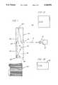
- FIG. 1is a schematic of the apparatus used to perform the method of the present invention
- FIG. 1Ais a cross-sectional view of the square laser beam after reflection by the integrator mirror
- FIG. 1Bis a cross-sectional view of the rectangular laser beam after reflection by the cylindrical mirror
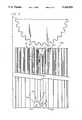
- FIG. 2is an end view of the apparatus shown in FIG. 1;
- FIG. 3is a view taken on lines 3--3 of FIG. 2;
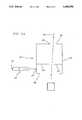
- FIG. 4Ais a diagrammatical view of the clipper box shown where the emitted square beam is uninterrupted;
- FIG. 4Bis a view similar to that of FIG. 4A, where the clipper box is pivoted to interrupt the light source;
- FIG. 4Cis a view, similar to that of FIG. 4B, where the clipper box is pivoted in the opposite direction to interrupt the light source from the opposite side;
- FIG. 4Dis an end view of the clipper rod of the clipper box shown in FIGS. 4A-4C;
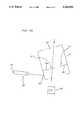
- FIG. 5is a cross-sectional view of a portion of a heat treated corrugating roll showing the degree of heat treating.
- a laser 10 having a Gaussian beam 12(or other non-uniform beam) is directed into an opening 14 of a lens box 16.
- a CO 2 laser 10is provided having a Gaussian beam output 12 with an oval-shaped cross-section, shown at 18, of 2-5/8 ⁇ 2-1/8 inches and set to provide an output power of 2-5 kilowatts.
- the Gaussian beam 12is directed into the opening 14 and towards a first flat mirror 20, which redirects the beam 12 against an integrator mirror 22.
- the integrator mirror 22is made up of a plurality of mirrors arranged in a grid, so arranged that they receive and focus the Gaussian beam 12 into a square beam of uniform density, or "top hat" beam 24.
- the top hat beam 24is directed through a clipper box 26 which interrupts the light path to shield or clip a portion of the top hat beam 24, described in greater detail hereafter.
- the shielded beam, shown at 28 in FIG. 1A,is thereafter directed towards a cylindrical mirror 30 which refocuses the shielded beam 28 into a rectangular beam 32 (FIG. 1B), which is in turn directed towards a spherical mirror 34.
- the spherical mirror 34is concave in nature and refocuses the rectangular beam 32 into a square beam 36 (FIG. 3), approximately 3/8 inch per side.
- the beam 36is directed through an opening 38 of the lens box 16, towards a corrugating roll 40 to be heat treated.
- the corrugating roll 40comprises a plurality of flutes 42, where the flutes 42 are sinuous in profile, consisting of flute tips 44 and root portions 46, with oblique portions or flanks 48, intermediate each tip and root.
- the beam 36is projected at, and laterally aligned with, a flute 42, as shown in FIG. 2.
- the beam 36is shielded, via the clipper box 26, to produce a beam pattern shown at 50, where the beam 50 is substantially U-shaped, having a transverse portion 50a and longitudinal beam portions 50b.
- the two longitudinal beam portions 50bare separated by a shielded or clipped section 50c formed by the light interruption of the clipper box 26.
- the beam 50is laterally centered with a flute tip 44, with the longitudinal beam portions 50b spanning the flanks 48 and roots 46 on opposite sides of one flute 42.
- the beam pattern 50spans at least one sinuous cycle of the flutes, from one root 46 to the next adjacent root 46.
- the clipper box 26is shown diagrammatically as including a generally box-shaped member 54, having a light inlet aperture 56, and an exit aperture 58.
- the reconfigured beam 24 from the integrator mirror 22is directed towards the clipper box 26, and if the clipper box is positioned as shown in FIG. 4A, the emitted beam 24 will pass through the box 26, uninterrupted, and through the aperture 38, as a square beam.
- the uninterrupted light beam shown in FIG. 4Ais only theoretical, as it is not the intention of the clipper box 26 to function in that mode.
- the clipper box 26is pivotal about point 60, and two clipper rods 62 and 64 extend inwardly from sidewalls of the clipper box 26.
- An air cylinder 66is pinned to the clipper box 26 at 68, and pinned to the lens box 16 at 70, and is actuable to pivot the clipper box between the extremes shown in FIGS. 4B and 4C.
- the heat treating processis begun, where the beam 36 is projected at one end of the corrugating roll.
- the clipper box 26is pivoted to the position shown in FIG. 4B via the air cylinder 66, and the rod 64 now interrupts the laser beam 24 to produce the beam configuration 50.
- the shielded section 50c of the beamis produced by the introduction of the rod 64 within the beam 24.
- the shielded section 50cis approximately the width of the flute tip 44, as best shown in FIG. 2.
- the heat treating processis begun by moving the beam 50 relative to the corrugating roll 40, such that the relative movement between the beam 50 and the corrugating roll 40, is in the direction of the arrow in FIG. 3, towards the center of the corrugating roll 40.
- the beam 50reaches position A
- the flute tips, roots and flanks corresponding to the longitudinal position at Abegin to be heated by the beam 50.
- the beam 50reaches the longitudinal position B
- the flute tip corresponding to longitudinal position Ais no longer heated, as the shielded or clipped portion 50c is passing thereover.
- the roots and flanks corresponding to position Bare, however, still heated, as the longitudinal sections 50b remain directly above them, and will be until the beam 50 reaches position C.
- the beam 50is moved from one end 40a, to the opposite end, by traversing the optical box 16 on precision tracks above, and relative to, the corrugating roll 40.
- the beam 50is moved at 65 inches/min., and the beam 50 is 3/8 inch square.
- the shielded portion 50chas a dimension X 2 of 1/4 inch, leaving the transverse section 50a with a dimension X 1 of 1/8 inch.
- each flute tipis heat treated for approximately 0.115 seconds, whereas the flanks and the roots are heat treated for approximately 0.345 second.
- the beamreaches the end of one flute 42, the next adjacent flute 42 is heat treated, and the corrugating roll is indexed to pick up the next flute.
- the clipper box 26is pivoted from the position shown in FIG. 4B to the position shown in FIG. 4C, via the air cylinder 66.
- the beam 51is now traversed in the opposite direction to heat treat the entire length of the next flute with the beam 51.
- the entire corrugating rollis heat treated by indexing the corrugating roll to position an un-heat treated flute with the beam.
- the rods 62 and 64have a cross-sectional shape as that shown in FIG. 4D having a semi-circular lower section 74, and tapered sections 76 facing the beam.
- the rodsare not overheated by the beam.
- the clippers 62 and 64are impinged with a flow of helium gas through ports 76 and 77, as shown in FIG. 4B.
- the corrugating roll 40is cleaned and coated with a light absorbing coating such as graphite or flat black paint and is positioned above the flute tip 44, such that a square spot 3/8 inch on each side is formed at the flute and the power density at the upper tip of the flute is approximately 35,000 W/in 2 .
- a light absorbing coatingsuch as graphite or flat black paint
- flute tips 44 of a corrugating roll having C-flutes heat treated by the above method with a power setting of 4.4 kwmay be hardened to a depth D of approximately 0.060-0.090 inches
- roots 46may be heat treated to a depth E of 0.024-0.030 inches
- the flanks 48may be heat treated to a depth F of 0.027-0.035 inches, and may be hardened to an average hardness of approximately 61-66 R c .
- the flute tips 44 of the corrugating roll flutes 42which are subjected to the greatest amount of abrasive forces during the corrugating process may be selectively provided with a hard surface to resist wear, but the roots and flanks may also be heat treated to a lesser degree, as they are subjected to minimal wear.
- the corrugating rollis water cooled to prevent overheating the roll. Approximately 1/2 GPM flow rate through the inner diameter of the roll has been found to be sufficient. The purpose of water cooling is to keep the roll body temperature low enough that a good self quench is achieved. The roll should be kept below 90° F. to achieve proper depth of hardening and high hardness.
- laser hardening of the steel corrugating rollscauses no decarburization at the surface of the roll.
- Decarburizationis caused by exposing the surface to hardening temperatures above 1550° F.
- the speed of heating and heat removalare so fast that it defies carbon removal. If the surface of the roll is decarburized, for example by induction, the surface of the steel has no carbon and therefore cannot achieve high hardness. If this occurs, the surface of the roll must be ground back to remove the decarburized layer and warpage due to the induction process.
- the grinding process itselfcan cause surface tempering of a few thousands of an inch.
Landscapes
- Engineering & Computer Science (AREA)
- Physics & Mathematics (AREA)
- Optics & Photonics (AREA)
- Chemical & Material Sciences (AREA)
- Mechanical Engineering (AREA)
- Plasma & Fusion (AREA)
- Thermal Sciences (AREA)
- Crystallography & Structural Chemistry (AREA)
- Materials Engineering (AREA)
- Metallurgy (AREA)
- Organic Chemistry (AREA)
- Heat Treatment Of Articles (AREA)
- Laser Beam Processing (AREA)
- Machines For Manufacturing Corrugated Board In Mechanical Paper-Making Processes (AREA)
Abstract
Description
Claims (16)
Priority Applications (6)
| Application Number | Priority Date | Filing Date | Title |
|---|---|---|---|
| US07/575,928US5160556A (en) | 1990-08-22 | 1990-08-31 | Method of hardening corrugating rolls |
| PCT/US1991/005769WO1992003580A1 (en) | 1990-08-22 | 1991-08-14 | Method of hardening corrugating rolls |
| ES91915520TES2102403T3 (en) | 1990-08-22 | 1991-08-14 | METHOD FOR HARDENING WAVE ROLLERS. |
| EP91915520AEP0547097B1 (en) | 1990-08-22 | 1991-08-14 | Method of hardening corrugating rolls |
| JP3514850AJPH06500151A (en) | 1990-08-22 | 1991-08-14 | How to harden corrugated rolls |
| DE69126030TDE69126030T2 (en) | 1990-08-22 | 1991-08-14 | METHOD FOR HARDENING RIFLE ROLLERS |
Applications Claiming Priority (2)
| Application Number | Priority Date | Filing Date | Title |
|---|---|---|---|
| US07/570,936US5180448A (en) | 1990-08-22 | 1990-08-22 | Method of laser hardening corrugating rolls |
| US07/575,928US5160556A (en) | 1990-08-22 | 1990-08-31 | Method of hardening corrugating rolls |
Related Parent Applications (1)
| Application Number | Title | Priority Date | Filing Date |
|---|---|---|---|
| US07/570,936Continuation-In-PartUS5180448A (en) | 1990-08-22 | 1990-08-22 | Method of laser hardening corrugating rolls |
Publications (1)
| Publication Number | Publication Date |
|---|---|
| US5160556Atrue US5160556A (en) | 1992-11-03 |
Family
ID=27075437
Family Applications (1)
| Application Number | Title | Priority Date | Filing Date |
|---|---|---|---|
| US07/575,928Expired - LifetimeUS5160556A (en) | 1990-08-22 | 1990-08-31 | Method of hardening corrugating rolls |
Country Status (6)
| Country | Link |
|---|---|
| US (1) | US5160556A (en) |
| EP (1) | EP0547097B1 (en) |
| JP (1) | JPH06500151A (en) |
| DE (1) | DE69126030T2 (en) |
| ES (1) | ES2102403T3 (en) |
| WO (1) | WO1992003580A1 (en) |
Cited By (14)
| Publication number | Priority date | Publication date | Assignee | Title |
|---|---|---|---|---|
| US5719373A (en)* | 1996-11-18 | 1998-02-17 | Ingersoll-Rand Company | Laser device for heating a surface formed by a small diameter bore in a workpiece |
| US5719376A (en)* | 1996-11-18 | 1998-02-17 | Ingersoll-Rand Company | Method for laser heating a surface formed by a circular bore extending through a workpiece |
| US6040551A (en)* | 1997-09-18 | 2000-03-21 | Rheinmetall W & M Gmbh | Apparatus for hardening the inside contour of a gun barrel with laser radiation |
| US6074507A (en)* | 1998-01-09 | 2000-06-13 | Corrugating Roll Corporation | Corrugating roll with improved flute profile |
| US6139462A (en)* | 1998-08-27 | 2000-10-31 | American Axle & Manufacturing, Inc. | Differential with laser hardened case |
| US6146476A (en)* | 1999-02-08 | 2000-11-14 | Alvord-Polk, Inc. | Laser-clad composite cutting tool and method |
| US6218642B1 (en) | 1999-07-12 | 2001-04-17 | J. F. Helmold & Bro., Inc. | Laser hardened steel cutting rule |
| US6566629B1 (en)* | 1997-02-25 | 2003-05-20 | Lsp Technologies, Inc. | Hidden surface laser shock processing |
| US20060118983A1 (en)* | 2004-12-03 | 2006-06-08 | Cochran Don W | Method and system for wavelength specific thermal irradiation and treatment |
| US20110062128A1 (en)* | 2009-09-14 | 2011-03-17 | Preco, Inc. | Multiple laser beam focusing head |
| US8303290B2 (en) | 2004-11-22 | 2012-11-06 | Sidel Participations | Method and installation for the production of containers |
| US8546277B2 (en) | 2007-03-02 | 2013-10-01 | Sidel Participations | Heating plastics via infrared radiation |
| US8662876B2 (en) | 2007-06-11 | 2014-03-04 | Sidel Participations | Installation for heating the bodies of preforms for blow-moulding containers |
| US10857722B2 (en) | 2004-12-03 | 2020-12-08 | Pressco Ip Llc | Method and system for laser-based, wavelength specific infrared irradiation treatment |
Families Citing this family (1)
| Publication number | Priority date | Publication date | Assignee | Title |
|---|---|---|---|---|
| GB9323946D0 (en)* | 1993-11-20 | 1994-01-05 | Langston The Corp | Manufacture of corrugated board |
Citations (5)
| Publication number | Priority date | Publication date | Assignee | Title |
|---|---|---|---|---|
| US3848104A (en)* | 1973-04-09 | 1974-11-12 | Avco Everett Res Lab Inc | Apparatus for heat treating a surface |
| US4154565A (en)* | 1978-05-05 | 1979-05-15 | Koppers Company, Inc. | Corrugator roll |
| US4250372A (en)* | 1978-07-07 | 1981-02-10 | Sumitomo Kinzoku Kogyo Kabushiki Gaisha | Process and apparatus for the heat treatment by high energy beams of surfaces of steel products |
| US4507538A (en)* | 1982-10-22 | 1985-03-26 | Mostek Corporation | Laser hardening with selective shielding |
| JPS63243218A (en)* | 1987-03-31 | 1988-10-11 | Komatsu Ltd | Laser hardening method |
Family Cites Families (4)
| Publication number | Priority date | Publication date | Assignee | Title |
|---|---|---|---|---|
| DE2018793B2 (en)* | 1970-04-20 | 1974-03-28 | Steigerwald Strahltechnik Gmbh, 8000 Muenchen | Process for the partial hardening of workpieces or tools |
| US4313771A (en)* | 1980-02-29 | 1982-02-02 | Xerox Corporation | Laser hardening of steel work pieces |
| DD259756A3 (en)* | 1986-05-20 | 1988-09-07 | Akad Wissenschaften Ddr | PARTIALLY SURFACED RIFFELWALZE AND SURFACE PROCESSING METHOD |
| DD270089A1 (en)* | 1988-03-21 | 1989-07-19 | Ardenne Forschungsinst | METHOD FOR PRODUCING HARDWARE ON WORKPIECES BY MEANS OF ELECTRON BEAM |
- 1990
- 1990-08-31USUS07/575,928patent/US5160556A/ennot_activeExpired - Lifetime
- 1991
- 1991-08-14DEDE69126030Tpatent/DE69126030T2/ennot_activeExpired - Fee Related
- 1991-08-14EPEP91915520Apatent/EP0547097B1/ennot_activeExpired - Lifetime
- 1991-08-14ESES91915520Tpatent/ES2102403T3/ennot_activeExpired - Lifetime
- 1991-08-14JPJP3514850Apatent/JPH06500151A/enactivePending
- 1991-08-14WOPCT/US1991/005769patent/WO1992003580A1/enactiveIP Right Grant
Patent Citations (5)
| Publication number | Priority date | Publication date | Assignee | Title |
|---|---|---|---|---|
| US3848104A (en)* | 1973-04-09 | 1974-11-12 | Avco Everett Res Lab Inc | Apparatus for heat treating a surface |
| US4154565A (en)* | 1978-05-05 | 1979-05-15 | Koppers Company, Inc. | Corrugator roll |
| US4250372A (en)* | 1978-07-07 | 1981-02-10 | Sumitomo Kinzoku Kogyo Kabushiki Gaisha | Process and apparatus for the heat treatment by high energy beams of surfaces of steel products |
| US4507538A (en)* | 1982-10-22 | 1985-03-26 | Mostek Corporation | Laser hardening with selective shielding |
| JPS63243218A (en)* | 1987-03-31 | 1988-10-11 | Komatsu Ltd | Laser hardening method |
Cited By (20)
| Publication number | Priority date | Publication date | Assignee | Title |
|---|---|---|---|---|
| US5719376A (en)* | 1996-11-18 | 1998-02-17 | Ingersoll-Rand Company | Method for laser heating a surface formed by a circular bore extending through a workpiece |
| US5719373A (en)* | 1996-11-18 | 1998-02-17 | Ingersoll-Rand Company | Laser device for heating a surface formed by a small diameter bore in a workpiece |
| US6566629B1 (en)* | 1997-02-25 | 2003-05-20 | Lsp Technologies, Inc. | Hidden surface laser shock processing |
| US6040551A (en)* | 1997-09-18 | 2000-03-21 | Rheinmetall W & M Gmbh | Apparatus for hardening the inside contour of a gun barrel with laser radiation |
| US6074507A (en)* | 1998-01-09 | 2000-06-13 | Corrugating Roll Corporation | Corrugating roll with improved flute profile |
| US6139462A (en)* | 1998-08-27 | 2000-10-31 | American Axle & Manufacturing, Inc. | Differential with laser hardened case |
| US6146476A (en)* | 1999-02-08 | 2000-11-14 | Alvord-Polk, Inc. | Laser-clad composite cutting tool and method |
| US6402438B1 (en) | 1999-02-08 | 2002-06-11 | Alvord-Polk, Inc. | Composite Cutting Tool |
| US6218642B1 (en) | 1999-07-12 | 2001-04-17 | J. F. Helmold & Bro., Inc. | Laser hardened steel cutting rule |
| US6335506B2 (en) | 1999-07-12 | 2002-01-01 | J. F. Helmold & Brothers, Inc. | Laser hardened steel cutting rule |
| US8303290B2 (en) | 2004-11-22 | 2012-11-06 | Sidel Participations | Method and installation for the production of containers |
| US8354051B2 (en) | 2004-11-22 | 2013-01-15 | Sidel Participations | Method and installation for the production of containers |
| US20060118983A1 (en)* | 2004-12-03 | 2006-06-08 | Cochran Don W | Method and system for wavelength specific thermal irradiation and treatment |
| US7425296B2 (en) | 2004-12-03 | 2008-09-16 | Pressco Technology Inc. | Method and system for wavelength specific thermal irradiation and treatment |
| US10857722B2 (en) | 2004-12-03 | 2020-12-08 | Pressco Ip Llc | Method and system for laser-based, wavelength specific infrared irradiation treatment |
| US11072094B2 (en) | 2004-12-03 | 2021-07-27 | Pressco Ip Llc | Method and system for wavelength specific thermal irradiation and treatment |
| US8546277B2 (en) | 2007-03-02 | 2013-10-01 | Sidel Participations | Heating plastics via infrared radiation |
| US8662876B2 (en) | 2007-06-11 | 2014-03-04 | Sidel Participations | Installation for heating the bodies of preforms for blow-moulding containers |
| US20110062128A1 (en)* | 2009-09-14 | 2011-03-17 | Preco, Inc. | Multiple laser beam focusing head |
| US10029331B2 (en) | 2009-09-14 | 2018-07-24 | Preco, Inc. | Multiple laser beam focusing head |
Also Published As
| Publication number | Publication date |
|---|---|
| DE69126030T2 (en) | 1997-11-06 |
| EP0547097B1 (en) | 1997-05-07 |
| DE69126030D1 (en) | 1997-06-12 |
| ES2102403T3 (en) | 1997-08-01 |
| WO1992003580A1 (en) | 1992-03-05 |
| EP0547097A1 (en) | 1993-06-23 |
| JPH06500151A (en) | 1994-01-06 |
Similar Documents
| Publication | Publication Date | Title |
|---|---|---|
| US5160556A (en) | Method of hardening corrugating rolls | |
| US4456811A (en) | Method of and apparatus for heat treating axisymmetric surfaces with an annular laser beam | |
| EP0147190B1 (en) | Method and apparatus for laser gear hardening | |
| US4304978A (en) | Heat treating using a laser | |
| US6016227A (en) | Apparatus and method for producing an improved laser beam | |
| US4507538A (en) | Laser hardening with selective shielding | |
| JPH0124202B2 (en) | ||
| GB2027752A (en) | Surface hardening by high energy beam | |
| JPS6163389A (en) | Treater for metallic work by power laser | |
| CN117583723B (en) | Beam shaping and adjustable beam energy density system and laser heat treatment process | |
| JPH09180185A (en) | Device for forming structure characteristic part on disk substrate with radiation beam | |
| JP6382154B2 (en) | Laser processing method and laser processing apparatus | |
| US5180448A (en) | Method of laser hardening corrugating rolls | |
| KR20040020605A (en) | A Laser Apparatus for Cutting through a Flat Workpiece and Cutting Method of Brittle Material, especially Glass Using Same | |
| GB2253282A (en) | Method and apparatus for controllably laser processing a surface | |
| JP2010052041A (en) | Processing method | |
| KR100300421B1 (en) | Method and apparatus of splitting glass | |
| JPH02263582A (en) | Method and device for treating material surfaces using laser energy | |
| US7521001B2 (en) | Surface treatment of concrete | |
| JP3200588B2 (en) | Laser distortion processing method and apparatus | |
| JPH11269536A (en) | Scorching of friction material | |
| RU2004603C1 (en) | Method for thermal hardening of metal items by laser radiation | |
| US20240102120A1 (en) | Method for laser hardening of a card wire | |
| JPH02141525A (en) | Surface hardening method using laser beam | |
| JPH03188212A (en) | Laser heat treatment method |
Legal Events
| Date | Code | Title | Description |
|---|---|---|---|
| AS | Assignment | Owner name:UNITED CONTAINER MACHINERY GROUP, INC. A CORPOR Free format text:ASSIGNMENT OF ASSIGNORS INTEREST.;ASSIGNORS:HYDE, GLENN F.;ULRICH, ROBERT R.;REEL/FRAME:006231/0848 Effective date:19920803 | |
| STCF | Information on status: patent grant | Free format text:PATENTED CASE | |
| CC | Certificate of correction | ||
| FPAY | Fee payment | Year of fee payment:4 | |
| AS | Assignment | Owner name:UNITED CONTAINER DHC, INC., DELAWARE Free format text:ASSIGNMENT OF ASSIGNORS INTEREST;ASSIGNOR:UNITED CONTAINER MACHINERY, INC.;REEL/FRAME:007936/0152 Effective date:19951027 | |
| AS | Assignment | Owner name:UNITED CONTAINER MACHINERY, INC., MARYLAND Free format text:CHANGE OF NAME;ASSIGNOR:UNITED CONTAINER MACHINERY GROUP, INC.;REEL/FRAME:008059/0990 Effective date:19950307 | |
| AS | Assignment | Owner name:BANK ONE, DAYTON, NATIONAL ASSOCIATION, OHIO Free format text:ASSIGNMENT OF ASSIGNORS INTEREST;ASSIGNOR:UNITED CONTAINER DHC, INC.;REEL/FRAME:008133/0981 Effective date:19960731 | |
| FPAY | Fee payment | Year of fee payment:8 | |
| AS | Assignment | Owner name:CIT GROUP/BUSINESS CREDIT, INC., THE, AS LENDER, N Free format text:NOTICE OF GRANT OF SECURITY INTEREST;ASSIGNOR:UNITED CONTAINER DHC, INC.;REEL/FRAME:011806/0987 Effective date:20010316 Owner name:BLACK CLAWSON COMPANY, INC., NEW YORK Free format text:NOTICE OF GRANT OF SECURITY INTEREST;ASSIGNOR:UNITED CONTAINER DHC, INC.;REEL/FRAME:011812/0001 Effective date:20010316 Owner name:LANDEGGER, GREGORY, NEW YORK Free format text:NOTICE OF GRANT OF SECURITY INTEREST;ASSIGNOR:UNITED CONTAINER DHC, INC.;REEL/FRAME:011812/0001 Effective date:20010316 Owner name:UNIVERSAL AMERICAN INC., NEW YORK Free format text:NOTICE OF GRANT OF SECURITY INTEREST;ASSIGNOR:UNITED CONTAINER DHC, INC.;REEL/FRAME:011812/0001 Effective date:20010316 | |
| AS | Assignment | Owner name:UNITED CONTAINER DHC, INC., MARYLAND Free format text:ASSIGNMENT OF ASSIGNORS INTEREST;ASSIGNOR:BANK ONE, N.A., FORMERLY KNOWN AS BANK ONE, DAYTON, NATIONAL ASSOCIATION;REEL/FRAME:013211/0336 Effective date:20020730 | |
| FPAY | Fee payment | Year of fee payment:12 |