US5160341A - Resorbable urethral stent and apparatus for its insertion - Google Patents
Resorbable urethral stent and apparatus for its insertionDownload PDFInfo
- Publication number
- US5160341A US5160341AUS07/610,543US61054390AUS5160341AUS 5160341 AUS5160341 AUS 5160341AUS 61054390 AUS61054390 AUS 61054390AUS 5160341 AUS5160341 AUS 5160341A
- Authority
- US
- United States
- Prior art keywords
- stent
- sheath
- diameter
- lumen
- bushing
- Prior art date
- Legal status (The legal status is an assumption and is not a legal conclusion. Google has not performed a legal analysis and makes no representation as to the accuracy of the status listed.)
- Expired - Lifetime
Links
Images

Classifications
- A—HUMAN NECESSITIES
- A61—MEDICAL OR VETERINARY SCIENCE; HYGIENE
- A61F—FILTERS IMPLANTABLE INTO BLOOD VESSELS; PROSTHESES; DEVICES PROVIDING PATENCY TO, OR PREVENTING COLLAPSING OF, TUBULAR STRUCTURES OF THE BODY, e.g. STENTS; ORTHOPAEDIC, NURSING OR CONTRACEPTIVE DEVICES; FOMENTATION; TREATMENT OR PROTECTION OF EYES OR EARS; BANDAGES, DRESSINGS OR ABSORBENT PADS; FIRST-AID KITS
- A61F2/00—Filters implantable into blood vessels; Prostheses, i.e. artificial substitutes or replacements for parts of the body; Appliances for connecting them with the body; Devices providing patency to, or preventing collapsing of, tubular structures of the body, e.g. stents
- A61F2/82—Devices providing patency to, or preventing collapsing of, tubular structures of the body, e.g. stents
- A61F2/86—Stents in a form characterised by the wire-like elements; Stents in the form characterised by a net-like or mesh-like structure
- A61F2/88—Stents in a form characterised by the wire-like elements; Stents in the form characterised by a net-like or mesh-like structure the wire-like elements formed as helical or spiral coils
- A—HUMAN NECESSITIES
- A61—MEDICAL OR VETERINARY SCIENCE; HYGIENE
- A61F—FILTERS IMPLANTABLE INTO BLOOD VESSELS; PROSTHESES; DEVICES PROVIDING PATENCY TO, OR PREVENTING COLLAPSING OF, TUBULAR STRUCTURES OF THE BODY, e.g. STENTS; ORTHOPAEDIC, NURSING OR CONTRACEPTIVE DEVICES; FOMENTATION; TREATMENT OR PROTECTION OF EYES OR EARS; BANDAGES, DRESSINGS OR ABSORBENT PADS; FIRST-AID KITS
- A61F2/00—Filters implantable into blood vessels; Prostheses, i.e. artificial substitutes or replacements for parts of the body; Appliances for connecting them with the body; Devices providing patency to, or preventing collapsing of, tubular structures of the body, e.g. stents
- A61F2/95—Instruments specially adapted for placement or removal of stents or stent-grafts
- A61F2/9517—Instruments specially adapted for placement or removal of stents or stent-grafts handle assemblies therefor
- A—HUMAN NECESSITIES
- A61—MEDICAL OR VETERINARY SCIENCE; HYGIENE
- A61F—FILTERS IMPLANTABLE INTO BLOOD VESSELS; PROSTHESES; DEVICES PROVIDING PATENCY TO, OR PREVENTING COLLAPSING OF, TUBULAR STRUCTURES OF THE BODY, e.g. STENTS; ORTHOPAEDIC, NURSING OR CONTRACEPTIVE DEVICES; FOMENTATION; TREATMENT OR PROTECTION OF EYES OR EARS; BANDAGES, DRESSINGS OR ABSORBENT PADS; FIRST-AID KITS
- A61F2/00—Filters implantable into blood vessels; Prostheses, i.e. artificial substitutes or replacements for parts of the body; Appliances for connecting them with the body; Devices providing patency to, or preventing collapsing of, tubular structures of the body, e.g. stents
- A61F2/95—Instruments specially adapted for placement or removal of stents or stent-grafts
- A61F2/962—Instruments specially adapted for placement or removal of stents or stent-grafts having an outer sleeve
- A61F2/966—Instruments specially adapted for placement or removal of stents or stent-grafts having an outer sleeve with relative longitudinal movement between outer sleeve and prosthesis, e.g. using a push rod
- A—HUMAN NECESSITIES
- A61—MEDICAL OR VETERINARY SCIENCE; HYGIENE
- A61F—FILTERS IMPLANTABLE INTO BLOOD VESSELS; PROSTHESES; DEVICES PROVIDING PATENCY TO, OR PREVENTING COLLAPSING OF, TUBULAR STRUCTURES OF THE BODY, e.g. STENTS; ORTHOPAEDIC, NURSING OR CONTRACEPTIVE DEVICES; FOMENTATION; TREATMENT OR PROTECTION OF EYES OR EARS; BANDAGES, DRESSINGS OR ABSORBENT PADS; FIRST-AID KITS
- A61F2/00—Filters implantable into blood vessels; Prostheses, i.e. artificial substitutes or replacements for parts of the body; Appliances for connecting them with the body; Devices providing patency to, or preventing collapsing of, tubular structures of the body, e.g. stents
- A61F2/02—Prostheses implantable into the body
- A61F2/04—Hollow or tubular parts of organs, e.g. bladders, tracheae, bronchi or bile ducts
- A61F2002/047—Urethrae
- A—HUMAN NECESSITIES
- A61—MEDICAL OR VETERINARY SCIENCE; HYGIENE
- A61F—FILTERS IMPLANTABLE INTO BLOOD VESSELS; PROSTHESES; DEVICES PROVIDING PATENCY TO, OR PREVENTING COLLAPSING OF, TUBULAR STRUCTURES OF THE BODY, e.g. STENTS; ORTHOPAEDIC, NURSING OR CONTRACEPTIVE DEVICES; FOMENTATION; TREATMENT OR PROTECTION OF EYES OR EARS; BANDAGES, DRESSINGS OR ABSORBENT PADS; FIRST-AID KITS
- A61F2210/00—Particular material properties of prostheses classified in groups A61F2/00 - A61F2/26 or A61F2/82 or A61F9/00 or A61F11/00 or subgroups thereof
- A61F2210/0004—Particular material properties of prostheses classified in groups A61F2/00 - A61F2/26 or A61F2/82 or A61F9/00 or A61F11/00 or subgroups thereof bioabsorbable
Definitions
- This inventionrelates to the field of urological methods and devices, and more particularly to such methods and devices as are used in the treatment of urethral stenoses. More specifically, the present invention relates to a urethral stent, and to a method and apparatus for inserting and locating the stent in a human male urethra to treat the stenosis therein.
- Stenosispartial occlusion of the human male urethra, resulting from disease or injury, is typically treated by surgery.
- Conventional surgical techniquessuch as dilation or commissurotomy, however, often offer only temporary or partial relief, since it is not uncommon for the stenosis to reoccur.
- Urethralare known in the art, as exemplified by U.S. Pat. No. 4,762,128 --Rosenbluth and U.S. Pat. No. 4,893,623--Rosenbluth, both commonly assigned to the assignee of the present application.
- the Rosenbluth patentsboth relate to methods and apparatus for the treatment of prostatic hypertrophy, wherein a urethral stenosis caused by a hypertrophied prostate gland is relieved by the implantation of a stent in the stenotic region of the urethra.
- the stents disclosed in the Rosenbluth patentsare in the form of radially expandable metallic tubes that are specifically adapted for implantation in the prostatic region of the urethra by means of a balloon catheter, and that, once in place, can withstand the radial pressures exerted by the hypertrophied prostate.
- Such stentsmay be less well-suited for implantation in the penile portion of the urethra (where many strictures occur), where less radial rigidity is needed, and where greater flexibility may be desired.
- An alternative stent configurationis that of a helically-coiled spring, such as that disclosed in U.S. Pat. No. 4,553,545 --Maass et al.
- the helically-coiled stent disclosed in the Maass et al. patentis made of a stainless steel or the like, and is specifically adapted for implantation as an intravascular prosthesis.
- the Maass et al. patentdiscloses a device for implanting the stent in a blood vessel.
- This implantation deviceis not suitable for implantation of the stent in a bodily lumen, such as the urethra, for a number of reasons, including the lack of means for visualizing the location of the stent within the enclosed lumen during implantation.
- U.S. Pat. No. 4,950,258 --Kawai et al.discloses a coil-shaped molded article, made from homopolymers or copolymers of lactides or glycolides, that can be used as a biodegradable vascular implant to open up an obstructed blood vessel.
- the coiled articlewould be deformed for insertion into the blood vessel, and then heated. The application of heat would cause the article to return to its original shape.
- temperatures in the range of 36 degrees Centigrade to 65 degrees Centigradewould apparently need to be applied to restore the article to its original shape in 10 seconds or less.
- the present inventionis an apparatus for relieving stenosis of the penile urethra, comprising a biodegradable, or resorbable, urethral stent, formed in the shape of a single or multiple helical coil that is resiliently deformable; and a device that includes means for (a) resiliently compressing the stent prior to insertion into the urethra; (b) inserting the compressed stent into the urethra in the vicinity of the stenosis, using direct visualization for positioning ; and (c) releasing the stent in the selected location in the urethra, allowing the stent to be restored to its original shape either through its natural resilience, or by forced expansion (or a combination thereof), thereby relieving the stenosis.
- the stentin the preferred embodiment of the invention, is formed from a biodegradable lactide homopolymer having an inherent viscosity of approximately 2.2.
- the stentwould maintain structural integrity for at least about one month, and, preferably, for about three to nine months.
- the resultant articleWhen formed into a coil shape, as by extrusion or molding, the resultant article is resiliently compressible, so that the coil has an uncompressed first diameter, and a compressed second diameter smaller than the first diameter. When the compressive force is released, the coil can resiliently spring back substantially to the first diameter.
- the stent lengthis ideally sized to equal or slightly exceed the length of the stricture.
- the stentis adapted for insertion into the urethra under direct endoscopic visualization, so that the stent fully supports the portion of the urethra that is narrowed by the stricture.
- the inserting deviceincludes a rotatable rod or core, coaxially surrounded by a stationary tubular bushing, the core having a head that is left exposed at one end of the bushing.
- the bushingin turn, is surrounded by a retractable tubular sheath.
- the stentin its normal shape (first diameter) has one end fixed to the core head and the other end fixed to the bushing.
- Core rotation meanspreferably a rack and pinion mechanism for operator convenience
- the sheath of the insertion deviceWith the stent in its compressed form, the sheath of the insertion device, in its extended position (covering the stent and the core head) is inserted into the urethra, with the help of visualization provided by a lens assembly and optical guide carried within (or along the side of) the sheath and extending axially along it.
- the sheathWhen the end of the sheath is located at the desired implantation site of the stent (i.e., proximate the stenosis), the sheath is withdrawn (by means of a lever, for example), and the core is counter-rotated with respect to the bushing, so as to unwind the stent back to its normal shape (first diameter).
- a tubular sleeve with an annular shearing edgeis disposed coaxially around the bushing, and is adapted for axial movement with respect to the bushing.
- the sleeveis moved forwardly so that the shearing edge severs the stent from its attachment points on the bushing and the core.
- the deviceis then removed from the urethra, leaving the stent in place at the stenosis site.
- the ends of the stentcould be held by a clamping mechanism on the core and the bushing, which would allow the stent to be released when desired.
- the insertion devicecomprises a hollow, tubular sheath and a hollow, tubular plunger that is insertable into the sheath.
- the outer end of the sheathis terminated by a hub assembly that includes a central bore, continuous and axially aligned with the interior of the sheath, and a threading guide at the outer opening of the bore.
- the plungerhas a first, or inner end to which one end of the stent is attached, the stent extending over a portion of the plunger proximate its inner end.
- the opposite, or outer end of the plungeris provided with a plunger hub assembly that mates with a lens assembly.
- the lens assemblyis optically coupled an optical guide that extends axially through the interior of the plunger.
- the sheathis first inserted into the urethra, using an obturator, which is subsequently removed.
- the inner end of the plunger, which carries the stentis placed adjacent to the bore opening in the sheath hub assembly, so as to engage the stent with the threading guide.
- the plungeris then rotated and pushed axially into the sheath hub assembly so as to thread the stent into the bore, thereby compressing the stent from its normal shape (first diameter) into its compressed shape (second diameter).
- the plungeris then pushed axially through the sheath, stopping short of the inner end of the sheath, so that the stent remains covered by the sheath.
- the inner end of the sheathis positioned to the desired implantation site.
- the plungeris pushed inwardly again to push the stent out of the sheath. No longer radially constrained by the sheath, the stent expands to its original shape (first diameter) at the implantation site. The sheath and plunger are then withdrawn from the urethra.
- both of the preferred embodiments of the insertion deviceexhibit significant advantages.
- both embodimentscan be employed, perhaps with relatively minor modifications, to install a helically-coiled implant in bodily passages other than the urethra.
- both embodimentsmay be used to install helically-coiled implants formed of any resilient, biocompatible material, not just those of a biodegradable polymer.
- both embodimentsoffer a heretofore unrealized facility in the installation of a urethral stent in the penile portion of the male urethra.
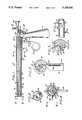
- FIG. 1is a side elevational view, partially in cross section, of a first preferred embodiment of a urethral stent insertion device, in accordance with the present invention
- FIG. 2is a front elevational view of the device of FIG. 1, taken along line 2--2 of FIG. 1;
- FIG. 3is a view taken along line 3--3 of FIG. 1;
- FIG. 4is a cross sectional view taken along line 4--4 of FIG. 1;
- FIG. 5is a cross sectional view taken along line 5--5 of FIG. 1;
- FIG. 6is a fragmentary side elevational view of the of FIG. 1, taken along line 6--6 of FIG. 4;
- FIG. 7is a partial cross sectional view, similar to that FIG. 1, showing the device with the sheath withdrawn and a urethral stent attached to the rotatable core and the stationary prior to insertion of the stent in a patient's urethra;
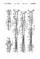
- FIGS. 8, 9, and 10are partial cross sectional Views, similar to that of FIG. 7, showing the steps in the process of inserting the stent into the urethra;
- FIG. 11is fragmentary perspective view of a second preferred embodiment of a stent insertion device, in accordance with the present invention, showing the outer portion of the sheath with the sheath hub assembly, and the inner end of the plunger with a urethral stent attached to it;
- FIG. 12is a longitudinal cross sectional View of the device of FIG. 11, showing the step of inserting the plunger and the stent into the sheath;
- FIGS. 13, 14, and 15are elevational views, partially in longitudinal cross section, showing the steps of inserting the stent into a patient's urethra using the device of FIG. 11.
- the device 10includes a hollow, tubular body 12 that is integral with a downwardly extending handle 14, the latter resembling a pistol grip in configuration.
- an elongate, hollow, tubular sheath 16Fitted into the body is one end of an elongate, hollow, tubular sheath 16, the other end of which (designated, for the purposes of this disclosure, as the distal end) terminates in a tapered tip 18 surrounding a distal opening.
- the sheath 16is axially movable between an extended position, shown in FIG. 1, and a withdrawn position, in which it is moved proximally (i.e., toward the handle 14).
- a rotatable rod or core 20Longitudinally disposed within the sheath is a rotatable rod or core 20, which is journaled within an elongate, tubular, stationary bushing 22.
- the core 20has a distal end that terminates in a knob or head 24 that is exposed from the distal end of the bushing 22, the bushing thereby extending proximally from the head 24.
- the head 24is provided with a first radial slot 26, and the bushing 22 is provided with a similar second radial slot 28 spaced from its distal end.
- the radial slots 26 and 28serve as first and second attachment points, respectively, for a stent, as explained below.
- an optical guide 30having a distal end 32 near the tip 18 of the sheath, and a proximal end that is adapted for attachment to a lens assembly 34.
- the optical assembly 30, 34provides direct visualization through the sheath 16.
- a tubular sleeve 36with an annular shearing edge 38 at its distal end, is disposed coaxially around the bushing 22, and is adapted to slide axially along the bushing.
- a downwardly-depending lever 40is provided, extending through a longitudinal slot 42 in the bottom of the housing 12. The purpose of the sleeve 36 will be explained below.
- the core 20is rotatable with respect to bushing 22.
- a variety of mechanismscan be used to effect this rotation, but in the preferred embodiment, a rack and pinion mechanism is used.
- the rack and pinion mechanismcomprises an arcuate rack 44 that operatively engages a pinion gear 46 attached to the proximal end of the core 20.
- the rack 44subtends an arc of slightly more than 90 degrees, passing through a cut-out 48 on one side of the handle 14.
- the lower end of the rack 44is attached to a core actuation lever 50.
- the core actuation lever 50has a bifurcated upper portion 52 that is pivotally attached to the housing 12, as best shown in FIG. 3.
- the lower end of the core actuation leveris advantageously provided with a finger hole 54 to facilitate moving the rack 44 up and down to rotate the pinion gear 46 (and thus the core 20) in either direction.
- the sheath 16is adapted for longitudinal or axial movement with respect to the housing 12.
- a pin 56extends laterally from the portion of the sheath enclosed within the housing, through a longitudinal slot 58 in the housing.
- the sheathis withdrawn or retracted from its extended position of FIG. 1 by pulling it proximally, so that the pin 56 moves proximally in the slot 58.
- the slot 58at its distal end, advantageously has a downward extension 60 that retains the pin 56 (upon a slight rotation of the sheath) when the sheath is in its fully extended position, thereby locking the sheath 16 in its extended position to facilitate insertion of the sheath into the urethra, as described below.
- the above-described embodiment of a stent insertion deviceis advantageously used to install a helically-coiled urethral stent 70 inside a patient's penile urethra 72.
- the stent 70is a coiled filament of a biocompatible and biodegradable (resorbable) polymer, preferably formed by extrusion. Suitable materials include polylactic acid (PLA) homopolymers, polyglycolic acid (PGA) homopolymers, and copolymers of PLA and PGA.
- a specific example of a suitable materialis a PLA homopolymer marketed by Henley Chemicals, Inc., of Montvale, N.J., under the trade name "RESOMER L 208", which has an inherent viscosity of approximately 2.2.
- the diameter of the filament that forms the stentmay be in the range of approximately 20 to 40 mils (approximately 0.5 to 1.0 mm).
- the material of the stentshould be selected for suitable resilient deformability. That is, a helically-coiled stent of such material should be capable of being deformably compressed, and then substantially restoring itself to its original size and shape by means of its own resiliency, without the need for the application of heat (other than, possibly, the ambient body temperature heat of the installation site).
- the stentshould be compressible from an original (first) diameter of approximately 36 French to a compressed (second) diameter of approximately 24 French, with the ability to restore itself substantially to the first diameter (36 French) when the compressing force is removed.
- a stent 70of the type described above, is disposed coaxially at the proximal end of the core/bushing assembly, with a first end attached to the core head 24 at the core head attachment slot 26, and a second end attached to the bushing at the bushing attachment slot 28.
- the insertion device 10can be delivered pre-loaded with the stent, or the physician can load the device immediately before the commencement of the insertion procedure.
- the stentshould be retained in its uncompressed, original configuration until the insertion procedure is begun to avoid the stent's taking a "set" due to plastic deformation.
- FIG. 8shows the device with the sheath 16 in its extended position.
- the core actuation lever 50has been pulled toward the handle 14 (proximally), thereby causing the rack 44 to move upwardly in engagement with the pinion gear 46, causing the latter to rotate in a first direction, thereby likewise rotating the core 20 with respect to the bushing 22.
- the rack and pinion mechanismBy virtue of the rack and pinion mechanism, a relatively small movement of the handle will result in multiple rotations of the core.
- the rotation of the core with respect to the bushingcauses the stent to become more tightly wound, thereby compressing the stent from its original (first) diameter to its compressed (second) diameter.
- the deviceis now ready for insertion into the urethra, the tapered tip 18 of the sheath 16 facilitating the insertion.
- Visualization of the urethra provided by the lens assembly 34 and the optical guide 30helps the physician properly locate the distal end of the sheath at the site of the urethral stenosis to be treated.
- the sheath 16is shown as having been inserted into the urethra 72, and retracted, as previously described, to expose the stent from the distal opening of the sheath.
- the core actuation lever 50is pushed distally (away from the handle 14), pulling the rack 44 downwardly in engagement with the pinion gear 46, thereby counter-rotating the pinion gear 46 and the core 20 in the opposite direction from that previously described.
- This counter-rotationcauses the stent to unwind, the resilience of the stent allowing it to assume, once again, substantially its original (first) diameter.
- the physiciancan continue to visualize the stent installation through the optical system 30,34, and, if necessary, rewind the stent, and adjust the position of the stent to relocate the stent with respect to the stenosis.
- the sleeve-actuating lever 40is pushed distally (away from the handle 14) through the housing slot 42, causing the sleeve 36 to move distally toward the core head 24.
- its shearing edge 38shears the connections between the stent and the bushing and between the stent and the core head, thereby discharging the stent from the insertion device.
- the insertion deviceis then withdrawn from the urethra, leaving the stent in place at the stenosis site to relieve the stenosis.
- FIGS. 11 through 15a urethral stent insertion device 80, in accordance with a second preferred embodiment of the invention is shown.
- This embodimentcomprises elongate, hollow, tubular sheath 82; an elongate, hollow, tubular plunger 84 that is insertable through the interior of the sheath 82; and an optical assembly that is operatively associated with the plunger 84 and the sheath 82.
- the sheath 82has an open distal end 86 and a proximal end to which is attached a hub 88.
- the hub 88has central bore 90 that is axially aligned and continuous with the interior of the sheath, terminating in a proximal opening 92 (FIG. 11).
- the internal diameter of the bore 90is approximately the same as that of the sheath 82.
- Extending radially into the bore 90 near the proximal opening 92is a threading guide 94, the purpose of which will be described below.
- the plunger 84has an outside diameter that is somewhat smaller than the inside diameter of the sheath 82, allowing the plunger to be inserted into the interior of the sheath with a predetermined circumferential clearance.
- the plungerhas a distal tip 96 having an axial slot 98 that is dimensioned to receive one end of a helically-coiled stent 70.
- the stent 70is thus carried coaxially on the distal end of the plunger 84, as shown in FIGS. 11 and 12.
- the stent 70may advantageously be the same type of stent as that which has previously been described herein.
- the proximal end of the plunger 84is provided with a hub 100 that provides a fitting for the attachment of the abovementioned optical assembly.
- the optical assemblyin turn, comprises a lens assembly 102 that mates with the plunger hub 100, and an optical guide 104 that is dimensioned to pass through the interior of the plunger 84.
- the sheath 82is introduced into the urethra 72, distal end 86 first, by an obturator (not shown), of a type well-known in the art, the obturator then being removed.
- the distal end of the plunger 84, with the stent 70 attached to it (as described above),is then inserted into the proximal opening 92 of the sheath hub 88, with the stent 70 being engaged by the threading guide 94, as shown in FIGS. 11 and 12.
- the plungeris then threaded into the central bore 90 of the sheath hub 88, and then into the interior of the sheath 82, as shown in FIG. 13.
- the optical guide 104is inserted into the interior of the plunger, until the lens assembly 102 is coupled to the plunger hub 100, as shown in FIG. 13. At this point, the stent is still retained totally within the sheath 82.
- the visualization provided by the optical guide 104 and the lens assembly 102allows the physician to locate distal end 86 of the sheath and move it to the desired location with respect to the implantation site.
- the plungeris pushed further through the sheath, until the stent is discharged from the distal end 86 of the sheath. As shown in FIG. 14, once the stent is clear of of the sheath, it resiliently restores itself to substantially its first diameter within the urethra.
- the plunger 84 and the optical assembly 102, 104are then removed from the sheath, and, finally, the sheath is removed from the urethra, leaving the stent in place.
- FIGS. 11 through 15offers the advantage of simplicity of construction and use, and is, therefore, especially adapted for disposability (at least with regard to the sheath and the plunger).
- the second embodimentwhile well-suited for insertion of a stent in the penile urethra, can easily be adapted for inserting a stent into other bodily lumens and passages.
- both of the above-described embodimentscan be used with helically-coiled stents formed of a variety of materials, not just the bioresorbable polymers describe herein.
- suitable stentscan be made of any of several well-known biocompatible (but not bioresorbable) polymers or metals that exhibit sufficient resiliency to restore themselves to their original shape and size, after having been compressed.
- the stentcan be coated or impregnated with an antimicrobial agent, such as silver oxide, to minimize the risk of infection.
- an antimicrobial agentsuch as silver oxide
- a resorbable stent impregnated with a drugcould be used as a drug delivery vehicle.
Landscapes
- Health & Medical Sciences (AREA)
- Engineering & Computer Science (AREA)
- Biomedical Technology (AREA)
- Cardiology (AREA)
- Oral & Maxillofacial Surgery (AREA)
- Transplantation (AREA)
- Heart & Thoracic Surgery (AREA)
- Vascular Medicine (AREA)
- Life Sciences & Earth Sciences (AREA)
- Animal Behavior & Ethology (AREA)
- General Health & Medical Sciences (AREA)
- Public Health (AREA)
- Veterinary Medicine (AREA)
- Media Introduction/Drainage Providing Device (AREA)
Abstract
Description
Claims (41)
Priority Applications (1)
| Application Number | Priority Date | Filing Date | Title |
|---|---|---|---|
| US07/610,543US5160341A (en) | 1990-11-08 | 1990-11-08 | Resorbable urethral stent and apparatus for its insertion |
Applications Claiming Priority (1)
| Application Number | Priority Date | Filing Date | Title |
|---|---|---|---|
| US07/610,543US5160341A (en) | 1990-11-08 | 1990-11-08 | Resorbable urethral stent and apparatus for its insertion |
Publications (1)
| Publication Number | Publication Date |
|---|---|
| US5160341Atrue US5160341A (en) | 1992-11-03 |
Family
ID=24445446
Family Applications (1)
| Application Number | Title | Priority Date | Filing Date |
|---|---|---|---|
| US07/610,543Expired - LifetimeUS5160341A (en) | 1990-11-08 | 1990-11-08 | Resorbable urethral stent and apparatus for its insertion |
Country Status (1)
| Country | Link |
|---|---|
| US (1) | US5160341A (en) |
Cited By (188)
| Publication number | Priority date | Publication date | Assignee | Title |
|---|---|---|---|---|
| US5201757A (en)* | 1992-04-03 | 1993-04-13 | Schneider (Usa) Inc. | Medial region deployment of radially self-expanding stents |
| US5282472A (en)* | 1993-05-11 | 1994-02-01 | Companion John A | System and process for the detection, evaluation and treatment of prostate and urinary problems |
| US5309894A (en)* | 1991-08-03 | 1994-05-10 | Richard Wolf Gmbh | Endoscope for introduction into a hollow organ of a living thing |
| EP0603423A1 (en)* | 1992-12-20 | 1994-06-29 | Schneider (Europe) Ag | Device for the implantation of an endoprothesis |
| WO1994022379A1 (en)* | 1993-03-30 | 1994-10-13 | Instent Inc. | Temporary stent system |
| EP0634152A1 (en)* | 1993-06-15 | 1995-01-18 | Esa Viherkoski | Biodegradable urethal stent |
| US5415664A (en)* | 1994-03-30 | 1995-05-16 | Corvita Corporation | Method and apparatus for introducing a stent or a stent-graft |
| US5571169A (en)* | 1993-06-07 | 1996-11-05 | Endovascular Instruments, Inc. | Anti-stenotic method and product for occluded and partially occluded arteries |
| US5571168A (en)* | 1995-04-05 | 1996-11-05 | Scimed Lifesystems Inc | Pull back stent delivery system |
| US5575816A (en)* | 1994-08-12 | 1996-11-19 | Meadox Medicals, Inc. | High strength and high density intraluminal wire stent |
| US5601591A (en)* | 1994-09-23 | 1997-02-11 | Vidamed, Inc. | Stent for use in prostatic urethra, apparatus and placement device for same and method |
| US5622188A (en)* | 1989-08-18 | 1997-04-22 | Endovascular Instruments, Inc. | Method of restoring reduced or absent blood flow capacity in an artery |
| US5628788A (en)* | 1995-11-07 | 1997-05-13 | Corvita Corporation | Self-expanding endoluminal stent-graft |
| US5643278A (en)* | 1995-04-06 | 1997-07-01 | Leocor, Inc. | Stent delivery system |
| EP0747021A3 (en)* | 1995-06-07 | 1997-10-01 | Cook Inc | Stent introducer |
| US5690643A (en)* | 1996-02-20 | 1997-11-25 | Leocor, Incorporated | Stent delivery system |
| US5700269A (en)* | 1995-06-06 | 1997-12-23 | Corvita Corporation | Endoluminal prosthesis deployment device for use with prostheses of variable length and having retraction ability |
| US5707387A (en)* | 1996-03-25 | 1998-01-13 | Wijay; Bandula | Flexible stent |
| US5741333A (en)* | 1995-04-12 | 1998-04-21 | Corvita Corporation | Self-expanding stent for a medical device to be introduced into a cavity of a body |
| US5741293A (en)* | 1995-11-28 | 1998-04-21 | Wijay; Bandula | Locking stent |
| US5746222A (en)* | 1995-12-14 | 1998-05-05 | Uromed Corporation | Urinary continence device for men and method of controlling urinary incontinence by using same |
| US5759186A (en)* | 1991-06-14 | 1998-06-02 | Ams Medinvent S.A. | Transluminal Implantation device |
| US5776142A (en)* | 1996-12-19 | 1998-07-07 | Medtronic, Inc. | Controllable stent delivery system and method |
| US5782838A (en)* | 1994-10-20 | 1998-07-21 | Medtronic Instent, Inc. | Cytoscope delivery system |
| US5788707A (en)* | 1995-06-07 | 1998-08-04 | Scimed Life Systems, Inc. | Pull back sleeve system with compression resistant inner shaft |
| US5792400A (en)* | 1988-11-10 | 1998-08-11 | Biocon Oy | Method of manufacturing biodegradable surgical implants and devices |
| US5824059A (en)* | 1997-08-05 | 1998-10-20 | Wijay; Bandula | Flexible stent |
| WO1998052496A1 (en)* | 1997-05-20 | 1998-11-26 | Biocompatibles Limited | Stent deployment device |
| US5849037A (en)* | 1995-04-12 | 1998-12-15 | Corvita Corporation | Self-expanding stent for a medical device to be introduced into a cavity of a body, and method for its preparation |
| US5888201A (en)* | 1996-02-08 | 1999-03-30 | Schneider (Usa) Inc | Titanium alloy self-expanding stent |
| US5927282A (en)* | 1991-01-10 | 1999-07-27 | Uromed Corporation | Controlling urinary incontinence |
| EP0943299A1 (en) | 1998-03-19 | 1999-09-22 | Indigo Medical, Incorporated | Intraluminal bellows medical construct and apparatus for using same |
| US5962007A (en)* | 1997-12-19 | 1999-10-05 | Indigo Medical, Inc. | Use of a multi-component coil medical construct |
| US5968052A (en)* | 1996-11-27 | 1999-10-19 | Scimed Life Systems Inc. | Pull back stent delivery system with pistol grip retraction handle |
| WO1999053865A1 (en)* | 1998-04-23 | 1999-10-28 | Boston Scientific Corporation | Stent deployment device and method for deploying a stent |
| US5980564A (en)* | 1997-08-01 | 1999-11-09 | Schneider (Usa) Inc. | Bioabsorbable implantable endoprosthesis with reservoir |
| US6019778A (en)* | 1998-03-13 | 2000-02-01 | Cordis Corporation | Delivery apparatus for a self-expanding stent |
| US6053940A (en)* | 1995-10-20 | 2000-04-25 | Wijay; Bandula | Vascular stent |
| US6090125A (en)* | 1995-04-20 | 2000-07-18 | Musc Foundation For Research Development | Anatomically shaped vasoocclusive device and method of making the same |
| US6090115A (en)* | 1995-06-07 | 2000-07-18 | Intratherapeutics, Inc. | Temporary stent system |
| US6102932A (en)* | 1998-12-15 | 2000-08-15 | Micrus Corporation | Intravascular device push wire delivery system |
| US6136015A (en)* | 1998-08-25 | 2000-10-24 | Micrus Corporation | Vasoocclusive coil |
| US6149664A (en)* | 1998-08-27 | 2000-11-21 | Micrus Corporation | Shape memory pusher introducer for vasoocclusive devices |
| US6159165A (en)* | 1997-12-05 | 2000-12-12 | Micrus Corporation | Three dimensional spherical micro-coils manufactured from radiopaque nickel-titanium microstrand |
| JP2000350785A (en)* | 1999-06-11 | 2000-12-19 | Arata Ishimaru | Stent (or stent graft) indwelling implement |
| US6162237A (en)* | 1999-04-19 | 2000-12-19 | Chan; Winston Kam Yew | Temporary intravascular stent for use in retrohepatic IVC or hepatic vein injury |
| US6165194A (en)* | 1998-07-24 | 2000-12-26 | Micrus Corporation | Intravascular flow modifier and reinforcement device |
| US6165140A (en)* | 1998-12-28 | 2000-12-26 | Micrus Corporation | Composite guidewire |
| US6168615B1 (en) | 1998-05-04 | 2001-01-02 | Micrus Corporation | Method and apparatus for occlusion and reinforcement of aneurysms |
| US6168570B1 (en) | 1997-12-05 | 2001-01-02 | Micrus Corporation | Micro-strand cable with enhanced radiopacity |
| US6171338B1 (en)* | 1988-11-10 | 2001-01-09 | Biocon, Oy | Biodegradable surgical implants and devices |
| US6171326B1 (en) | 1998-08-27 | 2001-01-09 | Micrus Corporation | Three dimensional, low friction vasoocclusive coil, and method of manufacture |
| US6174330B1 (en) | 1997-08-01 | 2001-01-16 | Schneider (Usa) Inc | Bioabsorbable marker having radiopaque constituents |
| US6184266B1 (en) | 1996-07-11 | 2001-02-06 | Scimed Life Systems, Inc. | Medical devices comprising cross-linked hydrogels having improved mechanical properties |
| US6203569B1 (en) | 1996-01-04 | 2001-03-20 | Bandula Wijay | Flexible stent |
| US6221066B1 (en) | 1999-03-09 | 2001-04-24 | Micrus Corporation | Shape memory segmented detachable coil |
| US6228111B1 (en) | 1995-09-27 | 2001-05-08 | Bionx Implants Oy | Biodegradable implant manufactured of polymer-based material and a method for manufacturing the same |
| US6235050B1 (en)* | 1994-05-12 | 2001-05-22 | Endovascular Technologies, Inc. | System and method for intraluminally deploying a bifurcated graft |
| US6241691B1 (en) | 1997-12-05 | 2001-06-05 | Micrus Corporation | Coated superelastic stent |
| US6245103B1 (en) | 1997-08-01 | 2001-06-12 | Schneider (Usa) Inc | Bioabsorbable self-expanding stent |
| US6248100B1 (en) | 1997-08-14 | 2001-06-19 | Scimed Life Systems, Inc. | Drainage catheter delivery system |
| WO2001043664A1 (en) | 1999-12-17 | 2001-06-21 | Bionx Implants, Oy | Urethral stent delivery system |
| US6251135B1 (en)* | 1997-08-01 | 2001-06-26 | Schneider (Usa) Inc | Radiopaque marker system and method of use |
| US6273895B1 (en) | 1995-06-06 | 2001-08-14 | Corvita Corporation | Method of measuring a body cavity |
| US6293960B1 (en) | 1998-05-22 | 2001-09-25 | Micrus Corporation | Catheter with shape memory polymer distal tip for deployment of therapeutic devices |
| US6296622B1 (en) | 1998-12-21 | 2001-10-02 | Micrus Corporation | Endoluminal device delivery system using axially recovering shape memory material |
| US20010029398A1 (en)* | 1999-06-03 | 2001-10-11 | Jadhav Balkrishna S. | Bioresorbable stent |
| US6338739B1 (en)* | 1999-12-22 | 2002-01-15 | Ethicon, Inc. | Biodegradable stent |
| US6340366B2 (en) | 1998-12-08 | 2002-01-22 | Bandula Wijay | Stent with nested or overlapping rings |
| KR100321647B1 (en)* | 1999-04-01 | 2002-01-23 | 윤율로 | A decomposable ureter stent in a living body, and a process for preparing the same. |
| US6352531B1 (en) | 1999-03-24 | 2002-03-05 | Micrus Corporation | Variable stiffness optical fiber shaft |
| US6371979B1 (en) | 1993-01-27 | 2002-04-16 | Intratherapeutics, Inc. | Stent delivery system |
| US6383204B1 (en) | 1998-12-15 | 2002-05-07 | Micrus Corporation | Variable stiffness coil for vasoocclusive devices |
| US6413269B1 (en) | 2000-07-06 | 2002-07-02 | Endocare, Inc. | Stent delivery system |
| US6425898B1 (en) | 1998-03-13 | 2002-07-30 | Cordis Corporation | Delivery apparatus for a self-expanding stent |
| US6428463B1 (en)* | 1995-12-18 | 2002-08-06 | Integrated Implant Systems, L.L.C. | Fiberoptic-guided interstitial seed manual applicator and seed cartridge |
| US6451025B1 (en) | 1996-04-01 | 2002-09-17 | General Surgical Innovations, Inc. | Prosthesis and method for deployment within a body lumen |
| US6478773B1 (en) | 1998-12-21 | 2002-11-12 | Micrus Corporation | Apparatus for deployment of micro-coil using a catheter |
| US6494908B1 (en) | 1999-12-22 | 2002-12-17 | Ethicon, Inc. | Removable stent for body lumens |
| US6500149B2 (en) | 1998-08-31 | 2002-12-31 | Deepak Gandhi | Apparatus for deployment of micro-coil using a catheter |
| US6500204B1 (en)* | 1998-09-08 | 2002-12-31 | Kabushikikaisha Igaki Iryo Sekkei | Stent for vessels |
| US6514261B1 (en)* | 1998-09-30 | 2003-02-04 | Impra, Inc. | Delivery mechanism for implantable stent |
| US6524345B1 (en) | 1996-10-25 | 2003-02-25 | Bionx Implants Oy | Surgical implant |
| US6533807B2 (en) | 1998-02-05 | 2003-03-18 | Medtronic, Inc. | Radially-expandable stent and delivery system |
| US20030069629A1 (en)* | 2001-06-01 | 2003-04-10 | Jadhav Balkrishna S. | Bioresorbable medical devices |
| US20030149472A1 (en)* | 1995-11-07 | 2003-08-07 | Leonard Pinchuk | Modular endluminal stent-grafts and methods for their use |
| US6629981B2 (en) | 2000-07-06 | 2003-10-07 | Endocare, Inc. | Stent delivery system |
| US6638291B1 (en) | 1995-04-20 | 2003-10-28 | Micrus Corporation | Three dimensional, low friction vasoocclusive coil, and method of manufacture |
| US6656218B1 (en) | 1998-07-24 | 2003-12-02 | Micrus Corporation | Intravascular flow modifier and reinforcement device |
| US6702846B2 (en) | 1996-04-09 | 2004-03-09 | Endocare, Inc. | Urological stent therapy system and method |
| US20040098095A1 (en)* | 1997-12-18 | 2004-05-20 | Burnside Diane K. | Stent-graft with bioabsorbable structural support |
| US6755854B2 (en)* | 2001-07-31 | 2004-06-29 | Advanced Cardiovascular Systems, Inc. | Control device and mechanism for deploying a self-expanding medical device |
| US6790223B2 (en) | 2001-09-21 | 2004-09-14 | Scimed Life Systems, Inc. | Delivering a uretheral stent |
| US20040199176A1 (en)* | 2001-06-15 | 2004-10-07 | Eric Berreklouw | Applicator for a prosthesis assembly comprising such an applicator and fixture system for loading such an applicator |
| US20040220660A1 (en)* | 2001-02-05 | 2004-11-04 | Shanley John F. | Bioresorbable stent with beneficial agent reservoirs |
| US6835185B2 (en) | 1998-12-21 | 2004-12-28 | Micrus Corporation | Intravascular device deployment mechanism incorporating mechanical detachment |
| US20050010279A1 (en)* | 2002-01-31 | 2005-01-13 | Lars Tenerz | Stent |
| US20050080476A1 (en)* | 2003-10-09 | 2005-04-14 | Gunderson Richard C. | Medical device delivery system |
| US6887215B2 (en) | 2001-06-01 | 2005-05-03 | Boston Scientific Scimed, Inc. | Compressible ureteral stent for comfort |
| US6887235B2 (en) | 1999-03-24 | 2005-05-03 | Micrus Corporation | Variable stiffness heating catheter |
| US20050096721A1 (en)* | 2003-10-29 | 2005-05-05 | Mangin Stephen P. | Apparatus with visual marker for guiding deployment of implantable prosthesis |
| US20050113748A1 (en)* | 1994-07-13 | 2005-05-26 | Marian Devonec | Therapeutic device for the selective cytoreduction treatment of an obstruction in a natural lumen or passage of the human or animal body |
| US20050137716A1 (en)* | 2003-12-17 | 2005-06-23 | Yosef Gross | Implant and delivery tool therefor |
| US20050149162A1 (en)* | 2003-12-29 | 2005-07-07 | Ethicon, Inc. | Urethral stent reducer |
| US20050177246A1 (en)* | 1999-12-22 | 2005-08-11 | Arindam Datta | Biodegradable stent |
| US20050222671A1 (en)* | 2004-03-31 | 2005-10-06 | Schaeffer Darin G | Partially biodegradable stent |
| US6981987B2 (en) | 1999-12-22 | 2006-01-03 | Ethicon, Inc. | Removable stent for body lumens |
| US6981964B2 (en) | 2001-05-22 | 2006-01-03 | Boston Scientific Scimed, Inc. | Draining bodily fluids with a stent |
| USD516723S1 (en) | 2004-07-06 | 2006-03-07 | Conor Medsystems, Inc. | Stent wall structure |
| US20060111772A1 (en)* | 2002-08-06 | 2006-05-25 | Icon Medical Corp. | Stent with micro-latching hinge joints |
| US7112226B2 (en) | 2002-10-22 | 2006-09-26 | Boston Scientific Scimed, Inc. | Male urethral stent device |
| US20060241682A1 (en)* | 2003-12-08 | 2006-10-26 | Kurz Daniel R | Intravascular device push wire delivery system |
| US7179289B2 (en) | 1998-03-30 | 2007-02-20 | Conor Medsystems, Inc. | Expandable medical device for delivery of beneficial agent |
| US20070142700A1 (en)* | 2005-12-19 | 2007-06-21 | Fogarty Terence M | Pump with one-touch release |
| US20070185372A1 (en)* | 2001-08-31 | 2007-08-09 | Ams Research Corporation | Surgical Articles for Placing an Implant about a Tubular Tissue Structure and Methods |
| US20080097523A1 (en)* | 1994-08-05 | 2008-04-24 | Lee Bolduc | Surgical helical fastener with applicator |
| US20090069836A1 (en)* | 2007-08-17 | 2009-03-12 | Micrus Endovascular Corporation | Twisted primary coil for vascular therapy |
| US20090319019A1 (en)* | 2008-06-23 | 2009-12-24 | Cook Incorporated | Expandable Tip Delivery System For Endoluminal Prosthesis |
| US7651529B2 (en) | 2003-05-09 | 2010-01-26 | Boston Scientific Scimed, Inc. | Stricture retractor |
| US20100069948A1 (en)* | 2008-09-12 | 2010-03-18 | Micrus Endovascular Corporation | Self-expandable aneurysm filling device, system and method of placement |
| US20100130815A1 (en)* | 2007-05-18 | 2010-05-27 | Prostaplant Ltd. | Intraurethral and extraurethral apparatus |
| US7740637B2 (en) | 2000-02-09 | 2010-06-22 | Micrus Endovascular Corporation | Apparatus and method for deployment of a therapeutic device using a catheter |
| US7771463B2 (en) | 2003-03-26 | 2010-08-10 | Ton Dai T | Twist-down implant delivery technologies |
| US7819912B2 (en) | 1998-03-30 | 2010-10-26 | Innovational Holdings Llc | Expandable medical device with beneficial agent delivery mechanism |
| US7842083B2 (en) | 2001-08-20 | 2010-11-30 | Innovational Holdings, Llc. | Expandable medical device with improved spatial distribution |
| US7850727B2 (en) | 2001-08-20 | 2010-12-14 | Innovational Holdings, Llc | Expandable medical device for delivery of beneficial agent |
| US7850728B2 (en) | 2000-10-16 | 2010-12-14 | Innovational Holdings Llc | Expandable medical device for delivery of beneficial agent |
| US7862602B2 (en)* | 2005-11-02 | 2011-01-04 | Biosensors International Group, Ltd | Indirect-release electrolytic implant delivery systems |
| US20110118540A1 (en)* | 2009-11-16 | 2011-05-19 | Coloplast A/S | Penile prosthetic with anti-autoinflation mechanism |
| US20110190577A1 (en)* | 2010-02-03 | 2011-08-04 | Coloplast A/S | Inflatable penile implant |
| US20110190576A1 (en)* | 2010-02-04 | 2011-08-04 | Coloplast A/S | Inflatable penile implant |
| US8016869B2 (en) | 2003-03-26 | 2011-09-13 | Biosensors International Group, Ltd. | Guidewire-less stent delivery methods |
| US8029555B2 (en) | 2004-03-31 | 2011-10-04 | Cook Medical Technologies Llc | Stent introducer system |
| US8088060B2 (en) | 2000-03-15 | 2012-01-03 | Orbusneich Medical, Inc. | Progenitor endothelial cell capturing with a drug eluting implantable medical device |
| US8147534B2 (en) | 2005-05-25 | 2012-04-03 | Tyco Healthcare Group Lp | System and method for delivering and deploying an occluding device within a vessel |
| US8257246B1 (en) | 2011-04-19 | 2012-09-04 | Coloplast A/S | Penile prosthetic system and pump having inlet valve with high velocity closure mechanism |
| US8267985B2 (en) | 2005-05-25 | 2012-09-18 | Tyco Healthcare Group Lp | System and method for delivering and deploying an occluding device within a vessel |
| US8273101B2 (en) | 2005-05-25 | 2012-09-25 | Tyco Healthcare Group Lp | System and method for delivering and deploying an occluding device within a vessel |
| US8382825B2 (en) | 2004-05-25 | 2013-02-26 | Covidien Lp | Flexible vascular occluding device |
| US8394119B2 (en) | 2006-02-22 | 2013-03-12 | Covidien Lp | Stents having radiopaque mesh |
| US8398701B2 (en) | 2004-05-25 | 2013-03-19 | Covidien Lp | Flexible vascular occluding device |
| US8460367B2 (en) | 2000-03-15 | 2013-06-11 | Orbusneich Medical, Inc. | Progenitor endothelial cell capturing with a drug eluting implantable medical device |
| US8535345B2 (en) | 2004-10-07 | 2013-09-17 | DePuy Synthes Products, LLC | Vasoocclusive coil with biplex windings to improve mechanical properties |
| US8617234B2 (en) | 2004-05-25 | 2013-12-31 | Covidien Lp | Flexible vascular occluding device |
| US8623067B2 (en) | 2004-05-25 | 2014-01-07 | Covidien Lp | Methods and apparatus for luminal stenting |
| US8652193B2 (en) | 2005-05-09 | 2014-02-18 | Angiomed Gmbh & Co. Medizintechnik Kg | Implant delivery device |
| US8657870B2 (en) | 2009-06-26 | 2014-02-25 | Biosensors International Group, Ltd. | Implant delivery apparatus and methods with electrolytic release |
| US8696732B2 (en) | 2010-08-04 | 2014-04-15 | Boston Scientific Scimed, Inc. | Stent delivery system |
| US8702784B2 (en) | 2010-10-14 | 2014-04-22 | Boston Scientific Scimed, Inc. | Outer tube for stent repositioning and deployment |
| US8753303B2 (en) | 2009-09-25 | 2014-06-17 | Boston Scientific Scimed, Inc. | Delivery system having stent locking structure |
| EP1637092A3 (en)* | 2001-04-30 | 2014-07-23 | Angiomed GmbH & Co. Medizintechnik KG | Self-expanding stent delivery device |
| US8790363B2 (en) | 1995-04-20 | 2014-07-29 | DePuy Synthes Products, LLC | Three dimensional, low friction vasoocclusive coil, and method of manufacture |
| US8808348B2 (en) | 2010-06-23 | 2014-08-19 | Boston Scientific Scimed, Inc. | Delivery system having stent retention structure |
| US20140236275A1 (en)* | 2001-01-18 | 2014-08-21 | Covidien Lp | Catheter system with spacer member |
| US20150005808A1 (en)* | 2013-06-26 | 2015-01-01 | W. L. Gore & Associates, Inc. | Medical device deployment system |
| US8961581B2 (en) | 2010-05-25 | 2015-02-24 | Boston Scientific Scimed, Inc. | Delivery system having stent retention structure |
| US8979824B2 (en) | 2010-06-21 | 2015-03-17 | Boston Scientific Scimed, Inc. | Stent delivery system having retention structure |
| US9114001B2 (en) | 2012-10-30 | 2015-08-25 | Covidien Lp | Systems for attaining a predetermined porosity of a vascular device |
| JP2015524712A (en)* | 2012-08-10 | 2015-08-27 | アルツラ メディカル インコーポレイテッド | Stent delivery system and related method |
| US9157174B2 (en) | 2013-02-05 | 2015-10-13 | Covidien Lp | Vascular device for aneurysm treatment and providing blood flow into a perforator vessel |
| US9155647B2 (en) | 2012-07-18 | 2015-10-13 | Covidien Lp | Methods and apparatus for luminal stenting |
| US9192500B1 (en) | 2015-01-29 | 2015-11-24 | Intact Vascular, Inc. | Delivery device and method of delivery |
| US9265637B2 (en) | 2010-11-19 | 2016-02-23 | Boston Scientific Scimed, Inc. | Rapid exchange stent delivery system |
| US9339631B2 (en) | 2009-09-25 | 2016-05-17 | Boston Scientific Scimed, Inc. | Locking mechanism for a medical device |
| US9375336B1 (en) | 2015-01-29 | 2016-06-28 | Intact Vascular, Inc. | Delivery device and method of delivery |
| US9408733B2 (en) | 2009-12-30 | 2016-08-09 | Michael Devon Amos | Rotatable connection between a tubular member and an elongate wire of a catheter |
| US9433520B2 (en) | 2015-01-29 | 2016-09-06 | Intact Vascular, Inc. | Delivery device and method of delivery |
| US9452070B2 (en) | 2012-10-31 | 2016-09-27 | Covidien Lp | Methods and systems for increasing a density of a region of a vascular device |
| US9456914B2 (en) | 2015-01-29 | 2016-10-04 | Intact Vascular, Inc. | Delivery device and method of delivery |
| US9498356B2 (en) | 2012-12-19 | 2016-11-22 | Cook Medical Technologies, LLC | Flexible stent and delivery system |
| US9522217B2 (en) | 2000-03-15 | 2016-12-20 | Orbusneich Medical, Inc. | Medical device with coating for capturing genetically-altered cells and methods for using same |
| US9554937B2 (en) | 2014-06-16 | 2017-01-31 | Coloplast A/S | Penile prosthetic pump having an inlet valve with a lockout flange |
| US9572652B2 (en) | 2009-12-01 | 2017-02-21 | Altura Medical, Inc. | Modular endograft devices and associated systems and methods |
| US9649217B2 (en) | 2014-07-08 | 2017-05-16 | Coloplast A/S | Implantable penile prosthetic lockout valve assembly |
| US9675482B2 (en) | 2008-05-13 | 2017-06-13 | Covidien Lp | Braid implant delivery systems |
| US9737426B2 (en) | 2013-03-15 | 2017-08-22 | Altura Medical, Inc. | Endograft device delivery systems and associated methods |
| US9763814B2 (en) | 2014-10-24 | 2017-09-19 | Cook Medical Technologies Llc | Elongate medical device |
| US9943427B2 (en) | 2012-11-06 | 2018-04-17 | Covidien Lp | Shaped occluding devices and methods of using the same |
| US9987136B2 (en) | 2016-09-09 | 2018-06-05 | Coloplast A/S | Penile prosthetic pump with an inflation assembly including a rotary valve |
| US10004618B2 (en) | 2004-05-25 | 2018-06-26 | Covidien Lp | Methods and apparatus for luminal stenting |
| US20200038213A1 (en)* | 2018-05-17 | 2020-02-06 | Zenflow, Inc. | Systems, devices, and methods for the accurate deployment and imaging of an implant in the prostatic urethra |
| EP3551140A4 (en)* | 2016-12-09 | 2020-07-08 | Zenflow, Inc. | Systems, devices, and methods for the accurate deployment of an implant in the prostatic urethra |
| US20200289268A1 (en)* | 2013-08-30 | 2020-09-17 | Bioventrix, Inc. | Heart anchor positioning devices, methods, and systems for treatment of congestive heart failure and other conditions |
| US10849771B2 (en) | 2011-06-27 | 2020-12-01 | Boston Scientific Scimed, Inc. | Stent delivery systems and methods for making and using stent delivery systems |
| US10993824B2 (en) | 2016-01-01 | 2021-05-04 | Intact Vascular, Inc. | Delivery device and method of delivery |
| WO2021101951A1 (en)* | 2019-11-19 | 2021-05-27 | Zenflow, Inc. | Systems, devices, and methods for the accurate deployment and imaging of an implant in the prostatic urethra |
| US11660218B2 (en) | 2017-07-26 | 2023-05-30 | Intact Vascular, Inc. | Delivery device and method of delivery |
| WO2025188864A1 (en)* | 2024-03-06 | 2025-09-12 | Aok Innovations Llc | Indwelling catheter-free stricture treatment |
Citations (20)
| Publication number | Priority date | Publication date | Assignee | Title |
|---|---|---|---|---|
| US3620218A (en)* | 1963-10-31 | 1971-11-16 | American Cyanamid Co | Cylindrical prosthetic devices of polyglycolic acid |
| US3887699A (en)* | 1969-03-24 | 1975-06-03 | Seymour Yolles | Biodegradable polymeric article for dispensing drugs |
| US4512338A (en)* | 1983-01-25 | 1985-04-23 | Balko Alexander B | Process for restoring patency to body vessels |
| US4531933A (en)* | 1982-12-07 | 1985-07-30 | C. R. Bard, Inc. | Helical ureteral stent |
| US4553545A (en)* | 1981-09-16 | 1985-11-19 | Medinvent S.A. | Device for application in blood vessels or other difficultly accessible locations and its use |
| US4650488A (en)* | 1984-05-16 | 1987-03-17 | Richards Medical Company | Biodegradable prosthetic device |
| US4660560A (en)* | 1985-05-30 | 1987-04-28 | The Beth Israel Hospital Association | Method for treating obstructive prostatism |
| US4665918A (en)* | 1986-01-06 | 1987-05-19 | Garza Gilbert A | Prosthesis system and method |
| US4670286A (en)* | 1983-09-20 | 1987-06-02 | Allied Corporation | Method of forming prosthetic devices |
| US4674506A (en)* | 1984-11-29 | 1987-06-23 | Kirk Alcond | Surgical anastomosis stent |
| US4732152A (en)* | 1984-12-05 | 1988-03-22 | Medinvent S.A. | Device for implantation and a method of implantation in a vessel using such device |
| US4762128A (en)* | 1986-12-09 | 1988-08-09 | Advanced Surgical Intervention, Inc. | Method and apparatus for treating hypertrophy of the prostate gland |
| US4768507A (en)* | 1986-02-24 | 1988-09-06 | Medinnovations, Inc. | Intravascular stent and percutaneous insertion catheter system for the dilation of an arterial stenosis and the prevention of arterial restenosis |
| US4820298A (en)* | 1987-11-20 | 1989-04-11 | Leveen Eric G | Internal vascular prosthesis |
| US4886062A (en)* | 1987-10-19 | 1989-12-12 | Medtronic, Inc. | Intravascular radially expandable stent and method of implant |
| US4886870A (en)* | 1984-05-21 | 1989-12-12 | Massachusetts Institute Of Technology | Bioerodible articles useful as implants and prostheses having predictable degradation rates |
| US4893623A (en)* | 1986-12-09 | 1990-01-16 | Advanced Surgical Intervention, Inc. | Method and apparatus for treating hypertrophy of the prostate gland |
| US4913141A (en)* | 1988-10-25 | 1990-04-03 | Cordis Corporation | Apparatus and method for placement of a stent within a subject vessel |
| US4950258A (en)* | 1988-01-28 | 1990-08-21 | Japan Medical Supply Co., Ltd. | Plastic molded articles with shape memory property |
| US4990155A (en)* | 1989-05-19 | 1991-02-05 | Wilkoff Howard M | Surgical stent method and apparatus |
- 1990
- 1990-11-08USUS07/610,543patent/US5160341A/ennot_activeExpired - Lifetime
Patent Citations (20)
| Publication number | Priority date | Publication date | Assignee | Title |
|---|---|---|---|---|
| US3620218A (en)* | 1963-10-31 | 1971-11-16 | American Cyanamid Co | Cylindrical prosthetic devices of polyglycolic acid |
| US3887699A (en)* | 1969-03-24 | 1975-06-03 | Seymour Yolles | Biodegradable polymeric article for dispensing drugs |
| US4553545A (en)* | 1981-09-16 | 1985-11-19 | Medinvent S.A. | Device for application in blood vessels or other difficultly accessible locations and its use |
| US4531933A (en)* | 1982-12-07 | 1985-07-30 | C. R. Bard, Inc. | Helical ureteral stent |
| US4512338A (en)* | 1983-01-25 | 1985-04-23 | Balko Alexander B | Process for restoring patency to body vessels |
| US4670286A (en)* | 1983-09-20 | 1987-06-02 | Allied Corporation | Method of forming prosthetic devices |
| US4650488A (en)* | 1984-05-16 | 1987-03-17 | Richards Medical Company | Biodegradable prosthetic device |
| US4886870A (en)* | 1984-05-21 | 1989-12-12 | Massachusetts Institute Of Technology | Bioerodible articles useful as implants and prostheses having predictable degradation rates |
| US4674506A (en)* | 1984-11-29 | 1987-06-23 | Kirk Alcond | Surgical anastomosis stent |
| US4732152A (en)* | 1984-12-05 | 1988-03-22 | Medinvent S.A. | Device for implantation and a method of implantation in a vessel using such device |
| US4660560A (en)* | 1985-05-30 | 1987-04-28 | The Beth Israel Hospital Association | Method for treating obstructive prostatism |
| US4665918A (en)* | 1986-01-06 | 1987-05-19 | Garza Gilbert A | Prosthesis system and method |
| US4768507A (en)* | 1986-02-24 | 1988-09-06 | Medinnovations, Inc. | Intravascular stent and percutaneous insertion catheter system for the dilation of an arterial stenosis and the prevention of arterial restenosis |
| US4762128A (en)* | 1986-12-09 | 1988-08-09 | Advanced Surgical Intervention, Inc. | Method and apparatus for treating hypertrophy of the prostate gland |
| US4893623A (en)* | 1986-12-09 | 1990-01-16 | Advanced Surgical Intervention, Inc. | Method and apparatus for treating hypertrophy of the prostate gland |
| US4886062A (en)* | 1987-10-19 | 1989-12-12 | Medtronic, Inc. | Intravascular radially expandable stent and method of implant |
| US4820298A (en)* | 1987-11-20 | 1989-04-11 | Leveen Eric G | Internal vascular prosthesis |
| US4950258A (en)* | 1988-01-28 | 1990-08-21 | Japan Medical Supply Co., Ltd. | Plastic molded articles with shape memory property |
| US4913141A (en)* | 1988-10-25 | 1990-04-03 | Cordis Corporation | Apparatus and method for placement of a stent within a subject vessel |
| US4990155A (en)* | 1989-05-19 | 1991-02-05 | Wilkoff Howard M | Surgical stent method and apparatus |
Cited By (385)
| Publication number | Priority date | Publication date | Assignee | Title |
|---|---|---|---|---|
| US6171338B1 (en)* | 1988-11-10 | 2001-01-09 | Biocon, Oy | Biodegradable surgical implants and devices |
| US5792400A (en)* | 1988-11-10 | 1998-08-11 | Biocon Oy | Method of manufacturing biodegradable surgical implants and devices |
| US5934284A (en)* | 1989-08-18 | 1999-08-10 | Endovascular Instruments, Inc | Method for increasing blood flow in vessels |
| US5662701A (en)* | 1989-08-18 | 1997-09-02 | Endovascular Instruments, Inc. | Anti-stenotic method and product for occluded and partially occluded arteries |
| US5622188A (en)* | 1989-08-18 | 1997-04-22 | Endovascular Instruments, Inc. | Method of restoring reduced or absent blood flow capacity in an artery |
| US5865844A (en)* | 1989-08-18 | 1999-02-02 | Endovascular Instruments, Inc. | Anti-stenotic method and product for occluded and partially occluded arteries |
| US5927282A (en)* | 1991-01-10 | 1999-07-27 | Uromed Corporation | Controlling urinary incontinence |
| US6131575A (en)* | 1991-01-10 | 2000-10-17 | The Procter & Gamble Company | Urinary incontinence device |
| US5759186A (en)* | 1991-06-14 | 1998-06-02 | Ams Medinvent S.A. | Transluminal Implantation device |
| US5954729A (en)* | 1991-06-14 | 1999-09-21 | Schneider (Usa) Inc. | Transluminal implantation device |
| US5309894A (en)* | 1991-08-03 | 1994-05-10 | Richard Wolf Gmbh | Endoscope for introduction into a hollow organ of a living thing |
| US5201757A (en)* | 1992-04-03 | 1993-04-13 | Schneider (Usa) Inc. | Medial region deployment of radially self-expanding stents |
| AU669581B2 (en)* | 1992-12-20 | 1996-06-13 | Schneider (Europe) Ag | Device for implanting an endoprosthesis |
| EP0603423A1 (en)* | 1992-12-20 | 1994-06-29 | Schneider (Europe) Ag | Device for the implantation of an endoprothesis |
| US6371979B1 (en) | 1993-01-27 | 2002-04-16 | Intratherapeutics, Inc. | Stent delivery system |
| US6371953B1 (en) | 1993-03-30 | 2002-04-16 | Intratherapeutics, Inc. | Temporary stent system |
| WO1994022379A1 (en)* | 1993-03-30 | 1994-10-13 | Instent Inc. | Temporary stent system |
| US5282472A (en)* | 1993-05-11 | 1994-02-01 | Companion John A | System and process for the detection, evaluation and treatment of prostate and urinary problems |
| US5842479A (en)* | 1993-06-07 | 1998-12-01 | Endovascular Instruments, Inc. | Method of restoring reduced or absent blood flow capacity |
| US5873905A (en)* | 1993-06-07 | 1999-02-23 | Endovascular Instruments, Inc. | Anti-stenotic method and product for occluded and partially occluded arteries |
| US5843165A (en)* | 1993-06-07 | 1998-12-01 | Endovascular Instruments, Inc. | Method for increasing blood flow in vessels |
| US5904146A (en)* | 1993-06-07 | 1999-05-18 | Endovascular Instruments, Inc. | Anti-stenotic method and product for occluded and partially occluded arteries |
| US6090135A (en)* | 1993-06-07 | 2000-07-18 | Endovascular Instruments, Inc. | Anti-stenotic method and product for occluded and partially occluded arteries |
| US5836316A (en)* | 1993-06-07 | 1998-11-17 | Endovascular Instruments, Inc. | Method of restoring reduced or absent blood flow capacity |
| US5571169A (en)* | 1993-06-07 | 1996-11-05 | Endovascular Instruments, Inc. | Anti-stenotic method and product for occluded and partially occluded arteries |
| US5824057A (en)* | 1993-06-07 | 1998-10-20 | Endo-Vascular Instruments, Inc. | Anti-stenotic method and product for occluded and partially occluded arteries |
| US5782847A (en)* | 1993-06-07 | 1998-07-21 | Endovascular Instruments, Inc. | Anti-stenotic method for occluded and partially occluded arteries |
| EP0634152A1 (en)* | 1993-06-15 | 1995-01-18 | Esa Viherkoski | Biodegradable urethal stent |
| WO1995026775A1 (en)* | 1994-03-30 | 1995-10-12 | Corvita Corporation | Method and apparatus for introducing a stent |
| US5415664A (en)* | 1994-03-30 | 1995-05-16 | Corvita Corporation | Method and apparatus for introducing a stent or a stent-graft |
| US7118594B2 (en) | 1994-05-12 | 2006-10-10 | Endovascular Technologies, Inc. | Bifurcated multicapsule intraluminal grafting system and method |
| US6235050B1 (en)* | 1994-05-12 | 2001-05-22 | Endovascular Technologies, Inc. | System and method for intraluminally deploying a bifurcated graft |
| US20050015141A1 (en)* | 1994-05-12 | 2005-01-20 | Quiachon Dinah B. | Bifurcated multicapsule intraluminal grafting system and method |
| US6663666B1 (en)* | 1994-05-12 | 2003-12-16 | Endovascular Technologies, Inc. | Delivery catheter for intraluminally deploying a graft |
| US20050113748A1 (en)* | 1994-07-13 | 2005-05-26 | Marian Devonec | Therapeutic device for the selective cytoreduction treatment of an obstruction in a natural lumen or passage of the human or animal body |
| US8211085B2 (en) | 1994-07-13 | 2012-07-03 | Marian Devonec | Therapeutic device for the selective cytoreduction treatment of an obstruction in a natural lumen or passage of the human or animal body |
| US6949083B2 (en)* | 1994-07-13 | 2005-09-27 | Marian Devonec | Therapeutic device for the selective cytoreduction treatment of an obstruction in a natural lumen or passage of the human or animal body |
| US20080097523A1 (en)* | 1994-08-05 | 2008-04-24 | Lee Bolduc | Surgical helical fastener with applicator |
| US20040193251A1 (en)* | 1994-08-12 | 2004-09-30 | Meadox Medicals, Inc. | Nested stent |
| US8092512B2 (en) | 1994-08-12 | 2012-01-10 | Boston Scientific Scimed, Inc. | Nested stent |
| US5906639A (en)* | 1994-08-12 | 1999-05-25 | Meadox Medicals, Inc. | High strength and high density intraluminal wire stent |
| US5575816A (en)* | 1994-08-12 | 1996-11-19 | Meadox Medicals, Inc. | High strength and high density intraluminal wire stent |
| US5601591A (en)* | 1994-09-23 | 1997-02-11 | Vidamed, Inc. | Stent for use in prostatic urethra, apparatus and placement device for same and method |
| US5782838A (en)* | 1994-10-20 | 1998-07-21 | Medtronic Instent, Inc. | Cytoscope delivery system |
| US5733267A (en)* | 1995-04-05 | 1998-03-31 | Scimed Life Systems, Inc. | Pull back stent delivery system |
| US5571168A (en)* | 1995-04-05 | 1996-11-05 | Scimed Lifesystems Inc | Pull back stent delivery system |
| US5643278A (en)* | 1995-04-06 | 1997-07-01 | Leocor, Inc. | Stent delivery system |
| US6237460B1 (en) | 1995-04-12 | 2001-05-29 | Corvita Corporation | Method for preparation of a self-expanding stent for a medical device to be introduced into a cavity of a body |
| US5849037A (en)* | 1995-04-12 | 1998-12-15 | Corvita Corporation | Self-expanding stent for a medical device to be introduced into a cavity of a body, and method for its preparation |
| US5741333A (en)* | 1995-04-12 | 1998-04-21 | Corvita Corporation | Self-expanding stent for a medical device to be introduced into a cavity of a body |
| US8790363B2 (en) | 1995-04-20 | 2014-07-29 | DePuy Synthes Products, LLC | Three dimensional, low friction vasoocclusive coil, and method of manufacture |
| US7316701B2 (en) | 1995-04-20 | 2008-01-08 | Micrus Endovascular Corporation | Three dimensional, low friction vasoocclusive coil, and method of manufacture |
| US6638291B1 (en) | 1995-04-20 | 2003-10-28 | Micrus Corporation | Three dimensional, low friction vasoocclusive coil, and method of manufacture |
| US6090125A (en)* | 1995-04-20 | 2000-07-18 | Musc Foundation For Research Development | Anatomically shaped vasoocclusive device and method of making the same |
| US5700269A (en)* | 1995-06-06 | 1997-12-23 | Corvita Corporation | Endoluminal prosthesis deployment device for use with prostheses of variable length and having retraction ability |
| US6273895B1 (en) | 1995-06-06 | 2001-08-14 | Corvita Corporation | Method of measuring a body cavity |
| US6090115A (en)* | 1995-06-07 | 2000-07-18 | Intratherapeutics, Inc. | Temporary stent system |
| US5788707A (en)* | 1995-06-07 | 1998-08-04 | Scimed Life Systems, Inc. | Pull back sleeve system with compression resistant inner shaft |
| US6342066B1 (en) | 1995-06-07 | 2002-01-29 | Scimed Life Systems, Inc. | Pull back sleeve system with compression resistant inner shaft |
| US6096045A (en)* | 1995-06-07 | 2000-08-01 | Scimed Life Systems, Inc. | Pull back sleeve system with compression resistant inner shaft |
| EP0747021A3 (en)* | 1995-06-07 | 1997-10-01 | Cook Inc | Stent introducer |
| US6228111B1 (en) | 1995-09-27 | 2001-05-08 | Bionx Implants Oy | Biodegradable implant manufactured of polymer-based material and a method for manufacturing the same |
| US6053940A (en)* | 1995-10-20 | 2000-04-25 | Wijay; Bandula | Vascular stent |
| US20030149472A1 (en)* | 1995-11-07 | 2003-08-07 | Leonard Pinchuk | Modular endluminal stent-grafts and methods for their use |
| US5628788A (en)* | 1995-11-07 | 1997-05-13 | Corvita Corporation | Self-expanding endoluminal stent-graft |
| US5741293A (en)* | 1995-11-28 | 1998-04-21 | Wijay; Bandula | Locking stent |
| US5746222A (en)* | 1995-12-14 | 1998-05-05 | Uromed Corporation | Urinary continence device for men and method of controlling urinary incontinence by using same |
| US6428463B1 (en)* | 1995-12-18 | 2002-08-06 | Integrated Implant Systems, L.L.C. | Fiberoptic-guided interstitial seed manual applicator and seed cartridge |
| US6203569B1 (en) | 1996-01-04 | 2001-03-20 | Bandula Wijay | Flexible stent |
| US5888201A (en)* | 1996-02-08 | 1999-03-30 | Schneider (Usa) Inc | Titanium alloy self-expanding stent |
| US5690643A (en)* | 1996-02-20 | 1997-11-25 | Leocor, Incorporated | Stent delivery system |
| US5707387A (en)* | 1996-03-25 | 1998-01-13 | Wijay; Bandula | Flexible stent |
| US6533805B1 (en)* | 1996-04-01 | 2003-03-18 | General Surgical Innovations, Inc. | Prosthesis and method for deployment within a body lumen |
| US7396362B2 (en) | 1996-04-01 | 2008-07-08 | General Surgical Innovations, Inc. | Prosthesis and method for deployment within a body lumen |
| US6451025B1 (en) | 1996-04-01 | 2002-09-17 | General Surgical Innovations, Inc. | Prosthesis and method for deployment within a body lumen |
| US6702846B2 (en) | 1996-04-09 | 2004-03-09 | Endocare, Inc. | Urological stent therapy system and method |
| US6184266B1 (en) | 1996-07-11 | 2001-02-06 | Scimed Life Systems, Inc. | Medical devices comprising cross-linked hydrogels having improved mechanical properties |
| US6387978B2 (en) | 1996-07-11 | 2002-05-14 | Boston Scientific Corporation | Medical devices comprising ionically and non-ionically crosslinked polymer hydrogels having improved mechanical properties |
| US6524345B1 (en) | 1996-10-25 | 2003-02-25 | Bionx Implants Oy | Surgical implant |
| US6391051B2 (en) | 1996-11-27 | 2002-05-21 | Scimed Life Systems, Inc. | Pull back stent delivery system with pistol grip retraction handle |
| US5968052A (en)* | 1996-11-27 | 1999-10-19 | Scimed Life Systems Inc. | Pull back stent delivery system with pistol grip retraction handle |
| US6238402B1 (en) | 1996-11-27 | 2001-05-29 | Boston Scientific Corporation | Pull back stent delivery system with pistol grip retraction handle |
| US5776142A (en)* | 1996-12-19 | 1998-07-07 | Medtronic, Inc. | Controllable stent delivery system and method |
| WO1998052496A1 (en)* | 1997-05-20 | 1998-11-26 | Biocompatibles Limited | Stent deployment device |
| US6174330B1 (en) | 1997-08-01 | 2001-01-16 | Schneider (Usa) Inc | Bioabsorbable marker having radiopaque constituents |
| US6251135B1 (en)* | 1997-08-01 | 2001-06-26 | Schneider (Usa) Inc | Radiopaque marker system and method of use |
| US5980564A (en)* | 1997-08-01 | 1999-11-09 | Schneider (Usa) Inc. | Bioabsorbable implantable endoprosthesis with reservoir |
| US6245103B1 (en) | 1997-08-01 | 2001-06-12 | Schneider (Usa) Inc | Bioabsorbable self-expanding stent |
| US20090259125A1 (en)* | 1997-08-01 | 2009-10-15 | Boston Scientific Scimed, Inc. | Bioabsorbable Marker Having Radiopaque Constituents And Method of Using the Same |
| US7758631B2 (en) | 1997-08-01 | 2010-07-20 | Boston Scientific Scimed, Inc. | Bioabsorbable endoprosthesis having elongate axial reservoir for by-product collection |
| US20040111149A1 (en)* | 1997-08-01 | 2004-06-10 | Stinson Jonathan S. | Bioabsorbable marker having radiopaque constituents |
| US7553325B2 (en) | 1997-08-01 | 2009-06-30 | Boston Scientific Scimed, Inc. | Bioabsorbable marker having radiopaque constituents |
| US6340367B1 (en) | 1997-08-01 | 2002-01-22 | Boston Scientific Scimed, Inc. | Radiopaque markers and methods of using the same |
| US20040106984A1 (en)* | 1997-08-01 | 2004-06-03 | Stinson Jonathan S. | Bioabsorbable endoprosthesis having elongate axial reservoir for by-product collection |
| US5824059A (en)* | 1997-08-05 | 1998-10-20 | Wijay; Bandula | Flexible stent |
| US6248100B1 (en) | 1997-08-14 | 2001-06-19 | Scimed Life Systems, Inc. | Drainage catheter delivery system |
| US6562024B2 (en) | 1997-08-14 | 2003-05-13 | Scimed Life Systems, Inc. | Drainage catheter delivery system |
| US7326225B2 (en) | 1997-12-05 | 2008-02-05 | Micrus Endovascular Corporation | Vasoocclusive device for treatment of aneurysms |
| US6168570B1 (en) | 1997-12-05 | 2001-01-02 | Micrus Corporation | Micro-strand cable with enhanced radiopacity |
| US6497671B2 (en) | 1997-12-05 | 2002-12-24 | Micrus Corporation | Coated superelastic stent |
| US6241691B1 (en) | 1997-12-05 | 2001-06-05 | Micrus Corporation | Coated superelastic stent |
| US6475169B2 (en) | 1997-12-05 | 2002-11-05 | Micrus Corporation | Micro-strand cable with enhanced radiopacity |
| US6616617B1 (en) | 1997-12-05 | 2003-09-09 | Micrus Corporation | Vasoocclusive device for treatment of aneurysms |
| US6159165A (en)* | 1997-12-05 | 2000-12-12 | Micrus Corporation | Three dimensional spherical micro-coils manufactured from radiopaque nickel-titanium microstrand |
| US7070608B2 (en) | 1997-12-05 | 2006-07-04 | Micrus Corporation | Vasoocclusive coil |
| US20040098095A1 (en)* | 1997-12-18 | 2004-05-20 | Burnside Diane K. | Stent-graft with bioabsorbable structural support |
| US20060266474A1 (en)* | 1997-12-18 | 2006-11-30 | Schneider (Usa) Inc. | Stent-graft with bioabsorbable structural support |
| US9833343B2 (en) | 1997-12-18 | 2017-12-05 | Boston Scientific Scimed, Inc. | Stent-graft with bioabsorbable structural support |
| US7699887B2 (en) | 1997-12-18 | 2010-04-20 | Boston Scientific Scimed, Inc. | Stent-graft with bioabsorbable structural support |
| US7108716B2 (en) | 1997-12-18 | 2006-09-19 | Schneider (Usa) Inc. | Stent-graft with bioabsorbable structural support |
| US5962007A (en)* | 1997-12-19 | 1999-10-05 | Indigo Medical, Inc. | Use of a multi-component coil medical construct |
| US6533807B2 (en) | 1998-02-05 | 2003-03-18 | Medtronic, Inc. | Radially-expandable stent and delivery system |
| US20030144731A1 (en)* | 1998-02-05 | 2003-07-31 | Medtronic, Inc. | Radially-expandable stent and delivery system |
| US6613079B1 (en) | 1998-02-05 | 2003-09-02 | Medtronic, Inc. | Radially-expandable stent with controllable force profile |
| US6019778A (en)* | 1998-03-13 | 2000-02-01 | Cordis Corporation | Delivery apparatus for a self-expanding stent |
| US6425898B1 (en) | 1998-03-13 | 2002-07-30 | Cordis Corporation | Delivery apparatus for a self-expanding stent |
| US6001117A (en)* | 1998-03-19 | 1999-12-14 | Indigo Medical, Inc. | Bellows medical construct and apparatus and method for using same |
| EP0943299A1 (en) | 1998-03-19 | 1999-09-22 | Indigo Medical, Incorporated | Intraluminal bellows medical construct and apparatus for using same |
| US8439968B2 (en) | 1998-03-30 | 2013-05-14 | Innovational Holdings, Llc | Expandable medical device for delivery of beneficial agent |
| US8052735B2 (en) | 1998-03-30 | 2011-11-08 | Innovational Holdings, Llc | Expandable medical device with ductile hinges |
| US8052734B2 (en) | 1998-03-30 | 2011-11-08 | Innovational Holdings, Llc | Expandable medical device with beneficial agent delivery mechanism |
| US7896912B2 (en) | 1998-03-30 | 2011-03-01 | Innovational Holdings, Llc | Expandable medical device with S-shaped bridging elements |
| US7819912B2 (en) | 1998-03-30 | 2010-10-26 | Innovational Holdings Llc | Expandable medical device with beneficial agent delivery mechanism |
| US7179289B2 (en) | 1998-03-30 | 2007-02-20 | Conor Medsystems, Inc. | Expandable medical device for delivery of beneficial agent |
| US6146389A (en)* | 1998-04-23 | 2000-11-14 | Boston Scientific Corporation | Stent deployment device and method for deploying a stent |
| US6576005B1 (en) | 1998-04-23 | 2003-06-10 | Boston Scientific Corporation | Stent deployment device and method for deploying a stent |
| WO1999053865A1 (en)* | 1998-04-23 | 1999-10-28 | Boston Scientific Corporation | Stent deployment device and method for deploying a stent |
| USRE42758E1 (en) | 1998-05-04 | 2011-09-27 | Micrus Corporation | Expandable curvilinear strut arrangement for deployment with a catheter to repair an aneurysm |
| US6168615B1 (en) | 1998-05-04 | 2001-01-02 | Micrus Corporation | Method and apparatus for occlusion and reinforcement of aneurysms |
| US6293960B1 (en) | 1998-05-22 | 2001-09-25 | Micrus Corporation | Catheter with shape memory polymer distal tip for deployment of therapeutic devices |
| US6416541B2 (en) | 1998-07-24 | 2002-07-09 | Micrus Corporation | Intravascular flow modifier and reinforcement device |
| US6656218B1 (en) | 1998-07-24 | 2003-12-02 | Micrus Corporation | Intravascular flow modifier and reinforcement device |
| US6165194A (en)* | 1998-07-24 | 2000-12-26 | Micrus Corporation | Intravascular flow modifier and reinforcement device |
| US6855155B2 (en) | 1998-07-24 | 2005-02-15 | Micrus Corporation | Intravascular flow modifier and reinforcement device |
| US6913618B2 (en) | 1998-07-24 | 2005-07-05 | Micrus Corporation | Intravascular flow modifier and reinforcement device |
| US6136015A (en)* | 1998-08-25 | 2000-10-24 | Micrus Corporation | Vasoocclusive coil |
| US6306153B1 (en) | 1998-08-25 | 2001-10-23 | Micrus Corporation | Vasoocclusive coil |
| US6149664A (en)* | 1998-08-27 | 2000-11-21 | Micrus Corporation | Shape memory pusher introducer for vasoocclusive devices |
| US6171326B1 (en) | 1998-08-27 | 2001-01-09 | Micrus Corporation | Three dimensional, low friction vasoocclusive coil, and method of manufacture |
| US6500149B2 (en) | 1998-08-31 | 2002-12-31 | Deepak Gandhi | Apparatus for deployment of micro-coil using a catheter |
| US7066952B2 (en)* | 1998-09-08 | 2006-06-27 | Kabushikikaisha Igaki Iryo Sekkei | Method for manufacturing yarn for vessel stent |
| US6500204B1 (en)* | 1998-09-08 | 2002-12-31 | Kabushikikaisha Igaki Iryo Sekkei | Stent for vessels |
| US20030055488A1 (en)* | 1998-09-08 | 2003-03-20 | Keiji Igaki | Method for manufacturing yarn for vessel stent |
| US20040215330A1 (en)* | 1998-09-08 | 2004-10-28 | Keiji Igaki | Stent for vessel |
| US7335226B2 (en) | 1998-09-08 | 2008-02-26 | Kabushikikaisha Igaki Iryo Sekkei | Yarn for vessel stent |
| US7331988B2 (en) | 1998-09-08 | 2008-02-19 | Kabushikikaisha Igaki Iryo Sekkei | Stent for vessel |
| US8852266B2 (en) | 1998-09-30 | 2014-10-07 | Bard Peripheral Vascular, Inc. | Delivery mechanism for implantable stent |
| US6514261B1 (en)* | 1998-09-30 | 2003-02-04 | Impra, Inc. | Delivery mechanism for implantable stent |
| US7122050B2 (en) | 1998-09-30 | 2006-10-17 | Bard Peripheral Vascular, Inc. | Delivery mechanism for implantable stent |
| US6340366B2 (en) | 1998-12-08 | 2002-01-22 | Bandula Wijay | Stent with nested or overlapping rings |
| US7147618B2 (en) | 1998-12-15 | 2006-12-12 | Micrus Endovascular Corporation | Intravascular device push wire delivery system |
| US6679903B2 (en) | 1998-12-15 | 2004-01-20 | Micrus Corporation | Intravascular device push wire delivery system |
| US6872218B2 (en) | 1998-12-15 | 2005-03-29 | Micrus Corporation | Variable stiffness coil for vasoocclusive devices |
| US6656201B2 (en) | 1998-12-15 | 2003-12-02 | Micrus Corporation | Variable stiffness coil for vasoocclusive devices |
| US20040122502A1 (en)* | 1998-12-15 | 2004-06-24 | Kurz Daniel R. | Intravascular device push wire delivery system |
| US6102932A (en)* | 1998-12-15 | 2000-08-15 | Micrus Corporation | Intravascular device push wire delivery system |
| US6319267B1 (en) | 1998-12-15 | 2001-11-20 | Micrus Corporation | Intravascular device push wire delivery system |
| US6383204B1 (en) | 1998-12-15 | 2002-05-07 | Micrus Corporation | Variable stiffness coil for vasoocclusive devices |
| US6478773B1 (en) | 1998-12-21 | 2002-11-12 | Micrus Corporation | Apparatus for deployment of micro-coil using a catheter |
| US9622754B2 (en) | 1998-12-21 | 2017-04-18 | DePuy Synthes Products, Inc. | Intravascular device deployment mechanism incorporating mechanical detachment |
| US6835185B2 (en) | 1998-12-21 | 2004-12-28 | Micrus Corporation | Intravascular device deployment mechanism incorporating mechanical detachment |
| US6966892B2 (en) | 1998-12-21 | 2005-11-22 | Micrus Corporation | Apparatus for deployment of micro-coil using a catheter |
| US6296622B1 (en) | 1998-12-21 | 2001-10-02 | Micrus Corporation | Endoluminal device delivery system using axially recovering shape memory material |
| US7255707B2 (en) | 1998-12-21 | 2007-08-14 | Micrus Endovascular Corporation | Intravascular device deployment mechanism incorporating mechanical detachment |
| US6432066B1 (en) | 1998-12-28 | 2002-08-13 | Micrus Corporation | Composite guidewire |
| US6595932B2 (en) | 1998-12-28 | 2003-07-22 | Micrus Corporation | Composite guidewire |
| US6165140A (en)* | 1998-12-28 | 2000-12-26 | Micrus Corporation | Composite guidewire |
| US7014616B2 (en) | 1998-12-28 | 2006-03-21 | Micrus Corporation | Composite guidewire |
| US6551305B2 (en)* | 1999-03-09 | 2003-04-22 | Micrus Corporation | Shape memory segmented detachable coil |
| US6221066B1 (en) | 1999-03-09 | 2001-04-24 | Micrus Corporation | Shape memory segmented detachable coil |
| US6352531B1 (en) | 1999-03-24 | 2002-03-05 | Micrus Corporation | Variable stiffness optical fiber shaft |
| US7645275B2 (en) | 1999-03-24 | 2010-01-12 | Micrus Corporation | Variable stiffness heating catheter |
| US8282677B2 (en) | 1999-03-24 | 2012-10-09 | Micrus Corporation | Variable stiffness heating catheter |
| US7066931B2 (en) | 1999-03-24 | 2006-06-27 | Micrus Corporation | Variable stiffness heating catheter |
| US6887235B2 (en) | 1999-03-24 | 2005-05-03 | Micrus Corporation | Variable stiffness heating catheter |
| KR100321647B1 (en)* | 1999-04-01 | 2002-01-23 | 윤율로 | A decomposable ureter stent in a living body, and a process for preparing the same. |
| US6162237A (en)* | 1999-04-19 | 2000-12-19 | Chan; Winston Kam Yew | Temporary intravascular stent for use in retrohepatic IVC or hepatic vein injury |
| US20010029398A1 (en)* | 1999-06-03 | 2001-10-11 | Jadhav Balkrishna S. | Bioresorbable stent |
| US6991647B2 (en)* | 1999-06-03 | 2006-01-31 | Ams Research Corporation | Bioresorbable stent |
| US6368346B1 (en) | 1999-06-03 | 2002-04-09 | American Medical Systems, Inc. | Bioresorbable stent |
| JP2000350785A (en)* | 1999-06-11 | 2000-12-19 | Arata Ishimaru | Stent (or stent graft) indwelling implement |
| WO2001043664A1 (en) | 1999-12-17 | 2001-06-21 | Bionx Implants, Oy | Urethral stent delivery system |
| US6685734B1 (en) | 1999-12-17 | 2004-02-03 | Linvatec Biomaterials Oy | Urethral stent delivery system |
| US6981987B2 (en) | 1999-12-22 | 2006-01-03 | Ethicon, Inc. | Removable stent for body lumens |
| US20050177246A1 (en)* | 1999-12-22 | 2005-08-11 | Arindam Datta | Biodegradable stent |
| US6423092B2 (en)* | 1999-12-22 | 2002-07-23 | Ethicon, Inc. | Biodegradable stent |
| US7163562B2 (en) | 1999-12-22 | 2007-01-16 | Ethicon, Inc. | Biodegradable stent |
| US7166134B2 (en) | 1999-12-22 | 2007-01-23 | Ethicon, Inc. | Biodegradable stent |
| US7169187B2 (en) | 1999-12-22 | 2007-01-30 | Ethicon, Inc. | Biodegradable stent |
| US6494908B1 (en) | 1999-12-22 | 2002-12-17 | Ethicon, Inc. | Removable stent for body lumens |
| US6338739B1 (en)* | 1999-12-22 | 2002-01-15 | Ethicon, Inc. | Biodegradable stent |
| US7198613B2 (en) | 2000-02-09 | 2007-04-03 | Micrus Endovascular Corporation | Apparatus for deployment of micro-coil using a catheter |
| US8100918B2 (en) | 2000-02-09 | 2012-01-24 | Micrus Corporation | Apparatus for deployment of micro-coil using a catheter |
| US8652163B2 (en) | 2000-02-09 | 2014-02-18 | DePuy Synthes Products, LLC | Apparatus and method for deployment of a therapeutic device using a catheter |
| US20070191879A1 (en)* | 2000-02-09 | 2007-08-16 | Deepak Gandhi | Apparatus for deployment of micro-coil using a catheter |
| US8298256B2 (en) | 2000-02-09 | 2012-10-30 | Micrus Endovascular Corporation | Apparatus and method for deployment of a therapeutic device using a catheter |
| US20100249823A1 (en)* | 2000-02-09 | 2010-09-30 | Micrus Endovascular Corporation | Apparatus and method for deployment of a therapeutic device using a catheter |
| US8728142B2 (en) | 2000-02-09 | 2014-05-20 | DePuy Synthes Products, LLC | Apparatus for deployment of micro-coil using a catheter |
| US7972342B2 (en) | 2000-02-09 | 2011-07-05 | Micrus Corporation | Apparatus for deployment of micro-coil using a catheter |
| US7740637B2 (en) | 2000-02-09 | 2010-06-22 | Micrus Endovascular Corporation | Apparatus and method for deployment of a therapeutic device using a catheter |
| US7776054B2 (en) | 2000-02-09 | 2010-08-17 | Micrus Corporation | Apparatus for deployment of micro-coil using a catheter |
| US7780680B2 (en) | 2000-02-09 | 2010-08-24 | Micrus Corporation | Apparatus for deployment of micro-coil using a catheter |
| US7578826B2 (en) | 2000-02-09 | 2009-08-25 | Micrus Corporation | Apparatus for deployment of micro-coil using a catheter |
| US7575582B2 (en) | 2000-02-09 | 2009-08-18 | Micrus Corporation | Apparatus for deployment of micro-coil using a catheter |
| US8460367B2 (en) | 2000-03-15 | 2013-06-11 | Orbusneich Medical, Inc. | Progenitor endothelial cell capturing with a drug eluting implantable medical device |
| US8088060B2 (en) | 2000-03-15 | 2012-01-03 | Orbusneich Medical, Inc. | Progenitor endothelial cell capturing with a drug eluting implantable medical device |
| US9522217B2 (en) | 2000-03-15 | 2016-12-20 | Orbusneich Medical, Inc. | Medical device with coating for capturing genetically-altered cells and methods for using same |
| US6629981B2 (en) | 2000-07-06 | 2003-10-07 | Endocare, Inc. | Stent delivery system |
| US6413269B1 (en) | 2000-07-06 | 2002-07-02 | Endocare, Inc. | Stent delivery system |
| US7850728B2 (en) | 2000-10-16 | 2010-12-14 | Innovational Holdings Llc | Expandable medical device for delivery of beneficial agent |
| US8187321B2 (en) | 2000-10-16 | 2012-05-29 | Innovational Holdings, Llc | Expandable medical device for delivery of beneficial agent |
| US20140236275A1 (en)* | 2001-01-18 | 2014-08-21 | Covidien Lp | Catheter system with spacer member |
| US20040220660A1 (en)* | 2001-02-05 | 2004-11-04 | Shanley John F. | Bioresorbable stent with beneficial agent reservoirs |
| EP1637092A3 (en)* | 2001-04-30 | 2014-07-23 | Angiomed GmbH & Co. Medizintechnik KG | Self-expanding stent delivery device |
| US7918815B2 (en) | 2001-05-22 | 2011-04-05 | Boston Scientific Scimed, Inc. | Draining bodily fluids with a stent |
| US6981964B2 (en) | 2001-05-22 | 2006-01-03 | Boston Scientific Scimed, Inc. | Draining bodily fluids with a stent |
| US7691078B2 (en) | 2001-05-22 | 2010-04-06 | Boston Scientific Scimed, Inc. | Draining bodily fluids with a stent |
| US6887215B2 (en) | 2001-06-01 | 2005-05-03 | Boston Scientific Scimed, Inc. | Compressible ureteral stent for comfort |
| US20050187510A1 (en)* | 2001-06-01 | 2005-08-25 | Mcweeney John O. | Compressible ureteral stent for comfort |
| US20030069629A1 (en)* | 2001-06-01 | 2003-04-10 | Jadhav Balkrishna S. | Bioresorbable medical devices |
| US20040199176A1 (en)* | 2001-06-15 | 2004-10-07 | Eric Berreklouw | Applicator for a prosthesis assembly comprising such an applicator and fixture system for loading such an applicator |
| US6755854B2 (en)* | 2001-07-31 | 2004-06-29 | Advanced Cardiovascular Systems, Inc. | Control device and mechanism for deploying a self-expanding medical device |
| US7842083B2 (en) | 2001-08-20 | 2010-11-30 | Innovational Holdings, Llc. | Expandable medical device with improved spatial distribution |
| US7850727B2 (en) | 2001-08-20 | 2010-12-14 | Innovational Holdings, Llc | Expandable medical device for delivery of beneficial agent |
| US20070185372A1 (en)* | 2001-08-31 | 2007-08-09 | Ams Research Corporation | Surgical Articles for Placing an Implant about a Tubular Tissue Structure and Methods |
| US7871367B2 (en)* | 2001-08-31 | 2011-01-18 | Ams Research Corporation | Surgical articles for placing an implant about a tubular tissue structure and methods |
| US6790223B2 (en) | 2001-09-21 | 2004-09-14 | Scimed Life Systems, Inc. | Delivering a uretheral stent |
| US20050010279A1 (en)* | 2002-01-31 | 2005-01-13 | Lars Tenerz | Stent |
| US7011678B2 (en) | 2002-01-31 | 2006-03-14 | Radi Medical Systems Ab | Biodegradable stent |
| US20060111772A1 (en)* | 2002-08-06 | 2006-05-25 | Icon Medical Corp. | Stent with micro-latching hinge joints |
| US7628802B2 (en)* | 2002-08-06 | 2009-12-08 | Icon Medical Corp. | Stent with micro-latching hinge joints |
| US7527651B2 (en) | 2002-10-22 | 2009-05-05 | Boston Scientific Scimed, Inc. | Male urethral stent device |
| US7112226B2 (en) | 2002-10-22 | 2006-09-26 | Boston Scientific Scimed, Inc. | Male urethral stent device |
| US7771463B2 (en) | 2003-03-26 | 2010-08-10 | Ton Dai T | Twist-down implant delivery technologies |
| US8016869B2 (en) | 2003-03-26 | 2011-09-13 | Biosensors International Group, Ltd. | Guidewire-less stent delivery methods |
| US7651529B2 (en) | 2003-05-09 | 2010-01-26 | Boston Scientific Scimed, Inc. | Stricture retractor |
| US20050080476A1 (en)* | 2003-10-09 | 2005-04-14 | Gunderson Richard C. | Medical device delivery system |
| US7967829B2 (en) | 2003-10-09 | 2011-06-28 | Boston Scientific Scimed, Inc. | Medical device delivery system |
| US8057533B2 (en) | 2003-10-29 | 2011-11-15 | Boston Scientific Scimed, Inc. | Apparatus with visual marker for guiding deployment of implantable prosthesis |
| US20050096721A1 (en)* | 2003-10-29 | 2005-05-05 | Mangin Stephen P. | Apparatus with visual marker for guiding deployment of implantable prosthesis |
| EP1680048A4 (en)* | 2003-10-29 | 2008-04-09 | Scimed Life Systems Inc | Apparatus with visual marker for guiding deployment of implantable prosthesis |
| US20060241682A1 (en)* | 2003-12-08 | 2006-10-26 | Kurz Daniel R | Intravascular device push wire delivery system |
| US7632297B2 (en) | 2003-12-17 | 2009-12-15 | Prostaplant Ltd. | Implant and delivery tool therefor |
| US20050137716A1 (en)* | 2003-12-17 | 2005-06-23 | Yosef Gross | Implant and delivery tool therefor |
| US20100100195A1 (en)* | 2003-12-17 | 2010-04-22 | Yossi Gross | Implant and delivery tool therefor |
| US8145321B2 (en) | 2003-12-17 | 2012-03-27 | Yossi Gross | Implant and delivery tool therefor |
| US20060173517A1 (en)* | 2003-12-17 | 2006-08-03 | Yosef Gross | Implant and delivery tool therefor |
| US7004965B2 (en)* | 2003-12-17 | 2006-02-28 | Yosef Gross | Implant and delivery tool therefor |
| US20050149162A1 (en)* | 2003-12-29 | 2005-07-07 | Ethicon, Inc. | Urethral stent reducer |
| US7636998B2 (en) | 2003-12-29 | 2009-12-29 | Ethicon, Inc. | Urethral stent reducer |
| US8029555B2 (en) | 2004-03-31 | 2011-10-04 | Cook Medical Technologies Llc | Stent introducer system |
| US20050222671A1 (en)* | 2004-03-31 | 2005-10-06 | Schaeffer Darin G | Partially biodegradable stent |
| US9393021B2 (en) | 2004-05-25 | 2016-07-19 | Covidien Lp | Flexible vascular occluding device |
| US8623067B2 (en) | 2004-05-25 | 2014-01-07 | Covidien Lp | Methods and apparatus for luminal stenting |
| US9050205B2 (en) | 2004-05-25 | 2015-06-09 | Covidien Lp | Methods and apparatus for luminal stenting |
| US9125659B2 (en) | 2004-05-25 | 2015-09-08 | Covidien Lp | Flexible vascular occluding device |
| US12042411B2 (en) | 2004-05-25 | 2024-07-23 | Covidien Lp | Methods and apparatus for luminal stenting |
| US11771433B2 (en) | 2004-05-25 | 2023-10-03 | Covidien Lp | Flexible vascular occluding device |
| US10918389B2 (en) | 2004-05-25 | 2021-02-16 | Covidien Lp | Flexible vascular occluding device |
| US10765542B2 (en) | 2004-05-25 | 2020-09-08 | Covidien Lp | Methods and apparatus for luminal stenting |
| US9295568B2 (en) | 2004-05-25 | 2016-03-29 | Covidien Lp | Methods and apparatus for luminal stenting |
| US9801744B2 (en) | 2004-05-25 | 2017-10-31 | Covidien Lp | Methods and apparatus for luminal stenting |
| US8382825B2 (en) | 2004-05-25 | 2013-02-26 | Covidien Lp | Flexible vascular occluding device |
| US8628564B2 (en) | 2004-05-25 | 2014-01-14 | Covidien Lp | Methods and apparatus for luminal stenting |
| US8398701B2 (en) | 2004-05-25 | 2013-03-19 | Covidien Lp | Flexible vascular occluding device |
| US9855047B2 (en) | 2004-05-25 | 2018-01-02 | Covidien Lp | Flexible vascular occluding device |
| US10004618B2 (en) | 2004-05-25 | 2018-06-26 | Covidien Lp | Methods and apparatus for luminal stenting |
| US8617234B2 (en) | 2004-05-25 | 2013-12-31 | Covidien Lp | Flexible vascular occluding device |
| USD516723S1 (en) | 2004-07-06 | 2006-03-07 | Conor Medsystems, Inc. | Stent wall structure |
| USD523558S1 (en) | 2004-07-06 | 2006-06-20 | Conor Medsystems, Inc. | Stent wall structure |
| US8888806B2 (en) | 2004-10-07 | 2014-11-18 | DePuy Synthes Products, LLC | Vasoocclusive coil with biplex windings to improve mechanical properties |
| US8535345B2 (en) | 2004-10-07 | 2013-09-17 | DePuy Synthes Products, LLC | Vasoocclusive coil with biplex windings to improve mechanical properties |
| US8652193B2 (en) | 2005-05-09 | 2014-02-18 | Angiomed Gmbh & Co. Medizintechnik Kg | Implant delivery device |
| US9198666B2 (en) | 2005-05-25 | 2015-12-01 | Covidien Lp | System and method for delivering and deploying an occluding device within a vessel |
| US8273101B2 (en) | 2005-05-25 | 2012-09-25 | Tyco Healthcare Group Lp | System and method for delivering and deploying an occluding device within a vessel |
| US8257421B2 (en) | 2005-05-25 | 2012-09-04 | Tyco Healthcare Group Lp | System and method for delivering and deploying an occluding device within a vessel |
| US9381104B2 (en) | 2005-05-25 | 2016-07-05 | Covidien Lp | System and method for delivering and deploying an occluding device within a vessel |
| US10322018B2 (en) | 2005-05-25 | 2019-06-18 | Covidien Lp | System and method for delivering and deploying an occluding device within a vessel |
| US8236042B2 (en) | 2005-05-25 | 2012-08-07 | Tyco Healthcare Group Lp | System and method for delivering and deploying an occluding device within a vessel |
| US8147534B2 (en) | 2005-05-25 | 2012-04-03 | Tyco Healthcare Group Lp | System and method for delivering and deploying an occluding device within a vessel |
| US9204983B2 (en) | 2005-05-25 | 2015-12-08 | Covidien Lp | System and method for delivering and deploying an occluding device within a vessel |
| US9095343B2 (en) | 2005-05-25 | 2015-08-04 | Covidien Lp | System and method for delivering and deploying an occluding device within a vessel |
| US8267985B2 (en) | 2005-05-25 | 2012-09-18 | Tyco Healthcare Group Lp | System and method for delivering and deploying an occluding device within a vessel |
| US10064747B2 (en) | 2005-05-25 | 2018-09-04 | Covidien Lp | System and method for delivering and deploying an occluding device within a vessel |
| US7862602B2 (en)* | 2005-11-02 | 2011-01-04 | Biosensors International Group, Ltd | Indirect-release electrolytic implant delivery systems |
| US8974509B2 (en) | 2005-11-02 | 2015-03-10 | Biosensors International Group, Ltd. | Pass-through restraint electrolytic implant delivery systems |
| US8579954B2 (en) | 2005-11-02 | 2013-11-12 | Biosensors International Group, Ltd. | Untwisting restraint implant delivery system |
| US8900285B2 (en) | 2005-11-02 | 2014-12-02 | Biosensors International Group, Ltd. | Covering electrolytic restraint implant delivery systems |
| US8273116B2 (en) | 2005-11-02 | 2012-09-25 | Biosensors International Group, Ltd. | Indirect-release electrolytic implant delivery systems |
| US8167788B2 (en) | 2005-12-19 | 2012-05-01 | Coloplast | Pump with one-touch release |
| US20070142700A1 (en)* | 2005-12-19 | 2007-06-21 | Fogarty Terence M | Pump with one-touch release |
| US9320590B2 (en) | 2006-02-22 | 2016-04-26 | Covidien Lp | Stents having radiopaque mesh |
| US9610181B2 (en) | 2006-02-22 | 2017-04-04 | Covidien Lp | Stents having radiopaque mesh |
| US8394119B2 (en) | 2006-02-22 | 2013-03-12 | Covidien Lp | Stents having radiopaque mesh |
| US10433988B2 (en) | 2006-02-22 | 2019-10-08 | Covidien Lp | Stents having radiopaque mesh |
| US11382777B2 (en) | 2006-02-22 | 2022-07-12 | Covidien Lp | Stents having radiopaque mesh |
| US20100130815A1 (en)* | 2007-05-18 | 2010-05-27 | Prostaplant Ltd. | Intraurethral and extraurethral apparatus |
| US20090069836A1 (en)* | 2007-08-17 | 2009-03-12 | Micrus Endovascular Corporation | Twisted primary coil for vascular therapy |
| US8870908B2 (en) | 2007-08-17 | 2014-10-28 | DePuy Synthes Products, LLC | Twisted primary coil for vascular therapy |
| US10610389B2 (en) | 2008-05-13 | 2020-04-07 | Covidien Lp | Braid implant delivery systems |
| US9675482B2 (en) | 2008-05-13 | 2017-06-13 | Covidien Lp | Braid implant delivery systems |
| US11707371B2 (en) | 2008-05-13 | 2023-07-25 | Covidien Lp | Braid implant delivery systems |
| US20090319019A1 (en)* | 2008-06-23 | 2009-12-24 | Cook Incorporated | Expandable Tip Delivery System For Endoluminal Prosthesis |
| US20100069948A1 (en)* | 2008-09-12 | 2010-03-18 | Micrus Endovascular Corporation | Self-expandable aneurysm filling device, system and method of placement |
| US8636760B2 (en) | 2009-04-20 | 2014-01-28 | Covidien Lp | System and method for delivering and deploying an occluding device within a vessel |
| US8657870B2 (en) | 2009-06-26 | 2014-02-25 | Biosensors International Group, Ltd. | Implant delivery apparatus and methods with electrolytic release |
| US8753303B2 (en) | 2009-09-25 | 2014-06-17 | Boston Scientific Scimed, Inc. | Delivery system having stent locking structure |
| US9597207B2 (en) | 2009-09-25 | 2017-03-21 | Boston Scientific Scimed, Inc. | Delivery system having stent locking structure |
| US9339631B2 (en) | 2009-09-25 | 2016-05-17 | Boston Scientific Scimed, Inc. | Locking mechanism for a medical device |
| US20110118540A1 (en)* | 2009-11-16 | 2011-05-19 | Coloplast A/S | Penile prosthetic with anti-autoinflation mechanism |
| US8337392B2 (en) | 2009-11-16 | 2012-12-25 | Coloplast A/S | Penile prosthetic with anti-autoinflation mechanism |
| US9572652B2 (en) | 2009-12-01 | 2017-02-21 | Altura Medical, Inc. | Modular endograft devices and associated systems and methods |
| US9408733B2 (en) | 2009-12-30 | 2016-08-09 | Michael Devon Amos | Rotatable connection between a tubular member and an elongate wire of a catheter |
| US20110190577A1 (en)* | 2010-02-03 | 2011-08-04 | Coloplast A/S | Inflatable penile implant |
| US8016746B2 (en) | 2010-02-03 | 2011-09-13 | Coloplast A/S | Inflatable penile implant |
| US20110190576A1 (en)* | 2010-02-04 | 2011-08-04 | Coloplast A/S | Inflatable penile implant |
| US8545393B2 (en) | 2010-02-04 | 2013-10-01 | Coloplast A/S | Inflatable penile implant |
| US8961581B2 (en) | 2010-05-25 | 2015-02-24 | Boston Scientific Scimed, Inc. | Delivery system having stent retention structure |
| US11523922B2 (en) | 2010-06-21 | 2022-12-13 | Boston Scientific Scimed, Inc. | Stent delivery system having retention structure |
| US12318317B2 (en) | 2010-06-21 | 2025-06-03 | Boston Scientific Scimed, Inc. | Stent delivery system having retention structure |
| US8979824B2 (en) | 2010-06-21 | 2015-03-17 | Boston Scientific Scimed, Inc. | Stent delivery system having retention structure |
| US12053398B2 (en) | 2010-06-21 | 2024-08-06 | Boston Scientific Scimed, Inc. | Stent delivery system having retention structure |
| US10610388B2 (en) | 2010-06-21 | 2020-04-07 | Boston Scientific Scimed, Inc. | Stent delivery system having retention structure |
| US8808348B2 (en) | 2010-06-23 | 2014-08-19 | Boston Scientific Scimed, Inc. | Delivery system having stent retention structure |
| US9649213B2 (en) | 2010-06-23 | 2017-05-16 | Boston Scientific Scimed, Inc. | Delivery system having stent retention structure |
| US8696732B2 (en) | 2010-08-04 | 2014-04-15 | Boston Scientific Scimed, Inc. | Stent delivery system |
| US8702784B2 (en) | 2010-10-14 | 2014-04-22 | Boston Scientific Scimed, Inc. | Outer tube for stent repositioning and deployment |
| US9265637B2 (en) | 2010-11-19 | 2016-02-23 | Boston Scientific Scimed, Inc. | Rapid exchange stent delivery system |
| US8257246B1 (en) | 2011-04-19 | 2012-09-04 | Coloplast A/S | Penile prosthetic system and pump having inlet valve with high velocity closure mechanism |
| US10849771B2 (en) | 2011-06-27 | 2020-12-01 | Boston Scientific Scimed, Inc. | Stent delivery systems and methods for making and using stent delivery systems |
| US9877856B2 (en) | 2012-07-18 | 2018-01-30 | Covidien Lp | Methods and apparatus for luminal stenting |
| US9155647B2 (en) | 2012-07-18 | 2015-10-13 | Covidien Lp | Methods and apparatus for luminal stenting |
| JP2015524712A (en)* | 2012-08-10 | 2015-08-27 | アルツラ メディカル インコーポレイテッド | Stent delivery system and related method |
| US10285833B2 (en) | 2012-08-10 | 2019-05-14 | Lombard Medical Limited | Stent delivery systems and associated methods |
| US9114001B2 (en) | 2012-10-30 | 2015-08-25 | Covidien Lp | Systems for attaining a predetermined porosity of a vascular device |
| US9301831B2 (en) | 2012-10-30 | 2016-04-05 | Covidien Lp | Methods for attaining a predetermined porosity of a vascular device |
| US9907643B2 (en) | 2012-10-30 | 2018-03-06 | Covidien Lp | Systems for attaining a predetermined porosity of a vascular device |
| US10206798B2 (en) | 2012-10-31 | 2019-02-19 | Covidien Lp | Methods and systems for increasing a density of a region of a vascular device |
| US10952878B2 (en) | 2012-10-31 | 2021-03-23 | Covidien Lp | Methods and systems for increasing a density of a region of a vascular device |
| US9452070B2 (en) | 2012-10-31 | 2016-09-27 | Covidien Lp | Methods and systems for increasing a density of a region of a vascular device |
| US9943427B2 (en) | 2012-11-06 | 2018-04-17 | Covidien Lp | Shaped occluding devices and methods of using the same |
| US9498356B2 (en) | 2012-12-19 | 2016-11-22 | Cook Medical Technologies, LLC | Flexible stent and delivery system |
| US9157174B2 (en) | 2013-02-05 | 2015-10-13 | Covidien Lp | Vascular device for aneurysm treatment and providing blood flow into a perforator vessel |
| US9561122B2 (en) | 2013-02-05 | 2017-02-07 | Covidien Lp | Vascular device for aneurysm treatment and providing blood flow into a perforator vessel |
| US9737426B2 (en) | 2013-03-15 | 2017-08-22 | Altura Medical, Inc. | Endograft device delivery systems and associated methods |
| US11291452B2 (en)* | 2013-06-26 | 2022-04-05 | W. L. Gore & Associates, Inc. | Medical device deployment system |
| US20150005808A1 (en)* | 2013-06-26 | 2015-01-01 | W. L. Gore & Associates, Inc. | Medical device deployment system |
| US11903834B2 (en)* | 2013-08-30 | 2024-02-20 | Bioventrix, Inc. | Heart anchor positioning devices, methods, and systems for treatment of congestive heart failure and other conditions |
| US20200289268A1 (en)* | 2013-08-30 | 2020-09-17 | Bioventrix, Inc. | Heart anchor positioning devices, methods, and systems for treatment of congestive heart failure and other conditions |
| US9554937B2 (en) | 2014-06-16 | 2017-01-31 | Coloplast A/S | Penile prosthetic pump having an inlet valve with a lockout flange |
| US9649217B2 (en) | 2014-07-08 | 2017-05-16 | Coloplast A/S | Implantable penile prosthetic lockout valve assembly |
| US9763814B2 (en) | 2014-10-24 | 2017-09-19 | Cook Medical Technologies Llc | Elongate medical device |
| US9433520B2 (en) | 2015-01-29 | 2016-09-06 | Intact Vascular, Inc. | Delivery device and method of delivery |
| US9320632B1 (en) | 2015-01-29 | 2016-04-26 | Intact Vascular, Inc. | Delivery device and method of delivery |
| US10610392B2 (en) | 2015-01-29 | 2020-04-07 | Intact Vascular, Inc. | Delivery device and method of delivery |
| US9192500B1 (en) | 2015-01-29 | 2015-11-24 | Intact Vascular, Inc. | Delivery device and method of delivery |
| US10245167B2 (en) | 2015-01-29 | 2019-04-02 | Intact Vascular, Inc. | Delivery device and method of delivery |
| US10898356B2 (en) | 2015-01-29 | 2021-01-26 | Intact Vascular, Inc. | Delivery device and method of delivery |
| US9375336B1 (en) | 2015-01-29 | 2016-06-28 | Intact Vascular, Inc. | Delivery device and method of delivery |
| US9602786B2 (en) | 2015-01-29 | 2017-03-21 | Intact Vascular, Inc. | Delivery device and method of delivery |
| US9456914B2 (en) | 2015-01-29 | 2016-10-04 | Intact Vascular, Inc. | Delivery device and method of delivery |
| US9445929B2 (en) | 2015-01-29 | 2016-09-20 | Intact Vascular, Inc. | Delivery device and method of delivery |
| US9345603B1 (en) | 2015-01-29 | 2016-05-24 | Intact Vascular, Inc. | Delivery device and method of delivery |
| US9585782B2 (en) | 2015-01-29 | 2017-03-07 | Intact Vascular, Inc. | Delivery device and method of delivery |
| US11304836B2 (en) | 2015-01-29 | 2022-04-19 | Intact Vascular, Inc. | Delivery device and method of delivery |
| US9584777B2 (en) | 2015-01-29 | 2017-02-28 | Intact Vascular, Inc. | Delivery device and method of delivery |
| US9375337B1 (en) | 2015-01-29 | 2016-06-28 | Intact Vascular, Inc. | Delivery device and method of delivery |
| US10993824B2 (en) | 2016-01-01 | 2021-05-04 | Intact Vascular, Inc. | Delivery device and method of delivery |
| US9987136B2 (en) | 2016-09-09 | 2018-06-05 | Coloplast A/S | Penile prosthetic pump with an inflation assembly including a rotary valve |
| US20240164926A1 (en)* | 2016-12-09 | 2024-05-23 | Zenflow, Inc. | Methods for deployment of an implant |
| US11096774B2 (en) | 2016-12-09 | 2021-08-24 | Zenflow, Inc. | Systems, devices, and methods for the accurate deployment of an implant in the prostatic urethra |
| US11903859B1 (en) | 2016-12-09 | 2024-02-20 | Zenflow, Inc. | Methods for deployment of an implant |
| US12090040B2 (en) | 2016-12-09 | 2024-09-17 | Zenflow, Inc. | Methods for deployment of an implant |
| EP3551140A4 (en)* | 2016-12-09 | 2020-07-08 | Zenflow, Inc. | Systems, devices, and methods for the accurate deployment of an implant in the prostatic urethra |
| US11998438B2 (en) | 2016-12-09 | 2024-06-04 | Zenflow, Inc. | Systems, devices, and methods for the accurate deployment of an implant in the prostatic urethra |
| US11660218B2 (en) | 2017-07-26 | 2023-05-30 | Intact Vascular, Inc. | Delivery device and method of delivery |
| US11771575B2 (en)* | 2018-05-17 | 2023-10-03 | Zenflow, Inc. | Systems, devices, and methods for the accurate deployment and imaging of an implant in the prostatic urethra |
| JP2023126535A (en)* | 2018-05-17 | 2023-09-07 | ゼンフロー, インコーポレイテッド | Systems, devices, and methods for accurate deployment and imaging of implant in prostatic urethra |
| US20200038213A1 (en)* | 2018-05-17 | 2020-02-06 | Zenflow, Inc. | Systems, devices, and methods for the accurate deployment and imaging of an implant in the prostatic urethra |
| EP4061292A4 (en)* | 2019-11-19 | 2023-12-27 | Zenflow, Inc. | Systems, devices, and methods for the accurate deployment and imaging of an implant in the prostatic urethra |
| WO2021101951A1 (en)* | 2019-11-19 | 2021-05-27 | Zenflow, Inc. | Systems, devices, and methods for the accurate deployment and imaging of an implant in the prostatic urethra |
| CN114786629A (en)* | 2019-11-19 | 2022-07-22 | 真复灵公司 | Systems, devices and methods for accurate deployment and imaging of implants in the prostatic urethra |
| US11890213B2 (en) | 2019-11-19 | 2024-02-06 | Zenflow, Inc. | Systems, devices, and methods for the accurate deployment and imaging of an implant in the prostatic urethra |
| CN114786629B (en)* | 2019-11-19 | 2025-09-09 | 真复灵公司 | Systems, devices, and methods for accurate deployment and imaging of implants in the prostatic urethra |
| WO2025188864A1 (en)* | 2024-03-06 | 2025-09-12 | Aok Innovations Llc | Indwelling catheter-free stricture treatment |
Similar Documents
| Publication | Publication Date | Title |
|---|---|---|
| US5160341A (en) | Resorbable urethral stent and apparatus for its insertion | |
| US5876448A (en) | Esophageal stent | |
| US6136006A (en) | Apparatus for deliver and deployment of a stent | |
| EP0257091B1 (en) | An intravascular stent and percutaneous insertion system | |
| US5601591A (en) | Stent for use in prostatic urethra, apparatus and placement device for same and method | |
| US5496277A (en) | Radially expandable body implantable device | |
| US5071407A (en) | Radially expandable fixation member | |
| US7717930B2 (en) | Valvulotome with a cutting edge | |
| US6494908B1 (en) | Removable stent for body lumens | |
| US6981987B2 (en) | Removable stent for body lumens | |
| JP2717026B2 (en) | Deployment in the middle region of a radially expanding stent | |
| US7993385B2 (en) | Method and apparatus for caged stent delivery | |
| DE69737957T2 (en) | birth Control system | |
| US20020188344A1 (en) | Retrievable stent and method of use thereof | |
| JPH11244388A (en) | Assembly for siting implanting organ in a path inside human body | |
| EP0820259A1 (en) | Rolling membrane stent delivery device | |
| WO2010106543A2 (en) | Methods and devices for urethral treatment | |
| CN118141564B (en) | Medical support, support system and conveying system thereof | |
| CN115024871A (en) | Intervene conveying and recovery unit and interim support system of interveneing of support | |
| JP4624097B2 (en) | Urethral stent reducer | |
| JPH0475668A (en) | Treatment tool for endoscope | |
| RU2153863C2 (en) | Prosthesis for endoprosthetics of vessels and hollow organs and device for its implantation (versions) | |
| CA1274740A (en) | Intravascular stent and percutaneous catheter system |
Legal Events
| Date | Code | Title | Description |
|---|---|---|---|
| AS | Assignment | Owner name:ADVANCED SURGICAL INTERVENTION, INC., 951 CALLE AM Free format text:ASSIGNMENT OF ASSIGNORS INTEREST.;ASSIGNORS:BRENNEMAN, RODNEY A.;LENKER, JAY A.;REEL/FRAME:005561/0655 Effective date:19901108 | |
| STCF | Information on status: patent grant | Free format text:PATENTED CASE | |
| CC | Certificate of correction | ||
| FEPP | Fee payment procedure | Free format text:PAT HLDR NO LONGER CLAIMS SMALL ENT STAT AS SMALL BUSINESS (ORIGINAL EVENT CODE: LSM2); ENTITY STATUS OF PATENT OWNER: LARGE ENTITY | |
| REMI | Maintenance fee reminder mailed | ||
| AS | Assignment | Owner name:MENTOR CORPORATION, CALIFORNIA Free format text:ASSIGNMENT OF ASSIGNORS INTEREST;ASSIGNORS:ROSENBLUTH, ROBERT F., AND;MILDER, DONALD B., AS TRUSTEES OF THE ADVANCED SURGICAL INTERVENTION LIQUIDATING TRUST - JUNE 20, 1994.;REEL/FRAME:008167/0596 Effective date:19940620 | |
| AS | Assignment | Owner name:ADVANCED SURGICAL INTERVENTION INC. LIQUIDATING TR Free format text:ASSIGNMENT OF ASSIGNORS INTEREST;ASSIGNOR:ADVANCED SURGICAL INTERVENTION, INC.;REEL/FRAME:008186/0991 Effective date:19960815 | |
| FPAY | Fee payment | Year of fee payment:4 | |
| SULP | Surcharge for late payment | ||
| FEPP | Fee payment procedure | Free format text:PAYOR NUMBER ASSIGNED (ORIGINAL EVENT CODE: ASPN); ENTITY STATUS OF PATENT OWNER: LARGE ENTITY | |
| FPAY | Fee payment | Year of fee payment:8 | |
| FEPP | Fee payment procedure | Free format text:PAYOR NUMBER ASSIGNED (ORIGINAL EVENT CODE: ASPN); ENTITY STATUS OF PATENT OWNER: LARGE ENTITY Free format text:PAYER NUMBER DE-ASSIGNED (ORIGINAL EVENT CODE: RMPN); ENTITY STATUS OF PATENT OWNER: LARGE ENTITY | |
| FPAY | Fee payment | Year of fee payment:12 | |
| AS | Assignment | Owner name:COLOPLAST A/S, DENMARK Free format text:ASSIGNMENT OF ASSIGNORS INTEREST;ASSIGNOR:MENTOR CORPORATION;REEL/FRAME:018026/0967 Effective date:20060601 | |
| AS | Assignment | Owner name:COLOPLAST A/S, DENMARK Free format text:ASSIGNMENT OF ASSIGNORS INTEREST;ASSIGNOR:MENTOR CORPORATION;REEL/FRAME:018075/0559 Effective date:20060620 |