US5160335A - Pin holder support - Google Patents
Pin holder supportDownload PDFInfo
- Publication number
- US5160335A US5160335AUS07/447,972US44797289AUS5160335AUS 5160335 AUS5160335 AUS 5160335AUS 44797289 AUS44797289 AUS 44797289AUS 5160335 AUS5160335 AUS 5160335A
- Authority
- US
- United States
- Prior art keywords
- clamp
- jaw
- deflection member
- bar
- respect
- Prior art date
- Legal status (The legal status is an assumption and is not a legal conclusion. Google has not performed a legal analysis and makes no representation as to the accuracy of the status listed.)
- Expired - Lifetime
Links
Images


Classifications
- A—HUMAN NECESSITIES
- A61—MEDICAL OR VETERINARY SCIENCE; HYGIENE
- A61B—DIAGNOSIS; SURGERY; IDENTIFICATION
- A61B17/00—Surgical instruments, devices or methods
- A61B17/56—Surgical instruments or methods for treatment of bones or joints; Devices specially adapted therefor
- A61B17/58—Surgical instruments or methods for treatment of bones or joints; Devices specially adapted therefor for osteosynthesis, e.g. bone plates, screws or setting implements
- A61B17/60—Surgical instruments or methods for treatment of bones or joints; Devices specially adapted therefor for osteosynthesis, e.g. bone plates, screws or setting implements for external osteosynthesis, e.g. distractors, contractors
- A61B17/64—Devices extending alongside the bones to be positioned
- A61B17/6466—Devices extending alongside the bones to be positioned with pin-clamps movable along a solid connecting rod
- A61B17/6483—Devices extending alongside the bones to be positioned with pin-clamps movable along a solid connecting rod the connecting rod having a non-circular section
Definitions
- the present inventionrelates to the field of traumatology and orthopedics and more particularly has as its object a pin carrier clip intended for external bone fixation devices utilizing pins inserted into the bone. This is also referred to as a pin holder support.
- a number of devices permitting the transfer or displacement of a segment of a bone in relation to the remainder of the latterhave been developed over a period of many years.
- the displacement requiredmay be angular, longitudinal or rotational, or may comprise a combination of such displacements.
- the devices usedare mainly of two types: internal devices, which are introduced into the patient's body, and internal fixation means connected, by pins inserted into the bone, to the bone fragments requiring displacement or support.
- the inventionrelates to the external fixation means connected to sets of pins inserted into each of the bone fragments which are to be positioned relative to each other, on each side of the fracture.
- hoop membersare placed around the limb, the hoops being fastened on the one hand to pins or wires inserted into the bone and on the other hand to spacer bars between the hoops.
- Useis also made of frames disposed one on each side of the limb and connected by pins passing through the bone fragments.
- the pinsare connected to a single fixation bar, which is disposed substantially parallel to the fractured bone.
- Each set of pins inserted into a bone fragmentis clamped in a support, which is adapted to be oriented relative to the fixation bar and fixed to a fastening clip on said bar.
- a pin carrier clip fastened to a curved guide memberas described in French Patent F-2,517,195, has also been proposed.
- the curved guide memberis equipped with helical toothing intended for cooperation with a worm.
- a devicewhich is composed of two members, one member being fastened to the pins and the other to the fixation bar, and one of them having a curved portion guiding the other, as described in American U.S. Pat. No. 4,628,922.
- This devicerequires the independent clamping of the pins and the locking in position of the members with the aid of independent clamp means.
- the present inventionproposes a clip for fastening a set of pins and for the angular positioning of the latter relative to a fixation or spacer bar, which clip comprises a clamp for gripping the pins, a deflection member, a jaw effecting positioning along the bar and blocking means in a wanted position.
- rotation meansintended to cooperate with complementary means of the clamp or of the jaw, to ensure the rotation of the clamp with respect to the jaw, and
- curved guide meansintended to cooperate with complementary curved means of the jaw or of the clamp respectively, to ensure the swivelling of the clamp with respect to the jaw.
- the clipprovides means for positioning the clip along the fixation bar, together with, in one embodiment, a clamping and unclamping limiter.
- the clipis slidable along the spacer bar.
- the clampenables the pins to be held in a plane while allowing their angular positioning relative to the fixation bar along which it is slidable, said fixation bar being disposed substantially parallel to the bone.
- the bonemay also be one deliberately cut through, for example for the purpose of orthopedic elongation.
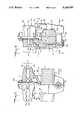
- FIG. 1is a general schematic view in perspective of pin carrier clips mounted on an external fixation bar, which is in addition provided with a device for the lateral displacement of one of the clips.
- FIG. 2shows a clip in a plane parallel to the axis of the bar, the pins being oriented perpendicularly.
- the componentsare shown in section on the right-hand half of FIG. 2, and in side view on the left-hand half.
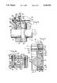
- FIG. 3is a view of the clip in a plane at right angles to the axis of the bar, shown in section on the left-hand half of the figure and in side view on the right-hand half.
- FIG. 4is a view in section, on a larger scale, of the clip shown in FIG. 3.
- FIG. 5is a partly sectional view, in a plane parallel to the axis of the bar, of a variant clip, showing an angle drive means enabling the pins to be oriented in other directions.
- FIG. 6is a variant for the clip according to the invention, in a plane parallel to the axis of the bar, shown in section on the left-hand half of the figure and in side view on the right-hand half.
- FIG. 7is a view of the clip in FIG. 6, in a plane transversal to the bar axis, shown in section on the right-hand half of the figure and in side view on the left-hand half.
- FIG. 8is a sectional view along VIII--VIII in FIG. 6.
- FIG. 1illustrates an external fixation bar 1 of polygonal section, on which are disposed to clips 2 and 3 according to the invention, which are indirectly fastened to a clamp 4 gripping pins 5.
- a continuous external fixation bar 1is shown in the drawings, but it is obvious that as a variant the bar may be one consisting of telescopic elements.
- Each clipis provided with a curved deflection member positioned between the clamp 4 and a jaw 6 surrounding the bar 1 on which it may be fixed by a positioning device 7.
- This curved deflection memberis not shown in the schematic view given in FIG. 1, but will be described in detail later on. It permits the angular pivoting of the clamp 4 in the direction of the arrow A, on the one hand, and the continuous orientation by 0 to 360° of the set of pins relative to the clamping axis 8, in the direction of the arrow B, on the other hand.
- the clip 3 shown in FIG. 1is in addition provided with an angle drive means 9 enabling the clamp 4', and consequently the pins 51, to be turned 90°.
- An angle drive of this kindis for example used when the pins 51' are intended to be inserted into the epiphysis (for example the tibial or femoral head) of a bone whose diaphysis would receive the pins 5.
- the clip 3also permits angular orientation in accordance with the arrow C.
- the arrow Din turn represents the displacement of the clip along the bar.
- a member 10which serves for the displacement of the clip 3 along the bar 1, which may carry linear markings 11, usually graduated in millimeters.
- the displacement member 10consists of a fastening clip 12 comprising two parts pivoted on an axis 13 and is clamped on the bar 1 by a screw 14. It also comprises a support 15 fixed for rotation with the clip 12 and having an opening for the fastening of the head of a feed screw 16, along which is moved a threaded boss 17 integral with a clamp 18 provided with two flanges 19 intended to embrace the side portion of the clip 3.
- the external fixation bar 1, the clamp 4, the jaw 6, the positioning device 7 enabling the clip to be fastened on the bar 1, and also an arrangement 80 for clamping the pins in the direction of the axis 8can be seen again.
- the previously mentioned curved deflection memberis shown under the general reference 40.
- the clamp 4is composed of an upper grip 20 and a lower grip 30, both of which grips have a generally rectangular shape and are provided with a central passage 21, 31 for the clamping arrangement 80.
- the mutually facing surfaces of the gripsare provided with parallel grooves 22, 32 intended to the passage of the pins inserted into the bone.
- the grooves 22 or 32are provided in their central portion with a recess 23 or 33 intended to ensure better anchoring of the pins.
- the upper clamp grip 20is in addition provided with two downwardly projecting side nibs 24 intended to penetrate into corresponding recesses 34 in the lower grip, in such a manner as to prevent the rotation of the grips 20 and 30 in relation to one another.
- the lower grip 30 of the clampis provided in its bottom portion with a circular central boss 35, in which a central frustoconical recess 36, of which the angle is of the order of 7°, is formed.
- the frustoconical recess 36is intended to receive a corresponding frustoconical shoulder 41 on the curved deflection member 40, the central portion of which receives a hollow shaft 42 provided with an external screwthread 43 and an internal shoulder 44 in its end portion (see FIG. 4).
- the hollow shaft 42is usually made of stainless steel and is sealed in the curved deflection member 40 by any means known to those versed in the art (for example screwing or adhesive bonding).
- a collar 45may be provided for support in a corresponding cylindrical opening 46 provided in the top part of the deflection member 40.
- the hollow shaft 42is intended to pass through the central passage 31 in the lower grip 30 and the central passage 21 in the upper grip 20 of the clamp 4.
- the curved deflection member 40has a radius of curvature whose centre is situated beyond the plane of the pins. In its bottom part it is provided with two curved skids 47, which are symmetrical and parallel and each of which has a groove 48 delimiting a curved shoulder 49 in the top part of each skid 47. As can be seen in the drawing, the curved skids 47, and consequently the curved shoulder 49, are disposed parallel to the axis of the bar.
- the curved skids 47are intended to slide along hollows 51 of corresponding curvature, which are formed in a bridge 50 disposed between the parts of jaw 6.
- the central portion 52 of the bridgeis provided with an oblong opening 53 parallel to the skids 47.
- the bridge 50In its bottom portion the bridge 50 is provided with two inclined sides 54 whose slope corresponds to the shape of the bar 1, and with two straight rim portions 55 having at each end an outwardly projecting flange 56 (FIGS. 2 and 3).
- the clamshell type jaw 6has two symmetrical parts, each of them has in its inner portion visible in FIG. 4:
- a curved shoulder 61 and a groove 62which are intended to cooperate respectively with the groove 48 and the shoulder 49 of the deflection member 40;
- each jawis provided above the straight rim portion with lateral recesses 65 intended to receive the lateral flanges 56 of the bridge 50.
- each jawis provided with an opening 66 having an inner rim 67 intended to cooperate with the positioning device 7.
- This positioning device 7will be described with reference to FIG. 4, which is more detailed. It comprises a hollow shaft 70 provided with a head 71 having an opening 72 leading to the outsided and intended to cooperate with a clamping tool, for example a hexagonal opening.
- the diameter of the head 71is such that it penetrates into the opening 66 of the jaw and comes to bear against the inner rim 67. It will be observed that the head 71 is in addition provided with an external circular groove 73 intended to receive a ring 74 of the O-ring type.
- the hollow shaft 70is provided with an internal shoulder 75 and ends in a central internal screwthread 76.
- the positioning device 7also comprises a central shaft 77 having a head 71 identical to that previously described.
- the central shaft 77is provided with an external screwthread intended to cooperate with the internal screwthread 76 of the hollow shaft 70, and is also provided with an internal screwthread 78 intended to receive a cheese-head screw (a British term, which is equivalent to the term “filister head screw” or “pan head screw”) 79.
- the clamping arrangement 80consists of a nut 81 mounted on a washer 82 and intended to be screwed onto the screwthread 43 of the hollow shaft 42 which, as has already been seen, is fastened to the curved deflection member 40.
- a central tube 83has been disposed inside the hollow shaft 42.
- This central tube 83ends at the bottom in a disc 84 and at the top in a central internal screwthread 85.
- the disc 84is fixed to the end of the tube 83 by any means known to those versed in the art. It has a curved shape whose curvature corresponds to that of the central portion 52 of the bridge 50 against which it comes to bear, while the tube 83 passes freely through the oblong opening 53 in the bridge before penetrating into the hollow shaft 42.
- the tube 83is in addition provided with a groove 86 for the insertion of a ring 87 of O-ring type.
- the clamping arrangement 80is completed by a screw 88, whose head 89 has a hexagonal opening and is of such dimensions as to bear against the internal shoulder 44 of the hollow shaft 42.
- the angle drive 9 already schematically indicated in FIG. 1is shown in detail in FIG. 5. It is an elongate member having at its base a collar 91 defining a frustoconical opening 92 whose shape corresponds to the conical shoulder 41 of the curved deflection member 40. At the centre of the collar a through opening 93 permits the passage of the hollow shaft 42 and leads onto a flat 94 intended to cooperate with a clamp nut 95.
- a protuberance 96extends at right angles to the opening 93 and ends in a frustoconical shoulder 97 intended for cooperation with the frustoconical recess 36 formed in the grip 30 of the pin carrier clamp.
- a threaded rod 98is fixed by any known means. The threaded rod 98 is intended to pass through the clamp 4' fastening the pins 5' in a transverse plane relative to the spacer bar, and for this purpose comes into engagement with a nut 99.
- the external fixation bar 1has a polygonal section.
- the bar shown in FIG. 3has two parallel faces 101 and 102 disposed between the pair of jaws 6, each of these faces being followed by a face 103 and 104 inclined at 20° in such a manner as to follow the shape of the corresponding inclined side 54 of the bridge and of the corresponding inclined side 64 of each jaw.
- the clip according to the inventioncan also be fixed on a cylindrical bar.
- an intermediate part 110is added between the jaws, the outer walls of which part correspond to the parallel faces 101 and 102 and also to the inclined faces 103 and 104 already described.
- the connection member 110has two openings 111 and 112 of generally rectangular shape and of dimensions permitting the passage of the disc 84 fixed to the end of the tube 83.
- a slot 113is provided over the entire length of the connection member 110, in such a manner as to give the latter a certain elasticity.
- the connection member 110is provided with an outwardly facing collar, not shown in the drawing, which is intended to hold it in the clip.
- an external fixation bar 100having a circular section, a clamp having an upper grip 120 and a lower grip 130, a jaw 160 for positioning the clip along the bar, a securing device 170 enabling the clip to be fastened on the bar 100, and also an arrangement 180 for clamping the pins 5 can be seen again.
- the curved deflection memberis shown under the general reference 140; it has an arrangement 190 for the angular fixation with respect to the jaw 160.
- the upper and lower clamp grips 120 and 130have a generally rectangular shape and are provided with a central passage 121, 131 for the clamping arrangement 180.
- the mutually facing surfaces of the gripsare provided with parallel grooves 122, 132 intended for the passage of the pins 5 inserted into the bones.
- the upper face of the upper clamp grip 120is provided with a recess 123 for a screw head of the clamping arrangement 180 while its lower face presents two symmetric recesses 124, to prevent the rotation of the grips 120 and 130 in relation to one another, as detailed later on.
- the upper face of the lower clamp grip 130is provided with two recesses 135 for receiving two nibs 136 protruding into the recesses 124 of the upper grip and further receiving two springs 125 intended to spread the grips 120 and 130 one from another, in order to facilitate the introduction of the pins 5.
- the lower face of the lower grip 130has a cylindrical hollow 137 in order to authorize the swivelling of the clamp (and consequently of the pins) with respect to the deflection member 140.
- This deflection member 140presents a cap, the cover 141 of which has a curvature corresponding to the cylindrical hollow 137 in the lower grip.
- the cover 141further presents an oblong opening 142 authorizing the free passage of the clamping arrangement 180.
- the wall 143 of the caphas a cylindrical shape and possesses a slot 144 extending at one of the ends of the opening 142 and defining two protruding wings 145 and 146.
- the jaw 160is not shown in order to authorize the representation of the deflection member 140.
- Its wing 145has a threaded opening 147 and its wing 146 has a passage 148 opening into an external recess 149 intended to receive the fixation arrangement 190 which is transversally disposed with respect to the oblong opening 142 and to the slot 144.
- the jaw 160is in one piece having a generally cylindrical shape; it has a transverse passage 161 for the fixation rod 100, which extends to a slot 162 defining two wings 163 and 164 and authorizing the jaw 160 to be clamped on the bar 100 by means of the clamping arrangement 170 for positioning the jaw along the fixation rod.
- the jaw 160has an upper circular shoulder 165 intended to cooperate with the wall 143 in order to clamp the deflection member 140 by means of the fixation arrangement 190.
- the superior face of the shoulder 165presents an upper recess 166 for the clamping arrangement 180.
- the shoulder 165externally presents a groove 167 intended to receive the fixation arrangement 190 which bounds the deflection member 140 with the jaw 160, and realized on a part of the circumference for reasons given later on.
- the clamping arrangement 170is disposed perpendicular to the slot 162 and is intended to bring closer the wings 163 and 164. It consists in a screw 171 having a head 172 embedded in a recess 168 of the wing 164 and a threaded portion passing through the wing 164 and engaging an internal thread in the wing 163.
- the clamping arrangement 180 of FIGS. 6 and 7consists in a screw 181, the head 182 of which is intended to rest on the recess 123 of the upper grip 120.
- the threaded portion of the screw 181freely passes through the passages 121 and 131 in the upper and lower grips, through the oblong opening 142 and engages in a stud 183, the superior face of which moulds the curvature of the deflection member cover 141.
- the fixation arrangement 190consists in a screw 191, the head 192 of which is intended to rest on the recess 149 of the wing 146.
- the threaded portion of the screw 191freely passes through the passage 148 and engages in the threaded opening 147 in the wing 145.
- screw heads 172, 182 and 192present the same hexagonal opening, to be clamped with the same tool.
- some of these screw headscould present flutes on their periphery, in order to authorize a manual pre-clamping.
- the various components of the clip according to the invention(such as the clip carrier clamp, the deflection member, the jaw, and the angle drive means) have no sharp edges and are made of aluminum or other light alloy in order to limit the weight of the apparatus.
- the clip according to the inventionis assembled in the manner illustrated in the drawing, with or without an angle drive means depending on requirements.
- each set of pins 5is held in a plane by means of the clamp 4 and is positioned relative to the bar 1 by taking advantage of the continuous orientation facilitied of the clamp in the direction of the arrow B, through the relative positioning of the frustoconical recess 36 of the clamp grip 30 and of the corresponding frustoconical shoulder 41 of the curved deflection member 40.
- the nut 81is then locked on the external screwthread 43 of the hollow shaft 42.
- the locking of the angular pivoting of the clamp in the direction of the arrow Acan be achieved in two ways.
- the jaws 6will thus not be clamped against the latter.
- the screw 88is operated to bring its head 89 to bear against the internal shoulder 44 of the hollow shaft 42 and to enable the central tube 83 to be moved upwards.
- the tube 83is fastened to a disc 84 bearing against the central portion 52 of the bridge and thus enabling said bridge 50 to be clamped in relation to the curved deflection member 40, which is thus locked in position.
- the ring 87 of the O-ring type disposed around the central tube 83serves to retain the latter insided the hollow shaft 42 when the screw 88 has not been placed in position.
- the settingis effected in an analogous way as previously described.
- the pins 5are maintained in a plane by means of the clamp grips 120 and 130. It is to be noted that the springs 125 tend to press the cylindrical hollow 137 on the cover 141, thus braking the movement of the clamp on the deflection member.
- the physiciancan separately adjust the swivelling of the clamp with respect to the deflection member, according to the arrow A, and the rotation of the clamp and of the deflection member with respect to the jaw 160, according to the arrow B.
- the clipcan be moved along the bar 100 according to the arrow D and be turned with respect to the bar according to the arrow G, as long as the securing device 170 is not locked.
- securing arrangements 170, 180 and 190could be replaced by devices with a screwing and unscrewing limiter, as described with respect to the variant of FIG. 4.
Landscapes
- Health & Medical Sciences (AREA)
- Orthopedic Medicine & Surgery (AREA)
- Life Sciences & Earth Sciences (AREA)
- Surgery (AREA)
- Medical Informatics (AREA)
- Engineering & Computer Science (AREA)
- Biomedical Technology (AREA)
- Heart & Thoracic Surgery (AREA)
- Molecular Biology (AREA)
- Animal Behavior & Ethology (AREA)
- General Health & Medical Sciences (AREA)
- Public Health (AREA)
- Veterinary Medicine (AREA)
- Nuclear Medicine, Radiotherapy & Molecular Imaging (AREA)
- Surgical Instruments (AREA)
- Clamps And Clips (AREA)
- Flanged Joints, Insulating Joints, And Other Joints (AREA)
- Switches With Compound Operations (AREA)
- Body Structure For Vehicles (AREA)
- Supports Or Holders For Household Use (AREA)
- Medicinal Preparation (AREA)
- Orthopedics, Nursing, And Contraception (AREA)
- Adornments (AREA)
- Finger-Pressure Massage (AREA)
- Sheet Holders (AREA)
- Valve-Gear Or Valve Arrangements (AREA)
- Automobile Manufacture Line, Endless Track Vehicle, Trailer (AREA)
- Materials For Medical Uses (AREA)
- Laminated Bodies (AREA)
- Jigs For Machine Tools (AREA)
- Mutual Connection Of Rods And Tubes (AREA)
- Gripping Jigs, Holding Jigs, And Positioning Jigs (AREA)
Abstract
Description
Claims (17)
Applications Claiming Priority (3)
| Application Number | Priority Date | Filing Date | Title |
|---|---|---|---|
| CH04631/88 | 1988-12-15 | ||
| CH4631/88ACH678485A5 (en) | 1988-12-15 | 1988-12-15 | |
| JP1325779AJPH0640884B2 (en) | 1988-12-15 | 1989-12-15 | Bone pin positioning and fixing device |
Publications (1)
| Publication Number | Publication Date |
|---|---|
| US5160335Atrue US5160335A (en) | 1992-11-03 |
Family
ID=25695947
Family Applications (1)
| Application Number | Title | Priority Date | Filing Date |
|---|---|---|---|
| US07/447,972Expired - LifetimeUS5160335A (en) | 1988-12-15 | 1989-12-08 | Pin holder support |
Country Status (12)
| Country | Link |
|---|---|
| US (1) | US5160335A (en) |
| EP (1) | EP0374093B1 (en) |
| JP (1) | JPH0640884B2 (en) |
| AT (1) | ATE125438T1 (en) |
| CA (1) | CA2005318C (en) |
| CH (1) | CH678485A5 (en) |
| DE (2) | DE68923604T2 (en) |
| DK (1) | DK175033B1 (en) |
| ES (1) | ES2075072T3 (en) |
| FI (1) | FI896005A7 (en) |
| IL (1) | IL92708A (en) |
| NO (1) | NO178746C (en) |
Cited By (76)
| Publication number | Priority date | Publication date | Assignee | Title |
|---|---|---|---|---|
| US5320623A (en)* | 1991-07-16 | 1994-06-14 | Orthofix S.R.1. | Clamping coupling for an external fixator |
| US5391167A (en)* | 1992-09-01 | 1995-02-21 | Ortho-Motion, Inc. | Articulating external fixation device |
| US5397322A (en)* | 1990-08-03 | 1995-03-14 | Jaquet Orthopedie S.A. | Manipulator for external bone fixation devices |
| US5437666A (en)* | 1992-08-24 | 1995-08-01 | Synthes (U.S.A.) | External fixation device for osteosynthesis |
| US5454810A (en)* | 1990-02-05 | 1995-10-03 | Pohl; Anthony P. | External fixation device |
| WO1995031146A1 (en)* | 1994-05-16 | 1995-11-23 | Murray William M | Method and apparatus for machining bone |
| USD373635S (en) | 1995-11-14 | 1996-09-10 | Zimmer, Inc. | External fixation clamp |
| US5662650A (en)* | 1995-05-12 | 1997-09-02 | Electro-Biology, Inc. | Method and apparatus for external fixation of large bones |
| US5676664A (en)* | 1995-11-27 | 1997-10-14 | Zimmer, Inc. | Orthopaedic distractor and/or fixator |
| US5709681A (en)* | 1995-09-19 | 1998-01-20 | Pennig; Dietmar | Device for osteosynthesis |
| DE29619711U1 (en)* | 1996-11-13 | 1998-03-12 | Synthes AG Chur, Chur, Graubünden | Device for repositioning bone fracture fragments |
| US5728096A (en)* | 1994-08-23 | 1998-03-17 | Orthofix S.R.L. | External trochanter splint |
| US5733291A (en)* | 1996-10-10 | 1998-03-31 | Hayes Medical, Incorporated | Long bone alignment tool |
| US5741252A (en)* | 1996-03-25 | 1998-04-21 | Synthes U.S.A. | Adjustable clamp for bone fixation element |
| US5743898A (en)* | 1995-05-12 | 1998-04-28 | Electro-Biology, Inc. | Method and apparatus for external fixation of small bones |
| US5846245A (en)* | 1995-10-20 | 1998-12-08 | New York University | Bone-adjusting device |
| US5891144A (en)* | 1996-05-10 | 1999-04-06 | Jaquet Orthopedie S.A. | External fixator |
| US5961515A (en)* | 1995-03-01 | 1999-10-05 | Smith & Nephew, Inc. | External skeletal fixation system |
| US5976125A (en)* | 1995-08-29 | 1999-11-02 | The Cleveland Clinic Foundation | External distractor/fixator for the management of fractures and dislocations of interphalangeal joints |
| WO1999059489A1 (en) | 1998-05-19 | 1999-11-25 | Synthes Ag Chur | Connecting element for a monolateral external fixation system for traumatology and orthopaedics |
| US6007534A (en)* | 1995-11-20 | 1999-12-28 | Gonzalez; Onofre | Bone stabilizing apparatus |
| US6024745A (en)* | 1997-05-21 | 2000-02-15 | Orthofix, S.R.L. | External minisplint device |
| US6102911A (en)* | 1997-02-13 | 2000-08-15 | Orthofix S.R.L. | Orthopaedic apparatus, particularly for the surgical correction of bone deformities |
| US6159210A (en)* | 1997-01-14 | 2000-12-12 | Research Corporation Technologies, Inc. | Bone fixation pin with rotary cutting tip |
| US6162224A (en)* | 1995-02-15 | 2000-12-19 | Acumed, Inc. | External fixator for repairing fractures of distal radius and wrist |
| US6171309B1 (en) | 1995-02-15 | 2001-01-09 | Acumed, Inc. | External fixator for repairing fractures of distal radius and wrist |
| US6217577B1 (en)* | 1999-01-21 | 2001-04-17 | Medicalplastic S.R.L. | Outer fixing device for orthopedics and traumatology |
| US6235029B1 (en) | 1997-02-14 | 2001-05-22 | Orthofix S.R.L. | Orthopaedic device for the gradual correction of limbs |
| US6409729B1 (en) | 1998-05-19 | 2002-06-25 | Synthes (Usa) | Clamp assembly for an external fixation system |
| KR20020069899A (en)* | 2001-02-28 | 2002-09-05 | 유앤아이 주식회사 | a pin clamp of an external fixator |
| US6464705B2 (en) | 1996-02-23 | 2002-10-15 | D. Barclay Slocum Trust Agreement | Joint support |
| US6565564B2 (en) | 2000-12-14 | 2003-05-20 | Synthes U.S.A. | Multi-pin clamp and rod attachment |
| US20030109879A1 (en)* | 1994-12-05 | 2003-06-12 | Orsak James E. | External fixator for distal radius fractures |
| US20040059331A1 (en)* | 2002-09-17 | 2004-03-25 | Visionmed, L.L.C. | Unilateral fixator |
| US20040097922A1 (en)* | 2002-11-14 | 2004-05-20 | Visionmed, L.L.C. | Method for a using fixator device |
| US20050182406A1 (en)* | 2004-01-23 | 2005-08-18 | Orbay Jorge L. | System for stabilization of fractures of convex articular bone surfaces including subchondral support structure |
| US7004943B2 (en) | 2002-02-04 | 2006-02-28 | Smith & Nephew, Inc. | Devices, systems, and methods for placing and positioning fixation elements in external fixation systems |
| US20060052781A1 (en)* | 2004-08-20 | 2006-03-09 | Stryker Trauma S.A. | Clamp for multiple rod-shaped elements |
| US7048735B2 (en) | 2002-02-04 | 2006-05-23 | Smith & Nephew | External fixation system |
| US7147640B2 (en) | 2003-03-12 | 2006-12-12 | Acumed Llc | External fixator |
| US7261713B2 (en) | 2001-10-09 | 2007-08-28 | Synthes (Usa) | Adjustable fixator |
| US20090018541A1 (en)* | 2007-06-27 | 2009-01-15 | Abraham Lavi | Multi-angle clamp |
| US7507240B2 (en) | 2005-03-18 | 2009-03-24 | Ron Anthon Olsen | Adjustable splint for osteosynthesis |
| CN100518679C (en)* | 2004-03-10 | 2009-07-29 | 辛迪思有限公司 | External fixator for osteosynthesis |
| US7608074B2 (en) | 2003-01-10 | 2009-10-27 | Smith & Nephew, Inc. | External fixation apparatus and method |
| US7731738B2 (en) | 2005-12-09 | 2010-06-08 | Orthopro, Llc | Cannulated screw |
| US7758582B2 (en) | 2002-06-14 | 2010-07-20 | Smith & Nephew, Inc. | Device and methods for placing external fixation elements |
| US7780710B2 (en) | 2004-01-23 | 2010-08-24 | Depuy Products, Inc. | System for stabilization of fractures of convex articular bone surfaces including subchondral support structure |
| US7896886B2 (en) | 2005-01-28 | 2011-03-01 | Depuy Products, Inc. | Nail plate and implantation jig therefor |
| EP2294994A1 (en)* | 2009-09-11 | 2011-03-16 | Stryker Trauma SA | External fixation component |
| US20110082458A1 (en)* | 2009-10-05 | 2011-04-07 | Stryker Trauma Sa | Dynamic External Fixator And Methods For Use |
| US7938850B2 (en) | 2002-05-30 | 2011-05-10 | Depuy Products, Inc. | Nail plate |
| US20120143191A1 (en)* | 2006-12-20 | 2012-06-07 | Brian Foote | Joint fixator |
| US8336867B1 (en) | 2006-09-01 | 2012-12-25 | Chick Workholding Solutions, Inc. | Workholding apparatus having a detachable jaw plate |
| US8454004B1 (en)* | 2006-09-01 | 2013-06-04 | Chick Workholding Solutions, Inc. | Workholding apparatus having a movable jaw member |
| CN103330588A (en)* | 2013-06-24 | 2013-10-02 | 李明 | Minimal invasive fracture restoration and fixing bracket system |
| US8573578B1 (en) | 2006-09-01 | 2013-11-05 | Chick Workholding Solutions, Inc. | Workholding apparatus |
| US8758343B2 (en) | 2005-04-27 | 2014-06-24 | DePuy Synthes Products, LLC | Bone fixation apparatus |
| US8808289B2 (en) | 2010-10-07 | 2014-08-19 | Stryker Trauma Sa | Coupling element for an external fixator |
| US8940020B2 (en) | 2012-04-06 | 2015-01-27 | DePuy Synthes Products, LLC | Rod connector |
| US8945128B2 (en) | 2010-08-11 | 2015-02-03 | Stryker Trauma Sa | External fixator system |
| US9101398B2 (en) | 2012-08-23 | 2015-08-11 | Stryker Trauma Sa | Bone transport external fixation frame |
| US9227303B1 (en) | 2006-09-01 | 2016-01-05 | Chick Workholding Solutions, Inc. | Workholding apparatus |
| US20160022315A1 (en)* | 2013-01-21 | 2016-01-28 | Tecres S.P.A. | External fixing device, for treating bone fractures |
| US9308026B2 (en)* | 2011-04-20 | 2016-04-12 | Ramon L. Ruiz | Distractor device including multiple diameter internal post and related methods |
| US9352451B1 (en) | 2013-05-02 | 2016-05-31 | Chick Workholding Solutions, Inc. | Workholding apparatus |
| US9393045B2 (en) | 2013-03-15 | 2016-07-19 | Biomet Manufacturing, Llc. | Clamping assembly for external fixation system |
| US20160235421A1 (en)* | 2015-02-18 | 2016-08-18 | Clemson University | Positioning Bracket for Multiple Bone Tunnel Drill Guides |
| US9770272B2 (en) | 2012-12-12 | 2017-09-26 | Wright Medical Technology, Inc. | Orthopedic compression/distraction device |
| US9872706B1 (en)* | 2014-05-14 | 2018-01-23 | Devise Ortho Inc. | External fixation device |
| WO2019245406A1 (en)* | 2018-06-21 | 2019-12-26 | Дильшад Даларисович ШАРАФИЕВ | Apparatus for external osteosynthesis |
| CN112617990A (en)* | 2019-09-24 | 2021-04-09 | 云南欧铂斯医疗科技有限公司 | Multi-arm multi-freedom fracture repositor |
| US11141196B2 (en) | 2010-08-11 | 2021-10-12 | Stryker European Operations Holdings Llc | External fixator system |
| US11399870B2 (en)* | 2019-12-31 | 2022-08-02 | The Third Hospital Of Hebei Medical University | Automatic traction device for lower limb fracture osteosynthesis |
| US11737786B2 (en) | 2019-12-31 | 2023-08-29 | Orthopediatrics Corp. | Multiple track system for positioning of bone segments |
| IT202200024405A1 (en)* | 2022-11-25 | 2024-05-25 | Citieffe Srl | EXTERNAL FIXING DEVICE CLAMP |
Families Citing this family (4)
| Publication number | Priority date | Publication date | Assignee | Title |
|---|---|---|---|---|
| NL9101054A (en)* | 1991-06-18 | 1993-01-18 | Breunis Van Den Brink | BONE FIXING DEVICE. |
| NL9301738A (en)* | 1993-10-08 | 1995-05-01 | Agnes Mathilde Termaten Geb Va | Device for mutually fixing bone parts. |
| JP4594268B2 (en)* | 2006-04-07 | 2010-12-08 | 有限会社メディコ・インターメディア | Bone extender |
| JP4902626B2 (en)* | 2008-11-28 | 2012-03-21 | ジンテーズ ゲゼルシャフト ミト ベシュレンクテル ハフツング | Jaw for unilateral external fixation system for trauma and orthopedics |
Citations (10)
| Publication number | Priority date | Publication date | Assignee | Title |
|---|---|---|---|---|
| US2393694A (en)* | 1945-04-10 | 1946-01-29 | Otto S Kirschner | Surgical apparatus |
| GB2077847A (en)* | 1980-06-12 | 1981-12-23 | Nat Res Dev | Connector Assemblies |
| GB2110094A (en)* | 1981-11-27 | 1983-06-15 | Per Helland | Fracture fixing device |
| FR2520607A3 (en)* | 1982-01-29 | 1983-08-05 | Bossi Enrico | EXTERNAL FIXER FOR MONOLATERAL OSTEOSYNTHESIS |
| FR2557933A1 (en)* | 1984-01-10 | 1985-07-12 | Srebot | Articulation device for assembling several elements, especially for an external fixture intended for osteosynthesis. |
| FR2559380A1 (en)* | 1984-02-13 | 1985-08-16 | Orthofix Srl | EXTERNAL ORTHOPEDIC AXIAL FASTENING DEVICE |
| US4600000A (en)* | 1982-09-16 | 1986-07-15 | Edwards Charles C | External fixation system |
| FR2579688A2 (en)* | 1984-01-10 | 1986-10-03 | Srebot | Joint for assembling several elements, especially for an external fastening device intended for osteosynthesis |
| US4662365A (en)* | 1982-12-03 | 1987-05-05 | Ortopedia Gmbh | Device for the external fixation of bone fragments |
| US4848368A (en)* | 1988-04-25 | 1989-07-18 | Kronner Richard F | Universal external fixation frame assembly |
Family Cites Families (1)
| Publication number | Priority date | Publication date | Assignee | Title |
|---|---|---|---|---|
| EP0314021A3 (en)* | 1987-10-26 | 1989-12-06 | Howmedica GmbH | Fixing device for parts of bones |
- 1988
- 1988-12-15CHCH4631/88Apatent/CH678485A5/frnot_activeIP Right Cessation
- 1989
- 1989-11-29ATAT89810912Tpatent/ATE125438T1/ennot_activeIP Right Cessation
- 1989-11-29DEDE68923604Tpatent/DE68923604T2/ennot_activeExpired - Lifetime
- 1989-11-29ESES89810912Tpatent/ES2075072T3/ennot_activeExpired - Lifetime
- 1989-11-29EPEP89810912Apatent/EP0374093B1/ennot_activeExpired - Lifetime
- 1989-12-06DKDK198906141Apatent/DK175033B1/ennot_activeIP Right Cessation
- 1989-12-08USUS07/447,972patent/US5160335A/ennot_activeExpired - Lifetime
- 1989-12-12DEDE8914594Upatent/DE8914594U1/ennot_activeExpired - Lifetime
- 1989-12-13CACA002005318Apatent/CA2005318C/ennot_activeExpired - Fee Related
- 1989-12-14NONO895019Apatent/NO178746C/enunknown
- 1989-12-14ILIL9270889Apatent/IL92708A/ennot_activeIP Right Cessation
- 1989-12-15JPJP1325779Apatent/JPH0640884B2/ennot_activeExpired - Lifetime
- 1989-12-15FIFI896005Apatent/FI896005A7/ennot_activeApplication Discontinuation
Patent Citations (11)
| Publication number | Priority date | Publication date | Assignee | Title |
|---|---|---|---|---|
| US2393694A (en)* | 1945-04-10 | 1946-01-29 | Otto S Kirschner | Surgical apparatus |
| GB2077847A (en)* | 1980-06-12 | 1981-12-23 | Nat Res Dev | Connector Assemblies |
| GB2110094A (en)* | 1981-11-27 | 1983-06-15 | Per Helland | Fracture fixing device |
| US4488542A (en)* | 1981-11-27 | 1984-12-18 | Per Helland | External setting and correction device for the treatment of bone fractures |
| FR2520607A3 (en)* | 1982-01-29 | 1983-08-05 | Bossi Enrico | EXTERNAL FIXER FOR MONOLATERAL OSTEOSYNTHESIS |
| US4600000A (en)* | 1982-09-16 | 1986-07-15 | Edwards Charles C | External fixation system |
| US4662365A (en)* | 1982-12-03 | 1987-05-05 | Ortopedia Gmbh | Device for the external fixation of bone fragments |
| FR2557933A1 (en)* | 1984-01-10 | 1985-07-12 | Srebot | Articulation device for assembling several elements, especially for an external fixture intended for osteosynthesis. |
| FR2579688A2 (en)* | 1984-01-10 | 1986-10-03 | Srebot | Joint for assembling several elements, especially for an external fastening device intended for osteosynthesis |
| FR2559380A1 (en)* | 1984-02-13 | 1985-08-16 | Orthofix Srl | EXTERNAL ORTHOPEDIC AXIAL FASTENING DEVICE |
| US4848368A (en)* | 1988-04-25 | 1989-07-18 | Kronner Richard F | Universal external fixation frame assembly |
Cited By (130)
| Publication number | Priority date | Publication date | Assignee | Title |
|---|---|---|---|---|
| US5454810A (en)* | 1990-02-05 | 1995-10-03 | Pohl; Anthony P. | External fixation device |
| US5397322A (en)* | 1990-08-03 | 1995-03-14 | Jaquet Orthopedie S.A. | Manipulator for external bone fixation devices |
| US5320623A (en)* | 1991-07-16 | 1994-06-14 | Orthofix S.R.1. | Clamping coupling for an external fixator |
| US5437666A (en)* | 1992-08-24 | 1995-08-01 | Synthes (U.S.A.) | External fixation device for osteosynthesis |
| US5391167A (en)* | 1992-09-01 | 1995-02-21 | Ortho-Motion, Inc. | Articulating external fixation device |
| US5616146A (en)* | 1994-05-16 | 1997-04-01 | Murray; William M. | Method and apparatus for machining bone to fit an orthopedic surgical implant |
| WO1995031146A1 (en)* | 1994-05-16 | 1995-11-23 | Murray William M | Method and apparatus for machining bone |
| US5728096A (en)* | 1994-08-23 | 1998-03-17 | Orthofix S.R.L. | External trochanter splint |
| US6793655B2 (en) | 1994-12-05 | 2004-09-21 | Smith & Nephew, Inc. | External fixator for distal radius fractures |
| US20030109879A1 (en)* | 1994-12-05 | 2003-06-12 | Orsak James E. | External fixator for distal radius fractures |
| US6171309B1 (en) | 1995-02-15 | 2001-01-09 | Acumed, Inc. | External fixator for repairing fractures of distal radius and wrist |
| US6162224A (en)* | 1995-02-15 | 2000-12-19 | Acumed, Inc. | External fixator for repairing fractures of distal radius and wrist |
| US5961515A (en)* | 1995-03-01 | 1999-10-05 | Smith & Nephew, Inc. | External skeletal fixation system |
| US5662650A (en)* | 1995-05-12 | 1997-09-02 | Electro-Biology, Inc. | Method and apparatus for external fixation of large bones |
| US6171308B1 (en) | 1995-05-12 | 2001-01-09 | Kirk Jay Bailey | Method and apparatus for external fixation of large bones |
| US5743898A (en)* | 1995-05-12 | 1998-04-28 | Electro-Biology, Inc. | Method and apparatus for external fixation of small bones |
| US5976125A (en)* | 1995-08-29 | 1999-11-02 | The Cleveland Clinic Foundation | External distractor/fixator for the management of fractures and dislocations of interphalangeal joints |
| US5709681A (en)* | 1995-09-19 | 1998-01-20 | Pennig; Dietmar | Device for osteosynthesis |
| US5846245A (en)* | 1995-10-20 | 1998-12-08 | New York University | Bone-adjusting device |
| US6019769A (en)* | 1995-10-20 | 2000-02-01 | New York University And Howmedica, Inc. | Bone-adjusting device |
| USD373635S (en) | 1995-11-14 | 1996-09-10 | Zimmer, Inc. | External fixation clamp |
| US6007534A (en)* | 1995-11-20 | 1999-12-28 | Gonzalez; Onofre | Bone stabilizing apparatus |
| US5676664A (en)* | 1995-11-27 | 1997-10-14 | Zimmer, Inc. | Orthopaedic distractor and/or fixator |
| US6464705B2 (en) | 1996-02-23 | 2002-10-15 | D. Barclay Slocum Trust Agreement | Joint support |
| US5741252A (en)* | 1996-03-25 | 1998-04-21 | Synthes U.S.A. | Adjustable clamp for bone fixation element |
| US5891144A (en)* | 1996-05-10 | 1999-04-06 | Jaquet Orthopedie S.A. | External fixator |
| US5733291A (en)* | 1996-10-10 | 1998-03-31 | Hayes Medical, Incorporated | Long bone alignment tool |
| DE29619711U1 (en)* | 1996-11-13 | 1998-03-12 | Synthes AG Chur, Chur, Graubünden | Device for repositioning bone fracture fragments |
| US6159210A (en)* | 1997-01-14 | 2000-12-12 | Research Corporation Technologies, Inc. | Bone fixation pin with rotary cutting tip |
| US6102911A (en)* | 1997-02-13 | 2000-08-15 | Orthofix S.R.L. | Orthopaedic apparatus, particularly for the surgical correction of bone deformities |
| US6235029B1 (en) | 1997-02-14 | 2001-05-22 | Orthofix S.R.L. | Orthopaedic device for the gradual correction of limbs |
| US6024745A (en)* | 1997-05-21 | 2000-02-15 | Orthofix, S.R.L. | External minisplint device |
| US6409729B1 (en) | 1998-05-19 | 2002-06-25 | Synthes (Usa) | Clamp assembly for an external fixation system |
| WO1999059489A1 (en) | 1998-05-19 | 1999-11-25 | Synthes Ag Chur | Connecting element for a monolateral external fixation system for traumatology and orthopaedics |
| US6500177B1 (en) | 1998-05-19 | 2002-12-31 | Synthes (Usa) | Telescopic body for an external fixation system |
| US6217577B1 (en)* | 1999-01-21 | 2001-04-17 | Medicalplastic S.R.L. | Outer fixing device for orthopedics and traumatology |
| EP1021992A3 (en)* | 1999-01-21 | 2003-01-15 | Medicalplastic S.r.L. | External fixator for orthopaedics and traumatology |
| US7699848B2 (en) | 2000-12-14 | 2010-04-20 | Synthes Usa, Llc | Multipin clamp and rod attachment |
| US20030191468A1 (en)* | 2000-12-14 | 2003-10-09 | Synthes U.S.A. | Multipin clamp and rod attachment |
| US6565564B2 (en) | 2000-12-14 | 2003-05-20 | Synthes U.S.A. | Multi-pin clamp and rod attachment |
| US7041103B2 (en) | 2000-12-14 | 2006-05-09 | Synthes (Usa) | Multipin clamp and rod attachment |
| KR20020069899A (en)* | 2001-02-28 | 2002-09-05 | 유앤아이 주식회사 | a pin clamp of an external fixator |
| US7261713B2 (en) | 2001-10-09 | 2007-08-28 | Synthes (Usa) | Adjustable fixator |
| US8382757B1 (en) | 2001-10-09 | 2013-02-26 | Synthes Usa, Llc | Adjustable fixator |
| US7887537B2 (en) | 2002-02-04 | 2011-02-15 | Smith & Nephew, Inc. | External fixation system |
| US7004943B2 (en) | 2002-02-04 | 2006-02-28 | Smith & Nephew, Inc. | Devices, systems, and methods for placing and positioning fixation elements in external fixation systems |
| US7048735B2 (en) | 2002-02-04 | 2006-05-23 | Smith & Nephew | External fixation system |
| US7938850B2 (en) | 2002-05-30 | 2011-05-10 | Depuy Products, Inc. | Nail plate |
| US7758582B2 (en) | 2002-06-14 | 2010-07-20 | Smith & Nephew, Inc. | Device and methods for placing external fixation elements |
| US7282052B2 (en) | 2002-09-17 | 2007-10-16 | Ebi, L.P. | Unilateral fixator |
| US20070282338A1 (en)* | 2002-09-17 | 2007-12-06 | Ebi, L.P. | Unilateral fixator |
| US8388619B2 (en) | 2002-09-17 | 2013-03-05 | Sixfix Inc. | Unilateral fixator |
| US20040059331A1 (en)* | 2002-09-17 | 2004-03-25 | Visionmed, L.L.C. | Unilateral fixator |
| US8419732B2 (en) | 2002-11-14 | 2013-04-16 | Sixfix, Inc. | Method for using a fixator device |
| US20110103676A1 (en)* | 2002-11-14 | 2011-05-05 | Extraortho, Inc. | Method for using a fixator device |
| US20040097922A1 (en)* | 2002-11-14 | 2004-05-20 | Visionmed, L.L.C. | Method for a using fixator device |
| US8382755B2 (en) | 2003-01-10 | 2013-02-26 | Smith & Nephew, Inc. | External fixation apparatus and method |
| US7608074B2 (en) | 2003-01-10 | 2009-10-27 | Smith & Nephew, Inc. | External fixation apparatus and method |
| US7147640B2 (en) | 2003-03-12 | 2006-12-12 | Acumed Llc | External fixator |
| US20050182406A1 (en)* | 2004-01-23 | 2005-08-18 | Orbay Jorge L. | System for stabilization of fractures of convex articular bone surfaces including subchondral support structure |
| US7744638B2 (en) | 2004-01-23 | 2010-06-29 | Depuy Products, Inc. | System for stabilization of fractures of convex articular bone surfaces including subchondral support structure |
| US7780710B2 (en) | 2004-01-23 | 2010-08-24 | Depuy Products, Inc. | System for stabilization of fractures of convex articular bone surfaces including subchondral support structure |
| CN100518679C (en)* | 2004-03-10 | 2009-07-29 | 辛迪思有限公司 | External fixator for osteosynthesis |
| US20060052781A1 (en)* | 2004-08-20 | 2006-03-09 | Stryker Trauma S.A. | Clamp for multiple rod-shaped elements |
| US7618417B2 (en) | 2004-08-20 | 2009-11-17 | Stryker Trauma S.A. | Clamp for multiple rod shaped elements |
| US7896886B2 (en) | 2005-01-28 | 2011-03-01 | Depuy Products, Inc. | Nail plate and implantation jig therefor |
| US7927341B2 (en) | 2005-01-28 | 2011-04-19 | Depuy Products, Inc. | Nail plate and jig therefor |
| US7588571B2 (en) | 2005-03-18 | 2009-09-15 | Ron Anthon Olsen | Adjustable splint for osteosynthesis with modular joint |
| US7507240B2 (en) | 2005-03-18 | 2009-03-24 | Ron Anthon Olsen | Adjustable splint for osteosynthesis |
| US7575575B2 (en) | 2005-03-18 | 2009-08-18 | Ron Anthon Olsen | Adjustable splint for osteosynthesis with modular components |
| US8758343B2 (en) | 2005-04-27 | 2014-06-24 | DePuy Synthes Products, LLC | Bone fixation apparatus |
| US7731738B2 (en) | 2005-12-09 | 2010-06-08 | Orthopro, Llc | Cannulated screw |
| US8905392B1 (en) | 2006-09-01 | 2014-12-09 | Chick Workholding Solutions, Inc. | Workholding apparatus having a detachable jaw plate |
| US8454004B1 (en)* | 2006-09-01 | 2013-06-04 | Chick Workholding Solutions, Inc. | Workholding apparatus having a movable jaw member |
| US8336867B1 (en) | 2006-09-01 | 2012-12-25 | Chick Workholding Solutions, Inc. | Workholding apparatus having a detachable jaw plate |
| US10040173B1 (en) | 2006-09-01 | 2018-08-07 | Chick Workholding Solutions, Inc. | Workholding apparatus having a detachable jaw plate |
| US9227303B1 (en) | 2006-09-01 | 2016-01-05 | Chick Workholding Solutions, Inc. | Workholding apparatus |
| US8573578B1 (en) | 2006-09-01 | 2013-11-05 | Chick Workholding Solutions, Inc. | Workholding apparatus |
| US20120143191A1 (en)* | 2006-12-20 | 2012-06-07 | Brian Foote | Joint fixator |
| US8147491B2 (en)* | 2007-06-27 | 2012-04-03 | Vilex In Tennessee, Inc. | Multi-angle clamp |
| US20090018541A1 (en)* | 2007-06-27 | 2009-01-15 | Abraham Lavi | Multi-angle clamp |
| US20110066151A1 (en)* | 2009-09-11 | 2011-03-17 | Stryker Trauma Sa | External fixation component |
| CN102018556A (en)* | 2009-09-11 | 2011-04-20 | 史赛克创伤公司 | External fixation component |
| EP2294994A1 (en)* | 2009-09-11 | 2011-03-16 | Stryker Trauma SA | External fixation component |
| CN102018556B (en)* | 2009-09-11 | 2014-10-15 | 史赛克创伤公司 | External fixation component |
| US8172840B2 (en) | 2009-09-11 | 2012-05-08 | Stryker Trauma Sa | External fixation component |
| US8858555B2 (en) | 2009-10-05 | 2014-10-14 | Stryker Trauma Sa | Dynamic external fixator and methods for use |
| US20110082458A1 (en)* | 2009-10-05 | 2011-04-07 | Stryker Trauma Sa | Dynamic External Fixator And Methods For Use |
| US10285734B2 (en) | 2010-08-11 | 2019-05-14 | Stryker European Holdings I, Llc | External fixator system |
| US9839445B2 (en) | 2010-08-11 | 2017-12-12 | Stryker European Holdings I, Llc | External fixator system |
| US8945128B2 (en) | 2010-08-11 | 2015-02-03 | Stryker Trauma Sa | External fixator system |
| US11141196B2 (en) | 2010-08-11 | 2021-10-12 | Stryker European Operations Holdings Llc | External fixator system |
| US9220533B2 (en) | 2010-08-11 | 2015-12-29 | Stryker Trauma Sa | External fixator system |
| US9730730B2 (en) | 2010-08-11 | 2017-08-15 | Stryker European Holdings I, Llc | External fixator system |
| US10080585B2 (en) | 2010-08-11 | 2018-09-25 | Stryker European Holdings I, Llc | External fixator system |
| US12035944B2 (en) | 2010-08-11 | 2024-07-16 | Stryker European Operations Holdings Llc | External fixator system |
| US10376285B2 (en) | 2010-08-11 | 2019-08-13 | Stryker European Holdings I, Llc | External fixator system |
| US8808289B2 (en) | 2010-10-07 | 2014-08-19 | Stryker Trauma Sa | Coupling element for an external fixator |
| US20160220287A1 (en)* | 2011-04-20 | 2016-08-04 | Ramon L. Ruiz | Distractor device including multiple diameter internal post and related methods |
| US9308026B2 (en)* | 2011-04-20 | 2016-04-12 | Ramon L. Ruiz | Distractor device including multiple diameter internal post and related methods |
| US10492840B2 (en)* | 2011-04-20 | 2019-12-03 | Ramon L. Ruiz | Distractor device including multiple diameter internal post and related methods |
| US8940020B2 (en) | 2012-04-06 | 2015-01-27 | DePuy Synthes Products, LLC | Rod connector |
| US10405888B2 (en) | 2012-08-23 | 2019-09-10 | Stryker European Holdings I, Llc | Bone transport external fixation frame |
| US9101398B2 (en) | 2012-08-23 | 2015-08-11 | Stryker Trauma Sa | Bone transport external fixation frame |
| US11090086B2 (en) | 2012-08-23 | 2021-08-17 | Stryker European Operations Holdings Llc | Bone transport external fixation frame |
| US11744616B2 (en) | 2012-08-23 | 2023-09-05 | Stryker European Operations Holdings Llc | Bone transport external fixation frame |
| US9820775B2 (en) | 2012-08-23 | 2017-11-21 | Styker European Holdings I, LLC | Bone transport external fixation frame |
| US9770272B2 (en) | 2012-12-12 | 2017-09-26 | Wright Medical Technology, Inc. | Orthopedic compression/distraction device |
| US10631900B2 (en) | 2012-12-12 | 2020-04-28 | Wright Medical Technology, Inc. | Orthopedic compression/distraction device |
| US20160022315A1 (en)* | 2013-01-21 | 2016-01-28 | Tecres S.P.A. | External fixing device, for treating bone fractures |
| US9750538B2 (en)* | 2013-01-21 | 2017-09-05 | Tecres S.P.A. | External fixing device, for treating bone fractures |
| US10299830B2 (en) | 2013-03-15 | 2019-05-28 | Biomet Manufacturing, Llc | Clamping assembly for external fixation system |
| US9393045B2 (en) | 2013-03-15 | 2016-07-19 | Biomet Manufacturing, Llc. | Clamping assembly for external fixation system |
| US9463045B2 (en) | 2013-03-15 | 2016-10-11 | Biomet Manufacturing, Llc | Polyaxial pivot housing for external fixation system |
| US9827011B2 (en) | 2013-03-15 | 2017-11-28 | Biomet Manufacturing, Llc | Polyaxial pivot housing for external fixation system |
| US9352451B1 (en) | 2013-05-02 | 2016-05-31 | Chick Workholding Solutions, Inc. | Workholding apparatus |
| CN103330588A (en)* | 2013-06-24 | 2013-10-02 | 李明 | Minimal invasive fracture restoration and fixing bracket system |
| US20220323113A1 (en)* | 2014-05-14 | 2022-10-13 | Orthopediatrics Corp. | External fixation device |
| US12161366B2 (en)* | 2014-05-14 | 2024-12-10 | Orthopediatrics Corp. | External fixation device |
| US10299831B2 (en) | 2014-05-14 | 2019-05-28 | Devise Ortho Inc. | External fixation device |
| US9872706B1 (en)* | 2014-05-14 | 2018-01-23 | Devise Ortho Inc. | External fixation device |
| US11207104B2 (en)* | 2014-05-14 | 2021-12-28 | Orthopediatrics Corp. | External fixation device |
| US20160235421A1 (en)* | 2015-02-18 | 2016-08-18 | Clemson University | Positioning Bracket for Multiple Bone Tunnel Drill Guides |
| US10869680B2 (en)* | 2015-02-18 | 2020-12-22 | Clemson University | Positioning bracket for multiple bone tunnel drill guides |
| WO2019245406A1 (en)* | 2018-06-21 | 2019-12-26 | Дильшад Даларисович ШАРАФИЕВ | Apparatus for external osteosynthesis |
| CN112617990A (en)* | 2019-09-24 | 2021-04-09 | 云南欧铂斯医疗科技有限公司 | Multi-arm multi-freedom fracture repositor |
| US11399870B2 (en)* | 2019-12-31 | 2022-08-02 | The Third Hospital Of Hebei Medical University | Automatic traction device for lower limb fracture osteosynthesis |
| US11737786B2 (en) | 2019-12-31 | 2023-08-29 | Orthopediatrics Corp. | Multiple track system for positioning of bone segments |
| IT202200024405A1 (en)* | 2022-11-25 | 2024-05-25 | Citieffe Srl | EXTERNAL FIXING DEVICE CLAMP |
| EP4374807A1 (en) | 2022-11-25 | 2024-05-29 | Citieffe S.r.L. | Clamp for external fixation device |
Also Published As
| Publication number | Publication date |
|---|---|
| NO178746B (en) | 1996-02-19 |
| ES2075072T3 (en) | 1995-10-01 |
| DE8914594U1 (en) | 1990-02-08 |
| NO895019L (en) | 1990-06-18 |
| JPH0640884B2 (en) | 1994-06-01 |
| CH678485A5 (en) | 1991-09-30 |
| DE68923604T2 (en) | 1996-01-25 |
| FI896005A0 (en) | 1989-12-15 |
| ATE125438T1 (en) | 1995-08-15 |
| IL92708A (en) | 1994-01-25 |
| DK175033B1 (en) | 2004-05-03 |
| EP0374093B1 (en) | 1995-07-26 |
| DK614189A (en) | 1990-06-16 |
| DK614189D0 (en) | 1989-12-06 |
| DE68923604D1 (en) | 1995-08-31 |
| EP0374093A1 (en) | 1990-06-20 |
| CA2005318C (en) | 1996-05-21 |
| JPH03193045A (en) | 1991-08-22 |
| FI896005A7 (en) | 1990-06-16 |
| CA2005318A1 (en) | 1990-06-15 |
| NO178746C (en) | 1996-05-29 |
| NO895019D0 (en) | 1989-12-14 |
Similar Documents
| Publication | Publication Date | Title |
|---|---|---|
| US5160335A (en) | Pin holder support | |
| US5393161A (en) | External fixator | |
| US5261912A (en) | Implant for an osteosynthesis device, in particular for spinal column correction | |
| US4745913A (en) | Apparatus for the stabilization of bone fractures | |
| EP0425783B1 (en) | Pedicle screw clamp | |
| AU645780B2 (en) | Multifunctional rachis osteosynthesis device | |
| US5267999A (en) | Clamp for use in spinal surgery | |
| US5360429A (en) | Device for straightening, fixing, compressing, and elongating cervical vertebrae | |
| US4730608A (en) | External bone-anchoring fixator | |
| US8679117B2 (en) | Bolt and tool with anti-torque features | |
| US6413257B1 (en) | Clamping connector for spinal fixation systems | |
| US4365624A (en) | External bone-anchoring element | |
| US6030388A (en) | Top tightening bone fixation apparatus | |
| AU704134B2 (en) | Spine construct with band clamp | |
| US7147639B2 (en) | Disposable external fixation device | |
| CA2204449C (en) | External fixator | |
| US6280445B1 (en) | Multi-axial bone anchor system | |
| US6123707A (en) | Reduction instrument | |
| US5601551A (en) | Geared external fixator | |
| US5207676A (en) | External fixator with controllable damping | |
| EP0626836A4 (en) | Variable angle screw for spinal implant system. | |
| IE64430B1 (en) | External fixator with controllable damping | |
| GB2114891A (en) | External bone-pin splint | |
| JPH09192143A (en) | Connection element for fixing rod to pedicle screw |
Legal Events
| Date | Code | Title | Description |
|---|---|---|---|
| AS | Assignment | Owner name:JAQUET ORTHOPEDIE S.A., SWITZERLAND Free format text:ASSIGNMENT OF ASSIGNORS INTEREST.;ASSIGNOR:WAGENKNECHT, MARCEL H.;REEL/FRAME:005693/0261 Effective date:19910412 | |
| FEPP | Fee payment procedure | Free format text:PAYOR NUMBER ASSIGNED (ORIGINAL EVENT CODE: ASPN); ENTITY STATUS OF PATENT OWNER: LARGE ENTITY | |
| STCF | Information on status: patent grant | Free format text:PATENTED CASE | |
| FPAY | Fee payment | Year of fee payment:4 | |
| FEPP | Fee payment procedure | Free format text:PAYER NUMBER DE-ASSIGNED (ORIGINAL EVENT CODE: RMPN); ENTITY STATUS OF PATENT OWNER: LARGE ENTITY Free format text:PAYOR NUMBER ASSIGNED (ORIGINAL EVENT CODE: ASPN); ENTITY STATUS OF PATENT OWNER: LARGE ENTITY | |
| FPAY | Fee payment | Year of fee payment:8 | |
| AS | Assignment | Owner name:STRYKER TRAUMA SA, SWITZERLAND Free format text:CHANGE OF NAME;ASSIGNOR:JAQUET ORTHOPEDIE SA;REEL/FRAME:011712/0636 Effective date:19991206 | |
| AS | Assignment | Owner name:STRYKER TRAUMA SA, SWITZERLAND Free format text:DISSOLUTION DOCUMENT;ASSIGNOR:STRYKER TRAUMA SA;REEL/FRAME:014990/0394 Effective date:20020628 Owner name:STRYKER TRAUMA SA, SWITZERLAND Free format text:MERGER;ASSIGNOR:STRYKER TRAUMA SA;REEL/FRAME:014990/0372 Effective date:20020625 | |
| FPAY | Fee payment | Year of fee payment:12 |