US5160076A - Ticket dispensing device and method - Google Patents
Ticket dispensing device and methodDownload PDFInfo
- Publication number
- US5160076A US5160076AUS07/492,650US49265090AUS5160076AUS 5160076 AUS5160076 AUS 5160076AUS 49265090 AUS49265090 AUS 49265090AUS 5160076 AUS5160076 AUS 5160076A
- Authority
- US
- United States
- Prior art keywords
- ticket
- tickets
- panel
- barrier
- housing
- Prior art date
- Legal status (The legal status is an assumption and is not a legal conclusion. Google has not performed a legal analysis and makes no representation as to the accuracy of the status listed.)
- Expired - Lifetime
Links
Images


Classifications
- G—PHYSICS
- G07—CHECKING-DEVICES
- G07F—COIN-FREED OR LIKE APPARATUS
- G07F17/00—Coin-freed apparatus for hiring articles; Coin-freed facilities or services
- G07F17/42—Coin-freed apparatus for hiring articles; Coin-freed facilities or services for ticket printing or like apparatus, e.g. apparatus for dispensing of printed paper tickets or payment cards
- Y—GENERAL TAGGING OF NEW TECHNOLOGICAL DEVELOPMENTS; GENERAL TAGGING OF CROSS-SECTIONAL TECHNOLOGIES SPANNING OVER SEVERAL SECTIONS OF THE IPC; TECHNICAL SUBJECTS COVERED BY FORMER USPC CROSS-REFERENCE ART COLLECTIONS [XRACs] AND DIGESTS
- Y10—TECHNICAL SUBJECTS COVERED BY FORMER USPC
- Y10T—TECHNICAL SUBJECTS COVERED BY FORMER US CLASSIFICATION
- Y10T225/00—Severing by tearing or breaking
- Y10T225/10—Methods
- Y10T225/16—Transversely of continuously fed work
- Y—GENERAL TAGGING OF NEW TECHNOLOGICAL DEVELOPMENTS; GENERAL TAGGING OF CROSS-SECTIONAL TECHNOLOGIES SPANNING OVER SEVERAL SECTIONS OF THE IPC; TECHNICAL SUBJECTS COVERED BY FORMER USPC CROSS-REFERENCE ART COLLECTIONS [XRACs] AND DIGESTS
- Y10—TECHNICAL SUBJECTS COVERED BY FORMER USPC
- Y10T—TECHNICAL SUBJECTS COVERED BY FORMER US CLASSIFICATION
- Y10T225/00—Severing by tearing or breaking
- Y10T225/20—Severing by manually forcing against fixed edge
- Y10T225/23—Zigzag-folded supply package
Definitions
- This inventionrelates to ticket dispensing devices and methods, and particularly to ticket vending machines. More particularly, the invention relates to lottery ticket dispensing and vending machines and methods.
- the machineshould deliver the number of tickets for which the customer pays, and it should not cut or mutilate the tickets. It should be particularly reliable in operation, and it should not allow the customer to pull tickets out of the machine without paying for them.
- Such ticketsusually are supplied in panels with the tickets separated from one another by perforation lines, and the tickets are supplied preferably in a stack of fan-folded panels. Such tickets are unusually difficult to feed accurately and tear apart. Therefore, many prior ticket dispensers have resorted to cutting the tickets apart.
- the dispensing mechanism of the above-identified prior patent applicationhas been used with some success in a multiple ticket-vending machine which will accept bills and issue a number of tickets corresponding to the amount paid by the customer.
- the ticketsare moved past a window as they are being dispensed so that the customer can see the tickets through the windows, both before and while they are being dispensed.
- That vending machineis shown in U.S. patent application Ser. No. 312,111, filed Feb. 17, 1989, in the name of Robert L. Burr.
- a ticket dispensing device and methodin which a ticket strip or panel is bent through a substantial angle along a perforated line, and one or more tickets ahead of the bend are projected out of an opening in the machine housing.
- the remaining tickets in the panelare held inside the machine so that the customer can grasp the projecting ticket or tickets and easily tear them free of the remaining tickets in the panel.
- a tearing barrieris provided in the machine, and the bent perforation is held closely adjacent to an edge of the barrier so that the projecting ticket or tickets can be pulled against the barrier to facilitate tearing.
- a curved guidebe provided, and means are provided for thrusting the ticket panel longitudinally against the guide so as to cause it to buckle and bend. Then, when the angle of the lead ticket has changed sufficiently due to the bending, the ticket is ejected through the outlet opening in the dispensing machine.
- a gatebe provided to move to the outlet opening to block it, and away from the opening where it provides a surface to urge and guide the ticket out of the outlet while it is being pushed forward by the feed mechanism.
- the gate meansis swung back towards the outlet opening to push the ticket out and hold the remaining tickets in the panel firmly in place to facilitate tearing.
- the result of the inventionis that tickets are almost invariably torn only along perforations, so that tickets are not cut or torn in two or mutilated. Furthermore, the mechanism is greatly simplified because no power-driven means are needed to cut or burst the tickets apart; instead, the customer supplies the tearing power and the mechanism which otherwise would be needed is eliminated.
- the dispensing mechanism of the inventionis particularly beneficial due to its compact size and simplicity when used in a multiple-window ticket vending machine constructed in accordance with the present invention. Because they are more compact, more dispensing mechanisms can be housed in the same size housing, at a considerably lower cost than in the past.
- FIG. 1is a perspective view of a multiple ticket lottery ticket vending machine constructed in accordance with the present invention
- FIG. 2is a right-side perspective, partially schematic view of a ticket dispensing mechanism constructed in accordance with the present invention
- FIG. 3is a left-side perspective, partially broken-away view of the device shown in FIG. 2;
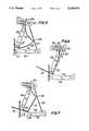
- FIG. 4is a side-elevation, partially schematic view of the internal construction of the ticket dispensing device shown in FIGS. 2 and 3;
- FIGS. 5, 6 and 7are simplified side-elevation views, similar to that of FIG. 4, showing the ticket dispensing mechanism at various different times during the dispensing of tickets.
- FIG. 8is a perspective, partially broken-away view of a portion of the mechanism shown in FIGS. 2 through 4.
- FIG. 9is a top-plan view of a ticket-tearing barrier of the device shown in FIGS. 2 through 4;
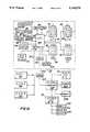
- FIG. 10is a schematic circuit diagram of an operating circuit of a vending machine and a computerized vending system using many vending machines such as the one shown in FIG. 1;
- FIG. 11is a partially cross-sectional broken-away view taken along line 11--11 of FIG. 8.
- FIG. 1shows a lottery ticket vending machine 20 utilizing the present invention.
- the machine 20includes a housing 22, two rows 24 and 26 of windows displaying different lottery tickets, a bill acceptor 28, and a message display 30.
- the top row 24 of windowsincludes four windows 32-35, four corresponding push-buttons 36-39 mounted in a projecting panel 40, and four corresponding dispensing openings or slots 42-44. Two instant-winner lottery tickets 68 and 70 are shown issuing from the slot 44.
- the bottom row 26 of windowsincludes four windows 45-48, four push-buttons 50-53 in a panel 49, and four dispensing slots 54-57.
- the purchasercan see each of the eight different tickets through the windows and can read the legends and the prize information contained on the tickets.
- the purchaserhas selected the ticket to purchase he or she inserts a $1.00, $5.00, $10.00 or $20.00 bill in the bill acceptor 28, and pushes the appropriate one of the eight buttons to select which type of ticket is to be dispensed. The tickets then automatically are issued from the slot for the selected ticket.
- the ticketsare issued in groups. That is, for example, if the customer inserts a five dollar bill and each of the tickets costs one dollar, a panel of five tickets will be dispensed. The customer then grasps the ticket group, pulls on it, and tears the group of tickets off.
- the ticket panelsmove downwardly past the windows so that the customer can see the tickets moving.
- a vending machine constructed in accordance with the present inventioncan have any number of dispensing windows and mechanisms desired, such as one, two, four, six, or eight or more.
- FIG. 2is a perspective view of a dispensing mechanism 60 constructed in accordance with the present invention.
- One such dispenseris located behind each of the windows in FIG. 1.
- the device 60includes a housing having a pair of side panels 62 and 64 with internal spacers providing transverse support, and a front panel 69 with an outlet slot with an outlet opening 71.
- Fan-folded panels of lottery tickets 66are stored in a pile 64 in the housing.
- the panels of ticketsare pulled upwardly from the pile 64, over the top of the unit 60, between a pair of relatively soft guide rollers 65 and 67, and vertically downwardly.
- the vertical array of ticketsis covered by the transparent material of one of the windows when used in a vending machine like the one shown in FIG. 1.
- the panel of ticketsis driven downwardly by a main feed roller 102 (see FIG. 4, not shown in FIG. 2) operating against an idler 74.
- the feed roller 102is driven by a sprocket 76 and a chain 80 driven by a small sprocket 78 which is driven by a stepping motor 82.
- the stepping motoris shown in dashed outline in FIG. 2 and is housed in the housing of the dispensing mechanism.
- the main feed roller 102which is driven by the motor 82 of FIG. 2 is mounted to rotate on bearings 108 (also see FIGS. 8 and 11) which are force-fitted into holes in the side panels 62 and 64.
- the feed roller 102mates with an idler roller 100.
- the strip or panel 66 of ticketsis driven downwardly by the roller 102 between edge guides 94 which are positioned on opposite sides 62 and 64 of the housing of the ticket dispensing device, and move between a pair of rolls 96 and 98.
- Roll 98is an optional imprinter roll which imprints information on the rear surface of each ticket. Such information can include the vending location, a vendor's name, or other such information.
- Roller 96is an idler.
- the panel 66is fed downwardly over a guide member 106 which has a top edge 109, a curved upper surface, and a sharp tearing edge 107.
- the guide memberis inclined at an angle to vertical.
- the lower or leading edge 124 of the ticket panelabuts against the front portion of the curved upper surface 118 of each of four guide members 116 (see FIG. 8). Only one guide member 116 is shown in FIG. 4.
- the guide members 116are arranged so that the front edge of each is spaced from the bottom edge of the barrier member 106 to leave a relatively thin gap 122 between the two members.
- the sharp lower edge 107 of the barrier member 106serves as a tearing edge against which tickets are torn loose. Tickets are issued outwardly through the gap 122 and the outlet opening 71 in the front panel 69 of the dispensing mechanism.
- a gate mechanismis shown in FIG. 4.
- the gate mechanismincludes a gate panel 92 which is secured by fasteners 114 to the lower portion 112 of a gate arm 90.
- a gate panel 92which is secured by fasteners 114 to the lower portion 112 of a gate arm 90.
- Eachis rotatably mounted on the outer surface of the bearing 108 which mounts the drive roller 102 in the housing.
- the gate panelholds the gate arms in place.
- the gate mechanismcan swing freely about the axis of the feed roller 102.
- the four guide members 116are held together by screws 126 and 128 driven into the threaded ends of support rods 152 and 154 Which pass through holes in each of the four guide members.
- the guide members 116preferably are made of a plastic material such as Delrin.
- the upper surface 118 of eachis smooth.
- FIG. 4two alternative drive mechanisms for the gate are shown. For ease of illustration, they are both shown in FIG. 4 as if they were inside the housing of the dispensing mechanism, whereas actually they are outside of the housing.
- One drive mechanismincludes a cam 86 secured to a shaft 87.
- the cambears against cam follower arms 88 and 89.
- FIG. 3the shaft 87 is driven by a stepper motor 72.
- the cam 86 and the cam follower arms 88 and 89actually are outside the housing of the dispensing mechanism.
- FIGS. 2 and 3, as well as FIG. 8,show that the gate arms 90 extend outside of the housing through holes 84 and 85 in the side panels 64 and 62.
- a second alternative drive meansis a spring 138 attached to the arm 88 at one end and secured at 142 to a fastener which is adjustably mounted in a slot 144 in the wall 64 to adjust the spring tension.
- the spring 138 and the cam 86need not be used together, but are alternative forms of drive means for the gate mechanism.
- the spring 138is used to close the gate, and the cam to open it. Otherwise, the cam and spring are alternative means for operating the gate.
- one end of the gate panel 92moves back and forth in the large opening 84 in the left side panel 64 of the device 60.
- the stepping motor 72is shown in dashed outline. It rotates shaft 87 to drive the cam 86 and lift the follower arms up and let them down.
- FIGS. 4 and 8The cam follower structure is shown in FIGS. 4 and 8, as well as in FIG. 3. For ease of illustration, it is shown in FIGS. 4 and 8 as if it were attached to the right side of the dispenser mechanism rather than the left side.
- the followerincludes a base bar 135 which is fastened by screws 134 and 136 to the gate arm 90.
- the bar 135has a central semi-circular cut-out to fit over the bearing surface 103.
- the arms 88, 89are steel rods threaded at one end into holes in the base bar 135.
- the gate mechanismwhen driven by the cam mechanism is as follows. Referring again to FIG. 4, the gate mechanism is shown in solid lines all the way to the left in its "home” position where it blocks the outlet gap 122 through which tickets are issued. The follower 88 and the cam 86 are shown in solid lines in the positions they have when the gate is thus closed.
- An upper extension arm 110is attached to the arm 90 and has a thin blade 111 which passes between the lamp and photocell of a photodetector 113 which produces an electrical signal when the gate reaches its home position.
- the gateis opened by the force of each bending ticket which pushes it to the right and rotates the gate mechanism counterclockwise to open it.
- the slot 144makes it possible to secure the fastener 142 at varying positions in the slot to vary the spring tension to accommodate tickets of varying thickness and weight. This is an optional feature which may be needed when tickets of relatively thin paper are being dispensed.
- the thin papermay not be stiff enough to push the gate open against the rather heavy spring tension needed to close the gate when tickets of stiffer, heavier materials are dispensed. Therefore, lower spring tensions can be used to enable the tickets to push the gate open.
- a third means of driving the gateis a hybrid of the foregoing. Only follower arm 88 is used. The cam 86 rotates to open the gate, and the spring 138 closes it. The cam 86 is moved axially or returned to its starting position very rapidly in order to allow the spring 138 to do its work.
- the cam drivehas the advantage that it positively opens the gate every time, whereas the material of the tickets may not be up to the task all the time.
- the spring drivehas the advantage that it is simple and inexpensive.
- the hybrid driveuses the best features of both; the positive drive of the cam to open the gate, and the smoothness of operation resulting from using the spring return instead of the fluttering drive of the cam drive stepping motor.
- the drive roller 102has a polyethylene surface of about 55 shorr durometer hardness for good drive traction.
- the idlers 96 and 100are made of aluminum. Idler 100 is biased towards drive roller 102 by a very simple spring bias device. Two short pieces 97 of 0.055 diameter piano wire are used as springs, one at each end of the roller 100 (only one spring 97 is shown in FIG. 4). One end of each wire is wrapped around a post 95 projecting from one of the side walls 62 and 64. The wire then is bent to bear against axles 99 and 101 of idlers 96 and 100 to provide spring thrust against the axle of the idler 100. Each spring thus provides around two pounds of thrust, for a total of four pounds of thrust to hold the idler 100 tightly against the feed roller 102 and grip the tickets firmly.
- the thrust provided by this arrangementcan be varied simply by changing the diameter of the piano wire.
- FIG. 4also is shown, in simplified form, in FIGS. 5, 6 and 7 at different positions during the dispensing of tickets.
- the ticket dispensing operationstarts with the panel of tickets 66 in the position shown in FIG. 4, with its leading edge 124 abutting against the curved upper surface of the guide members 116, at a point near the outlet 122.
- the drive roller 102Upon receiving instructions to issue a ticket, the drive roller 102 rotates and forces the ticket panel downwardly. The gate then proceeds to open and move to the right (counterclockwise), under either the pushing force of the ticket material itself (in the case where the spring 138 alone operates the gate), or by the action of the cam 86 which is being driven by the stepping motor 72 shown in FIG. 3.
- FIG. 5shows what has happened after the ticket panel has been driven downwardly by a distance somewhat less than the width of one ticket. As it is shown in FIG. 4, the ticket panel in its initial position is bent slightly to the right by the curvature of the guide member 106.
- the panel of ticketsis held firmly in place, whereas the bend 148 of the ticket is snugly fitted up against the sharp edge 107 of the barrier member 106, with the lead ticket and the panel being at about 90 degrees angle relative to one another. It then is an easy matter for the customer to grasp the protruding ticket 68, pull it outwardly, tear the ticket free along the perforated line 148.
- the same procedureis followed repeatedly the proper number of times to issue the proper number of tickets. For example, the same procedure is repeated ten times if the customer buys ten tickets, and the customer can tear off the strip of ten tickets when the machine is finished dispensing. Thus, the cutting or tearing of each ticket is avoided. This saves time and wear and tear on the dispenser.
- the continued feeding of the ticket panelcauses the panel to bend at the next perforation line 150.
- the corner 150bears against the stationary gate panel 92 and forces the corner 148 to move upwardly along the curved guide and out all the way to the gap 122 so that the bend 148 is adjacent the sharp edge 107.
- the corner 150then slides downwardly along the barrier 92, and the second ticket 70 in the string then moves outwardly through the outlet opening.
- the electronic control system of the inventioncounts each ticket as it is issued, so that his pulling a string of tickets will end with the gate mechanism 92 closing and preventing him from obtaining any more tickets than he has paid for.
- the gate panel 92has lower corner cut-outs 160 and notches 162 which form three short broad projections 164 which extend slightly into the spaces between adjacent guide members 116. This insures that the edge of a ticket will not accidentally slip into a gap or junction between the lower edge of the guide panel 92 and the guide members 116.
- FIG. 9which is a top plan view of the barrier member 106
- the cutting edge 107is concave.
- the tearingwill start at one of the two edges of the ticket, rather than elsewhere. This promotes tearing cleanly along the perforation, and minimizes accidental tearing elsewhere.
- FIG. 10shows a ticket vending system including a number of vending units 20 and a central computer 204.
- Each unit 20has a microprocessor whose CPU 190 is shown in FIG. 10.
- the bill receiver or acceptor 28outputs a signal which indicates the denomination of the bill and its authenticity.
- the CPUcomputes the amount of credit due to the customer and displays it on the LED display 30 so that the customer knows how much credit he or she has at any given moment.
- the bill receiveris adapted to accept bills in denomination of $1.00, $5.00, $10.00 and $20.00 in U.S. currency, or other multiple denominations of the currency of other countries.
- the selector switches 36-39 and 50-53are shown as an array 166.
- a keypadcan be used for ticket selection instead, if desired.
- the switch for the selected type of ticketthen is operated by the customer to select one of the eight games available, and the bill receiver indicates the number of lottery tickets to be issued. This information is operated upon by the CPU 190 and is used to cause the proper number of tickets to be issued from the selected dispenser 60. (For ease of illustration, only four dispensers are shown in FIG. 10). Then the amount of credit shown on the display 30 is reduced by one unit as each ticket is issued so that the customer can see that he is being charged the proper amount for each ticket. The customer then can select other windows and other numbers of tickets, if desired.
- Counting the number of ticketsis done by counting the number of steps taken by the stepping motor 82 which drives the feed roll 102. For this purpose, stepping pulses are sent to the CPU 190 for counting.
- the gate mechanismopens and closes for the dispensing of every ticket, the number of pulses of the photodetector 113 (FIG. 4) can be counted to count the number of tickets dispensed. This has the advantage of not requiring the machine to store data regarding varying ticket lengths, and would not require changes for different ticket lengths.
- the microprocessorsends a signal to start the cam drive motor 72 when the ticket drive motor 82 (FIG. 2) is started.
- the cam drive motorstops when the microprocessor counts a pre-determined number of steps taken by the motor 72. Then, after a pre-determined number of steps of the ticket drive 82 motor has been counted, indicating a movement of the ticket panel 66 by a desired distance, the cam drive motor 72 is started again to close the gate. The motor 72 stops when the detector 113 detects that the gate has actually closed. The cycle then is repeated for the next ticket, until all tickets in the order have been dispensed.
- the feed stepping motor 82has a shaft position encoder 83 including a lamp and photocell detector cooperating with a disc with slits to give signals indicating the actual movement of the stepping motor. This is done to ensure that the drive motor actually moves the feed roller 102. When the feed roller has not moved, this is an indication that there is a jam in the machine and that service is required.
- a photodetector 79detects and signals when the cam returns to its starting point.
- Communication between the vending units 20 and the central computer 204preferably is through telephone lines 202 by means of a modem 203, or an optional dial-up modem 192 in each of the units 10.
- a group of four or more vending unitscan be operated in a master-slave relationship with one unit 20 being the master and three units 194, 196 and 198 being connected by cable as slaves to the master unit. In this manner, there is communication with the central computer only through the master unit. This reduces the number of telephone lines needed to one, and reduces hardware costs in the slave units.
- the master-slave groupingsare convenient to use when multiple vending machine are located close to one another, as in a single building.
- FIG. 10shows, in the lower portion, another vending unit 20 with three slaves 210, 212 and 214. Still another vending unit 20 without any slaves is shown to the right and above the central computer 204 in FIG. 10.
- a keyboard 206 and a printer 208are connected to the central computer at the same location as the computer so that ticket agents can input and output the information necessary to control the vending units and check on their operation and security.
- a printer 208is located inside of each vending machine 20. Such a printer prints a record of all transactions and data regarding operation of the machine, and can be used by the agent servicing the machine for accounting and other purposes which have been disclosed in the above-identified co-pending patent applications.
- One of the advantages of the inventionis that, within wide limits, adjustments need not be made in the mechanism for tickets of different lengths.
- the mechanism shown in FIGS. 2-7adjusts automatically to dispense tickets of a variety of different lengths. For example, ticket lengths between one inch and over two inches can be accommodated without adjustment.
- a service keypad 191is located internally in the housing of the vending machine 20 to facilitate servicing. If counting of tickets dispensed is done on the basis of accumulated length of tickets fed, then an adjustment can be input with the keypad 191.
- the machine 20optionally can have an electric advertising sign (not shown).
- the wording of the advertising signcan be changed at will, preferable from the central computer 204. It is typically a LED display. It can be stationary or moving, as is well-known in the art.
- the programming of the microprocessor in the vending machineadvises a customer by way of the display 30 when the mechanism dispensing a particular one of the game tickets is inoperative, and then will advise the customer to chose another game.
- the bill receiver or acceptor 28will not accept any currency if all games are inoperative.
- the ticket dispensing mechanismis relatively simple and compact and inexpensive to manufacture. Yet it is fast-operating, and protects against unauthorized removal of tickets without payment. It accommodates different tickets of different thicknesses and lengths.
- the mechanismreduces the incidence of ticket mutilation to a very low level. Furthermore, tickets are issued in strips, rather than singly, thus avoiding the need to sever every ticket from the next one. Yet, this is done without significant danger that the customer will be able to pull more tickets out of the machine then he has paid for.
Landscapes
- Physics & Mathematics (AREA)
- General Physics & Mathematics (AREA)
- Ticket-Dispensing Machines (AREA)
- Vending Machines For Individual Products (AREA)
- Control Of Vending Devices And Auxiliary Devices For Vending Devices (AREA)
- Confectionery (AREA)
Abstract
Description
Claims (22)
Priority Applications (8)
| Application Number | Priority Date | Filing Date | Title |
|---|---|---|---|
| US07/492,650US5160076A (en) | 1990-03-13 | 1990-03-13 | Ticket dispensing device and method |
| JP3506415AJPH06503907A (en) | 1990-03-13 | 1991-03-13 | Ticketing machine and ticketing method |
| AU75413/91AAU7541391A (en) | 1990-03-13 | 1991-03-13 | Ticket dispensing device and method |
| EP91906482AEP0521056B1 (en) | 1990-03-13 | 1991-03-13 | Ticket dispensing device and method |
| CA002078145ACA2078145C (en) | 1990-03-13 | 1991-03-13 | Ticket dispensing device and method |
| PCT/US1991/001738WO1991013734A1 (en) | 1990-03-13 | 1991-03-13 | Ticket dispensing device and method |
| AT91906482TATE172659T1 (en) | 1990-03-13 | 1991-03-13 | DEVICE AND METHOD FOR CARD ISSUING |
| DE69130420TDE69130420T2 (en) | 1990-03-13 | 1991-03-13 | DEVICE AND METHOD FOR DISTRIBUTING CARD |
Applications Claiming Priority (1)
| Application Number | Priority Date | Filing Date | Title |
|---|---|---|---|
| US07/492,650US5160076A (en) | 1990-03-13 | 1990-03-13 | Ticket dispensing device and method |
Publications (1)
| Publication Number | Publication Date |
|---|---|
| US5160076Atrue US5160076A (en) | 1992-11-03 |
Family
ID=23957076
Family Applications (1)
| Application Number | Title | Priority Date | Filing Date |
|---|---|---|---|
| US07/492,650Expired - LifetimeUS5160076A (en) | 1990-03-13 | 1990-03-13 | Ticket dispensing device and method |
Country Status (8)
| Country | Link |
|---|---|
| US (1) | US5160076A (en) |
| EP (1) | EP0521056B1 (en) |
| JP (1) | JPH06503907A (en) |
| AT (1) | ATE172659T1 (en) |
| AU (1) | AU7541391A (en) |
| CA (1) | CA2078145C (en) |
| DE (1) | DE69130420T2 (en) |
| WO (1) | WO1991013734A1 (en) |
Cited By (31)
| Publication number | Priority date | Publication date | Assignee | Title |
|---|---|---|---|---|
| US5845256A (en)* | 1993-08-19 | 1998-12-01 | John B. Pescitelli | Interactive self-service vending system |
| US5950898A (en)* | 1997-09-26 | 1999-09-14 | Instant Technologies, Incorporated | Lottery ticket dispensing apparatus |
| WO1999052691A1 (en)* | 1998-04-14 | 1999-10-21 | On Point Technology Systems | Ticket dispensing modules and method |
| USD441227S1 (en) | 2000-03-09 | 2001-05-01 | On-Point Technology Systems | Counter top lottery ticket dispenser |
| WO2001075806A1 (en)* | 2000-04-05 | 2001-10-11 | Instant Technologies, Incorporated | Lottery ticket dispensing apparatus |
| US20010045456A1 (en)* | 2000-02-02 | 2001-11-29 | Fred Smith | Combination fuel dispensing and lottery ticket dispensing method and apparatus |
| US20030120381A1 (en)* | 2001-11-16 | 2003-06-26 | Perin Joseph C. | Item vending machine and method |
| US6609644B1 (en)* | 1997-09-26 | 2003-08-26 | Instant Technologies, Inc. | Method of dispensing perforated tickets |
| US20030233168A1 (en)* | 1998-08-03 | 2003-12-18 | Interlott Technologies, Inc. | Item vending machine and method |
| US20040000572A1 (en)* | 2002-06-28 | 2004-01-01 | Interlott Technologies, Inc. | Ticket dispensing apparatus and method |
| USD500420S1 (en) | 2003-07-24 | 2005-01-04 | Gtech Corporation | Lottery ticket dispenser |
| USD500616S1 (en) | 2003-07-24 | 2005-01-11 | Gtech Corporation | Lottery ticket dispenser |
| USD501227S1 (en) | 2003-07-24 | 2005-01-25 | Gtech Corporation | Counter top lottery ticket dispenser |
| US20050059463A1 (en)* | 2003-07-01 | 2005-03-17 | Mark Gilmore | System and method for dispensing tickets |
| USD503744S1 (en) | 2003-07-24 | 2005-04-05 | Gtech Corporation | Lottery ticket dispenser |
| US20050181924A1 (en)* | 2003-07-07 | 2005-08-18 | Raimond Demers | Cutterless dunnage converter and method |
| US20060035698A1 (en)* | 1998-04-14 | 2006-02-16 | Roberts Brian J | Gaming device and method |
| US20060071046A1 (en)* | 1998-04-14 | 2006-04-06 | Roberts Brian J | Ticket dispensing modules and method |
| US7032793B2 (en) | 1998-04-14 | 2006-04-25 | Gtech Corporation | Ticket dispensing device, installation and displays |
| US7364058B2 (en) | 1997-09-26 | 2008-04-29 | Scientific Games International, Inc. | Ticket dispensing apparatus |
| US7381132B2 (en) | 1998-04-14 | 2008-06-03 | Gtech Corporation | Gaming system and method |
| US20080145070A1 (en)* | 2002-08-12 | 2008-06-19 | Futurelogic, Inc. | Paper motion detector in a gaming machine |
| US20090152292A1 (en)* | 2007-12-14 | 2009-06-18 | Intralot, Inc. | Multi-channel perforated ticket separation mechanism |
| US20090163263A1 (en)* | 2007-12-19 | 2009-06-25 | Scientific Games International, Inc. | Method and System for Multiple In-Lane Lottery Ticket Sales at a Retail Establishment |
| US8534524B2 (en) | 2010-10-08 | 2013-09-17 | Gtech Corporation | Perforated ticket dispensing machine |
| US8714552B1 (en)* | 2012-10-31 | 2014-05-06 | E-Max Gaming Corporation | Ticket dispenser |
| US10229466B2 (en) | 2015-07-17 | 2019-03-12 | Scientific Games International, Inc. | Method and system for enhanced lottery ticket accounting and sales at a retail establishment level |
| US10373443B2 (en) | 2016-06-21 | 2019-08-06 | Scientific Games International, Inc. | Method and system for enhanced lottery ticket activation and sale at a retail establishment with subsequent billing and accountability of sold tickets |
| US10672234B2 (en) | 2015-07-17 | 2020-06-02 | Scientific Games International, Inc. | Method and system for enhanced lottery ticket accounting and sales with smart bin dispensers at a retail establishment |
| US20220114841A1 (en)* | 2020-10-14 | 2022-04-14 | Scientific Games International, Inc. | Lottery Ticket Dispensing Unit with a Shuttle Separator Device |
| EP3506221B1 (en)* | 2017-12-15 | 2023-08-30 | Scientific Games, LLC | Smart bin lottery ticket dispenser with modular printer bin |
Families Citing this family (3)
| Publication number | Priority date | Publication date | Assignee | Title |
|---|---|---|---|---|
| AUPN600195A0 (en)* | 1995-10-17 | 1995-11-09 | Lottery Products Pty Ltd | Ticket dispensing apparatus |
| ITMI20091984A1 (en)* | 2009-11-12 | 2011-05-13 | Autotex Italia S R L | METHOD AND EQUIPMENT FOR INSTANTANEOUS DISTRIBUTION OF TICKETS |
| FR3143017A1 (en) | 2022-12-08 | 2024-06-14 | Michel Gelin | Selective paper or sachet dispenser |
Citations (16)
| Publication number | Priority date | Publication date | Assignee | Title |
|---|---|---|---|---|
| US961075A (en)* | 1909-08-04 | 1910-06-07 | Louis Gelarie | Ticket-holder. |
| US1339823A (en)* | 1919-02-13 | 1920-05-11 | Paul C Harbaugh | Ticket-dispensing device |
| US1813935A (en)* | 1929-02-18 | 1931-07-14 | Lance Packing Company | Vending machine for bulk edibles |
| US2657750A (en)* | 1947-07-16 | 1953-11-03 | Gen Register Corp | Ticket storage and issuing equipment |
| US2865699A (en)* | 1954-12-20 | 1958-12-23 | William B Fitzgerald | Stamp vending machines |
| US3627183A (en)* | 1970-02-06 | 1971-12-14 | Vern K Mason | Ticket dispenser device |
| US3935978A (en)* | 1975-02-03 | 1976-02-03 | Arnold W. G. Larson | Ticket dispensing apparatus |
| US4032004A (en)* | 1975-07-09 | 1977-06-28 | Francis William Coates | Ticket dispensing arrangement |
| US4094451A (en)* | 1976-11-04 | 1978-06-13 | Granite State Machine Co., Inc. | Lottery ticket dispenser for break-resistant web material |
| US4140259A (en)* | 1977-09-12 | 1979-02-20 | Frank Kostka | Ticket dispenser |
| US4157670A (en)* | 1977-07-27 | 1979-06-12 | Rowe International, Inc. | Ticket vending head |
| US4272001A (en)* | 1979-10-15 | 1981-06-09 | Stephen Horniak | Ticket dispenser |
| US4716799A (en)* | 1986-08-12 | 1988-01-05 | Syntech International, Inc. | Ticket dispensing machine and method |
| US4738384A (en)* | 1986-06-05 | 1988-04-19 | Tigner Calvin L | Dispenser |
| US4858806A (en)* | 1988-02-01 | 1989-08-22 | Schafer Christopher E | Ticket display and dispenser |
| US4982337A (en)* | 1987-12-03 | 1991-01-01 | Burr Robert L | System for distributing lottery tickets |
- 1990
- 1990-03-13USUS07/492,650patent/US5160076A/ennot_activeExpired - Lifetime
- 1991
- 1991-03-13AUAU75413/91Apatent/AU7541391A/ennot_activeAbandoned
- 1991-03-13EPEP91906482Apatent/EP0521056B1/ennot_activeExpired - Lifetime
- 1991-03-13WOPCT/US1991/001738patent/WO1991013734A1/enactiveIP Right Grant
- 1991-03-13DEDE69130420Tpatent/DE69130420T2/ennot_activeExpired - Lifetime
- 1991-03-13ATAT91906482Tpatent/ATE172659T1/ennot_activeIP Right Cessation
- 1991-03-13JPJP3506415Apatent/JPH06503907A/enactivePending
- 1991-03-13CACA002078145Apatent/CA2078145C/ennot_activeExpired - Lifetime
Patent Citations (16)
| Publication number | Priority date | Publication date | Assignee | Title |
|---|---|---|---|---|
| US961075A (en)* | 1909-08-04 | 1910-06-07 | Louis Gelarie | Ticket-holder. |
| US1339823A (en)* | 1919-02-13 | 1920-05-11 | Paul C Harbaugh | Ticket-dispensing device |
| US1813935A (en)* | 1929-02-18 | 1931-07-14 | Lance Packing Company | Vending machine for bulk edibles |
| US2657750A (en)* | 1947-07-16 | 1953-11-03 | Gen Register Corp | Ticket storage and issuing equipment |
| US2865699A (en)* | 1954-12-20 | 1958-12-23 | William B Fitzgerald | Stamp vending machines |
| US3627183A (en)* | 1970-02-06 | 1971-12-14 | Vern K Mason | Ticket dispenser device |
| US3935978A (en)* | 1975-02-03 | 1976-02-03 | Arnold W. G. Larson | Ticket dispensing apparatus |
| US4032004A (en)* | 1975-07-09 | 1977-06-28 | Francis William Coates | Ticket dispensing arrangement |
| US4094451A (en)* | 1976-11-04 | 1978-06-13 | Granite State Machine Co., Inc. | Lottery ticket dispenser for break-resistant web material |
| US4157670A (en)* | 1977-07-27 | 1979-06-12 | Rowe International, Inc. | Ticket vending head |
| US4140259A (en)* | 1977-09-12 | 1979-02-20 | Frank Kostka | Ticket dispenser |
| US4272001A (en)* | 1979-10-15 | 1981-06-09 | Stephen Horniak | Ticket dispenser |
| US4738384A (en)* | 1986-06-05 | 1988-04-19 | Tigner Calvin L | Dispenser |
| US4716799A (en)* | 1986-08-12 | 1988-01-05 | Syntech International, Inc. | Ticket dispensing machine and method |
| US4982337A (en)* | 1987-12-03 | 1991-01-01 | Burr Robert L | System for distributing lottery tickets |
| US4858806A (en)* | 1988-02-01 | 1989-08-22 | Schafer Christopher E | Ticket display and dispenser |
Cited By (51)
| Publication number | Priority date | Publication date | Assignee | Title |
|---|---|---|---|---|
| US5845256A (en)* | 1993-08-19 | 1998-12-01 | John B. Pescitelli | Interactive self-service vending system |
| US7364058B2 (en) | 1997-09-26 | 2008-04-29 | Scientific Games International, Inc. | Ticket dispensing apparatus |
| US5950898A (en)* | 1997-09-26 | 1999-09-14 | Instant Technologies, Incorporated | Lottery ticket dispensing apparatus |
| US6669071B1 (en) | 1997-09-26 | 2003-12-30 | Instant Technologies, Incorporated | Lottery ticket dispensing apparatus |
| WO2000046002A1 (en)* | 1997-09-26 | 2000-08-10 | Instant Technologies, Incorporated | Lottery ticket dispensing apparatus |
| US6609644B1 (en)* | 1997-09-26 | 2003-08-26 | Instant Technologies, Inc. | Method of dispensing perforated tickets |
| US7850257B2 (en) | 1998-04-14 | 2010-12-14 | Roberts Brian J | Ticket dispensing device, installation and displays |
| US7381132B2 (en) | 1998-04-14 | 2008-06-03 | Gtech Corporation | Gaming system and method |
| EP1102662A4 (en)* | 1998-04-14 | 2006-08-30 | Interlott Technologies Inc | CARD OUTPUT MODULE, AND METHOD FOR CARD EDITION |
| US7032793B2 (en) | 1998-04-14 | 2006-04-25 | Gtech Corporation | Ticket dispensing device, installation and displays |
| US7665394B2 (en)* | 1998-04-14 | 2010-02-23 | Gtech Corporation | Ticket dispensing modules and method |
| US6932258B1 (en) | 1998-04-14 | 2005-08-23 | Gtech Corporation | Gaming device and method |
| WO1999052691A1 (en)* | 1998-04-14 | 1999-10-21 | On Point Technology Systems | Ticket dispensing modules and method |
| US20060071046A1 (en)* | 1998-04-14 | 2006-04-06 | Roberts Brian J | Ticket dispensing modules and method |
| US6726077B2 (en) | 1998-04-14 | 2004-04-27 | Gtech Corporation | Ticket dispensing modules and method |
| US20060035698A1 (en)* | 1998-04-14 | 2006-02-16 | Roberts Brian J | Gaming device and method |
| US20030233168A1 (en)* | 1998-08-03 | 2003-12-18 | Interlott Technologies, Inc. | Item vending machine and method |
| US7548797B2 (en) | 1998-08-03 | 2009-06-16 | Gtech Corporation | Item vending machine and method |
| US20010045456A1 (en)* | 2000-02-02 | 2001-11-29 | Fred Smith | Combination fuel dispensing and lottery ticket dispensing method and apparatus |
| USD448956S1 (en) | 2000-03-09 | 2001-10-09 | Interlott Technologies, Inc. | Counter top lottery ticket dispenser |
| USD441227S1 (en) | 2000-03-09 | 2001-05-01 | On-Point Technology Systems | Counter top lottery ticket dispenser |
| USD448957S1 (en) | 2000-03-09 | 2001-10-09 | Interlott Technologies, Inc. | Counter top lottery ticket dispenser |
| WO2001075806A1 (en)* | 2000-04-05 | 2001-10-11 | Instant Technologies, Incorporated | Lottery ticket dispensing apparatus |
| US20030120381A1 (en)* | 2001-11-16 | 2003-06-26 | Perin Joseph C. | Item vending machine and method |
| US7047104B2 (en) | 2001-11-16 | 2006-05-16 | Giech Corporation | Item vending machine and method |
| US20040000572A1 (en)* | 2002-06-28 | 2004-01-01 | Interlott Technologies, Inc. | Ticket dispensing apparatus and method |
| US20080145070A1 (en)* | 2002-08-12 | 2008-06-19 | Futurelogic, Inc. | Paper motion detector in a gaming machine |
| US20050059463A1 (en)* | 2003-07-01 | 2005-03-17 | Mark Gilmore | System and method for dispensing tickets |
| US7756742B2 (en) | 2003-07-01 | 2010-07-13 | Scientific Games International, Inc. | System and method for dispensing tickets |
| US7186208B2 (en)* | 2003-07-07 | 2007-03-06 | Ranpak Corp. | Cutterless dunnage converter and method |
| US20050181924A1 (en)* | 2003-07-07 | 2005-08-18 | Raimond Demers | Cutterless dunnage converter and method |
| USD500420S1 (en) | 2003-07-24 | 2005-01-04 | Gtech Corporation | Lottery ticket dispenser |
| USD500616S1 (en) | 2003-07-24 | 2005-01-11 | Gtech Corporation | Lottery ticket dispenser |
| USD501227S1 (en) | 2003-07-24 | 2005-01-25 | Gtech Corporation | Counter top lottery ticket dispenser |
| USD503744S1 (en) | 2003-07-24 | 2005-04-05 | Gtech Corporation | Lottery ticket dispenser |
| US20080290127A1 (en)* | 2004-07-01 | 2008-11-27 | Anthony Bartolone | Ticket Dispensing Apparatus |
| US7562798B2 (en) | 2004-07-01 | 2009-07-21 | Scientific Games International, Inc. | Ticket dispensing apparatus |
| US20090152292A1 (en)* | 2007-12-14 | 2009-06-18 | Intralot, Inc. | Multi-channel perforated ticket separation mechanism |
| WO2009079293A1 (en) | 2007-12-14 | 2009-06-25 | Intralot, Inc. | Multi-channel perforated ticket separation mechanism |
| US8127973B2 (en) | 2007-12-14 | 2012-03-06 | Intralot, Inc. | Multi-channel perforated ticket separation mechanism |
| US20090163263A1 (en)* | 2007-12-19 | 2009-06-25 | Scientific Games International, Inc. | Method and System for Multiple In-Lane Lottery Ticket Sales at a Retail Establishment |
| US8534524B2 (en) | 2010-10-08 | 2013-09-17 | Gtech Corporation | Perforated ticket dispensing machine |
| US20140008407A1 (en)* | 2010-10-08 | 2014-01-09 | Gtech Corporation | Perforated Ticket Dispensing Machine |
| US8714552B1 (en)* | 2012-10-31 | 2014-05-06 | E-Max Gaming Corporation | Ticket dispenser |
| US10229466B2 (en) | 2015-07-17 | 2019-03-12 | Scientific Games International, Inc. | Method and system for enhanced lottery ticket accounting and sales at a retail establishment level |
| US10672234B2 (en) | 2015-07-17 | 2020-06-02 | Scientific Games International, Inc. | Method and system for enhanced lottery ticket accounting and sales with smart bin dispensers at a retail establishment |
| US10373443B2 (en) | 2016-06-21 | 2019-08-06 | Scientific Games International, Inc. | Method and system for enhanced lottery ticket activation and sale at a retail establishment with subsequent billing and accountability of sold tickets |
| US11158172B2 (en) | 2016-06-21 | 2021-10-26 | Scientific Games International, Inc. | Method and system for enhanced lottery ticket activation and sale at a retail establishment with subsequent billing and accountability of sold tickets |
| EP3506221B1 (en)* | 2017-12-15 | 2023-08-30 | Scientific Games, LLC | Smart bin lottery ticket dispenser with modular printer bin |
| US20220114841A1 (en)* | 2020-10-14 | 2022-04-14 | Scientific Games International, Inc. | Lottery Ticket Dispensing Unit with a Shuttle Separator Device |
| US12165437B2 (en)* | 2020-10-14 | 2024-12-10 | Scientific Games, Llc | Lottery ticket dispensing unit with a shuttle separator device |
Also Published As
| Publication number | Publication date |
|---|---|
| AU7541391A (en) | 1991-10-10 |
| DE69130420D1 (en) | 1998-12-03 |
| JPH06503907A (en) | 1994-04-28 |
| CA2078145C (en) | 1998-08-25 |
| EP0521056A1 (en) | 1993-01-07 |
| EP0521056A4 (en) | 1994-01-12 |
| DE69130420T2 (en) | 1999-05-20 |
| EP0521056B1 (en) | 1998-10-28 |
| CA2078145A1 (en) | 1991-09-14 |
| ATE172659T1 (en) | 1998-11-15 |
| WO1991013734A1 (en) | 1991-09-19 |
Similar Documents
| Publication | Publication Date | Title |
|---|---|---|
| US5160076A (en) | Ticket dispensing device and method | |
| US6932258B1 (en) | Gaming device and method | |
| US5222624A (en) | Ticket dispenser machine and method | |
| US5941414A (en) | Apparatus for dispensing tickets, cards and the like from a stack | |
| US7665394B2 (en) | Ticket dispensing modules and method | |
| EP0805772B1 (en) | Apparatus for dispensing tickets and the like | |
| US4982337A (en) | System for distributing lottery tickets | |
| EP1125255B1 (en) | Apparatus for issuing coupons for a gaming machine | |
| US6886728B2 (en) | Ticket dispensing modules and method | |
| US7381132B2 (en) | Gaming system and method | |
| CA1243700A (en) | Vendor coupon dispenser | |
| US5238143A (en) | Apparatus for dispensing flat articles | |
| WO1996022933A9 (en) | Apparatus for dispensing tickets and the like | |
| US4626672A (en) | Document processing apparatus | |
| US5753897A (en) | Apparatus for dispensing cards having an integrated circuit chip | |
| JPH0312021B2 (en) | ||
| US20010049986A1 (en) | Ticket dispenser, vending machine and method | |
| US5695107A (en) | Ticket dispenser with ticket guide and drag mechanism for use with thin tickets | |
| US5062598A (en) | Delivery system for under the counter currency dispenser | |
| WO1994020908A1 (en) | Dispensing machine and method | |
| WO1995022445A1 (en) | Ticket dispensing device and method | |
| US20060035698A1 (en) | Gaming device and method | |
| EP0543559B1 (en) | Apparatus for dispensing flat articles | |
| CA2010273C (en) | Ticket dispensing machine and method | |
| WO2001076708A1 (en) | Gaming system and method |
Legal Events
| Date | Code | Title | Description |
|---|---|---|---|
| AS | Assignment | Owner name:BURR, ROBERT L. Free format text:ASSIGNMENT OF ASSIGNORS INTEREST. SUBJECT TO LICENSE RECITED.;ASSIGNOR:FORD GROUP, INC., THE;REEL/FRAME:005282/0010 Effective date:19900405 Owner name:FORD GROUP, INC. Free format text:ASSIGNMENT OF ASSIGNORS INTEREST.;ASSIGNOR:FORD, RONALD K.;REEL/FRAME:005278/0397 Effective date:19900405 Owner name:SUTHERLAND, DONALD, TRUSTEE OF THE RALPH L. EVANS Free format text:ASSIGNMENT OF ASSIGNORS INTEREST. SUBECT TO LICENSE RECITED.;ASSIGNOR:BURR, ROBERT L.;REEL/FRAME:005282/0014 Effective date:19900405 | |
| STCF | Information on status: patent grant | Free format text:PATENTED CASE | |
| FEPP | Fee payment procedure | Free format text:PAYOR NUMBER ASSIGNED (ORIGINAL EVENT CODE: ASPN); ENTITY STATUS OF PATENT OWNER: LARGE ENTITY | |
| REMI | Maintenance fee reminder mailed | ||
| FPAY | Fee payment | Year of fee payment:4 | |
| SULP | Surcharge for late payment | ||
| AS | Assignment | Owner name:ON POINT TECHNOLOGY SYSTEMS, CALIFORNIA Free format text:ASSIGNMENT OF ASSIGNORS INTEREST;ASSIGNOR:BURDEN, W. COTTON, SUCCESSOR TRUSTEE TO DONALD SUTHERLAND, TRUSTEE OF THE RALPH L. EVANS TRUST;REEL/FRAME:010514/0471 Effective date:20000104 | |
| FPAY | Fee payment | Year of fee payment:8 | |
| AS | Assignment | Owner name:INTERLOTT TECHNOLOGIES, INC., OHIO Free format text:ASSIGNMENT OF ASSIGNORS INTEREST;ASSIGNOR:ON-POINT TECHNOLOGY SYSTEMS, INC.;REEL/FRAME:011923/0458 Effective date:20010601 | |
| AS | Assignment | Owner name:FIFTH THIRD BANK, OHIO Free format text:CHANGE OF NAME;ASSIGNOR:INTERLOTT TECHNOLOGIES, INC.;REEL/FRAME:012014/0160 Effective date:20010601 | |
| AS | Assignment | Owner name:INTERLOTT TECHNOLOGIES, INC., OHIO Free format text:ASSIGNMENT OF ASSIGNORS INTEREST;ASSIGNOR:ON-POINT TECHNOLOGY SYSTEMS, INC.;REEL/FRAME:012454/0138 Effective date:20010601 | |
| FEPP | Fee payment procedure | Free format text:PAT HOLDER NO LONGER CLAIMS SMALL ENTITY STATUS, ENTITY STATUS SET TO UNDISCOUNTED (ORIGINAL EVENT CODE: STOL); ENTITY STATUS OF PATENT OWNER: LARGE ENTITY | |
| FPAY | Fee payment | Year of fee payment:12 | |
| AS | Assignment | Owner name:GTECH CORPORATION, RHODE ISLAND Free format text:MERGER;ASSIGNOR:INTERLOTT TECHNOLOGIES, INC.;REEL/FRAME:018654/0288 Effective date:20031201 |