US5159953A - Check valve apparatus for fuel tank - Google Patents
Check valve apparatus for fuel tankDownload PDFInfo
- Publication number
- US5159953A US5159953AUS07/758,891US75889191AUS5159953AUS 5159953 AUS5159953 AUS 5159953AUS 75889191 AUS75889191 AUS 75889191AUS 5159953 AUS5159953 AUS 5159953A
- Authority
- US
- United States
- Prior art keywords
- valve body
- valve
- pipe
- valve plate
- rod members
- Prior art date
- Legal status (The legal status is an assumption and is not a legal conclusion. Google has not performed a legal analysis and makes no representation as to the accuracy of the status listed.)
- Expired - Lifetime
Links
- 239000002828fuel tankSubstances0.000titleclaimsabstractdescription21
- 229920003002synthetic resinPolymers0.000claimsabstractdescription12
- 239000000057synthetic resinSubstances0.000claimsabstractdescription12
- 239000000446fuelSubstances0.000claimsdescription24
- 230000002093peripheral effectEffects0.000claimsdescription10
- 239000002184metalSubstances0.000description2
- 230000007797corrosionEffects0.000description1
- 238000005260corrosionMethods0.000description1
- 239000012530fluidSubstances0.000description1
Images


Classifications
- F—MECHANICAL ENGINEERING; LIGHTING; HEATING; WEAPONS; BLASTING
- F16—ENGINEERING ELEMENTS AND UNITS; GENERAL MEASURES FOR PRODUCING AND MAINTAINING EFFECTIVE FUNCTIONING OF MACHINES OR INSTALLATIONS; THERMAL INSULATION IN GENERAL
- F16K—VALVES; TAPS; COCKS; ACTUATING-FLOATS; DEVICES FOR VENTING OR AERATING
- F16K15/00—Check valves
- F16K15/02—Check valves with guided rigid valve members
- F16K15/03—Check valves with guided rigid valve members with a hinged closure member or with a pivoted closure member
- B—PERFORMING OPERATIONS; TRANSPORTING
- B60—VEHICLES IN GENERAL
- B60K—ARRANGEMENT OR MOUNTING OF PROPULSION UNITS OR OF TRANSMISSIONS IN VEHICLES; ARRANGEMENT OR MOUNTING OF PLURAL DIVERSE PRIME-MOVERS IN VEHICLES; AUXILIARY DRIVES FOR VEHICLES; INSTRUMENTATION OR DASHBOARDS FOR VEHICLES; ARRANGEMENTS IN CONNECTION WITH COOLING, AIR INTAKE, GAS EXHAUST OR FUEL SUPPLY OF PROPULSION UNITS IN VEHICLES
- B60K15/00—Arrangement in connection with fuel supply of combustion engines or other fuel consuming energy converters, e.g. fuel cells; Mounting or construction of fuel tanks
- B60K15/03—Fuel tanks
- B60K15/04—Tank inlets
- Y—GENERAL TAGGING OF NEW TECHNOLOGICAL DEVELOPMENTS; GENERAL TAGGING OF CROSS-SECTIONAL TECHNOLOGIES SPANNING OVER SEVERAL SECTIONS OF THE IPC; TECHNICAL SUBJECTS COVERED BY FORMER USPC CROSS-REFERENCE ART COLLECTIONS [XRACs] AND DIGESTS
- Y10—TECHNICAL SUBJECTS COVERED BY FORMER USPC
- Y10T—TECHNICAL SUBJECTS COVERED BY FORMER US CLASSIFICATION
- Y10T137/00—Fluid handling
- Y10T137/7504—Removable valve head and seat unit
- Y—GENERAL TAGGING OF NEW TECHNOLOGICAL DEVELOPMENTS; GENERAL TAGGING OF CROSS-SECTIONAL TECHNOLOGIES SPANNING OVER SEVERAL SECTIONS OF THE IPC; TECHNICAL SUBJECTS COVERED BY FORMER USPC CROSS-REFERENCE ART COLLECTIONS [XRACs] AND DIGESTS
- Y10—TECHNICAL SUBJECTS COVERED BY FORMER USPC
- Y10T—TECHNICAL SUBJECTS COVERED BY FORMER US CLASSIFICATION
- Y10T137/00—Fluid handling
- Y10T137/7722—Line condition change responsive valves
- Y10T137/7837—Direct response valves [i.e., check valve type]
- Y10T137/7854—In couplings for coaxial conduits, e.g., drill pipe check valves
- Y—GENERAL TAGGING OF NEW TECHNOLOGICAL DEVELOPMENTS; GENERAL TAGGING OF CROSS-SECTIONAL TECHNOLOGIES SPANNING OVER SEVERAL SECTIONS OF THE IPC; TECHNICAL SUBJECTS COVERED BY FORMER USPC CROSS-REFERENCE ART COLLECTIONS [XRACs] AND DIGESTS
- Y10—TECHNICAL SUBJECTS COVERED BY FORMER USPC
- Y10T—TECHNICAL SUBJECTS COVERED BY FORMER US CLASSIFICATION
- Y10T137/00—Fluid handling
- Y10T137/7722—Line condition change responsive valves
- Y10T137/7837—Direct response valves [i.e., check valve type]
- Y10T137/7898—Pivoted valves
- Y10T137/7903—Weight biased
Definitions
- the present inventionrelates to a check valve apparatus for a fuel tank which is provided in a an end of pipe from a fuel supply spout to the fuel tank so that the check valve apparatus is opened when fuel flows toward the fuel tank at the time of fuel supply and closed when fuel flows reversely.
- the present inventionhas been accomplished to facilitate the assembling operation of such a check valve apparatus for a fuel tank and to reduce the number of its component parts.
- a check valve apparatus for a fuel tank according to the present inventionis characterized in that it comprises a valve plate made of synthetic resin, which is integral with rotating rod members at a position displaced from the circle center point of the valve plate, and a valve body made of synthetic resin including an annular valve seat which supports the outer periphery of the valve plate, the valve body including retainer projections which are provided on some portions of the outer peripheral side of the valve body, on the other side of which portions there are provided bearing sections corresponding to the rotating rod members of the valve plate.
- the annular valve body in this casemay be arranged in such a manner that the retainer projections are additionally formed at certain positions other than the two positions on the outer peripheral side of the valve body corresponding to those of the bearing sections.
- a positioning projectionmay be provided on the outer periphery of the valve body so as to be fitted in a cutout formed in the pipe. Projections may be further formed in the vicinity of the bearing sections in order to function as stoppers against the valve opening.
- FIG. 1is an exploded perspective view of a check valve apparatus for a fuel tank according to the present invention
- FIG. 2is a front view of the apparatus when assembled
- FIG. 3is a cross-sectional view of the apparatus when installed in a pipe, taken along a line I--I in FIG. 2;
- FIG. 4is a back view of the apparatus when assembled, with a valve plate being open;
- FIG. 5is a front view of a valve body when the valve plate is removed
- FIG. 6is a cross-sectional view of the valve body, taken along a line II--II in FIG. 5;
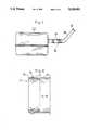
- FIG. 7is a schematic view of the entire structure of an automobile fuel tank
- FIG. 8is a vertical cross-sectional view showing a condition of the valve body attached in the metal pipe in FIG. 3;
- FIG. 9is a vertical cross-sectional view showing that the valve body will not easily come off:
- FIG. 10is a vertical cross-sectional view showing, on the contrary, that the valve body can be easily inserted into the pipe.
- a check valve apparatus 10 for a fuel tank used, for example, in an automobile, according to the present inventionis provided within an end of a pipe 23 from a fuel supply spout 21 to the fuel tank 22.
- the check valve apparatus 10is installed in such a manner that a valve body 3 extends substantially horizontally, to thereby be opened when fuel flows toward the tank 22 at the time of fuel supply and closed when fuel flows reversely.
- a valve plate 1is integral with rotating rod members 2 at a position displaced from the center line so that it maintains the closed state due to its own weight. Since the valve plate 1 in the closed state is affected by a pressure from the tank 22, mechanical strength of synthetic resin, surface ribs, an appropriate thickness and so forth are arranged to make the valve plate 1 rigid enough to stand the pressure.
- the valve body 3made of synthetic resin and having an annular shape which supports the outer periphery of the valve plate 1 is provided with bearing sections 4 at positions corresponding to the valve plate rotating rod members 2.
- Each of the bearing sections 4comprises hook-like upper and lower bearing projections 9 which are formed on the inner periphery of the valve body 3 so as to surround the associated valve plate rotating rod member 2.
- an inner peripheral rib 12is provided on the rear side with respect to the center line of the rod members 2 and below the bearing sections 4, and an inner peripheral rib 13 is provided on the front side with respect to the center line of the rod members 2 and above the bearing sections 4, to thereby permit the valve plate 1 to rotate in only one direction.
- the annular valve body 3is merely pressed against its resilience radially inwardly (toward the center) from directions indicated by upper and lower arrows in FIG. 4 to expand the diameter to enlarge the distance between the left and right bearing sections 4 so that the rotating rod members 2 projecting from both sides of the valve plate 1 can be fitted in the bearing sections 4.
- the bearing sections 4recover the original posture, and the rotating rod members 2 are fitted in them by snap action, thus completing the assembly.
- the apparatuscan be constituted only of the two members.
- Retainer projections 5are provided at three positions on the outer periphery of the valve body 3. Among these retainer projections 5, two upper ones are located at positions corresponding to the rotating rod members 2 which are formed at the position displaced from the Center line of the valve plate 1, while the remaining one is additionally provided at a lower position.
- a positioning projection 6is formed at an upper location on the outer periphery of the valve body 3. As shown in FIG. 3, the apparatus of the invention can be properly set within the pipe 23 by merely fitting the positioning projection 6 in a cutout 7 formed in the pipe 23 during the setting operation of the apparatus.
- Another section of the outer periphery of the valve body 3is formed as a flange 14 to be contacted with an end portion of the pipe 23 for the purpose of suitably positioning the apparatus and fluid-tightly connecting the peripheral portion of the valve body 3 with the end portion of the pipe 23.
- FIG. 8illustrates a condition in which the retainer projection 5 of the valve body 3 is closely fitted in the annular recess 24 of the pipe 23.
- the valve body 3In order to insert the apparatus into a joint section of the pipe 23, the valve body 3 is inclined relative to the pipe 23, as shown in FIG. 10, so that the portion p of the valve body 3 with no retainer projection 5 will be closely fitted to the end portion of the pipe 23, and that the retainer projection 5 of the valve body 3 can be easily inserted into the annular recess 24 of the pipe 23.
- the valve body 3is inclined relative to the pipe 23, as shown in FIG. 10, so that the portion P of the valve body 3 with no retainer projection 5 will be closely fitted to the end portion of the pipe 23, and that the retainer projection 5 of the valve body 3 can be easily detached from the annular recess 24 of the pipe 23.
- the retainer projections 5are provided on the outer periphery of the bearing sections 4 of the valve body 3 which sustain the rotating rod members 2 projecting from both sides of the valve plate 1, the amount of radially inward deformation of the valve body 3 is limited by the valve plate rotating rod members 2 which serve as a strut, so that the valve body 3 can be prevented from coming off from the pipe 23 during operation.
- the check valve apparatus for the fuel tank according to the present inventionis easy to assemble, and the number of component parts is lessened, thereby achieving the reduction of costs.
- the check valve apparatusis also arranged such that the valve plate will not be easily detached from the valve body, and that the valve body will not accidentally come off from the pipe.
- the check valve apparatusis improved in corrosion resistance, to thereby function favorably for a long period of time in such a manner as to be open when fuel flows normally toward the tank at the time of fuel supply and closed when fuel flows reversely.
Landscapes
- Engineering & Computer Science (AREA)
- General Engineering & Computer Science (AREA)
- Mechanical Engineering (AREA)
- Life Sciences & Earth Sciences (AREA)
- Sustainable Development (AREA)
- Sustainable Energy (AREA)
- Chemical & Material Sciences (AREA)
- Combustion & Propulsion (AREA)
- Transportation (AREA)
- Cooling, Air Intake And Gas Exhaust, And Fuel Tank Arrangements In Propulsion Units (AREA)
Abstract
Description
1. Industrial Field of the Invention
The present invention relates to a check valve apparatus for a fuel tank which is provided in a an end of pipe from a fuel supply spout to the fuel tank so that the check valve apparatus is opened when fuel flows toward the fuel tank at the time of fuel supply and closed when fuel flows reversely.
2. Description of the Prior Art
An example of conventional check valve apparatus for a fuel tank which functions in such a manner as to be open when fuel flows normally toward the tank at the time of fuel supply and closed when fuel flows reversely is disclosed in U.S. Pat. No. 4,128,111. This apparatus comprises independent component parts, such as a valve body, a valve plate, rotational axis pins, and the number of parts is large. Further, it is necessary to smash the tip of each of the rotational axis pin after the pin is assembled with the apparatus so that the pin will not dislodge.
The present invention has been accomplished to facilitate the assembling operation of such a check valve apparatus for a fuel tank and to reduce the number of its component parts. At the same time, there has been studied the structure of the check valve apparatus with which a valve plate will not be easily detached and the assembled apparatus will not accidentally come off from pipe.
A check valve apparatus for a fuel tank according to the present invention is characterized in that it comprises a valve plate made of synthetic resin, which is integral with rotating rod members at a position displaced from the circle center point of the valve plate, and a valve body made of synthetic resin including an annular valve seat which supports the outer periphery of the valve plate, the valve body including retainer projections which are provided on some portions of the outer peripheral side of the valve body, on the other side of which portions there are provided bearing sections corresponding to the rotating rod members of the valve plate.
The annular valve body in this case may be arranged in such a manner that the retainer projections are additionally formed at certain positions other than the two positions on the outer peripheral side of the valve body corresponding to those of the bearing sections. A positioning projection may be provided on the outer periphery of the valve body so as to be fitted in a cutout formed in the pipe. Projections may be further formed in the vicinity of the bearing sections in order to function as stoppers against the valve opening.
FIG. 1 is an exploded perspective view of a check valve apparatus for a fuel tank according to the present invention;
FIG. 2 is a front view of the apparatus when assembled;
FIG. 3 is a cross-sectional view of the apparatus when installed in a pipe, taken along a line I--I in FIG. 2;
FIG. 4 is a back view of the apparatus when assembled, with a valve plate being open;
FIG. 5 is a front view of a valve body when the valve plate is removed;
FIG. 6 is a cross-sectional view of the valve body, taken along a line II--II in FIG. 5;
FIG. 7 is a schematic view of the entire structure of an automobile fuel tank;
FIG. 8 is a vertical cross-sectional view showing a condition of the valve body attached in the metal pipe in FIG. 3;
FIG. 9 is a vertical cross-sectional view showing that the valve body will not easily come off: and
FIG. 10 is a vertical cross-sectional view showing, on the contrary, that the valve body can be easily inserted into the pipe.
As shown in FIG. 7, acheck valve apparatus 10 for a fuel tank used, for example, in an automobile, according to the present invention is provided within an end of apipe 23 from afuel supply spout 21 to thefuel tank 22. Thecheck valve apparatus 10 is installed in such a manner that avalve body 3 extends substantially horizontally, to thereby be opened when fuel flows toward thetank 22 at the time of fuel supply and closed when fuel flows reversely. Referring to the right side of FIG. 1, avalve plate 1 is integral with rotatingrod members 2 at a position displaced from the center line so that it maintains the closed state due to its own weight. Since thevalve plate 1 in the closed state is affected by a pressure from thetank 22, mechanical strength of synthetic resin, surface ribs, an appropriate thickness and so forth are arranged to make thevalve plate 1 rigid enough to stand the pressure.
Referring to the left side of FIG. 1, thevalve body 3 made of synthetic resin and having an annular shape which supports the outer periphery of thevalve plate 1 is provided withbearing sections 4 at positions corresponding to the valve plate rotatingrod members 2. Each of thebearing sections 4 comprises hook-like upper andlower bearing projections 9 which are formed on the inner periphery of thevalve body 3 so as to surround the associated valve plate rotatingrod member 2. Also, on the inner periphery of thevalve body 3, an innerperipheral rib 12 is provided on the rear side with respect to the center line of therod members 2 and below thebearing sections 4, and an innerperipheral rib 13 is provided on the front side with respect to the center line of therod members 2 and above thebearing sections 4, to thereby permit thevalve plate 1 to rotate in only one direction. These innerperipheral ribs valve plate 1 which has been opened and extended horizontally,stopper projections 8 are formed in the vicinity of thebearing sections 4 and on the rear side with respect to the center line of therod members 2. When referring to FIGS. 2 to 6, structures of these component parts will be understood more clearly.
In order to assemble thevalve plate 1 with thevalve body 3 in the check valve apparatus for the fuel tank according to the present invention, theannular valve body 3 is merely pressed against its resilience radially inwardly (toward the center) from directions indicated by upper and lower arrows in FIG. 4 to expand the diameter to enlarge the distance between the left and right bearingsections 4 so that the rotatingrod members 2 projecting from both sides of thevalve plate 1 can be fitted in thebearing sections 4. When pressing thevalve body 3 is stopped, thebearing sections 4 recover the original posture, and the rotatingrod members 2 are fitted in them by snap action, thus completing the assembly. In this manner, the apparatus can be constituted only of the two members.
When each of theupper retainer projections 5 is located at a position corresponding to the rotatingrod member 2 of thevalve plate 1 and formed on a portion of the outer peripheral side of thevalve body 3 on the other side of which thebearing section 4 on an extension of the rotatingrod member 2 is provided, the assembly is completed by merely pressing theretainer projections 5 into anannular recess 24 of themetal pipe 23.
FIG. 8 illustrates a condition in which theretainer projection 5 of thevalve body 3 is closely fitted in theannular recess 24 of thepipe 23. When an external force F in a direction for withdrawing thevalve body 3 is exerted on thevalve body 3 in this condition due to a force of fluid flowing within thepipe 23, as shown in FIG. 9, a portion P of thevalve body 3 with noretainer projection 5 or with no resistance is moved first. Consequently, thevalve body 3 is inclined relative to thepipe 23, and strong engagement between a portion Q of thevalve body 3 with theretainer projection 5 and thepipe 23 continues to be maintained. When the apparatus is inserted into thepipe 23, the length of the overlapped connection becomes as short as possible to facilitate the inserting operation. In order to insert the apparatus into a joint section of thepipe 23, thevalve body 3 is inclined relative to thepipe 23, as shown in FIG. 10, so that the portion p of thevalve body 3 with noretainer projection 5 will be closely fitted to the end portion of thepipe 23, and that theretainer projection 5 of thevalve body 3 can be easily inserted into theannular recess 24 of thepipe 23. Similarly, when the apparatus is detached from the joint section of thepipe 23, thevalve body 3 is inclined relative to thepipe 23, as shown in FIG. 10, so that the portion P of thevalve body 3 with noretainer projection 5 will be closely fitted to the end portion of thepipe 23, and that theretainer projection 5 of thevalve body 3 can be easily detached from theannular recess 24 of thepipe 23.
Moreover, since theretainer projections 5 are provided on the outer periphery of thebearing sections 4 of thevalve body 3 which sustain the rotatingrod members 2 projecting from both sides of thevalve plate 1, the amount of radially inward deformation of thevalve body 3 is limited by the valve plate rotatingrod members 2 which serve as a strut, so that thevalve body 3 can be prevented from coming off from thepipe 23 during operation.
As described heretofore, the check valve apparatus for the fuel tank according to the present invention is easy to assemble, and the number of component parts is lessened, thereby achieving the reduction of costs. The check valve apparatus is also arranged such that the valve plate will not be easily detached from the valve body, and that the valve body will not accidentally come off from the pipe. Besides, the check valve apparatus is improved in corrosion resistance, to thereby function favorably for a long period of time in such a manner as to be open when fuel flows normally toward the tank at the time of fuel supply and closed when fuel flows reversely.
Claims (6)
1. A check valve apparatus, which is provided in an end of a pipe from a fuel supply spout to a fuel tank so that said check valve apparatus is opened when fuel flows toward said fuel tank at a time of fuel supply and is closed when fuel flows reversely, comprising:
a valve plate made of synthetic resin, which is formed with rotating rod members as one body at a position displaced from the circle center point of the valve plate; and
a valve body made of synthetic resin and having an annular shape which supports outer periphery of said valve plate, said valve body including retainer projections
said retainer projections are provided on two portions of the outer peripheral side of said valve body, and on the other side of which portions there are formed bearing sections corresponding to said rotating rod members of the valve plate.
2. A check valve apparatus for a fuel tank according to claim 1, wherein at least said retainer projections are closely fitted in an annular recess formed in the inner surface of a pipe which is arranged to engage with said annular valve body.
3. A check valve apparatus installed between a fuel supply spout and a fuel tank so as to be opened when fuel flows toward said fuel tank and closed when fuel flows back, said valve apparatus comprising:
a valve plate made of synthetic resin formed with rotating rod members as one body at a position displaced from a circle center point of said valve plate; and
a valve body made of synthetic resin having an annular shape and supporting an outer periphery of said valve plate, said valve body including retainer projections provided on two portions of an outer periphery of said valve body and bearing section on an inner periphery so as to correspond to said rotating rod members of said valve plate.
4. A check valve apparatus, which is installed in a pipe connecting a fuel inlet to a fuel tank and is opened when fuel flows into said fuel tank and closed when fuel flows back comprising:
a valve plate made of synthetic resin having rotating rod members near one end;
an annular shape valve body made of synthetic resin which supports outer periphery of said valve plate, said valve body being provided with:
two retainer projections provided on the outer periphery and two bearing sections on the inner periphery so that said rotating rod members of the valve plate are fitted therein, said retainer projections being connected to an annular recess formed inside of said pipe;
two inner peripheral ribs, one of said two ribs being on a rear side with respect to a center line of said rod members and below said bearing sections and another one of said two ribs being provided on a front side with respect to a center line of said rod members and above said bearing sections;
stopper projections formed in the vicinity of said bearing sections and on a rear side with respect to a center line of said rod members;
a positioning projection formed at an upper location on said outer periphery of said valve body;
hook-like upper and lower bearing projections formed on said inner periphery of said valve body; and
a flange provided on said outer periphery of said valve body for positioning said check valve apparatus and fluid-tightly connecting a peripheral portion of said valve body to an end of said pipe.
5. A check valve apparatus according to claim 3, wherein said retainer projection are closely fitted in an annular recess formed in an inner surface of said pipe which engages with said annular valve body.
6. A check valve apparatus according to claim 4, wherein said retainer projection are closely fitted in an annular recess formed in an inner surface of said pipe which engages with said annular valve body.
Priority Applications (1)
| Application Number | Priority Date | Filing Date | Title |
|---|---|---|---|
| US07/758,891US5159953A (en) | 1991-09-11 | 1991-09-11 | Check valve apparatus for fuel tank |
Applications Claiming Priority (1)
| Application Number | Priority Date | Filing Date | Title |
|---|---|---|---|
| US07/758,891US5159953A (en) | 1991-09-11 | 1991-09-11 | Check valve apparatus for fuel tank |
Publications (1)
| Publication Number | Publication Date |
|---|---|
| US5159953Atrue US5159953A (en) | 1992-11-03 |
Family
ID=25053514
Family Applications (1)
| Application Number | Title | Priority Date | Filing Date |
|---|---|---|---|
| US07/758,891Expired - LifetimeUS5159953A (en) | 1991-09-11 | 1991-09-11 | Check valve apparatus for fuel tank |
Country Status (1)
| Country | Link |
|---|---|
| US (1) | US5159953A (en) |
Cited By (25)
| Publication number | Priority date | Publication date | Assignee | Title |
|---|---|---|---|---|
| FR2740739A1 (en)* | 1995-11-08 | 1997-05-09 | Journee Paul Sa | IMPROVED DEVICE FOR FILLING A MOTOR VEHICLE FUEL TANK |
| FR2761974A1 (en)* | 1997-04-09 | 1998-10-16 | Journee Paul Sa | Anti-return valve for motor vehicle fuel pipe |
| US5881757A (en)* | 1997-05-02 | 1999-03-16 | Senninger Irrigation, Inc. | Pressure regulator apparatus and method |
| EP0864456A3 (en)* | 1997-03-11 | 1999-08-18 | Borg-Warner Automotive, Inc. | Fuel tank filler neck check valve preventing fuel leakage |
| KR100286274B1 (en)* | 1997-08-27 | 2001-06-01 | 가부시키가이샤 니프코 | Non-return valve |
| US6305413B1 (en) | 1999-02-19 | 2001-10-23 | Ultradent Products, Inc. | Mixing adaptor system |
| US20040025944A1 (en)* | 2002-08-07 | 2004-02-12 | Kane Whitaker | Back flow prevention device for pipelines conveying fluids |
| US20040084094A1 (en)* | 2002-11-01 | 2004-05-06 | Asteer Co., Ltd. | Fuel feeding pipe |
| EP1479554A1 (en)* | 2003-05-23 | 2004-11-24 | Eaton Corporation | Flapper type fill tube check valve |
| US20050139271A1 (en)* | 2001-12-21 | 2005-06-30 | Krishnamoorthy Pk H. | Assembling a siphonable filler tube with a check valve on a fuel tank |
| WO2006051117A1 (en)* | 2004-11-15 | 2006-05-18 | Inergy Automotive Systems Research (Société Anonyme) | Plastic adapter for fuel tank |
| US20090000666A1 (en)* | 2007-06-21 | 2009-01-01 | Peyton Nicholaus J | Anchor Valve for Security |
| US20090120005A1 (en)* | 2007-11-13 | 2009-05-14 | Edgar Grant Eckenswiller | Drain |
| KR100912349B1 (en)* | 2001-12-21 | 2009-08-14 | 이턴 코포레이션 | One-way valve assembly |
| US20120192950A1 (en)* | 2011-01-31 | 2012-08-02 | Kevin Dean Huber | Floor drain valve with resiliently mounted rigid flappers |
| WO2014009640A1 (en)* | 2012-07-10 | 2014-01-16 | Turbomeca | Filling device for fluid tank |
| US20140053923A1 (en)* | 2012-08-27 | 2014-02-27 | The Rectorseal Corporation | Apparatus and Methods for Limiting or Preventing Backflow of Gas up Through a Plumbing Fixture |
| US9010363B2 (en) | 2013-06-24 | 2015-04-21 | The Rectorseal Corporation | Drain valve |
| US20160025233A1 (en)* | 2008-01-21 | 2016-01-28 | Ausco, Inc. | Pressure relief valve with singular body |
| US9416986B2 (en) | 2013-06-24 | 2016-08-16 | The Rectorseal Corporation | Valve for roof vent |
| US9506575B2 (en) | 2014-07-09 | 2016-11-29 | Mueller International, Llc | Check valve disc |
| US9752692B2 (en) | 2016-01-13 | 2017-09-05 | Mueller International, Llc | Check valve with accelerated closure |
| US10648581B2 (en)* | 2017-12-15 | 2020-05-12 | Hamilton Sundstrand Corporation | Check valves |
| US10914399B1 (en)* | 2019-07-31 | 2021-02-09 | Jeremy Hohnbaum | System and apparatus for controlling fluid flow in drainage systems |
| CN115427714A (en)* | 2020-04-24 | 2022-12-02 | 航天喷气发动机洛克达因股份有限公司 | Valve unit with ball lock |
Citations (12)
| Publication number | Priority date | Publication date | Assignee | Title |
|---|---|---|---|---|
| US202219A (en)* | 1878-04-09 | Improvement in gas and water valves for sewerage-connections | ||
| US1107096A (en)* | 1913-10-29 | 1914-08-11 | Martin Mulloy Sr | Catch-basin for sewers. |
| US1399004A (en)* | 1919-08-19 | 1921-12-06 | Edward R Case | Automatic air-valve |
| US2664264A (en)* | 1949-10-11 | 1953-12-29 | Crane Co | Check valve mounting |
| US2711188A (en)* | 1951-05-10 | 1955-06-21 | Chapman Valve Mfg Co | Check valve |
| US2787206A (en)* | 1954-04-09 | 1957-04-02 | Ford Motor Co | Vehicle air conditioning intake duct |
| US3395727A (en)* | 1965-03-01 | 1968-08-06 | Anderson Greenwood & Co | Check valve |
| US3448465A (en)* | 1966-07-11 | 1969-06-10 | Us Health Education & Welfare | Pivoted butterfly type heart valve |
| US4128111A (en)* | 1976-06-18 | 1978-12-05 | Hansen George E | Wafer swing check valves |
| US4295412A (en)* | 1978-12-19 | 1981-10-20 | Nissin Kogyo Kabushiki Kaisha | Hose with a one-way valve for a vacuum operated servomotor |
| US4492249A (en)* | 1981-06-03 | 1985-01-08 | Jidosha Kiki Co., Ltd. | Mounted check valve assembly |
| US4850059A (en)* | 1988-05-17 | 1989-07-25 | Jim Dickerson Plumbing, Inc. | Apparatus for preventing backing up of sewage in a building |
- 1991
- 1991-09-11USUS07/758,891patent/US5159953A/ennot_activeExpired - Lifetime
Patent Citations (12)
| Publication number | Priority date | Publication date | Assignee | Title |
|---|---|---|---|---|
| US202219A (en)* | 1878-04-09 | Improvement in gas and water valves for sewerage-connections | ||
| US1107096A (en)* | 1913-10-29 | 1914-08-11 | Martin Mulloy Sr | Catch-basin for sewers. |
| US1399004A (en)* | 1919-08-19 | 1921-12-06 | Edward R Case | Automatic air-valve |
| US2664264A (en)* | 1949-10-11 | 1953-12-29 | Crane Co | Check valve mounting |
| US2711188A (en)* | 1951-05-10 | 1955-06-21 | Chapman Valve Mfg Co | Check valve |
| US2787206A (en)* | 1954-04-09 | 1957-04-02 | Ford Motor Co | Vehicle air conditioning intake duct |
| US3395727A (en)* | 1965-03-01 | 1968-08-06 | Anderson Greenwood & Co | Check valve |
| US3448465A (en)* | 1966-07-11 | 1969-06-10 | Us Health Education & Welfare | Pivoted butterfly type heart valve |
| US4128111A (en)* | 1976-06-18 | 1978-12-05 | Hansen George E | Wafer swing check valves |
| US4295412A (en)* | 1978-12-19 | 1981-10-20 | Nissin Kogyo Kabushiki Kaisha | Hose with a one-way valve for a vacuum operated servomotor |
| US4492249A (en)* | 1981-06-03 | 1985-01-08 | Jidosha Kiki Co., Ltd. | Mounted check valve assembly |
| US4850059A (en)* | 1988-05-17 | 1989-07-25 | Jim Dickerson Plumbing, Inc. | Apparatus for preventing backing up of sewage in a building |
Cited By (47)
| Publication number | Priority date | Publication date | Assignee | Title |
|---|---|---|---|---|
| FR2740739A1 (en)* | 1995-11-08 | 1997-05-09 | Journee Paul Sa | IMPROVED DEVICE FOR FILLING A MOTOR VEHICLE FUEL TANK |
| EP0774373A2 (en) | 1995-11-08 | 1997-05-21 | Paul Journee S.A. | Arrangement for filling a motor vehicle fuel tank |
| EP0774373A3 (en)* | 1995-11-08 | 1997-07-09 | Journee Paul Sa | Arrangement for filling a motor vehicle fuel tank |
| EP0864456A3 (en)* | 1997-03-11 | 1999-08-18 | Borg-Warner Automotive, Inc. | Fuel tank filler neck check valve preventing fuel leakage |
| FR2761974A1 (en)* | 1997-04-09 | 1998-10-16 | Journee Paul Sa | Anti-return valve for motor vehicle fuel pipe |
| US5881757A (en)* | 1997-05-02 | 1999-03-16 | Senninger Irrigation, Inc. | Pressure regulator apparatus and method |
| KR100286274B1 (en)* | 1997-08-27 | 2001-06-01 | 가부시키가이샤 니프코 | Non-return valve |
| US6305413B1 (en) | 1999-02-19 | 2001-10-23 | Ultradent Products, Inc. | Mixing adaptor system |
| AU761376B2 (en)* | 1999-02-19 | 2003-06-05 | Ultradent Products, Inc. | Mixing adaptor and system |
| US7458391B2 (en)* | 2001-12-21 | 2008-12-02 | Eaton Corporation | Assembling a siphonable filler tube with a check valve on a fuel tank |
| KR100912349B1 (en)* | 2001-12-21 | 2009-08-14 | 이턴 코포레이션 | One-way valve assembly |
| US20050139271A1 (en)* | 2001-12-21 | 2005-06-30 | Krishnamoorthy Pk H. | Assembling a siphonable filler tube with a check valve on a fuel tank |
| US20040025944A1 (en)* | 2002-08-07 | 2004-02-12 | Kane Whitaker | Back flow prevention device for pipelines conveying fluids |
| US6929023B2 (en)* | 2002-08-07 | 2005-08-16 | Polycheck Corporation | Back flow prevention device for pipelines conveying fluids |
| US20040084094A1 (en)* | 2002-11-01 | 2004-05-06 | Asteer Co., Ltd. | Fuel feeding pipe |
| US7040669B2 (en)* | 2002-11-01 | 2006-05-09 | Asteer Co., Ltd. | Fuel feeding pipe |
| US20050279405A1 (en)* | 2003-05-23 | 2005-12-22 | Eaton Corporation | Flapper type fill tube check valve |
| US6932100B2 (en) | 2003-05-23 | 2005-08-23 | Eaton Corporation | Flapper type fill tube check valve |
| EP1479554A1 (en)* | 2003-05-23 | 2004-11-24 | Eaton Corporation | Flapper type fill tube check valve |
| US7458385B2 (en) | 2003-05-23 | 2008-12-02 | Eaton Corporation | Flapper type fill tube check valve |
| US20090078336A1 (en)* | 2004-11-15 | 2009-03-26 | Inergy Auto. Systems Research (Societe Anonyme) | Plastic adapter for fuel tank |
| CN101056778B (en)* | 2004-11-15 | 2010-05-05 | 因勒纪汽车系统研究公司 | Plastic connector for fuel tank |
| FR2877883A1 (en)* | 2004-11-15 | 2006-05-19 | Inergy Automotive Systems Res | PLASTIC BIT FOR FUEL TANK |
| US7857016B2 (en) | 2004-11-15 | 2010-12-28 | Inergy Automotive Systems Research (Société Anonyme | Plastic adapter for fuel tank |
| WO2006051117A1 (en)* | 2004-11-15 | 2006-05-18 | Inergy Automotive Systems Research (Société Anonyme) | Plastic adapter for fuel tank |
| US9534359B2 (en) | 2007-06-21 | 2017-01-03 | Mueller International, Llc | Anchor valve for security |
| US8733381B2 (en)* | 2007-06-21 | 2014-05-27 | Mueller International, Llc | Anchor valve for security |
| US20090000666A1 (en)* | 2007-06-21 | 2009-01-01 | Peyton Nicholaus J | Anchor Valve for Security |
| US20090120005A1 (en)* | 2007-11-13 | 2009-05-14 | Edgar Grant Eckenswiller | Drain |
| US7730679B2 (en)* | 2007-11-13 | 2010-06-08 | Edgar Grant Eckenswiller | Drain for a door or window sash or frame |
| US9371926B2 (en)* | 2008-01-21 | 2016-06-21 | Ausco, Inc. | Pressure relief valve with singular body |
| US20160025233A1 (en)* | 2008-01-21 | 2016-01-28 | Ausco, Inc. | Pressure relief valve with singular body |
| US20120192950A1 (en)* | 2011-01-31 | 2012-08-02 | Kevin Dean Huber | Floor drain valve with resiliently mounted rigid flappers |
| US9139991B2 (en)* | 2011-01-31 | 2015-09-22 | The Rectorseal Corporation | Floor drain valve with resiliently mounted rigid flappers |
| US9561949B2 (en) | 2012-07-10 | 2017-02-07 | Turbomeca | Filler device for a fluid tank |
| CN104520193A (en)* | 2012-07-10 | 2015-04-15 | 涡轮梅坎公司 | Filling device for fluid tank |
| WO2014009640A1 (en)* | 2012-07-10 | 2014-01-16 | Turbomeca | Filling device for fluid tank |
| US20140053923A1 (en)* | 2012-08-27 | 2014-02-27 | The Rectorseal Corporation | Apparatus and Methods for Limiting or Preventing Backflow of Gas up Through a Plumbing Fixture |
| US9010363B2 (en) | 2013-06-24 | 2015-04-21 | The Rectorseal Corporation | Drain valve |
| US9416986B2 (en) | 2013-06-24 | 2016-08-16 | The Rectorseal Corporation | Valve for roof vent |
| US9506575B2 (en) | 2014-07-09 | 2016-11-29 | Mueller International, Llc | Check valve disc |
| US9945487B2 (en) | 2016-01-13 | 2018-04-17 | Mueller International, Llc | Check valve with accelerated closure |
| US9752692B2 (en) | 2016-01-13 | 2017-09-05 | Mueller International, Llc | Check valve with accelerated closure |
| US10648581B2 (en)* | 2017-12-15 | 2020-05-12 | Hamilton Sundstrand Corporation | Check valves |
| US10914399B1 (en)* | 2019-07-31 | 2021-02-09 | Jeremy Hohnbaum | System and apparatus for controlling fluid flow in drainage systems |
| US11473696B1 (en) | 2019-07-31 | 2022-10-18 | Jeremy Hohnbaum | System and apparatus for controlling fluid flow in drainage systems with a cage device |
| CN115427714A (en)* | 2020-04-24 | 2022-12-02 | 航天喷气发动机洛克达因股份有限公司 | Valve unit with ball lock |
Similar Documents
| Publication | Publication Date | Title |
|---|---|---|
| US5159953A (en) | Check valve apparatus for fuel tank | |
| US5193579A (en) | Internal combustion engine lubricating oil filter valve | |
| US5092703A (en) | Ball joint and method of manufacturing the same | |
| US5833203A (en) | System for fitting a part of a seat to a motor vehicle | |
| US4579141A (en) | Filling and discharging valve for inflatable hollow bodies | |
| DE69202966T2 (en) | Safety valve. | |
| US5080269A (en) | Fixation device | |
| US7481595B2 (en) | Ball joint | |
| US5626433A (en) | Ball joint | |
| IE52581B1 (en) | Improvements in and relating to pivot joints | |
| US6026853A (en) | Fuel tank filler neck check valve | |
| JP3639213B2 (en) | One way flow valve quick connector for fuel tank | |
| JP5455256B2 (en) | Pipe fittings and wall members for conduits in the region of wall through-holes | |
| DE4011854C2 (en) | ||
| JPS5851485B2 (en) | Construction of a new type of tank for automobiles | |
| US3244195A (en) | Capsule-type check valve | |
| US4113300A (en) | Filler connection for vehicles driven by internal combustion engines | |
| US5222519A (en) | Reverse-flow prevention device for fuel tank | |
| CA1132524A (en) | Means to retain a valve stem | |
| EP1697157B1 (en) | Bleed valve | |
| US4878909A (en) | High efficiency cardiac valve | |
| JPH0354031Y2 (en) | ||
| KR100286274B1 (en) | Non-return valve | |
| US4016900A (en) | Springless valve for pneumatic tires and the like | |
| DE69207132T2 (en) | Hydropneumatic unit with a diaphragm accumulator and an asymmetrical damper |
Legal Events
| Date | Code | Title | Description |
|---|---|---|---|
| AS | Assignment | Owner name:OM INDUSTRIAL CO., LTD., JAPAN Free format text:ASSIGNMENT OF ASSIGNORS INTEREST.;ASSIGNORS:SATO, KYOKUICHI;FUJITA, JUICHI;REEL/FRAME:005849/0618 Effective date:19910807 | |
| STCF | Information on status: patent grant | Free format text:PATENTED CASE | |
| FPAY | Fee payment | Year of fee payment:4 | |
| FEPP | Fee payment procedure | Free format text:PAYOR NUMBER ASSIGNED (ORIGINAL EVENT CODE: ASPN); ENTITY STATUS OF PATENT OWNER: LARGE ENTITY | |
| FPAY | Fee payment | Year of fee payment:8 | |
| FEPP | Fee payment procedure | Free format text:PAYER NUMBER DE-ASSIGNED (ORIGINAL EVENT CODE: RMPN); ENTITY STATUS OF PATENT OWNER: LARGE ENTITY Free format text:PAYOR NUMBER ASSIGNED (ORIGINAL EVENT CODE: ASPN); ENTITY STATUS OF PATENT OWNER: LARGE ENTITY | |
| AS | Assignment | Owner name:ASTEER CO., LTD., JAPAN Free format text:MERGER;ASSIGNOR:OM CORPORATION;REEL/FRAME:014770/0989 Effective date:20031001 | |
| FPAY | Fee payment | Year of fee payment:12 |