US5159931A - Apparatus for obtaining a three-dimensional reconstruction of anatomic structures through the acquisition of echographic images - Google Patents
Apparatus for obtaining a three-dimensional reconstruction of anatomic structures through the acquisition of echographic imagesDownload PDFInfo
- Publication number
- US5159931A US5159931AUS07/438,292US43829289AUS5159931AUS 5159931 AUS5159931 AUS 5159931AUS 43829289 AUS43829289 AUS 43829289AUS 5159931 AUS5159931 AUS 5159931A
- Authority
- US
- United States
- Prior art keywords
- dimensional
- probe
- transducer
- echographic
- scanning
- Prior art date
- Legal status (The legal status is an assumption and is not a legal conclusion. Google has not performed a legal analysis and makes no representation as to the accuracy of the status listed.)
- Expired - Lifetime
Links
- 239000000523sampleSubstances0.000claimsabstractdescription81
- 238000002604ultrasonographyMethods0.000claimsabstractdescription40
- 238000012545processingMethods0.000claimsabstractdescription18
- 239000013598vectorSubstances0.000claimsabstractdescription18
- 239000011159matrix materialSubstances0.000claimsabstractdescription16
- 230000033001locomotionEffects0.000claimsabstractdescription15
- 230000000747cardiac effectEffects0.000claimsdescription30
- 230000015654memoryEffects0.000claimsdescription11
- 238000003491arrayMethods0.000claimsdescription6
- 230000005540biological transmissionEffects0.000claimsdescription5
- 230000001934delayEffects0.000claimsdescription5
- 210000003484anatomyAnatomy0.000claimsdescription4
- 238000006073displacement reactionMethods0.000claimsdescription4
- 238000013507mappingMethods0.000claimsdescription3
- 239000003086colorantSubstances0.000claimsdescription2
- 238000010276constructionMethods0.000claimsdescription2
- 230000009466transformationEffects0.000claimsdescription2
- 239000008280bloodSubstances0.000claims1
- 210000004369bloodAnatomy0.000claims1
- 238000001514detection methodMethods0.000claims1
- 238000011835investigationMethods0.000claims1
- 238000001454recorded imageMethods0.000claims1
- 238000000034methodMethods0.000description30
- 230000008569processEffects0.000description18
- 230000006870functionEffects0.000description13
- 230000033764rhythmic processEffects0.000description8
- 238000010586diagramMethods0.000description7
- 230000017531blood circulationEffects0.000description6
- 239000000919ceramicSubstances0.000description6
- 210000000056organAnatomy0.000description6
- 206010003658Atrial FibrillationDiseases0.000description5
- 206010003119arrhythmiaDiseases0.000description5
- 230000006793arrhythmiaEffects0.000description5
- 230000001788irregularEffects0.000description5
- 238000003325tomographyMethods0.000description4
- 238000010304firingMethods0.000description3
- 230000003287optical effectEffects0.000description3
- 230000001575pathological effectEffects0.000description3
- 238000012800visualizationMethods0.000description3
- 239000002131composite materialSubstances0.000description2
- 230000000994depressogenic effectEffects0.000description2
- 230000004807localizationEffects0.000description2
- 238000005259measurementMethods0.000description2
- 230000001360synchronised effectEffects0.000description2
- 238000005481NMR spectroscopyMethods0.000description1
- 206010028980NeoplasmDiseases0.000description1
- 208000000418Premature Cardiac ComplexesDiseases0.000description1
- 230000002763arrhythmic effectEffects0.000description1
- 230000002457bidirectional effectEffects0.000description1
- 230000015572biosynthetic processEffects0.000description1
- 210000004204blood vesselAnatomy0.000description1
- 210000000481breastAnatomy0.000description1
- 210000000038chestAnatomy0.000description1
- 230000008878couplingEffects0.000description1
- 238000010168coupling processMethods0.000description1
- 238000005859coupling reactionMethods0.000description1
- 230000001066destructive effectEffects0.000description1
- 238000002405diagnostic procedureMethods0.000description1
- 230000000694effectsEffects0.000description1
- 230000002708enhancing effectEffects0.000description1
- 238000011156evaluationMethods0.000description1
- 238000005755formation reactionMethods0.000description1
- 238000003780insertionMethods0.000description1
- 230000037431insertionEffects0.000description1
- 238000002372labellingMethods0.000description1
- 210000005240left ventricleAnatomy0.000description1
- 210000004072lungAnatomy0.000description1
- 239000000463materialSubstances0.000description1
- 238000012986modificationMethods0.000description1
- 230000004048modificationEffects0.000description1
- 230000003534oscillatory effectEffects0.000description1
- 230000001020rhythmical effectEffects0.000description1
- 238000012360testing methodMethods0.000description1
- 230000007704transitionEffects0.000description1
- XLYOFNOQVPJJNP-UHFFFAOYSA-NwaterSubstancesOXLYOFNOQVPJJNP-UHFFFAOYSA-N0.000description1
Images


Classifications
- G—PHYSICS
- G10—MUSICAL INSTRUMENTS; ACOUSTICS
- G10K—SOUND-PRODUCING DEVICES; METHODS OR DEVICES FOR PROTECTING AGAINST, OR FOR DAMPING, NOISE OR OTHER ACOUSTIC WAVES IN GENERAL; ACOUSTICS NOT OTHERWISE PROVIDED FOR
- G10K11/00—Methods or devices for transmitting, conducting or directing sound in general; Methods or devices for protecting against, or for damping, noise or other acoustic waves in general
- G10K11/18—Methods or devices for transmitting, conducting or directing sound
- G10K11/26—Sound-focusing or directing, e.g. scanning
- G10K11/35—Sound-focusing or directing, e.g. scanning using mechanical steering of transducers or their beams
- G10K11/352—Sound-focusing or directing, e.g. scanning using mechanical steering of transducers or their beams by moving the transducer
- A—HUMAN NECESSITIES
- A61—MEDICAL OR VETERINARY SCIENCE; HYGIENE
- A61B—DIAGNOSIS; SURGERY; IDENTIFICATION
- A61B5/00—Measuring for diagnostic purposes; Identification of persons
- A61B5/24—Detecting, measuring or recording bioelectric or biomagnetic signals of the body or parts thereof
- A61B5/316—Modalities, i.e. specific diagnostic methods
- A61B5/318—Heart-related electrical modalities, e.g. electrocardiography [ECG]
- A61B5/346—Analysis of electrocardiograms
- A61B5/349—Detecting specific parameters of the electrocardiograph cycle
- A61B5/352—Detecting R peaks, e.g. for synchronising diagnostic apparatus; Estimating R-R interval
- A—HUMAN NECESSITIES
- A61—MEDICAL OR VETERINARY SCIENCE; HYGIENE
- A61B—DIAGNOSIS; SURGERY; IDENTIFICATION
- A61B8/00—Diagnosis using ultrasonic, sonic or infrasonic waves
- A61B8/13—Tomography
- A61B8/14—Echo-tomography
- A—HUMAN NECESSITIES
- A61—MEDICAL OR VETERINARY SCIENCE; HYGIENE
- A61B—DIAGNOSIS; SURGERY; IDENTIFICATION
- A61B8/00—Diagnosis using ultrasonic, sonic or infrasonic waves
- A61B8/48—Diagnostic techniques
- A61B8/483—Diagnostic techniques involving the acquisition of a 3D volume of data
- G—PHYSICS
- G01—MEASURING; TESTING
- G01S—RADIO DIRECTION-FINDING; RADIO NAVIGATION; DETERMINING DISTANCE OR VELOCITY BY USE OF RADIO WAVES; LOCATING OR PRESENCE-DETECTING BY USE OF THE REFLECTION OR RERADIATION OF RADIO WAVES; ANALOGOUS ARRANGEMENTS USING OTHER WAVES
- G01S15/00—Systems using the reflection or reradiation of acoustic waves, e.g. sonar systems
- G01S15/88—Sonar systems specially adapted for specific applications
- G01S15/89—Sonar systems specially adapted for specific applications for mapping or imaging
- G01S15/8906—Short-range imaging systems; Acoustic microscope systems using pulse-echo techniques
- G01S15/8909—Short-range imaging systems; Acoustic microscope systems using pulse-echo techniques using a static transducer configuration
- G01S15/8915—Short-range imaging systems; Acoustic microscope systems using pulse-echo techniques using a static transducer configuration using a transducer array
- G01S15/8925—Short-range imaging systems; Acoustic microscope systems using pulse-echo techniques using a static transducer configuration using a transducer array the array being a two-dimensional transducer configuration, i.e. matrix or orthogonal linear arrays
- G—PHYSICS
- G01—MEASURING; TESTING
- G01S—RADIO DIRECTION-FINDING; RADIO NAVIGATION; DETERMINING DISTANCE OR VELOCITY BY USE OF RADIO WAVES; LOCATING OR PRESENCE-DETECTING BY USE OF THE REFLECTION OR RERADIATION OF RADIO WAVES; ANALOGOUS ARRANGEMENTS USING OTHER WAVES
- G01S15/00—Systems using the reflection or reradiation of acoustic waves, e.g. sonar systems
- G01S15/88—Sonar systems specially adapted for specific applications
- G01S15/89—Sonar systems specially adapted for specific applications for mapping or imaging
- G01S15/8906—Short-range imaging systems; Acoustic microscope systems using pulse-echo techniques
- G01S15/8934—Short-range imaging systems; Acoustic microscope systems using pulse-echo techniques using a dynamic transducer configuration
- G01S15/8938—Short-range imaging systems; Acoustic microscope systems using pulse-echo techniques using a dynamic transducer configuration using transducers mounted for mechanical movement in two dimensions
- G01S15/894—Short-range imaging systems; Acoustic microscope systems using pulse-echo techniques using a dynamic transducer configuration using transducers mounted for mechanical movement in two dimensions by rotation about a single axis
- G—PHYSICS
- G01—MEASURING; TESTING
- G01S—RADIO DIRECTION-FINDING; RADIO NAVIGATION; DETERMINING DISTANCE OR VELOCITY BY USE OF RADIO WAVES; LOCATING OR PRESENCE-DETECTING BY USE OF THE REFLECTION OR RERADIATION OF RADIO WAVES; ANALOGOUS ARRANGEMENTS USING OTHER WAVES
- G01S15/00—Systems using the reflection or reradiation of acoustic waves, e.g. sonar systems
- G01S15/88—Sonar systems specially adapted for specific applications
- G01S15/89—Sonar systems specially adapted for specific applications for mapping or imaging
- G01S15/8906—Short-range imaging systems; Acoustic microscope systems using pulse-echo techniques
- G01S15/8993—Three dimensional imaging systems
- G—PHYSICS
- G01—MEASURING; TESTING
- G01S—RADIO DIRECTION-FINDING; RADIO NAVIGATION; DETERMINING DISTANCE OR VELOCITY BY USE OF RADIO WAVES; LOCATING OR PRESENCE-DETECTING BY USE OF THE REFLECTION OR RERADIATION OF RADIO WAVES; ANALOGOUS ARRANGEMENTS USING OTHER WAVES
- G01S7/00—Details of systems according to groups G01S13/00, G01S15/00, G01S17/00
- G01S7/52—Details of systems according to groups G01S13/00, G01S15/00, G01S17/00 of systems according to group G01S15/00
- G01S7/52017—Details of systems according to groups G01S13/00, G01S15/00, G01S17/00 of systems according to group G01S15/00 particularly adapted to short-range imaging
- G01S7/52085—Details related to the ultrasound signal acquisition, e.g. scan sequences
- G01S7/52087—Details related to the ultrasound signal acquisition, e.g. scan sequences using synchronization techniques
- A—HUMAN NECESSITIES
- A61—MEDICAL OR VETERINARY SCIENCE; HYGIENE
- A61B—DIAGNOSIS; SURGERY; IDENTIFICATION
- A61B8/00—Diagnosis using ultrasonic, sonic or infrasonic waves
- A61B8/44—Constructional features of the ultrasonic, sonic or infrasonic diagnostic device
- A61B8/4444—Constructional features of the ultrasonic, sonic or infrasonic diagnostic device related to the probe
- A61B8/4461—Features of the scanning mechanism, e.g. for moving the transducer within the housing of the probe
- A—HUMAN NECESSITIES
- A61—MEDICAL OR VETERINARY SCIENCE; HYGIENE
- A61B—DIAGNOSIS; SURGERY; IDENTIFICATION
- A61B8/00—Diagnosis using ultrasonic, sonic or infrasonic waves
- A61B8/54—Control of the diagnostic device
- A61B8/543—Control of the diagnostic device involving acquisition triggered by a physiological signal
- Y—GENERAL TAGGING OF NEW TECHNOLOGICAL DEVELOPMENTS; GENERAL TAGGING OF CROSS-SECTIONAL TECHNOLOGIES SPANNING OVER SEVERAL SECTIONS OF THE IPC; TECHNICAL SUBJECTS COVERED BY FORMER USPC CROSS-REFERENCE ART COLLECTIONS [XRACs] AND DIGESTS
- Y10—TECHNICAL SUBJECTS COVERED BY FORMER USPC
- Y10S—TECHNICAL SUBJECTS COVERED BY FORMER USPC CROSS-REFERENCE ART COLLECTIONS [XRACs] AND DIGESTS
- Y10S128/00—Surgery
- Y10S128/916—Ultrasound 3-D imaging
Definitions
- the present inventionrelates to an apparatus for the three-dimensional examination of anatomic structures by means of the acquisition of echographic images. More precisely, the invention relates to an apparatus for computerized tomography that allows the three-dimensional reconstruction of anatomic structures by means of the acquisition of echographic images.
- the object of the present inventionis to provide a novel type of probe and apparatus suitable for the acquisition of echographic images which may be utilized for the three-dimensional reconstruction of the anatomic structure being examined.
- echographyis a diagnostic tool which utilizes the properties of ultrasound to penetrate the body of living beings, permitting visualization of the internal anatomic structures (e.g. organs, blood vessels), as well as pathological formations (such as stones or tumors) through the electronic real time processing of the ultrasound waves reflected and/or scattered by the surfaces between tissues having a different acoustical impedance.
- the echographic examination of a target organ by a transducer of the kind known as "two-dimensional"allows an accurate measurement of the dimensions of the object, an estimate of its shape, and a measurement of its displacements, even if limitedly to a section plane.
- a two-dimensional echogramcan be obtained with different kinds of scans, but the so-called "sector-scan” echographic transducer is the most popular, at least in cardiology, because it functions also when only limited acoustic "windows" are available.
- both mechanical and electronic meanshave been used. With the mechanical sector-scan transducers several lines of sight are selected by means of an electric motor which, shifting the piezoelectric ceramic, controls the orientation of the ultrasound beam.
- the electronic sector-scan transducersuse an array of piezoelectric elements, and the ultrasound beam is orientated by adjusting the firing sequence of the several elements using the "phased array” principle.
- both mechanical and electronic sector-scan transducersallow the visualization of a single flat section of the examined organ, and consequently the operator must shift the probe in order to obtain sections with different spatial orientations from which to derive in his mind a three-dimensional representation as accurate as possible.
- organs surrounded by anatomical structures containing airsuch as the heart
- organs surrounded by anatomical structures containing aircan be examined only through a limited number of acoustic windows, which correspond to areas in which the gas filled lungs are not interposed between the surface of the rib cage and the heart; through such windows two-dimensional images are obtained which are orientated along the major or minor axis of the left ventricle trying to examine as many areas as possible in order to get a more complete evaluation of the anatomy and function of the heart.
- Two methodshave been initially proposed for detecting the exact position of the two-dimensional images.
- the echographic probeis connected to a mechanical arm provided with suitable sensors which continuously record the transducer orientation.
- multiple spark gapsare affixed to the outer envelope of the echographic probe, while in the room destined to perform the echographic examination, three microphones are located, arranged at right angles each with respect to the other, by means of which it is possible to calculate by triangulation the transducer position.
- Both these methodshave little clinical application, because the mechanical arm makes the operation of transducer positioning very difficult, while the acoustic system limits appreciably the portability of the echographic apparatus, a key feature of such diagnostic procedure.
- these methodsalso have the disadvantage of giving no information about changes in the position of the subject being examined, and, consequently, if the patient moves during the examination, the reconstruction data can be affected by errors without possibility of control by the operator.
- the three-dimensional reconstruction with these systemsrequires the contour identification in all the acquired images with the double inconvenience of the loss of a certain amount of anatomic information (structures such as the heart have such irregular internal contours that it is practically impossible to track them accurately) and the consequent reconstruction of a schematic model which a physician can interpret only with difficulty.
- the main characteristic of the apparatus according to the inventionresides in the fact that the reference frame necessary for the spatial localization of the several two-dimensional images of the anatomic images to be examined is defined by the echographic probe itself, which is maintained fixed with respect to said structure, while the ultrasound transducer, the driving of which causes the emission of the ultrasound beam, rotates around the longitudinal axis of the probe itself.
- the ultrasound transducerthe driving of which causes the emission of the ultrasound beam
- a 180° rotation of the transduceris sufficient to cover all the 360° that are required for the three-dimensional reconstruction of the structure.
- comparing the first (0° of rotation) and the last (180° of rotation) imageprovides an immediate and accurate check of the stability of the probe with respect to the examined anatomic structure: indeed, if the probe and the target anatomic structure maintain the same relative position during the entire acquisition, the two images will be mirror images.
- the rotation of the ultrasound transducer around the longitudinal axis of the probemay be obtained mechanically or electronically.
- an electric motorsuch as a stepper motor, rotates the transducer according to subsequent scanning planes spaced from one another with a predetermined angular increment.
- the rotation of the scanning planeis obtained using a matrix, or multiple arrays, of piezoelectric elements on which to select electronically the vector of elements corresponding to the desired angular rotation; one of the vectors constitutes the reference plane for all the subsequent three-dimensional reconstructions.
- the present inventionis an apparatus for obtaining the three-dimensional reconstruction of anatomic structures by means of the acquisition of two-dimensional echographic images obtained by the real time processing of reflected and/or scattered signals from said structures when they are hit by an ultrasound beam produced, along a predetermined scanning plane, by a piezoelectric ceramic of an echographic probe, said probe being associated to means for scan control and for the processing of the received ultrasound signals and the display of the image reconstructed from said signals, said apparatus being characterized in that the scanning plane, along which said piezoelectric ceramic emits said ultrasound beam, rotates through a 180 angle with intermediate angular increments having a predetermined magnitude and frequency around the longitudinal axis of the probe while this latter stays fixed relative to the examined anatomic structure, means being provided for the actuation and the control of the rotation of said scanning plane.
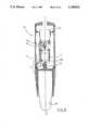
- FIG. 1shows schematically an echographic sector-scan probe according to the present invention
- FIG. 2is a schematical view in longitudinal section of an echographic sector-scan probe, of a mechanical type, according to the present invention
- FIG. 3is a partial longitudinal sectional view of an echographic sector-scan probe, of a mechanical type, according to the present invention
- FIG. 4shows in schematical perspective view an echographic sector-scan probe, of an electronic type, according to the present invention
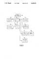
- FIG. 5shows a block diagram of the control circuitry of the apparatus according to the present invention provided with a first kind of echographic sector-scan probe, of a mechanical type;
- FIG. 6shows a block diagram of the control circuitry of the apparatus according to the present invention, provided with a second kind of echographic sector-scan probe, of a mechanical type:
- FIG. 7shows a block diagram of the control circuitry of the apparatus according to the invention, provided with an echographic sector-scan probe, of an electronic type;
- FIG. 8shows a block diagram for an auxiliary circuit for synchronizing the apparatus according to the invention with the heart-beat of a patient
- FIG. 8ashows a flow-chart of the program for synchronizing the apparatus according to the invention with the heart-beats of a patient
- FIG. 8bshows a flow-chart of the program for acquiring a complete series of echographic images with the apparatus according to the present invention, provided with a first kind of echographic sector-scan probe, of a mechanical type;
- FIG. 8cshows a schematic representation of the acquisition process for the three-dimensional reconstruction of the heart in a specified moment of the cardiac cycle with the apparatus according to the present invention
- FIG. 8dshows a schematic representation of the acquisition process for the three-dimensional reconstruction of the heart throughout the entire cardiac cycle with the apparatus according to the present invention
- FIG. 8eshows a flow-chart of the program for acquiring a complete series of echographic images with the apparatus according to the present invention, provided with a second kind of echographic sector-scan probe, of a mechanical type;
- FIG. 8fshows a flow-chart of the program for acquiring a complete series of echographic images with the apparatus according to the present invention, provided with an electronic type of echographic sector-scan probe;
- FIG. 9shows a block diagram of the data processing apparatus and output devices of the apparatus according to the invention.
- FIG. 10shows a flow chart illustrating the general operation of the apparatus according to the present invention.
- FIG. 11shows a schematic representation of the three-dimensional matrix of information obtained with the process shown in FIG. 10.
- a sector-scan echographic probeaccording to the present invention is schematically represented as 10; this probe comprises an outer tubular housing 11 from an end of which an ultrasound transducer 12 protrudes.
- the transducer 12emits a sectorial beam of ultrasound in a conventional manner and it is electrically connected to means for its operation, not shown, through the cable 13.
- the ultrasound transducer 12is rotated around the longitudinal axis L of the probe to collect two-dimensional images in different scanning planes with predetermined angular increments, four of which are shown by way of example in FIG. 1 and identified as 0, 1, 2, 3. With this transducer a series of two-dimensional images is acquired, with a constant angular increment up to covering a rotation of 180°.
- the rotation axiscoincides with the symmetry axis of the two-dimensional sector, a rotation of 180° is sufficient to cover all of the 360° necessary for the three-dimensional reconstruction.
- the angular incrementshould be smaller than the lateral resolution of the ultrasound transducer; thus the total number of the two-dimensional images which are necessary for the reconstruction of the three-dimensional model is 180° divided by the angular increment.
- a first example of a sector-scan probe according to the inventionmay then be realized with a fixed tubular part 11 housing an electric motor 14 rigidly fastened thereto, and a support 15 for an ultrasound transducer 16 rotatably mounted within the fixed part 11 and connected to the motor 14 to be rotated by it.
- a step-down gearbox 17which reduces the number of revolutions of the motor 14 by 120 times is interposed between the motor 14 and the support 15; consequently to each full revolution of the motor 14 corresponds an angular increment of 3° of the probe 16.
- the selection of the step-down ratio of 120:1is a consequence both of the lateral resolution of the transducer used in this construction and of the output power of the motor 14.
- the probe 10is provided with a switch 19 which, actuated by a cam 19a located on the shaft of the support 15, detects the mechanical-zero position of the same.
- the probe 10is also provided with an optical gate 18 of a known type which, in cooperation with a tab 20 fastened to the shaft of the motor 14, allows the control of the number of angular increments to which the transducer 16 is subjected.
- This kind of probemay use either a phased array transducer or a mechanical transducer; in the latter case the transducer is provided with its own motor, as is well known, for permitting the sectorial scanning.
- an electric motorwhich allows both the sectorial scanning of the transducer and the rotation of the same around the longitudinal axis of the probe can be used.
- This embodiment of the present inventionis shown in detail in FIG. 3.
- the outer shell of the end of the probe 10-which envelops the piezoelectric ceramic, the motor, and the several moving components--is indicated as 20.
- a stepper motor 21, or an equivalent oneconnected to an annular support 22 fastened to the interior of the shell 20 of the probe 10 and provided centrally with a tubular extension 22a; within this tubular extension 22a, a wall 23 is fastened that is traversed by the motor shaft 24.
- the plate 22supports rotatably in positions diametrically opposed with respect to the shaft 24, a pair of uprights 25a and 25b, by a ball bearing 26 having its inner ring fastened to the tubular extension 22a of the plate 22.
- a bevel gear 27meshing with a sector bevel gear 28 fastened on a transversal shaft 31 parallel to the pin 29 supported by ball bearings 32 located at the end of the uprights 25a and 25b.
- the sector bevel gear 28is, in its turn, rotatably mounted on a pin 29 at right angles with the shaft 24, fastened to the upright 25a.
- the shaft 31is connected in a known way to the block 33 of piezoelectric elements which emit the ultrasound beam, an assembly that, owing to the above described mechanical interconnections, is provided with a reciprocating oscillatory motion with respect to the axis 7 of the shaft 31.
- a sleevecoaxial with respect to the shaft 24, having an internal edge 34a whereon a helical spring 35 rests, pushing on a collar 36 slidably mounted on the shaft 24.
- annular electromagnet 37fastened to the plate 23
- a disk 38is fastened to the collar 36; the disk 38 is provided with two diametrical seats 39 suitable to be engaged by two corresponding teeth 40 protruding from a body 41 integral with the toothed gear 27 and consequently with the shaft 24.
- the disk 38is moreover slidably engaged with two pins 42 extending from the uprights 25a and 25b so that said disk is firmly connected with said uprights.
- the stepper motor 21gives to the shaft 24 a reciprocating angular motion that, in the scanning phase, is transmitted to the group of piezoelectric elements 33, while the electromagnet 37 is energized, thus preventing the transmission of the motion also to the two uprights 25a and 25b, because the disk 38, attracted by the electromagnet 37, is disengaged from the body 41.
- the stepper motoris stopped in the intermediate position, i.e. the position in which the group 33 is in the horizontal position, the electromagnet 37 is deenergized, and consequently the disk 38, pushed by the spring 35, engages the body 41.
- an electronic sector-scan probe 10is schematically represented with the transducer 50, constituted of a matrix of piezoelectric elements; on this matrix a vector 51 of elements that identifies the scanning plane can be selected electronically.
- the transducermay also be realized by means of arrays of piezoelectric elements, constituted of at least two arrays crossing each other at the center of the transducer.
- the selection of the scanning planes passing through the centeris obtained by firing the single elements of each array with variable delays, as it is usually done in the conventional electronic transducers.
- an electronic systemfor the serial acquisition of the echographic images by either controlling the motion of the motor which rotates the transducer or selecting the correct vector of the ceramic elements of the matrix; the same electronic system also allows the acquisition of orthogonal two-dimensional images that are necessary for the standard two-dimensional echographic examination, thus avoiding the manual rotation of the probe.
- the apparatus(refer to FIG. 5) comprises means for the two-dimensional scanning, which control the sectorial scanning motor.
- the apparatusmoreover, includes an electronic circuit dedicated to the rotation of the transducer 16.
- This circuitindicated as transducer rotation adapter, feeds the motor 14 dedicated to the rotation, while a control circuit, associated to a rotation sensor constituted by an optical gate 18 and a tab 20 fastened to the shaft of the motor 14, allows the clockwise or counterclockwise rotation of the transducer by the corresponding switches.
- FIGS. 5 and 6relating to circuitries for the control of the echographic probes shown in FIGS. 2 and 3, respectively.
- the block diagram therein shownincludes a block 10 indicating generally an echographic probe 10 like the one shown in FIG. 2.
- the probe 10is represented divided into three blocks respectively indicated as 100, corresponding to a mechanical sector-scan transducer; 101, corresponding to the electric motor 14 for the transducer rotation; and 102 corresponding to the optical gate 18.
- the transducer contained in the block 100is controlled by a two-dimensional echographic system of a state-of-the-art type schematically shown as 103.
- the system 103is provided with an input 104 for an electrocardiographic (ECG) signal for synchronizing its operation with the heart-beat of a patient, as will be described hereinafter in greater detail.
- ECGelectrocardiographic
- the system 103is provided with a video output 105 constituted by a conventional composite video signal containing video information, line synchronizing pulses and frame/field synchronizing pulses.
- the video signal present on the output 105is applied to a conventional synchronism separator circuit 106 from which line synchronism signals and frame synchronism signals are obtained, which are applied to a group of counters, represented with block 107, for controlling a character generator 108.
- the character generator 108is also supplied with a signal on line 109 coming from the transducer rotation controller, as will be seen below.
- the output 110 of the character generator 108is applied to a first input combiner circuit 111, the other input of which is supplied with the composite video signal available on the output 105 of block 103.
- the output 112 of the combiner circuit 111is constituted by frames of pictures of two-dimensional scanning "labelled" with information about their angular location with reference to a predetermined "zero position" derived from the echographic probe itself.
- the transducer angular positionis sent to the character generator 108 from block 113 which controls the rotation of the motor 14 contained within the echographic probe through line 109.
- Block 113is associated to the function keyboard 115 that controls the acquisition modalities.
- the usercan select the acquisition of a single frame in each cardiac cycle or the acquisition of the entire cardiac cycle. In the former situation, the user must select a time-delay by a digital switch in order to start the echographic acquisition at different times from the onset of the QRS wave.
- the keyboardhas a switch to inform the rotation controller if a patient is in atrial fibrillation because in this pathological condition it is impossible to recognize the extrasystolic beats comparing the cardiac cycle duration.
- the block 113also controls the rotation speed and direction of the motor 14 by its power supply.
- Block 113is also fed with an ECG synchronism signal 114 derived from the system 103 when it is necessary to execute the echographic scans in synchronism with the heart-beat.
- the rotation controller 113sends a synchronism signal through line 116 to the two-dimensional echographic system 103 to start the sectorial scanning of transducer 16 in synchronism with the ECG signal, if necessary for the three-dimensional reconstruction.
- the selection of an ECG gated acquisitionis performed by operating a switch on the keyboard 115.
- FIG. 6,which relates to a control circuitry for an echographic probe as shown in FIG. 3, will now be explained.
- the circuitry of FIG. 6is arranged to cooperate with an echographic probe comprising a stepper motor 21, indicated as block 200, a selector of scanning/rotation planes represented by block 201 electrically constituted by an electromagnet (see FIG. 3) and a block 202 representing the piezoelectric transducer 33.
- the circuitry of FIG. 6is centered on a microprocessor indicated as a whole with block 203.
- the microprocessor 203controls a counter for the sectorial scanning, indicated as block 204, and a counter for the rotation control, indicated as block 205.
- the outputs of counters 204 and 205are combined together in the combining block 206 for controlling a stepper motor driver, indicated as block 207.
- the four-phase power signals 206which command the stepping motor contained in block 200 output from block 207.
- the piezoelectric transducer contained in block 202is connected through a bidirectional line 217 to a two-dimensional image generator 208, which is also connected to the microprocessor 203 through a bus 209, and to an image memory unit 210 through a bus 211.
- Memory 210is associated to a further graphic memory 212, controlled with a line 213 by the microprocessor 203, for the "labelling" of the images stored in the memory 210 in a manner similar to that described with reference to FIG. 5.
- the outputs of the memories 210, 212are combined at the node 214 to provide a combined video signal output 215 as disclosed with reference to FIG. 5.
- microprocessor 203is provided with an input for an electrocardiographic synchronism signal 216 for use when it is necessary to synchronize the scans with the heart-beat and it is connected to a function keyboard 218 to select the acquisition modalities.
- the circuitry of FIG. 7is arranged to cooperate with an echographic probe comprising an array of piezoelectric elements 51 (block 250), driven by a multiplexer 251 fed on one hand through a bundle 252 of coaxial cables by a transmit/receive generator of the delay for the sectorial scanning shown in 253.
- the multiplexer 251is also driven through a bus 254 by a selector of the scanning direction shown in block 255 and controlled through a bus 256 by a CPU 257.
- the CPU 257also controls, through a further bus 258, both said delay generator 253 and a polar-to-rectangular scan converter 259.
- the latteris also fed with echo data from block 253 by means of a bus 260.
- the scan converter 259is connected with a bus 261 to an image memory 262 from which serial video signals are outputted over line 263.
- a line 264brings to the CPU 257 a signal for the synchronization with the ECG signal and a function keyboard 265 allows the selection of different acquisition modalities.
- FIG. 8shows a circuit for deriving the synchronism signals from the ECG signals.
- the ECG signalis applied on input terminal 300, from which it is applied to a first filter unit 301 for suppressing unwanted high-frequency noise components.
- the output of the filter 301is applied to the input 302 of a variable gain amplifier 303 whose gain may be adjusted by means of a control 304.
- the output of the amplifier 303is applied to a filter 305 of the bandpass type, arranged for enhancing the pulse component of the QRS wave.
- the output of the filter 305is then applied to a QRS detector 306 comprising, in a known way, a threshold detector and a waveshaper, for providing on the output 307 a signal suitable for synchronizing the operation of the ultrasonic echographic scanner as above described.
- a QRS detector 306comprising, in a known way, a threshold detector and a waveshaper, for providing on the output 307 a signal suitable for synchronizing the operation of the ultrasonic echographic scanner as above described.
- the ECG synchronismis processed in accord with the function keyboard setting prearranged by the user as described below.
- FIG. 8ashowing the processing arrangement of the ECG synchronism signals to reconstruct the three-dimensional model of the heart in a specified moment of the cardiac cycle.
- the execution of the program shown in the flow-chart of FIG. 8ais started by the program controlling the acquisition of the two-dimensional images when the operator selects the ECG-gated modality and he presses the START key on the function keyboard.
- the programchecks if the user pushed the function keyboard key to indicate the presence of atrial fibrillation (box 700); if the key is not depressed, the program calculates the mean cardiac cycle duration on 10 consecutive beats (box 701) to obtain a reference value to identify the presence of arrhythmias during the acquisition process.
- the programIn the presence of atrial fibrillation--indicated by a depressed key in the function keyboard--the program does not calculate the mean cardiac cycle duration because, in this pathological condition, it is impossible to identify extrasystolic beats by comparing the cardiac cycle duration.
- the programwaits (box 702) until it receives an ECG synchronism signal from the circuit described in FIG. 8 and, if atrial fibrillation is not present (box 703), it calculates the cardiac cycle duration (box 704) to check for arrhythmias (box 705).
- a heart beatis defined arrhythmic if the cycle duration differs more than 10% from the mean cardiac cycle duration.
- the programrejects the postextrasystolic cycle coming back to the connection point 706. If the heart beat is rhythmic, the program sends the ECG synchronism to the microprocessor controlling the acquisition of the two-dimensional echograms (box 707).
- the microprocessorprocesses the ECG synchronism signals differently in accordance with the different systems presented in FIGS. 5, 6 and 7; moreover, the process differs if the user selected the acquisition of a single frame or of an entire cardiac cycle.
- the programcalculates the cardiac cycle duration (box 710); then, if the rhythm is irregular (box 711), it sends an error message to the microprocessor to reject the last acquisition (box 712). In any case, the program sends a synchronism signal to the microprocessor to indicate the cardiac cycle end (box 713).
- the program stepstarting from the connection point 706, is repeated until the program receives a stop signal (box 714) from the microprocessor controlling the acquisition as described below.
- FIG. 8bshows the flow-chart of the program controlling the acquisition process of a system represented in FIG. 5 using a mechanical sector scanner transducer of the type shown in FIG. 2.
- the programis activated when the user pushes the START key on the function keyboard 218 (box 800).
- the programstops the sector scanning of the transducer (box 801) by sending a signal to the two-dimensional echographic system through the line 116.
- the rotation controller 113rotates the motor 14 to reset the transducer scanning plane in the starting position corresponding to 0 degrees rotation (box 802).
- the programstarts the execution of the ECG synchronism program described before (see FIG.
- the programchecks if a single frame or an entire cardiac cycle must be acquired (box 809). For a single frame acquisition, the program waits for the ECG synchronism signal (box 810) and, thus, it acquires a single image sending the start and stop signal to the two-dimensional echographic system 103 through the line 116 (boxes 811 and 812).
- the programchecks for the presence of an arrhythmia (box 814); if the rhythm is regular, the system rotates the transducer (box 815), otherwise it repeats the acquisition with the same transducer angular position.
- the execution of the ECG synchronism programis stopped (box 817).
- the program branch ranging from box 810 to box 816performs the acquisition of 60 images synchronized with the ECG as indicated in FIG. 8c.
- the programacquires an image every two cardiac cycles while, during the interposed cycles, the transducer is rotated in the next angular position. Therefore, to acquire the 60 images over an entire rotation of 180°, the system needs 120 cardiac cycles; the acquisition time is 72 to 120 seconds for a patient in sinus rhythm (heart rate ranging from 60 to 100 beats/second).
- the delay between the onset of the QRS and the acquisition timeis selected by the digital switch on the function keyboard. If the user selects the ECG-gated acquisition of an entire cardiac cycle to reconstuct the heart during the entire cycle, the branch program ranging from box 818 to box 824 performs the acquisition of 60 cycles synchronized with the ECG as indicated in FIG. 8d.
- the systemacquires an entire cardiac cycle starting from the onset of the QRS wave and ending with the onset of the next QRS wave; the time during the next cycle is used to rotate the transducer. As in FIG. 8c, this process is repeated 60 times for a total of 120 cardiac cycles.
- the algorithm for the system presented in FIG. 6, using a probe like the one shown in FIG. 3,is similar to the flow-chart presented in FIG. 8b.
- the main differenceis in the control of the acquisition/rotation sequence.
- the programmust drive the rotation/scanning selector and the motor (21) inside the probe to switch between the acquisition and the rotation status of the probe.
- FIG. 7connected to an electronic transducer with a matrix of piezoelectric elements (FIG. 4) is controlled by the program shown in FIG. 8f.
- This flow-chartis similar to the FIG. 8b with the difference that the rotation of the scanning plane is realized selecting a different array of piezoelectric elements without any mechanical movement.
- FIG. 8eshows the flow-chart of the program controlling the acquisition process of a system represented in FIG. 6 using a mechanical sector-scanner transducer of the type shown in FIG. 3.
- the programis activated when the user pushes the START key on the function keyboard 218 (box 830).
- the programinterrupts the sectorial scanning of the transducer (box 831) by stopping the motor 21 when the transducer 33 is in the horizontal position.
- the rotation/scanning selectoris switched in the rotation position (box 832) and the scanning plane is rotated to the starting position corresponding to 0° rotation (box 833).
- the programstarts the execution of the ECG synchronism program described before (see FIG.
- the programacquires a single image driving the motor 21 connected with the transducer 33 (box 844).
- the programchecks for the presence of an arrhythmia (box 846); if the rhythm is regular, the system rotates the transducer switching the rotation/scanning selector to the rotation position (box 847) and incrementing the scanning plane angular position (box 848), otherwise it repeats the acquisition with the same transducer angular position. This acquisition process is repeated until a complete rotation of 180° is realized (box 849); then, the execution of the ECG synchronism program is stopped (box 850) and the process terminates.
- the programswitches the rotation/scanning selector to the scanning position (box 851) and it waits for the ECG syncrhonism (box 852).
- the programstarts the acquisition of multiple images driving the motor 21 (box 853) until the next ECG synchronism is received (box 854).
- the programinterrupts the image acquisition stopping the motor 21 connected with the transducer 33 (box 855).
- FIG. 8fshows the flow-chart of the program controlling the acquisition process of a system represented in FIG. 7 using an electronic sector-scanner transducer with a matrix of piezoelectric elements of the type shown in FIG. 4.
- the programis activated when the user pushes the START key on the function keyboard 265 (box 860).
- the programstops the sectorial scanning of the transducer and it selects the array of piezoelectric elements corresponding to 0° rotation (box 861). If the user selected an ECG-gated acquisition (box 862), the program starts the execution of the ECG synchronism program described before (see FIG. 8a) (box 863); otherwise the program acquires immediately an image on the current scanning plane (box 864).
- the scanning planeis rotated (box 865) and a new image is acquired until a complete rotation of 180° is realized (box 866).
- the programchecks if a single frame or an entire cardiac cycle must be acquired (box 867). For a single frame acquisition, the program waits for the ECG synchronism signal (box 868) When the ECG synchronism signal is received, the program acquires a single image (box 869).
- the programchecks for the presence of an arrhythmia (box 871); if the rhythm is regular, the system selects the next array of piezoelectric elements to rotate the scanning plane (box 872), otherwise it repeats the acquisition with the same transducer angular position. This acquisition process is repeated until a complete rotation of 180° is realized (box 873); then, the execution of the ECG synchronism program is stopped (box 874) and the process terminates. If the entire cardiac cycle acquisition is selected (box 867), the program waits for the ECG synchronism (box 875).
- the programstarts the acquisition of multiple images (box 876) until the next ECG synchronism is received (box 854).
- the programstops the image acquisition (box 878). If the rhythm is irregular (box 879), the acquisition is repeated with the same transducer angular position; otherwise, the scanning plane is rotated selecting the next array of piezoelectric elements (box 880). The acquisition/rotation sequence is repeated until a rotation of 180° is realized (box 881).
- the execution of the ECG synchronism programis stopped (box 874).
- FIG. 9showing the data processing arrangement for obtaining the three-dimensional reconstruction of echographic images from the data collected according to the apparatus and methods hereinbefore disclosed.
- FIG. 9shows a general purpose computing unit which could be realized either as a separate unit or incorporated in the processor-controlled units for obtaining two-dimensional echographic images.
- the data processing unitcomprises a CPU 400 of a structure well known in the art, connected to an input/output unit 401.
- the input/output unit 401is connected with:
- a frame grabber 402that digitizes the two-dimensional echographic images processed by the echographic unit 402;
- a keyboard 404to input various controls and commands to the apparatus
- a mass storage unitconsisting of a magnetic tape streamer 405;
- a video controller 407connected to a video monitor 408 either monochrome or color type; and, possibly, with
- the CPU 400operates under the control of software means either residing on a read only memory (not shown) or a random access memory, bootstrapped from a floppy disk unit (not shown).
- FIG. 10is shown a flow chart showing the operating program controlling the CPU 400 of FIG. 9.
- the program shown in the flow-chart of FIG. 10starts from box 500 at the statement that the rotating echographic scanning head is at its home position corresponding to the zero angular position.
- the digitization of a two-dimensional imageis performed, for instance in a format of 512 ⁇ 512 pixels with 256 levels of grey (8 bits) (box 501).
- This imageis memorized (box 502) for instance in a RAM memory with the insertion of additional information, e.g. the angular position of the scanning head (zero degrees in the first run of the loop).
- the angular position of the scanning headis incremented through a predetermined angle, in a preferred embodiment through an angle of 3°. This process continues through 3° increment steps up to when the decision box 504 recognizes that the entire scanning of 180° has been performed. If the scanning is lower than 180° the loop repeats through line 505 which combines in 506 at the transition from box 500 to box 501.
- box 507a second processing step starts. Beginning with a polar plane equal to 1 (box 507) a selection is performed in box 508, in all the two-dimensional images, of the vectors corresponding to horizontal planes corresponding to the current polar plane identified by the loop returning on line 509 from decision box 510 to combination point 511.
- box 508The processing performed in box 508 is followed by a transformation of the vector coordinates from polar into cartesian ones (box 512). This is followed in box 513 by an interpolation of the above mentioned vector for the build-up of one polar image comprising 512 ⁇ 512 pixels. In box 514 an increment of the polar plane occurs, so that the operations of boxes 508, 512 and 513 are repeated until reaching a polar plane greater than 512, expressed by decision box 510.
- a three-dimensional matrix with 512 ⁇ 512 ⁇ 512 pixels (128 M bytes)is available and ready to be stored on a hard disk unit (block 406 of FIG. 9) (box 515).
- the block of information which is built according to the inventionis better shown in FIG. 11 as being constituted by a "cube" matrix having its sides 512 bytes long, wherein a "cone” 600 of information is enclosed, constituted by a number of scan planes 601, 602, 603 etc., corresponding to the single scan planes of the echographic probe before disclosed.
- the "cone” 600has an apex 605 which corresponds to the tip of the probe lying against the body of a patient.
- Within the “cone” 600is contained all the information representative of an anatomic structure schematized by a roughly represented heart 606.
- a desired sectionmay be obtained, for instance along the plane "128", thus obtaining a sectional view of the heart as shown in shadow in 607.
- any other plane of sectioncan be derived from the block of information schematically shown in FIG. 11.
- Section planesmay be derived having different inclinations and orientation that have not been shown in FIG. 11 for the sake of clarity.
- the "cone” 600contains all the information about the anatomical structure, derived from the successive scans performed through an angle of 180° as previously described.
- the algorithum described in FIG. 10is applied to each frame of an entire cardiac cycle, a three-dimensional reconstruction of the heart in each moment of its cycle can be obtained.
- the apparatus according to the inventionmay also be used for the three-dimensional reconstruction of the blood flow utilizing a sector-scan probe color-coded for flow mapping by Doppler.
- the colour flow mapping two-dimensional Doppler echographic apparatusprovide a two-dimensional image with superimposed a colour-coded map of the blood flows wherein the different colours encode different flow speeds and directions with respect to the transducer itself.
- This kind of representationallows the visualization of a section of the contour of the blood flow corresponding to the sectorial scanning plane, but does not provide any information about its actual extension and orientation in space.
- the acquisition of a plurality of two-dimensional images with a colour map of the blood flow, using a Doppler transducer according to the inventionallows the complete reconstruction of the three-dimensional contour of the blood flow under examination. Even with the transducer according to the invention, however, if the blood flow is exclusively perpendicular to the direction of the interrogating ultrasonic beam, it cannot be detected since the frequency shift produced by the Doppler effect is zero.
- the apparatus according to the inventionmay be provided with an "invasive" probe, either flexible or rigid, of the rotating type with arrays of piezoelectric elements, or it can be provided with a probe of the fixed type having mounted on it a three-dimensional array of piezoelectric elements, so that it can be utilized, during invasive examinations, for the volumetric acquisition of signals produced by reflection and/or scattering from internal parts of anatomic structures.
- an "invasive" probeeither flexible or rigid, of the rotating type with arrays of piezoelectric elements, or it can be provided with a probe of the fixed type having mounted on it a three-dimensional array of piezoelectric elements, so that it can be utilized, during invasive examinations, for the volumetric acquisition of signals produced by reflection and/or scattering from internal parts of anatomic structures.
- the apparatus according to the present inventionbesides the study of any organ of the human or animal body, may be conveniently used for non destructive tests in any other technical field.
Landscapes
- Engineering & Computer Science (AREA)
- Physics & Mathematics (AREA)
- Health & Medical Sciences (AREA)
- Life Sciences & Earth Sciences (AREA)
- Remote Sensing (AREA)
- Radar, Positioning & Navigation (AREA)
- Acoustics & Sound (AREA)
- Biophysics (AREA)
- General Physics & Mathematics (AREA)
- Computer Networks & Wireless Communication (AREA)
- Surgery (AREA)
- Heart & Thoracic Surgery (AREA)
- Medical Informatics (AREA)
- Animal Behavior & Ethology (AREA)
- General Health & Medical Sciences (AREA)
- Public Health (AREA)
- Veterinary Medicine (AREA)
- Molecular Biology (AREA)
- Biomedical Technology (AREA)
- Cardiology (AREA)
- Pathology (AREA)
- Nuclear Medicine, Radiotherapy & Molecular Imaging (AREA)
- Radiology & Medical Imaging (AREA)
- Multimedia (AREA)
- Physiology (AREA)
- Ultra Sonic Daignosis Equipment (AREA)
Abstract
Description
Claims (26)
Applications Claiming Priority (2)
| Application Number | Priority Date | Filing Date | Title |
|---|---|---|---|
| IT953288 | 1988-11-25 | ||
| IT09532A/88 | 1988-11-25 |
Publications (1)
| Publication Number | Publication Date |
|---|---|
| US5159931Atrue US5159931A (en) | 1992-11-03 |
Family
ID=11131749
Family Applications (1)
| Application Number | Title | Priority Date | Filing Date |
|---|---|---|---|
| US07/438,292Expired - LifetimeUS5159931A (en) | 1988-11-25 | 1989-11-20 | Apparatus for obtaining a three-dimensional reconstruction of anatomic structures through the acquisition of echographic images |
Country Status (1)
| Country | Link |
|---|---|
| US (1) | US5159931A (en) |
Cited By (201)
| Publication number | Priority date | Publication date | Assignee | Title |
|---|---|---|---|---|
| US5211063A (en)* | 1989-12-06 | 1993-05-18 | Baumer Electric Ag | Measuring device with several sensors in multiplex |
| DE4344312A1 (en)* | 1992-12-24 | 1994-07-14 | London Health Ass | Ultrasonic scanner for medical diagnostics of eye or prostate |
| US5379771A (en)* | 1993-04-06 | 1995-01-10 | Kabushiki Kaisha Toshiba | Ultrasonic imaging apparatus |
| US5396890A (en)* | 1993-09-30 | 1995-03-14 | Siemens Medical Systems, Inc. | Three-dimensional scan converter for ultrasound imaging |
| US5454371A (en)* | 1993-11-29 | 1995-10-03 | London Health Association | Method and system for constructing and displaying three-dimensional images |
| US5465724A (en) | 1993-05-28 | 1995-11-14 | Acuson Corporation | Compact rotationally steerable ultrasound transducer |
| US5474073A (en)* | 1994-11-22 | 1995-12-12 | Advanced Technology Laboratories, Inc. | Ultrasonic diagnostic scanning for three dimensional display |
| US5479929A (en)* | 1994-06-27 | 1996-01-02 | Acuson Corporation | Drive system with a multiturn rotary stop |
| WO1996000402A1 (en)* | 1993-11-29 | 1996-01-04 | Victoria/University Hospital Corporation | Three-dimensional ultrasound imaging system |
| US5485842A (en)* | 1994-11-30 | 1996-01-23 | Advanced Technology Laboratories, Inc. | Ultrasonic diagnostic scan conversion for three dimensional display processing |
| US5487388A (en)* | 1994-11-01 | 1996-01-30 | Interspec. Inc. | Three dimensional ultrasonic scanning devices and techniques |
| US5501222A (en)* | 1994-05-13 | 1996-03-26 | Briggs; Keith A. | System for imaging a region |
| FR2735966A1 (en)* | 1994-11-10 | 1997-01-03 | By Heart | ECHOGRAPHIC METHOD AND DEVICE FOR IMPLEMENTING THREE-DIMENSIONAL HEART ECHOGRAPHY |
| EP0749722A3 (en)* | 1995-06-22 | 1997-04-16 | Hewlett Packard Co | Handheld transthoracic rotatable ultrasound transducer |
| US5655535A (en)* | 1996-03-29 | 1997-08-12 | Siemens Medical Systems, Inc. | 3-Dimensional compound ultrasound field of view |
| EP0795296A1 (en)* | 1996-03-13 | 1997-09-17 | Advanced Technology Laboratories, Inc. | Ultrasonic scanning of tissue motion in three dimensions |
| WO1998000064A3 (en)* | 1996-06-28 | 1998-03-05 | Mayo Foundation | Volumetric image ultrasound transducer underfluid catheter system |
| US5779641A (en)* | 1997-05-07 | 1998-07-14 | General Electric Company | Method and apparatus for three-dimensional ultrasound imaging by projecting filtered pixel data |
| US5797845A (en)* | 1996-11-04 | 1998-08-25 | Barabash; Leonid S. | Ultrasound apparatus for three dimensional image reconstruction |
| WO1998040760A1 (en)* | 1997-03-11 | 1998-09-17 | Sonometrics Corporation | System for displaying a 2-d ultrasound image within a 3-d viewing environment |
| US5842473A (en)* | 1993-11-29 | 1998-12-01 | Life Imaging Systems | Three-dimensional imaging system |
| US5871019A (en)* | 1996-09-23 | 1999-02-16 | Mayo Foundation For Medical Education And Research | Fast cardiac boundary imaging |
| US5876345A (en)* | 1997-02-27 | 1999-03-02 | Acuson Corporation | Ultrasonic catheter, system and method for two dimensional imaging or three-dimensional reconstruction |
| EP0736284A3 (en)* | 1995-04-03 | 1999-06-16 | Hans Dr. Polz | Method and device for detection of diagnostically usable three dimensional ultrasonic picture data set |
| US5924991A (en)* | 1997-08-22 | 1999-07-20 | Acuson Corporation | Ultrasonic system and method for harmonic imaging in three dimensions |
| EP0797106A3 (en)* | 1996-03-22 | 1999-09-15 | Advanced Technology Laboratories, Inc. | Three dimensional medical ultrasonic diagnostic imaging of tissue texture and vasculature |
| EP0945104A1 (en)* | 1998-03-25 | 1999-09-29 | Sulzer Osypka GmbH | System and method for visualising the activity of an organ |
| US5989191A (en)* | 1998-06-19 | 1999-11-23 | Hewlettt-Packard Company | Using doppler techniques to measure non-uniform rotation of an ultrasound transducer |
| US5993390A (en)* | 1998-09-18 | 1999-11-30 | Hewlett- Packard Company | Segmented 3-D cardiac ultrasound imaging method and apparatus |
| EP0961135A1 (en)* | 1998-03-30 | 1999-12-01 | TomTec Imaging Systems GmbH | Method and apparatus for ultrasound image acquisition |
| US6014473A (en)* | 1996-02-29 | 2000-01-11 | Acuson Corporation | Multiple ultrasound image registration system, method and transducer |
| WO2000011495A1 (en)* | 1998-08-21 | 2000-03-02 | Tomtec Imaging Systems Gmbh | Method and device for recording ultrasonic images |
| US6036646A (en)* | 1998-07-10 | 2000-03-14 | Guided Therapy Systems, Inc. | Method and apparatus for three dimensional ultrasound imaging |
| US6045508A (en)* | 1997-02-27 | 2000-04-04 | Acuson Corporation | Ultrasonic probe, system and method for two-dimensional imaging or three-dimensional reconstruction |
| US6059728A (en)* | 1997-01-02 | 2000-05-09 | Storz Instrument Co. | Three-dimensional ultrasound imaging system and probe |
| US6059731A (en)* | 1998-08-19 | 2000-05-09 | Mayo Foundation For Medical Education And Research | Simultaneous side-and-end viewing underfluid catheter |
| US6080108A (en)* | 1998-11-17 | 2000-06-27 | Atl Ultrasound, Inc. | Scanning aid for quantified three dimensional ultrasonic diagnostic imaging |
| US6116244A (en)* | 1998-06-02 | 2000-09-12 | Acuson Corporation | Ultrasonic system and method for three-dimensional imaging with opacity control |
| US6122538A (en)* | 1997-01-16 | 2000-09-19 | Acuson Corporation | Motion--Monitoring method and system for medical devices |
| US6139500A (en)* | 1999-02-24 | 2000-10-31 | Agilent Technologies Inc. | Methods and apparatus for 3D cardiac ultrasound imaging |
| US6171247B1 (en) | 1997-06-13 | 2001-01-09 | Mayo Foundation For Medical Education And Research | Underfluid catheter system and method having a rotatable multiplane transducer |
| US6174285B1 (en) | 1999-02-02 | 2001-01-16 | Agilent Technologies, Inc. | 3-D ultrasound imaging system with pre-set, user-selectable anatomical images |
| US6193661B1 (en) | 1999-04-07 | 2001-02-27 | Agilent Technologies, Inc. | System and method for providing depth perception using single dimension interpolation |
| US6194814B1 (en) | 1998-06-08 | 2001-02-27 | Acuson Corporation | Nosepiece having an integrated faceplate window for phased-array acoustic transducers |
| US6198956B1 (en) | 1999-09-30 | 2001-03-06 | Oti Ophthalmic Technologies Inc. | High speed sector scanning apparatus having digital electronic control |
| US6228028B1 (en) | 1996-11-07 | 2001-05-08 | Tomtec Imaging Systems Gmbh | Method and apparatus for ultrasound image reconstruction |
| WO2001033251A1 (en)* | 1999-11-03 | 2001-05-10 | Koninklijke Philips Electronics N.V. | Uniform volumetric scanning ultrasonic diagnostic imaging system |
| US6306096B1 (en) | 1991-11-08 | 2001-10-23 | Mayo Foundation For Medical Education And Research | Volumetric image ultrasound transducer underfluid catheter system |
| EP1167996A1 (en)* | 2000-06-22 | 2002-01-02 | Esaote S.p.A. | Method and apparatus for ultrasound imaging, particularly for three-dimensional imaging |
| US20020049375A1 (en)* | 1999-05-18 | 2002-04-25 | Mediguide Ltd. | Method and apparatus for real time quantitative three-dimensional image reconstruction of a moving organ and intra-body navigation |
| US6398736B1 (en) | 1999-03-31 | 2002-06-04 | Mayo Foundation For Medical Education And Research | Parametric imaging ultrasound catheter |
| US6409669B1 (en) | 1999-02-24 | 2002-06-25 | Koninklijke Philips Electronics N.V. | Ultrasound transducer assembly incorporating acoustic mirror |
| USD462446S1 (en) | 2001-09-19 | 2002-09-03 | Novasonics, Inc. | Handheld ultrasonic transducer with bulb grip |
| WO2002069807A1 (en)* | 2001-03-06 | 2002-09-12 | Easymedics Corporation | Three-dimensional image detecting apparatus using position sensor |
| USD467002S1 (en) | 2001-09-19 | 2002-12-10 | Novasonics, Inc. | Handheld ultrasonic transducer with curved bulb grip |
| USD469539S1 (en) | 2001-08-31 | 2003-01-28 | Novasonics, Inc. | Handheld ultrasonic display device |
| USD469877S1 (en) | 2001-08-31 | 2003-02-04 | Novasonics, Inc. | Handheld ultrasonic display device with cover |
| US6547735B1 (en) | 2001-12-05 | 2003-04-15 | Koninklijke Philips Electronics N.V. | Partial rayline volumetric scanning ultrasonic diagnostic imaging system |
| WO2002007586A3 (en)* | 2000-07-21 | 2003-07-10 | Diagnostic Ultrasound Corp | System for remote programming of ultrasound devices |
| US6602194B2 (en) | 2000-09-15 | 2003-08-05 | Koninklijke Philips Electronics N.V. | Dual beamformer ultrasound system for 2D and 3D imaging |
| US6626834B2 (en) | 2001-01-25 | 2003-09-30 | Shane Dunne | Spiral scanner with electronic control |
| US6679849B2 (en) | 2001-07-31 | 2004-01-20 | Koninklijke Philips Electronics N.V. | Ultrasonic tee probe with two dimensional array transducer |
| US20040054280A1 (en)* | 2002-09-18 | 2004-03-18 | Mcmorrow Gerald J. | Three-dimensional system for abdominal aortic aneurysm evaluation |
| US6723050B2 (en) | 2001-12-19 | 2004-04-20 | Koninklijke Philips Electronics N.V. | Volume rendered three dimensional ultrasonic images with polar coordinates |
| US20040081340A1 (en)* | 2002-10-28 | 2004-04-29 | Kabushiki Kaisha Toshiba | Image processing apparatus and ultrasound diagnosis apparatus |
| US6755787B2 (en) | 1998-06-02 | 2004-06-29 | Acuson Corporation | Medical diagnostic ultrasound system and method for versatile processing |
| US20040138548A1 (en)* | 2003-01-13 | 2004-07-15 | Mediguide Ltd. | Method and system for registering a medical situation associated with a first coordinate system, in second coordinate system using an MPS system |
| US6780153B2 (en)* | 2001-06-25 | 2004-08-24 | Angelsen Bjoern A. J. | Mechanism and system for 3-dimensional scanning of an ultrasound beam |
| US20040204650A1 (en)* | 2001-10-16 | 2004-10-14 | Taylor James D. | Scanning probe |
| US20040225219A1 (en)* | 2003-05-08 | 2004-11-11 | Demers Douglas Armand | Volumetric ultrasonic image segment acquisition with ECG display |
| US20040243147A1 (en)* | 2001-07-03 | 2004-12-02 | Lipow Kenneth I. | Surgical robot and robotic controller |
| US20040254466A1 (en)* | 2003-06-16 | 2004-12-16 | James Boner | Apparatus and method for real time three-dimensional ultrasound imaging |
| US20040267123A1 (en)* | 2003-06-27 | 2004-12-30 | Mcmorrow Gerald J. | System for aiming ultrasonic bladder instruments |
| US20050004465A1 (en)* | 2003-04-16 | 2005-01-06 | Eastern Virginia Medical School | System, method and medium for generating operator independent ultrasound images of fetal, neonatal and adult organs |
| US20050049503A1 (en)* | 2003-08-28 | 2005-03-03 | Armin Schoisswohl | Method and apparatus for obtaining a volumetric scan of a periodically moving object |
| WO2005050252A1 (en)* | 2003-11-20 | 2005-06-02 | Koninklijke Philips Electronics, N.V. | Ultrasonic diagnostic imaging with automatic adjustment of beamforming parameters |
| WO2005050619A1 (en)* | 2003-11-21 | 2005-06-02 | Koninklijke Philips Electronics, N.V. | Three-dimensional ultrasonic imaging using mechanical probes with beam scanning reversal |
| US20050124889A1 (en)* | 2003-12-05 | 2005-06-09 | Aime Flesch | Array transducer for 3D tilting probes |
| US20050123189A1 (en)* | 2002-03-14 | 2005-06-09 | Dieter Bayer | Method and device for reconstructing and representing multidimensional objects from one-dimensional or two-dimensional image data |
| US20050137478A1 (en)* | 2003-08-20 | 2005-06-23 | Younge Robert G. | System and method for 3-D imaging |
| US20050251036A1 (en)* | 2003-04-16 | 2005-11-10 | Eastern Virginia Medical School | System, method and medium for acquiring and generating standardized operator independent ultrasound images of fetal, neonatal and adult organs |
| US20050283078A1 (en)* | 2004-06-22 | 2005-12-22 | Steen Eric N | Method and apparatus for real time ultrasound multi-plane imaging |
| US6980844B2 (en) | 2003-08-28 | 2005-12-27 | Ge Medical Systems Global Technology Company | Method and apparatus for correcting a volumetric scan of an object moving at an uneven period |
| US20060020202A1 (en)* | 2004-07-06 | 2006-01-26 | Mathew Prakash P | Method and appartus for controlling ultrasound system display |
| US20060058647A1 (en)* | 1999-05-18 | 2006-03-16 | Mediguide Ltd. | Method and system for delivering a medical device to a selected position within a lumen |
| EP1596718A4 (en)* | 2002-11-05 | 2006-05-10 | Diagnostic Ultrasound Corp | 3d ultrasound-based instrument for non-invasive measurement of amniotic fluid volume |
| US20060241424A1 (en)* | 2003-03-20 | 2006-10-26 | Matsushita Electric Industrial Co., Ltd. | Ultrasonic probe and ultrasonographic device |
| US20060241465A1 (en)* | 2005-01-11 | 2006-10-26 | Volcano Corporation | Vascular image co-registration |
| US20060241453A1 (en)* | 2005-04-08 | 2006-10-26 | Vermon | Ultrasonic probe for scanning a volume |
| US20070010743A1 (en)* | 2003-05-08 | 2007-01-11 | Osamu Arai | Reference image display method for ultrasonography and ultrasonograph |
| US20070032724A1 (en)* | 2003-06-03 | 2007-02-08 | Koninklijke Philips Electronics N.V. | Synchronizing a swiveling three-dimensional ultrasound display with an oscillating object |
| US20070038112A1 (en)* | 2001-10-16 | 2007-02-15 | Taylor James D | Scanning probe with integrated electronics |
| US20070062290A1 (en)* | 2005-08-30 | 2007-03-22 | Ultrasonic Technologies Ltd. | Motor driven mechanism for mechanically scanned ultrasound transducers |
| US20070068253A1 (en)* | 2005-09-15 | 2007-03-29 | General Electric Company | Uni-index variable angle phased array probe |
| US20070123110A1 (en)* | 2003-10-08 | 2007-05-31 | Koninklijke Philips Electronics N.V. | Ultrasonic volumetric imaging by coordination of acoustic sampling resolution, volumetric line density, and volume imaging rate |
| US20070287901A1 (en)* | 1999-05-18 | 2007-12-13 | Mediguide Ltd. | Medical imaging and navigation system |
| US20080146932A1 (en)* | 2002-06-07 | 2008-06-19 | Vikram Chalana | 3D ultrasound-based instrument for non-invasive measurement of Amniotic Fluid Volume |
| US20080249414A1 (en)* | 2002-06-07 | 2008-10-09 | Fuxing Yang | System and method to measure cardiac ejection fraction |
| US20090012401A1 (en)* | 2007-04-30 | 2009-01-08 | General Electric Company | Motor driver for ultrasound system |
| US20090030313A1 (en)* | 2004-10-08 | 2009-01-29 | Koninklijke Philips Electronics N.V. | Three Dimensional Diagnostic Ultrasonic Image Display |
| US7484412B2 (en) | 2004-04-02 | 2009-02-03 | Koninklijke Philips Electronics N.V. | Ultrasound probe with multiple fluid chambers |
| US20090036780A1 (en)* | 2007-08-03 | 2009-02-05 | Innoscion, Llc | Wired and Wireless Remotely Controlled Ultrasonic Transducer and Imaging Apparatus |
| US20090054776A1 (en)* | 2007-08-21 | 2009-02-26 | Kabushiki Kaisha Toshiba | Ultrasound diagnosis apparatus and method for acquiring 3-d images |
| US20090105597A1 (en)* | 2006-10-12 | 2009-04-23 | Innoscion, Llc | Image guided catheter having remotely controlled surfaces-mounted and internal ultrasound transducers |
| EP1442707A3 (en)* | 1996-03-08 | 2009-04-29 | TomTec Imaging Systems GmbH | Method and apparatus for generating a three dimensional image data set |
| US20090149758A1 (en)* | 2000-12-13 | 2009-06-11 | Leonard Smith | Gain Setting in Doppler Haemodynamic Monitors |
| US20090182224A1 (en)* | 1999-05-18 | 2009-07-16 | Mediguide Ltd. | Method and apparatus for invasive device tracking using organ timing signal generated from MPS sensors |
| US20090216159A1 (en)* | 2004-09-24 | 2009-08-27 | Slayton Michael H | Method and system for combined ultrasound treatment |
| JP2009225948A (en)* | 2008-03-21 | 2009-10-08 | Toshiba Corp | Ultrasonic diagnostic apparatus and control method thereof |
| US20090299193A1 (en)* | 2008-05-30 | 2009-12-03 | Johannes Haftman | Real time ultrasound probe |
| DE102008025674A1 (en) | 2008-05-29 | 2009-12-10 | Tom Tec Imaging Systems Gmbh | Method for taking medical images of a moving object |
| US20100036247A1 (en)* | 2004-12-13 | 2010-02-11 | Masa Yamamoto | Ultrasonic diagnosis apparatus |
| US20100036258A1 (en)* | 2008-05-30 | 2010-02-11 | Dietz Dennis R | Real time ultrasound catheter probe |
| US20100056918A1 (en)* | 2008-08-29 | 2010-03-04 | Takeshi Sato | Ultrasonic diagnostic apparatus, ultrasonic image processing apparatus, and ultrasonic image processing method |
| US20100160782A1 (en)* | 2004-10-06 | 2010-06-24 | Guided Therapy Systems, Llc | Methods and systems for fat reduction and/or cellulite treatment |
| US7778688B2 (en) | 1999-05-18 | 2010-08-17 | MediGuide, Ltd. | System and method for delivering a stent to a selected position within a lumen |
| US20100262006A1 (en)* | 2009-04-13 | 2010-10-14 | Aloka Co., Ltd. | Ultrasound diagnostic apparatus |
| US7819806B2 (en) | 2002-06-07 | 2010-10-26 | Verathon Inc. | System and method to identify and measure organ wall boundaries |
| US7840252B2 (en) | 1999-05-18 | 2010-11-23 | MediGuide, Ltd. | Method and system for determining a three dimensional representation of a tubular organ |
| CN101623201B (en)* | 2009-07-17 | 2011-01-26 | 中国科学院上海光学精密机械研究所 | Alignment method for center of reflection projection imaging projection graph |
| US20110054308A1 (en)* | 1999-05-18 | 2011-03-03 | Amit Cohen | Method and system for superimposing virtual anatomical landmarks on an image |
| US20110071395A1 (en)* | 2001-07-31 | 2011-03-24 | Koninklijke Philips Electronics N.V. | Transesophageal and transnasal, transesophageal ultrasound imaging systems |
| US20110125025A1 (en)* | 2008-08-01 | 2011-05-26 | Koninklijke Philips Electronics N.V. | Three dimensional imaging ultrasound probe |
| US8133181B2 (en) | 2007-05-16 | 2012-03-13 | Verathon Inc. | Device, system and method to measure abdominal aortic aneurysm diameter |
| US8147413B2 (en) | 2006-10-12 | 2012-04-03 | Innoscion, Llc | Image guided catheter having deployable balloons and pericardial access procedure |
| US8167803B2 (en) | 2007-05-16 | 2012-05-01 | Verathon Inc. | System and method for bladder detection using harmonic imaging |
| US8221321B2 (en) | 2002-06-07 | 2012-07-17 | Verathon Inc. | Systems and methods for quantification and classification of fluids in human cavities in ultrasound images |
| US8221322B2 (en) | 2002-06-07 | 2012-07-17 | Verathon Inc. | Systems and methods to improve clarity in ultrasound images |
| US8226561B2 (en) | 1999-08-20 | 2012-07-24 | Zonare Medical Systems, Inc. | Ultrasound imaging system |
| US8285362B2 (en) | 2007-06-28 | 2012-10-09 | W. L. Gore & Associates, Inc. | Catheter with deflectable imaging device |
| US8298147B2 (en) | 2005-06-24 | 2012-10-30 | Volcano Corporation | Three dimensional co-registration for intravascular diagnosis and therapy |
| US8308644B2 (en) | 2002-08-09 | 2012-11-13 | Verathon Inc. | Instantaneous ultrasonic measurement of bladder volume |
| US8403859B2 (en) | 2006-10-12 | 2013-03-26 | Perceptive Navigation Llc | Image guided catheters and methods of use |
| US20130303915A1 (en)* | 2012-04-26 | 2013-11-14 | dBMEDx INC | Ultrasound apparatus and methods to monitor bodily vessels |
| US8636665B2 (en) | 2004-10-06 | 2014-01-28 | Guided Therapy Systems, Llc | Method and system for ultrasound treatment of fat |
| US8641622B2 (en) | 2004-10-06 | 2014-02-04 | Guided Therapy Systems, Llc | Method and system for treating photoaged tissue |
| US8690779B2 (en) | 2004-10-06 | 2014-04-08 | Guided Therapy Systems, Llc | Noninvasive aesthetic treatment for tightening tissue |
| US20140148701A1 (en)* | 2011-08-03 | 2014-05-29 | Toshiba Medical Systems Corporation | Ultrasound probe and ultrasound diagnosis apparatus |
| US8758256B2 (en) | 2010-07-12 | 2014-06-24 | Best Medical International, Inc. | Apparatus for brachytherapy that uses a scanning probe for treatment of malignant tissue |
| US8852112B2 (en) | 2007-06-28 | 2014-10-07 | W. L. Gore & Associates, Inc. | Catheter with deflectable imaging device and bendable electrical conductor |
| US8857438B2 (en) | 2010-11-08 | 2014-10-14 | Ulthera, Inc. | Devices and methods for acoustic shielding |
| US8858471B2 (en) | 2011-07-10 | 2014-10-14 | Guided Therapy Systems, Llc | Methods and systems for ultrasound treatment |
| US8864675B2 (en) | 2007-06-28 | 2014-10-21 | W. L. Gore & Associates, Inc. | Catheter |
| US8868958B2 (en) | 2005-04-25 | 2014-10-21 | Ardent Sound, Inc | Method and system for enhancing computer peripheral safety |
| US8915853B2 (en) | 2004-10-06 | 2014-12-23 | Guided Therapy Systems, Llc | Methods for face and neck lifts |
| US8915870B2 (en) | 2004-10-06 | 2014-12-23 | Guided Therapy Systems, Llc | Method and system for treating stretch marks |
| US8926603B2 (en) | 2004-03-05 | 2015-01-06 | Hansen Medical, Inc. | System and method for denaturing and fixing collagenous tissue |
| US8932224B2 (en) | 2004-10-06 | 2015-01-13 | Guided Therapy Systems, Llc | Energy based hyperhidrosis treatment |
| US9011337B2 (en) | 2011-07-11 | 2015-04-21 | Guided Therapy Systems, Llc | Systems and methods for monitoring and controlling ultrasound power output and stability |
| US9011336B2 (en) | 2004-09-16 | 2015-04-21 | Guided Therapy Systems, Llc | Method and system for combined energy therapy profile |
| US9039617B2 (en) | 2009-11-24 | 2015-05-26 | Guided Therapy Systems, Llc | Methods and systems for generating thermal bubbles for improved ultrasound imaging and therapy |
| US9044216B2 (en) | 2010-07-12 | 2015-06-02 | Best Medical International, Inc. | Biopsy needle assembly |
| US9114247B2 (en) | 2004-09-16 | 2015-08-25 | Guided Therapy Systems, Llc | Method and system for ultrasound treatment with a multi-directional transducer |
| US9149658B2 (en) | 2010-08-02 | 2015-10-06 | Guided Therapy Systems, Llc | Systems and methods for ultrasound treatment |
| US9216276B2 (en) | 2007-05-07 | 2015-12-22 | Guided Therapy Systems, Llc | Methods and systems for modulating medicants using acoustic energy |
| US9263663B2 (en) | 2012-04-13 | 2016-02-16 | Ardent Sound, Inc. | Method of making thick film transducer arrays |
| US9272162B2 (en) | 1997-10-14 | 2016-03-01 | Guided Therapy Systems, Llc | Imaging, therapy, and temperature monitoring ultrasonic method |
| US9289187B2 (en) | 2010-12-10 | 2016-03-22 | B-K Medical Aps | Imaging transducer probe |
| US9320537B2 (en) | 2004-10-06 | 2016-04-26 | Guided Therapy Systems, Llc | Methods for noninvasive skin tightening |
| US9504446B2 (en) | 2010-08-02 | 2016-11-29 | Guided Therapy Systems, Llc | Systems and methods for coupling an ultrasound source to tissue |
| US9510802B2 (en) | 2012-09-21 | 2016-12-06 | Guided Therapy Systems, Llc | Reflective ultrasound technology for dermatological treatments |
| US9566454B2 (en) | 2006-09-18 | 2017-02-14 | Guided Therapy Systems, Llc | Method and sysem for non-ablative acne treatment and prevention |
| US9694212B2 (en) | 2004-10-06 | 2017-07-04 | Guided Therapy Systems, Llc | Method and system for ultrasound treatment of skin |
| US9700340B2 (en) | 2004-10-06 | 2017-07-11 | Guided Therapy Systems, Llc | System and method for ultra-high frequency ultrasound treatment |
| US9827449B2 (en) | 2004-10-06 | 2017-11-28 | Guided Therapy Systems, L.L.C. | Systems for treating skin laxity |
| US9855021B2 (en) | 2006-10-12 | 2018-01-02 | Perceptive Navigation, LLC | Image guided catheters and methods of use |
| US9907535B2 (en) | 2000-12-28 | 2018-03-06 | Ardent Sound, Inc. | Visual imaging system for ultrasonic probe |
| US9913624B2 (en) | 2013-02-28 | 2018-03-13 | Wisconsin Alumni Research Foundation | Method and apparatus for rapid acquisition of elasticity data in three dimensions |
| US20180153504A1 (en)* | 2015-06-08 | 2018-06-07 | The Board Of Trustees Of The Leland Stanford Junior University | 3d ultrasound imaging, associated methods, devices, and systems |
| US10039938B2 (en) | 2004-09-16 | 2018-08-07 | Guided Therapy Systems, Llc | System and method for variable depth ultrasound treatment |
| US10092270B2 (en) | 2007-09-17 | 2018-10-09 | Koninklijke Philips Electronics N.V. | Pre-collapsed CMUT with mechanical collapse retention |
| US10188368B2 (en) | 2017-06-26 | 2019-01-29 | Andreas Hadjicostis | Image guided intravascular therapy catheter utilizing a thin chip multiplexor |
| US10420960B2 (en) | 2013-03-08 | 2019-09-24 | Ulthera, Inc. | Devices and methods for multi-focus ultrasound therapy |
| US10488247B2 (en) | 2014-05-13 | 2019-11-26 | Wisconsin Alumni Research Foundation | Method and apparatus for rapid acquisition of elasticity data in three dimensions |
| US10492760B2 (en) | 2017-06-26 | 2019-12-03 | Andreas Hadjicostis | Image guided intravascular therapy catheter utilizing a thin chip multiplexor |
| US10507009B2 (en) | 2017-10-05 | 2019-12-17 | EchoNous, Inc. | System and method for fusing ultrasound with additional signals |
| US10517569B2 (en) | 2012-05-09 | 2019-12-31 | The Regents Of The University Of Michigan | Linear magnetic drive transducer for ultrasound imaging |
| US10537304B2 (en) | 2008-06-06 | 2020-01-21 | Ulthera, Inc. | Hand wand for ultrasonic cosmetic treatment and imaging |
| US10561862B2 (en) | 2013-03-15 | 2020-02-18 | Guided Therapy Systems, Llc | Ultrasound treatment device and methods of use |
| US10603521B2 (en) | 2014-04-18 | 2020-03-31 | Ulthera, Inc. | Band transducer ultrasound therapy |
| CN111265248A (en)* | 2018-12-04 | 2020-06-12 | 通用电气公司 | Ultrasonic imaging system and method for measuring volumetric flow rate |
| US10772600B2 (en) | 2015-09-25 | 2020-09-15 | Perceptive Navigation Llc | Image guided catheters and methods of use |
| US10864385B2 (en) | 2004-09-24 | 2020-12-15 | Guided Therapy Systems, Llc | Rejuvenating skin by heating tissue for cosmetic treatment of the face and body |
| US10945706B2 (en) | 2017-05-05 | 2021-03-16 | Biim Ultrasound As | Hand held ultrasound probe |
| US10970921B2 (en) | 2016-09-30 | 2021-04-06 | University Hospitals Cleveland Medical Center | Apparatus and method for constructing a virtual 3D model from a 2D ultrasound video |
| US11109909B1 (en) | 2017-06-26 | 2021-09-07 | Andreas Hadjicostis | Image guided intravascular therapy catheter utilizing a thin ablation electrode |
| US11207548B2 (en) | 2004-10-07 | 2021-12-28 | Guided Therapy Systems, L.L.C. | Ultrasound probe for treating skin laxity |
| US11224895B2 (en) | 2016-01-18 | 2022-01-18 | Ulthera, Inc. | Compact ultrasound device having annular ultrasound array peripherally electrically connected to flexible printed circuit board and method of assembly thereof |
| US11235179B2 (en) | 2004-10-06 | 2022-02-01 | Guided Therapy Systems, Llc | Energy based skin gland treatment |
| US11241218B2 (en) | 2016-08-16 | 2022-02-08 | Ulthera, Inc. | Systems and methods for cosmetic ultrasound treatment of skin |
| US11647977B2 (en) | 2018-10-08 | 2023-05-16 | EchoNous, Inc. | Device including ultrasound, auscultation, and ambient noise sensors |
| US11717661B2 (en) | 2007-05-07 | 2023-08-08 | Guided Therapy Systems, Llc | Methods and systems for ultrasound assisted delivery of a medicant to tissue |
| US11724133B2 (en) | 2004-10-07 | 2023-08-15 | Guided Therapy Systems, Llc | Ultrasound probe for treatment of skin |
| US11850006B2 (en) | 2017-06-28 | 2023-12-26 | Innoscion Llc | Devices and methods for image-guided percutaneous cardiac valve implantation and repair |
| US11883688B2 (en) | 2004-10-06 | 2024-01-30 | Guided Therapy Systems, Llc | Energy based fat reduction |
| US11944849B2 (en) | 2018-02-20 | 2024-04-02 | Ulthera, Inc. | Systems and methods for combined cosmetic treatment of cellulite with ultrasound |
| US20240219544A1 (en)* | 2022-12-30 | 2024-07-04 | GE Precision Healthcare LLC | Method and system for suppressing grating lobes using variable frequency as a function of beam steering |
| US12076591B2 (en) | 2018-01-26 | 2024-09-03 | Ulthera, Inc. | Systems and methods for simultaneous multi-focus ultrasound therapy in multiple dimensions |
| US12102473B2 (en) | 2008-06-06 | 2024-10-01 | Ulthera, Inc. | Systems for ultrasound treatment |
| US12377293B2 (en) | 2019-07-15 | 2025-08-05 | Ulthera, Inc. | Systems and methods for measuring elasticity with imaging of ultrasound multi-focus shearwaves in multiple dimensions |
| US12390654B2 (en) | 2015-09-25 | 2025-08-19 | Innoscion Llc | Pericardial implantable cardioverter defibrillator |
Citations (5)
| Publication number | Priority date | Publication date | Assignee | Title |
|---|---|---|---|---|
| US4341120A (en)* | 1979-11-09 | 1982-07-27 | Diasonics Cardio/Imaging, Inc. | Ultrasonic volume measuring system |
| US4570488A (en)* | 1982-03-20 | 1986-02-18 | Fujitsu Limited | Ultrasonic sector-scan probe |
| US4771787A (en)* | 1985-12-12 | 1988-09-20 | Richard Wolf Gmbh | Ultrasonic scanner and shock wave generator |
| US4846188A (en)* | 1987-06-22 | 1989-07-11 | Kabushiki Kaisha Toshiba | Ultrasonic imaging apparatus |
| US4967752A (en)* | 1988-08-02 | 1990-11-06 | Elscint Ltd. | Multi-planar scanning mechanism |
- 1989
- 1989-11-20USUS07/438,292patent/US5159931A/ennot_activeExpired - Lifetime
Patent Citations (5)
| Publication number | Priority date | Publication date | Assignee | Title |
|---|---|---|---|---|
| US4341120A (en)* | 1979-11-09 | 1982-07-27 | Diasonics Cardio/Imaging, Inc. | Ultrasonic volume measuring system |
| US4570488A (en)* | 1982-03-20 | 1986-02-18 | Fujitsu Limited | Ultrasonic sector-scan probe |
| US4771787A (en)* | 1985-12-12 | 1988-09-20 | Richard Wolf Gmbh | Ultrasonic scanner and shock wave generator |
| US4846188A (en)* | 1987-06-22 | 1989-07-11 | Kabushiki Kaisha Toshiba | Ultrasonic imaging apparatus |
| US4967752A (en)* | 1988-08-02 | 1990-11-06 | Elscint Ltd. | Multi-planar scanning mechanism |
Non-Patent Citations (2)
| Title |
|---|
| McCann, H. A. et al., "Multidimensional Ultrasonic Imaging for Cardiology", Proceedings of the IEEE, vol. 76, No. 9, Sep. 1988, 1063-1073. |
| McCann, H. A. et al., Multidimensional Ultrasonic Imaging for Cardiology , Proceedings of the IEEE, vol. 76, No. 9, Sep. 1988, 1063 1073.* |
Cited By (363)
| Publication number | Priority date | Publication date | Assignee | Title |
|---|---|---|---|---|
| US5211063A (en)* | 1989-12-06 | 1993-05-18 | Baumer Electric Ag | Measuring device with several sensors in multiplex |
| US20040068191A1 (en)* | 1991-11-08 | 2004-04-08 | Mayo Foundation For Medical Education Research | Volumetric image ultrasound transducer underfluid catheter system |
| US6099475A (en)* | 1991-11-08 | 2000-08-08 | Mayo Foundation For Medical Education And Research | Volumetric image ultrasound transducer underfluid catheter system |
| US6306096B1 (en) | 1991-11-08 | 2001-10-23 | Mayo Foundation For Medical Education And Research | Volumetric image ultrasound transducer underfluid catheter system |
| US6129672A (en)* | 1991-11-08 | 2000-10-10 | Mayo Foundation For Medical Education And Research | Volumetric image ultrasound transducer underfluid catheter system |
| US7156812B2 (en) | 1991-11-08 | 2007-01-02 | Mayo Foundation For Medical Education & Research | Volumetric image ultrasound transducer underfluid catheter system |
| US6039693A (en)* | 1991-11-08 | 2000-03-21 | Mayo Foundation For Medical Education And Research | Volumetric image ultrasound transducer underfluid catheter system |
| DE4344312C2 (en)* | 1992-12-24 | 2000-11-23 | London Health Sciences Ct Lond | Three-dimensional ultrasound imaging system |
| FR2709392A1 (en)* | 1992-12-24 | 1995-03-03 | London Health Ass | Three-dimensional ultrasound imaging system. |
| DE4344312A1 (en)* | 1992-12-24 | 1994-07-14 | London Health Ass | Ultrasonic scanner for medical diagnostics of eye or prostate |
| US5379771A (en)* | 1993-04-06 | 1995-01-10 | Kabushiki Kaisha Toshiba | Ultrasonic imaging apparatus |
| US5771896A (en)* | 1993-05-28 | 1998-06-30 | Acuson Corporation | Compact rotationally steerable ultrasound transducer |
| US5575288A (en)* | 1993-05-28 | 1996-11-19 | Acuson Corporation | Compact rotationally steerable ultrasound transducer |
| US5465724A (en) | 1993-05-28 | 1995-11-14 | Acuson Corporation | Compact rotationally steerable ultrasound transducer |
| US5396890A (en)* | 1993-09-30 | 1995-03-14 | Siemens Medical Systems, Inc. | Three-dimensional scan converter for ultrasound imaging |
| GB2308661A (en)* | 1993-11-29 | 1997-07-02 | Univ Victoria Hospital Corp | Three-dimentional ultrasound imaging system |
| US5842473A (en)* | 1993-11-29 | 1998-12-01 | Life Imaging Systems | Three-dimensional imaging system |
| WO1996000402A1 (en)* | 1993-11-29 | 1996-01-04 | Victoria/University Hospital Corporation | Three-dimensional ultrasound imaging system |
| US6461298B1 (en) | 1993-11-29 | 2002-10-08 | Life Imaging Systems | Three-dimensional imaging system |
| GB2308661B (en)* | 1993-11-29 | 1998-07-29 | Univ Victoria Hospital Corp | Three-dimensional ultrasound imaging system |
| US5964707A (en)* | 1993-11-29 | 1999-10-12 | Life Imaging Systems Inc. | Three-dimensional imaging system |
| US5454371A (en)* | 1993-11-29 | 1995-10-03 | London Health Association | Method and system for constructing and displaying three-dimensional images |
| US5501222A (en)* | 1994-05-13 | 1996-03-26 | Briggs; Keith A. | System for imaging a region |
| US5479929A (en)* | 1994-06-27 | 1996-01-02 | Acuson Corporation | Drive system with a multiturn rotary stop |
| EP0713679A1 (en) | 1994-11-01 | 1996-05-29 | INTERSPEC, INC., c/o ADVANCED TECHNOLOGY LABORATORIES, INC. | Three dimensional ultrasonic scanning devices and techniques |
| US5487388A (en)* | 1994-11-01 | 1996-01-30 | Interspec. Inc. | Three dimensional ultrasonic scanning devices and techniques |
| FR2735966A1 (en)* | 1994-11-10 | 1997-01-03 | By Heart | ECHOGRAPHIC METHOD AND DEVICE FOR IMPLEMENTING THREE-DIMENSIONAL HEART ECHOGRAPHY |
| US5474073A (en)* | 1994-11-22 | 1995-12-12 | Advanced Technology Laboratories, Inc. | Ultrasonic diagnostic scanning for three dimensional display |
| USRE36564E (en)* | 1994-11-22 | 2000-02-08 | Atl Ultrasound, Inc. | Ultrasonic diagnostic scanning for three dimensional display |
| EP0715183A1 (en)* | 1994-11-30 | 1996-06-05 | Advanced Technology Laboratories, Inc. | Ultrasonic diagnostic scan conversion for three dimensional display processing |
| US5485842A (en)* | 1994-11-30 | 1996-01-23 | Advanced Technology Laboratories, Inc. | Ultrasonic diagnostic scan conversion for three dimensional display processing |
| EP0736284A3 (en)* | 1995-04-03 | 1999-06-16 | Hans Dr. Polz | Method and device for detection of diagnostically usable three dimensional ultrasonic picture data set |
| EP0749722A3 (en)* | 1995-06-22 | 1997-04-16 | Hewlett Packard Co | Handheld transthoracic rotatable ultrasound transducer |
| US6014473A (en)* | 1996-02-29 | 2000-01-11 | Acuson Corporation | Multiple ultrasound image registration system, method and transducer |
| EP1442707A3 (en)* | 1996-03-08 | 2009-04-29 | TomTec Imaging Systems GmbH | Method and apparatus for generating a three dimensional image data set |
| EP0795296A1 (en)* | 1996-03-13 | 1997-09-17 | Advanced Technology Laboratories, Inc. | Ultrasonic scanning of tissue motion in three dimensions |
| EP0797106A3 (en)* | 1996-03-22 | 1999-09-15 | Advanced Technology Laboratories, Inc. | Three dimensional medical ultrasonic diagnostic imaging of tissue texture and vasculature |
| US5655535A (en)* | 1996-03-29 | 1997-08-12 | Siemens Medical Systems, Inc. | 3-Dimensional compound ultrasound field of view |
| WO1998000064A3 (en)* | 1996-06-28 | 1998-03-05 | Mayo Foundation | Volumetric image ultrasound transducer underfluid catheter system |
| US5871019A (en)* | 1996-09-23 | 1999-02-16 | Mayo Foundation For Medical Education And Research | Fast cardiac boundary imaging |
| US5797845A (en)* | 1996-11-04 | 1998-08-25 | Barabash; Leonid S. | Ultrasound apparatus for three dimensional image reconstruction |
| US6228028B1 (en) | 1996-11-07 | 2001-05-08 | Tomtec Imaging Systems Gmbh | Method and apparatus for ultrasound image reconstruction |
| US6059728A (en)* | 1997-01-02 | 2000-05-09 | Storz Instrument Co. | Three-dimensional ultrasound imaging system and probe |
| US6122538A (en)* | 1997-01-16 | 2000-09-19 | Acuson Corporation | Motion--Monitoring method and system for medical devices |
| US5876345A (en)* | 1997-02-27 | 1999-03-02 | Acuson Corporation | Ultrasonic catheter, system and method for two dimensional imaging or three-dimensional reconstruction |
| US6045508A (en)* | 1997-02-27 | 2000-04-04 | Acuson Corporation | Ultrasonic probe, system and method for two-dimensional imaging or three-dimensional reconstruction |
| US6171248B1 (en) | 1997-02-27 | 2001-01-09 | Acuson Corporation | Ultrasonic probe, system and method for two-dimensional imaging or three-dimensional reconstruction |
| WO1998040760A1 (en)* | 1997-03-11 | 1998-09-17 | Sonometrics Corporation | System for displaying a 2-d ultrasound image within a 3-d viewing environment |
| US5779641A (en)* | 1997-05-07 | 1998-07-14 | General Electric Company | Method and apparatus for three-dimensional ultrasound imaging by projecting filtered pixel data |
| US6171247B1 (en) | 1997-06-13 | 2001-01-09 | Mayo Foundation For Medical Education And Research | Underfluid catheter system and method having a rotatable multiplane transducer |
| US5924991A (en)* | 1997-08-22 | 1999-07-20 | Acuson Corporation | Ultrasonic system and method for harmonic imaging in three dimensions |
| US5928151A (en)* | 1997-08-22 | 1999-07-27 | Acuson Corporation | Ultrasonic system and method for harmonic imaging in three dimensions |
| US9272162B2 (en) | 1997-10-14 | 2016-03-01 | Guided Therapy Systems, Llc | Imaging, therapy, and temperature monitoring ultrasonic method |
| EP0945104A1 (en)* | 1998-03-25 | 1999-09-29 | Sulzer Osypka GmbH | System and method for visualising the activity of an organ |
| EP0961135A1 (en)* | 1998-03-30 | 1999-12-01 | TomTec Imaging Systems GmbH | Method and apparatus for ultrasound image acquisition |
| US6116244A (en)* | 1998-06-02 | 2000-09-12 | Acuson Corporation | Ultrasonic system and method for three-dimensional imaging with opacity control |
| US6755787B2 (en) | 1998-06-02 | 2004-06-29 | Acuson Corporation | Medical diagnostic ultrasound system and method for versatile processing |
| US6194814B1 (en) | 1998-06-08 | 2001-02-27 | Acuson Corporation | Nosepiece having an integrated faceplate window for phased-array acoustic transducers |
| US5989191A (en)* | 1998-06-19 | 1999-11-23 | Hewlettt-Packard Company | Using doppler techniques to measure non-uniform rotation of an ultrasound transducer |
| US6120452A (en)* | 1998-07-10 | 2000-09-19 | Guided Therapy Systems, Inc. | Apparatus for three dimensional imaging |
| US6213948B1 (en) | 1998-07-10 | 2001-04-10 | Guided Therapy Systems, Inc. | Apparatus for three dimensional ultrasound imaging |
| US6036646A (en)* | 1998-07-10 | 2000-03-14 | Guided Therapy Systems, Inc. | Method and apparatus for three dimensional ultrasound imaging |
| US6059731A (en)* | 1998-08-19 | 2000-05-09 | Mayo Foundation For Medical Education And Research | Simultaneous side-and-end viewing underfluid catheter |
| WO2000011495A1 (en)* | 1998-08-21 | 2000-03-02 | Tomtec Imaging Systems Gmbh | Method and device for recording ultrasonic images |
| US6685643B1 (en)* | 1998-08-21 | 2004-02-03 | Tomtec Imaging Systems Gmbh | Method and device for recording ultrasonic images |
| DE19838140C1 (en)* | 1998-08-21 | 2000-04-20 | Tomtec Imaging Syst Gmbh | Method and device for taking ultrasound images |
| US5993390A (en)* | 1998-09-18 | 1999-11-30 | Hewlett- Packard Company | Segmented 3-D cardiac ultrasound imaging method and apparatus |
| US6080108A (en)* | 1998-11-17 | 2000-06-27 | Atl Ultrasound, Inc. | Scanning aid for quantified three dimensional ultrasonic diagnostic imaging |
| US6174285B1 (en) | 1999-02-02 | 2001-01-16 | Agilent Technologies, Inc. | 3-D ultrasound imaging system with pre-set, user-selectable anatomical images |
| US6409669B1 (en) | 1999-02-24 | 2002-06-25 | Koninklijke Philips Electronics N.V. | Ultrasound transducer assembly incorporating acoustic mirror |
| US6139500A (en)* | 1999-02-24 | 2000-10-31 | Agilent Technologies Inc. | Methods and apparatus for 3D cardiac ultrasound imaging |
| US6398736B1 (en) | 1999-03-31 | 2002-06-04 | Mayo Foundation For Medical Education And Research | Parametric imaging ultrasound catheter |
| US6544187B2 (en) | 1999-03-31 | 2003-04-08 | Mayo Foundation For Medical Education And Research | Parametric imaging ultrasound catheter |
| US6193661B1 (en) | 1999-04-07 | 2001-02-27 | Agilent Technologies, Inc. | System and method for providing depth perception using single dimension interpolation |
| US7840252B2 (en) | 1999-05-18 | 2010-11-23 | MediGuide, Ltd. | Method and system for determining a three dimensional representation of a tubular organ |
| US20060058647A1 (en)* | 1999-05-18 | 2006-03-16 | Mediguide Ltd. | Method and system for delivering a medical device to a selected position within a lumen |
| US7697973B2 (en) | 1999-05-18 | 2010-04-13 | MediGuide, Ltd. | Medical imaging and navigation system |
| US10856769B2 (en) | 1999-05-18 | 2020-12-08 | St. Jude Medical International Holding S.àr.l. | Method and system for superimposing virtual anatomical landmarks on an image |
| US7386339B2 (en) | 1999-05-18 | 2008-06-10 | Mediguide Ltd. | Medical imaging and navigation system |
| US8332013B2 (en) | 1999-05-18 | 2012-12-11 | MediGuide, Ltd. | System and method for delivering a stent to a selected position within a lumen |
| US10251712B2 (en) | 1999-05-18 | 2019-04-09 | Mediguide Ltd. | Method and apparatus for invasive device tracking using organ timing signal generated from MPS sensors |
| US8442618B2 (en) | 1999-05-18 | 2013-05-14 | Mediguide Ltd. | Method and system for delivering a medical device to a selected position within a lumen |
| US9572519B2 (en) | 1999-05-18 | 2017-02-21 | Mediguide Ltd. | Method and apparatus for invasive device tracking using organ timing signal generated from MPS sensors |
| US7343195B2 (en) | 1999-05-18 | 2008-03-11 | Mediguide Ltd. | Method and apparatus for real time quantitative three-dimensional image reconstruction of a moving organ and intra-body navigation |
| US20090182224A1 (en)* | 1999-05-18 | 2009-07-16 | Mediguide Ltd. | Method and apparatus for invasive device tracking using organ timing signal generated from MPS sensors |
| US20070287901A1 (en)* | 1999-05-18 | 2007-12-13 | Mediguide Ltd. | Medical imaging and navigation system |
| US7778688B2 (en) | 1999-05-18 | 2010-08-17 | MediGuide, Ltd. | System and method for delivering a stent to a selected position within a lumen |
| US9956049B2 (en) | 1999-05-18 | 2018-05-01 | Mediguide Ltd. | Method and apparatus for invasive device tracking using organ timing signal generated from MPS sensors |
| US20020049375A1 (en)* | 1999-05-18 | 2002-04-25 | Mediguide Ltd. | Method and apparatus for real time quantitative three-dimensional image reconstruction of a moving organ and intra-body navigation |
| US20110054308A1 (en)* | 1999-05-18 | 2011-03-03 | Amit Cohen | Method and system for superimposing virtual anatomical landmarks on an image |
| US9833167B2 (en) | 1999-05-18 | 2017-12-05 | Mediguide Ltd. | Method and system for superimposing virtual anatomical landmarks on an image |
| US8226561B2 (en) | 1999-08-20 | 2012-07-24 | Zonare Medical Systems, Inc. | Ultrasound imaging system |
| US8679018B2 (en) | 1999-08-20 | 2014-03-25 | Zonare Medical Systems, Inc. | Broad-beam imaging |
| US8764661B2 (en) | 1999-08-20 | 2014-07-01 | Zonare Medical Systems, Inc. | Echolocation data generation |
| US6198956B1 (en) | 1999-09-30 | 2001-03-06 | Oti Ophthalmic Technologies Inc. | High speed sector scanning apparatus having digital electronic control |
| WO2001033251A1 (en)* | 1999-11-03 | 2001-05-10 | Koninklijke Philips Electronics N.V. | Uniform volumetric scanning ultrasonic diagnostic imaging system |
| US6503199B1 (en)* | 1999-11-03 | 2003-01-07 | Atl Ultrasound | Uniform volumetric scanning ultrasonic diagnostic imaging system |
| EP1167996A1 (en)* | 2000-06-22 | 2002-01-02 | Esaote S.p.A. | Method and apparatus for ultrasound imaging, particularly for three-dimensional imaging |
| US6572548B2 (en) | 2000-06-22 | 2003-06-03 | Esaote, S.P.A. | Method and apparatus for ultrasound imaging, particularly for three-dimensional imaging |
| WO2002007586A3 (en)* | 2000-07-21 | 2003-07-10 | Diagnostic Ultrasound Corp | System for remote programming of ultrasound devices |
| US6602194B2 (en) | 2000-09-15 | 2003-08-05 | Koninklijke Philips Electronics N.V. | Dual beamformer ultrasound system for 2D and 3D imaging |
| US20090149758A1 (en)* | 2000-12-13 | 2009-06-11 | Leonard Smith | Gain Setting in Doppler Haemodynamic Monitors |
| US8075485B2 (en)* | 2000-12-13 | 2011-12-13 | Deltex Medical Limited | Gain setting in doppler haemodynamic monitors |
| US9907535B2 (en) | 2000-12-28 | 2018-03-06 | Ardent Sound, Inc. | Visual imaging system for ultrasonic probe |
| US6626834B2 (en) | 2001-01-25 | 2003-09-30 | Shane Dunne | Spiral scanner with electronic control |
| WO2002069807A1 (en)* | 2001-03-06 | 2002-09-12 | Easymedics Corporation | Three-dimensional image detecting apparatus using position sensor |
| US6780153B2 (en)* | 2001-06-25 | 2004-08-24 | Angelsen Bjoern A. J. | Mechanism and system for 3-dimensional scanning of an ultrasound beam |
| US20040243147A1 (en)* | 2001-07-03 | 2004-12-02 | Lipow Kenneth I. | Surgical robot and robotic controller |
| US8515576B2 (en) | 2001-07-03 | 2013-08-20 | Macdonald, Dettwiler And Associates Ltd. | Surgical robot and robotic controller |
| US20070265638A1 (en)* | 2001-07-03 | 2007-11-15 | Lipow Kenneth L | Surgical robot and robotic controller |
| US7996110B2 (en) | 2001-07-03 | 2011-08-09 | Macdonald, Dettwiler And Associates Ltd. | Surgical robot and robotic controller |
| US6679849B2 (en) | 2001-07-31 | 2004-01-20 | Koninklijke Philips Electronics N.V. | Ultrasonic tee probe with two dimensional array transducer |
| USRE45759E1 (en) | 2001-07-31 | 2015-10-20 | Koninklijke Philips N.V. | Transesophageal and transnasal, transesophageal ultrasound imaging systems |
| US20110071395A1 (en)* | 2001-07-31 | 2011-03-24 | Koninklijke Philips Electronics N.V. | Transesophageal and transnasal, transesophageal ultrasound imaging systems |
| USD469877S1 (en) | 2001-08-31 | 2003-02-04 | Novasonics, Inc. | Handheld ultrasonic display device with cover |
| USD469539S1 (en) | 2001-08-31 | 2003-01-28 | Novasonics, Inc. | Handheld ultrasonic display device |
| US10363017B2 (en) | 2001-09-07 | 2019-07-30 | St. Jude Medical International Holding S.À R.L. | System and method for delivering a stent to a selected position within a lumen |
| USD467002S1 (en) | 2001-09-19 | 2002-12-10 | Novasonics, Inc. | Handheld ultrasonic transducer with curved bulb grip |
| USD462446S1 (en) | 2001-09-19 | 2002-09-03 | Novasonics, Inc. | Handheld ultrasonic transducer with bulb grip |
| US8137279B2 (en) | 2001-10-16 | 2012-03-20 | Envisioneering, Llc | Scanning probe |
| US20040204650A1 (en)* | 2001-10-16 | 2004-10-14 | Taylor James D. | Scanning probe |
| US7066889B2 (en) | 2001-10-16 | 2006-06-27 | Envisioneering, Llc | Scanning probe |
| US20070038112A1 (en)* | 2001-10-16 | 2007-02-15 | Taylor James D | Scanning probe with integrated electronics |
| US6547735B1 (en) | 2001-12-05 | 2003-04-15 | Koninklijke Philips Electronics N.V. | Partial rayline volumetric scanning ultrasonic diagnostic imaging system |
| US6723050B2 (en) | 2001-12-19 | 2004-04-20 | Koninklijke Philips Electronics N.V. | Volume rendered three dimensional ultrasonic images with polar coordinates |
| US20050123189A1 (en)* | 2002-03-14 | 2005-06-09 | Dieter Bayer | Method and device for reconstructing and representing multidimensional objects from one-dimensional or two-dimensional image data |
| US7529431B2 (en)* | 2002-03-14 | 2009-05-05 | Tomec Imaging Systems Gmbh | Method and device for reconstructing and representing multidimensional objects from one-dimensional or two-dimensional image data |
| US7819806B2 (en) | 2002-06-07 | 2010-10-26 | Verathon Inc. | System and method to identify and measure organ wall boundaries |
| US8221322B2 (en) | 2002-06-07 | 2012-07-17 | Verathon Inc. | Systems and methods to improve clarity in ultrasound images |
| US20080146932A1 (en)* | 2002-06-07 | 2008-06-19 | Vikram Chalana | 3D ultrasound-based instrument for non-invasive measurement of Amniotic Fluid Volume |
| US20080249414A1 (en)* | 2002-06-07 | 2008-10-09 | Fuxing Yang | System and method to measure cardiac ejection fraction |
| US8221321B2 (en) | 2002-06-07 | 2012-07-17 | Verathon Inc. | Systems and methods for quantification and classification of fluids in human cavities in ultrasound images |
| US8308644B2 (en) | 2002-08-09 | 2012-11-13 | Verathon Inc. | Instantaneous ultrasonic measurement of bladder volume |
| US9993225B2 (en) | 2002-08-09 | 2018-06-12 | Verathon Inc. | Instantaneous ultrasonic echo measurement of bladder volume with a limited number of ultrasound beams |
| WO2004026119A2 (en) | 2002-09-18 | 2004-04-01 | Diagnostic Ultrasound Corporation | Three-dimensional system for abdominal aortic aneurysm evaluation |
| US20040054280A1 (en)* | 2002-09-18 | 2004-03-18 | Mcmorrow Gerald J. | Three-dimensional system for abdominal aortic aneurysm evaluation |
| US6905468B2 (en)* | 2002-09-18 | 2005-06-14 | Diagnostic Ultrasound Corporation | Three-dimensional system for abdominal aortic aneurysm evaluation |
| EP1545286A4 (en)* | 2002-09-18 | 2009-04-01 | Verathon Inc | Three-dimensional system for abdominal aortic aneurysm evaluation |
| US20040081340A1 (en)* | 2002-10-28 | 2004-04-29 | Kabushiki Kaisha Toshiba | Image processing apparatus and ultrasound diagnosis apparatus |
| EP1596718A4 (en)* | 2002-11-05 | 2006-05-10 | Diagnostic Ultrasound Corp | 3d ultrasound-based instrument for non-invasive measurement of amniotic fluid volume |
| US7505809B2 (en) | 2003-01-13 | 2009-03-17 | Mediguide Ltd. | Method and system for registering a first image with a second image relative to the body of a patient |
| US20110130649A1 (en)* | 2003-01-13 | 2011-06-02 | Gera Strommer | Method and system for registering a medical situation associated with a first coordinate system, in a second coordinate system using an mps system |
| US20040138548A1 (en)* | 2003-01-13 | 2004-07-15 | Mediguide Ltd. | Method and system for registering a medical situation associated with a first coordinate system, in second coordinate system using an MPS system |
| US20090137901A1 (en)* | 2003-01-13 | 2009-05-28 | Mediguide Ltd. | Method and system for registeriing a medical situation associated with a first coordinate system, in a second coordinate system using an mps system |
| US8131344B2 (en) | 2003-01-13 | 2012-03-06 | MediGuide, Ltd. | Method and system for registering a medical situation associated with a first coordinate system, in a second coordinate system using an MPS system |
| US10398345B2 (en) | 2003-01-13 | 2019-09-03 | St. Jude Medical Internation Holding S.à.r.l. | Method and system to reposition an imager based on the orientation of a medical intervention device |
| US20060241424A1 (en)* | 2003-03-20 | 2006-10-26 | Matsushita Electric Industrial Co., Ltd. | Ultrasonic probe and ultrasonographic device |
| US8083678B2 (en)* | 2003-04-16 | 2011-12-27 | Eastern Virginia Medical School | System, method and medium for acquiring and generating standardized operator independent ultrasound images of fetal, neonatal and adult organs |
| US20050251036A1 (en)* | 2003-04-16 | 2005-11-10 | Eastern Virginia Medical School | System, method and medium for acquiring and generating standardized operator independent ultrasound images of fetal, neonatal and adult organs |
| US20050004465A1 (en)* | 2003-04-16 | 2005-01-06 | Eastern Virginia Medical School | System, method and medium for generating operator independent ultrasound images of fetal, neonatal and adult organs |
| US20040225219A1 (en)* | 2003-05-08 | 2004-11-11 | Demers Douglas Armand | Volumetric ultrasonic image segment acquisition with ECG display |
| US9471981B2 (en) | 2003-05-08 | 2016-10-18 | Hitachi Medical Corporation | Reference image display method for ultrasonography and ultrasonic diagnosis apparatus |
| US8226560B2 (en)* | 2003-05-08 | 2012-07-24 | Hitachi Medical Corporation | Reference image display method for ultrasonography and ultrasonic diagnosis apparatus |
| US7131947B2 (en)* | 2003-05-08 | 2006-11-07 | Koninklijke Philips Electronics N.V. | Volumetric ultrasonic image segment acquisition with ECG display |
| US20070010743A1 (en)* | 2003-05-08 | 2007-01-11 | Osamu Arai | Reference image display method for ultrasonography and ultrasonograph |
| US20070032724A1 (en)* | 2003-06-03 | 2007-02-08 | Koninklijke Philips Electronics N.V. | Synchronizing a swiveling three-dimensional ultrasound display with an oscillating object |
| US7704208B2 (en)* | 2003-06-03 | 2010-04-27 | Koninklijke Philips Electronics N.V. | Synchronizing a swiveling three-dimensional ultrasound display with an oscillating object |
| US20040254466A1 (en)* | 2003-06-16 | 2004-12-16 | James Boner | Apparatus and method for real time three-dimensional ultrasound imaging |
| US20040267123A1 (en)* | 2003-06-27 | 2004-12-30 | Mcmorrow Gerald J. | System for aiming ultrasonic bladder instruments |
| US6884217B2 (en)* | 2003-06-27 | 2005-04-26 | Diagnostic Ultrasound Corporation | System for aiming ultrasonic bladder instruments |
| WO2005000390A3 (en)* | 2003-06-27 | 2005-03-31 | Diagnostic Ultrasound Corp | System for aiming ultrasonic bladder instruments |
| US7935059B2 (en) | 2003-08-20 | 2011-05-03 | Hansen Medical, Inc. | System and method for 3-D imaging |
| US20100094125A1 (en)* | 2003-08-20 | 2010-04-15 | Hansen Medical, Inc. | System and method for 3-d imaging |
| US7618371B2 (en)* | 2003-08-20 | 2009-11-17 | Hansen Medical, Inc. | System and method for 3-D imaging |
| US20110172535A1 (en)* | 2003-08-20 | 2011-07-14 | Hansen Medical, Inc. | System and method for 3-d imaging |
| US8388538B2 (en) | 2003-08-20 | 2013-03-05 | Hansen Medical, Inc. | System and method for 3-D imaging |
| US20050137478A1 (en)* | 2003-08-20 | 2005-06-23 | Younge Robert G. | System and method for 3-D imaging |
| US20050049503A1 (en)* | 2003-08-28 | 2005-03-03 | Armin Schoisswohl | Method and apparatus for obtaining a volumetric scan of a periodically moving object |
| US6980844B2 (en) | 2003-08-28 | 2005-12-27 | Ge Medical Systems Global Technology Company | Method and apparatus for correcting a volumetric scan of an object moving at an uneven period |
| US6966878B2 (en) | 2003-08-28 | 2005-11-22 | Ge Medical Systems Global Technology Company, Llc | Method and apparatus for obtaining a volumetric scan of a periodically moving object |
| DE202004021722U1 (en) | 2003-08-28 | 2010-09-23 | GE Medical Systems Global Technology Company, LLC, Waukesha | Apparatus for obtaining a volume scan of a periodically moving object |
| US20070123110A1 (en)* | 2003-10-08 | 2007-05-31 | Koninklijke Philips Electronics N.V. | Ultrasonic volumetric imaging by coordination of acoustic sampling resolution, volumetric line density, and volume imaging rate |
| WO2005050252A1 (en)* | 2003-11-20 | 2005-06-02 | Koninklijke Philips Electronics, N.V. | Ultrasonic diagnostic imaging with automatic adjustment of beamforming parameters |
| US20080294045A1 (en)* | 2003-11-21 | 2008-11-27 | Becky Ellington | Three Dimensional Ultrasonic Imaging Using Mechanical Probes with Beam Scanning Reversal |
| WO2005050619A1 (en)* | 2003-11-21 | 2005-06-02 | Koninklijke Philips Electronics, N.V. | Three-dimensional ultrasonic imaging using mechanical probes with beam scanning reversal |
| US7081093B2 (en) | 2003-12-05 | 2006-07-25 | Vermon | Array transducer for 3D tilting probes |
| US20050124889A1 (en)* | 2003-12-05 | 2005-06-09 | Aime Flesch | Array transducer for 3D tilting probes |
| US8926603B2 (en) | 2004-03-05 | 2015-01-06 | Hansen Medical, Inc. | System and method for denaturing and fixing collagenous tissue |
| US7484412B2 (en) | 2004-04-02 | 2009-02-03 | Koninklijke Philips Electronics N.V. | Ultrasound probe with multiple fluid chambers |
| US8012090B2 (en)* | 2004-06-22 | 2011-09-06 | General Electric Company | Method and apparatus for real time ultrasound multi-plane imaging |
| US20050283078A1 (en)* | 2004-06-22 | 2005-12-22 | Steen Eric N | Method and apparatus for real time ultrasound multi-plane imaging |
| US20060020202A1 (en)* | 2004-07-06 | 2006-01-26 | Mathew Prakash P | Method and appartus for controlling ultrasound system display |
| US7717849B2 (en) | 2004-07-06 | 2010-05-18 | Gerneral Electric Company | Method and apparatus for controlling ultrasound system display |
| US10039938B2 (en) | 2004-09-16 | 2018-08-07 | Guided Therapy Systems, Llc | System and method for variable depth ultrasound treatment |
| US9011336B2 (en) | 2004-09-16 | 2015-04-21 | Guided Therapy Systems, Llc | Method and system for combined energy therapy profile |
| US9114247B2 (en) | 2004-09-16 | 2015-08-25 | Guided Therapy Systems, Llc | Method and system for ultrasound treatment with a multi-directional transducer |
| US10864385B2 (en) | 2004-09-24 | 2020-12-15 | Guided Therapy Systems, Llc | Rejuvenating skin by heating tissue for cosmetic treatment of the face and body |
| US10328289B2 (en) | 2004-09-24 | 2019-06-25 | Guided Therapy Systems, Llc | Rejuvenating skin by heating tissue for cosmetic treatment of the face and body |
| US9095697B2 (en) | 2004-09-24 | 2015-08-04 | Guided Therapy Systems, Llc | Methods for preheating tissue for cosmetic treatment of the face and body |
| US11590370B2 (en) | 2004-09-24 | 2023-02-28 | Guided Therapy Systems, Llc | Rejuvenating skin by heating tissue for cosmetic treatment of the face and body |
| US20090216159A1 (en)* | 2004-09-24 | 2009-08-27 | Slayton Michael H | Method and system for combined ultrasound treatment |
| US9895560B2 (en) | 2004-09-24 | 2018-02-20 | Guided Therapy Systems, Llc | Methods for rejuvenating skin by heating tissue for cosmetic treatment of the face and body |
| US8672848B2 (en) | 2004-10-06 | 2014-03-18 | Guided Therapy Systems, Llc | Method and system for treating cellulite |
| US20100160782A1 (en)* | 2004-10-06 | 2010-06-24 | Guided Therapy Systems, Llc | Methods and systems for fat reduction and/or cellulite treatment |
| US9974982B2 (en) | 2004-10-06 | 2018-05-22 | Guided Therapy Systems, Llc | System and method for noninvasive skin tightening |
| US9833639B2 (en) | 2004-10-06 | 2017-12-05 | Guided Therapy Systems, L.L.C. | Energy based fat reduction |
| US9833640B2 (en) | 2004-10-06 | 2017-12-05 | Guided Therapy Systems, L.L.C. | Method and system for ultrasound treatment of skin |
| US9827449B2 (en) | 2004-10-06 | 2017-11-28 | Guided Therapy Systems, L.L.C. | Systems for treating skin laxity |
| US10888717B2 (en) | 2004-10-06 | 2021-01-12 | Guided Therapy Systems, Llc | Probe for ultrasound tissue treatment |
| US9827450B2 (en) | 2004-10-06 | 2017-11-28 | Guided Therapy Systems, L.L.C. | System and method for fat and cellulite reduction |
| US11883688B2 (en) | 2004-10-06 | 2024-01-30 | Guided Therapy Systems, Llc | Energy based fat reduction |
| US10960236B2 (en) | 2004-10-06 | 2021-03-30 | Guided Therapy Systems, Llc | System and method for noninvasive skin tightening |
| US10888718B2 (en) | 2004-10-06 | 2021-01-12 | Guided Therapy Systems, L.L.C. | Ultrasound probe for treating skin laxity |
| US10888716B2 (en) | 2004-10-06 | 2021-01-12 | Guided Therapy Systems, Llc | Energy based fat reduction |
| US10010724B2 (en) | 2004-10-06 | 2018-07-03 | Guided Therapy Systems, L.L.C. | Ultrasound probe for treating skin laxity |
| US11167155B2 (en) | 2004-10-06 | 2021-11-09 | Guided Therapy Systems, Llc | Ultrasound probe for treatment of skin |
| US9713731B2 (en) | 2004-10-06 | 2017-07-25 | Guided Therapy Systems, Llc | Energy based fat reduction |
| US8636665B2 (en) | 2004-10-06 | 2014-01-28 | Guided Therapy Systems, Llc | Method and system for ultrasound treatment of fat |
| US8641622B2 (en) | 2004-10-06 | 2014-02-04 | Guided Therapy Systems, Llc | Method and system for treating photoaged tissue |
| US8663112B2 (en) | 2004-10-06 | 2014-03-04 | Guided Therapy Systems, Llc | Methods and systems for fat reduction and/or cellulite treatment |
| US11717707B2 (en) | 2004-10-06 | 2023-08-08 | Guided Therapy Systems, Llc | System and method for noninvasive skin tightening |
| US11179580B2 (en) | 2004-10-06 | 2021-11-23 | Guided Therapy Systems, Llc | Energy based fat reduction |
| US8690779B2 (en) | 2004-10-06 | 2014-04-08 | Guided Therapy Systems, Llc | Noninvasive aesthetic treatment for tightening tissue |
| US8690780B2 (en) | 2004-10-06 | 2014-04-08 | Guided Therapy Systems, Llc | Noninvasive tissue tightening for cosmetic effects |
| US8690778B2 (en) | 2004-10-06 | 2014-04-08 | Guided Therapy Systems, Llc | Energy-based tissue tightening |
| US10610706B2 (en) | 2004-10-06 | 2020-04-07 | Guided Therapy Systems, Llc | Ultrasound probe for treatment of skin |
| US10610705B2 (en) | 2004-10-06 | 2020-04-07 | Guided Therapy Systems, L.L.C. | Ultrasound probe for treating skin laxity |
| US9707412B2 (en) | 2004-10-06 | 2017-07-18 | Guided Therapy Systems, Llc | System and method for fat and cellulite reduction |
| US10603523B2 (en) | 2004-10-06 | 2020-03-31 | Guided Therapy Systems, Llc | Ultrasound probe for tissue treatment |
| US10603519B2 (en) | 2004-10-06 | 2020-03-31 | Guided Therapy Systems, Llc | Energy based fat reduction |
| US10532230B2 (en) | 2004-10-06 | 2020-01-14 | Guided Therapy Systems, Llc | Methods for face and neck lifts |
| US10525288B2 (en) | 2004-10-06 | 2020-01-07 | Guided Therapy Systems, Llc | System and method for noninvasive skin tightening |
| US11207547B2 (en) | 2004-10-06 | 2021-12-28 | Guided Therapy Systems, Llc | Probe for ultrasound tissue treatment |
| US9700340B2 (en) | 2004-10-06 | 2017-07-11 | Guided Therapy Systems, Llc | System and method for ultra-high frequency ultrasound treatment |
| US8915853B2 (en) | 2004-10-06 | 2014-12-23 | Guided Therapy Systems, Llc | Methods for face and neck lifts |
| US8915854B2 (en) | 2004-10-06 | 2014-12-23 | Guided Therapy Systems, Llc | Method for fat and cellulite reduction |
| US8915870B2 (en) | 2004-10-06 | 2014-12-23 | Guided Therapy Systems, Llc | Method and system for treating stretch marks |
| US8920324B2 (en) | 2004-10-06 | 2014-12-30 | Guided Therapy Systems, Llc | Energy based fat reduction |
| US9694211B2 (en) | 2004-10-06 | 2017-07-04 | Guided Therapy Systems, L.L.C. | Systems for treating skin laxity |
| US8932224B2 (en) | 2004-10-06 | 2015-01-13 | Guided Therapy Systems, Llc | Energy based hyperhidrosis treatment |
| US11235179B2 (en) | 2004-10-06 | 2022-02-01 | Guided Therapy Systems, Llc | Energy based skin gland treatment |
| US9694212B2 (en) | 2004-10-06 | 2017-07-04 | Guided Therapy Systems, Llc | Method and system for ultrasound treatment of skin |
| US9533175B2 (en) | 2004-10-06 | 2017-01-03 | Guided Therapy Systems, Llc | Energy based fat reduction |
| US10265550B2 (en) | 2004-10-06 | 2019-04-23 | Guided Therapy Systems, L.L.C. | Ultrasound probe for treating skin laxity |
| US9039619B2 (en) | 2004-10-06 | 2015-05-26 | Guided Therapy Systems, L.L.C. | Methods for treating skin laxity |
| US10252086B2 (en) | 2004-10-06 | 2019-04-09 | Guided Therapy Systems, Llc | Ultrasound probe for treatment of skin |
| US9522290B2 (en) | 2004-10-06 | 2016-12-20 | Guided Therapy Systems, Llc | System and method for fat and cellulite reduction |
| US11235180B2 (en) | 2004-10-06 | 2022-02-01 | Guided Therapy Systems, Llc | System and method for noninvasive skin tightening |
| US10010725B2 (en) | 2004-10-06 | 2018-07-03 | Guided Therapy Systems, Llc | Ultrasound probe for fat and cellulite reduction |
| US11338156B2 (en) | 2004-10-06 | 2022-05-24 | Guided Therapy Systems, Llc | Noninvasive tissue tightening system |
| US10010726B2 (en) | 2004-10-06 | 2018-07-03 | Guided Therapy Systems, Llc | Ultrasound probe for treatment of skin |
| US10245450B2 (en) | 2004-10-06 | 2019-04-02 | Guided Therapy Systems, Llc | Ultrasound probe for fat and cellulite reduction |
| US11400319B2 (en) | 2004-10-06 | 2022-08-02 | Guided Therapy Systems, Llc | Methods for lifting skin tissue |
| US10238894B2 (en) | 2004-10-06 | 2019-03-26 | Guided Therapy Systems, L.L.C. | Energy based fat reduction |
| US11697033B2 (en) | 2004-10-06 | 2023-07-11 | Guided Therapy Systems, Llc | Methods for lifting skin tissue |
| US10046182B2 (en) | 2004-10-06 | 2018-08-14 | Guided Therapy Systems, Llc | Methods for face and neck lifts |
| US10010721B2 (en) | 2004-10-06 | 2018-07-03 | Guided Therapy Systems, L.L.C. | Energy based fat reduction |
| US9283409B2 (en) | 2004-10-06 | 2016-03-15 | Guided Therapy Systems, Llc | Energy based fat reduction |
| US9283410B2 (en) | 2004-10-06 | 2016-03-15 | Guided Therapy Systems, L.L.C. | System and method for fat and cellulite reduction |
| US10046181B2 (en) | 2004-10-06 | 2018-08-14 | Guided Therapy Systems, Llc | Energy based hyperhidrosis treatment |
| US9320537B2 (en) | 2004-10-06 | 2016-04-26 | Guided Therapy Systems, Llc | Methods for noninvasive skin tightening |
| US9440096B2 (en) | 2004-10-06 | 2016-09-13 | Guided Therapy Systems, Llc | Method and system for treating stretch marks |
| US9421029B2 (en) | 2004-10-06 | 2016-08-23 | Guided Therapy Systems, Llc | Energy based hyperhidrosis treatment |
| US9427601B2 (en) | 2004-10-06 | 2016-08-30 | Guided Therapy Systems, Llc | Methods for face and neck lifts |
| US9427600B2 (en) | 2004-10-06 | 2016-08-30 | Guided Therapy Systems, L.L.C. | Systems for treating skin laxity |
| US11207548B2 (en) | 2004-10-07 | 2021-12-28 | Guided Therapy Systems, L.L.C. | Ultrasound probe for treating skin laxity |
| US11724133B2 (en) | 2004-10-07 | 2023-08-15 | Guided Therapy Systems, Llc | Ultrasound probe for treatment of skin |
| US20090030313A1 (en)* | 2004-10-08 | 2009-01-29 | Koninklijke Philips Electronics N.V. | Three Dimensional Diagnostic Ultrasonic Image Display |
| US20100036247A1 (en)* | 2004-12-13 | 2010-02-11 | Masa Yamamoto | Ultrasonic diagnosis apparatus |
| US9241684B2 (en)* | 2004-12-13 | 2016-01-26 | Hitachi Medical Corporation | Ultrasonic diagnosis arrangements for comparing same time phase images of a periodically moving target |
| US20060241465A1 (en)* | 2005-01-11 | 2006-10-26 | Volcano Corporation | Vascular image co-registration |
| USRE45534E1 (en) | 2005-01-11 | 2015-06-02 | Volcano Corporation | Vascular image co-registration |
| USRE46562E1 (en) | 2005-01-11 | 2017-10-03 | Volcano Corporation | Vascular image co-registration |
| US7930014B2 (en) | 2005-01-11 | 2011-04-19 | Volcano Corporation | Vascular image co-registration |
| US7588540B2 (en) | 2005-04-08 | 2009-09-15 | Vermon | Ultrasonic probe for scanning a volume |
| US20060241453A1 (en)* | 2005-04-08 | 2006-10-26 | Vermon | Ultrasonic probe for scanning a volume |
| US8868958B2 (en) | 2005-04-25 | 2014-10-21 | Ardent Sound, Inc | Method and system for enhancing computer peripheral safety |
| US8298147B2 (en) | 2005-06-24 | 2012-10-30 | Volcano Corporation | Three dimensional co-registration for intravascular diagnosis and therapy |
| US20070062290A1 (en)* | 2005-08-30 | 2007-03-22 | Ultrasonic Technologies Ltd. | Motor driven mechanism for mechanically scanned ultrasound transducers |
| US20070068253A1 (en)* | 2005-09-15 | 2007-03-29 | General Electric Company | Uni-index variable angle phased array probe |
| US9566454B2 (en) | 2006-09-18 | 2017-02-14 | Guided Therapy Systems, Llc | Method and sysem for non-ablative acne treatment and prevention |
| US8403858B2 (en) | 2006-10-12 | 2013-03-26 | Perceptive Navigation Llc | Image guided catheters and methods of use |
| US8403859B2 (en) | 2006-10-12 | 2013-03-26 | Perceptive Navigation Llc | Image guided catheters and methods of use |
| US8147414B2 (en)* | 2006-10-12 | 2012-04-03 | Innoscion, Llc | Image guided catheter having remotely controlled surfaces-mounted and internal ultrasound transducers |
| US8147413B2 (en) | 2006-10-12 | 2012-04-03 | Innoscion, Llc | Image guided catheter having deployable balloons and pericardial access procedure |
| US11660067B2 (en) | 2006-10-12 | 2023-05-30 | Perceptive Navigation Llc | Image guided catheters and methods of use |
| US10945704B2 (en) | 2006-10-12 | 2021-03-16 | Perceptive Navigation Llc | Image guided catheters and methods of use |
| US9855021B2 (en) | 2006-10-12 | 2018-01-02 | Perceptive Navigation, LLC | Image guided catheters and methods of use |
| US10945703B2 (en) | 2006-10-12 | 2021-03-16 | Perceptive Navigation Llc | Image guided catheters and method of use |
| US20090105597A1 (en)* | 2006-10-12 | 2009-04-23 | Innoscion, Llc | Image guided catheter having remotely controlled surfaces-mounted and internal ultrasound transducers |
| US9149257B2 (en) | 2006-10-12 | 2015-10-06 | Perceptive Navigation Llc | Image guided catheters and methods of use |
| US8038619B2 (en)* | 2007-04-30 | 2011-10-18 | General Electric Company | Motor driver for ultrasound system |
| US20090012401A1 (en)* | 2007-04-30 | 2009-01-08 | General Electric Company | Motor driver for ultrasound system |
| US11717661B2 (en) | 2007-05-07 | 2023-08-08 | Guided Therapy Systems, Llc | Methods and systems for ultrasound assisted delivery of a medicant to tissue |
| US9216276B2 (en) | 2007-05-07 | 2015-12-22 | Guided Therapy Systems, Llc | Methods and systems for modulating medicants using acoustic energy |
| US8133181B2 (en) | 2007-05-16 | 2012-03-13 | Verathon Inc. | Device, system and method to measure abdominal aortic aneurysm diameter |
| US8167803B2 (en) | 2007-05-16 | 2012-05-01 | Verathon Inc. | System and method for bladder detection using harmonic imaging |
| US8864675B2 (en) | 2007-06-28 | 2014-10-21 | W. L. Gore & Associates, Inc. | Catheter |
| US8285362B2 (en) | 2007-06-28 | 2012-10-09 | W. L. Gore & Associates, Inc. | Catheter with deflectable imaging device |
| US8852112B2 (en) | 2007-06-28 | 2014-10-07 | W. L. Gore & Associates, Inc. | Catheter with deflectable imaging device and bendable electrical conductor |
| US8038622B2 (en)* | 2007-08-03 | 2011-10-18 | Innoscion, Llc | Wired and wireless remotely controlled ultrasonic transducer and imaging apparatus |
| US20090036780A1 (en)* | 2007-08-03 | 2009-02-05 | Innoscion, Llc | Wired and Wireless Remotely Controlled Ultrasonic Transducer and Imaging Apparatus |
| US20090054776A1 (en)* | 2007-08-21 | 2009-02-26 | Kabushiki Kaisha Toshiba | Ultrasound diagnosis apparatus and method for acquiring 3-d images |
| US8403854B2 (en)* | 2007-08-21 | 2013-03-26 | Kabushiki Kaisha Toshiba | Ultrasound diagnosis apparatus and method for acquiring 3-D images |
| US10092270B2 (en) | 2007-09-17 | 2018-10-09 | Koninklijke Philips Electronics N.V. | Pre-collapsed CMUT with mechanical collapse retention |
| JP2009225948A (en)* | 2008-03-21 | 2009-10-08 | Toshiba Corp | Ultrasonic diagnostic apparatus and control method thereof |
| DE102008025674A1 (en) | 2008-05-29 | 2009-12-10 | Tom Tec Imaging Systems Gmbh | Method for taking medical images of a moving object |
| US9069063B2 (en) | 2008-05-29 | 2015-06-30 | Tomtec Imaging Systems Gmbh | Method for recording medical images of a moving object |
| US8500648B2 (en) | 2008-05-30 | 2013-08-06 | W. L. Gore & Associates, Inc | Real time ultrasound catheter probe |
| US20110237955A1 (en)* | 2008-05-30 | 2011-09-29 | Dietz Dennis R | Real Time Ultrasound Catheter Probe |
| US8506490B2 (en) | 2008-05-30 | 2013-08-13 | W.L. Gore & Associates, Inc. | Real time ultrasound probe |
| US8945013B2 (en) | 2008-05-30 | 2015-02-03 | W. L. Gore & Associates, Inc. | Real time ultrasound probe |
| US8535232B2 (en) | 2008-05-30 | 2013-09-17 | W. L. Gore & Associates, Inc. | Real time ultrasound catheter probe |
| US20090299193A1 (en)* | 2008-05-30 | 2009-12-03 | Johannes Haftman | Real time ultrasound probe |
| US20100036258A1 (en)* | 2008-05-30 | 2010-02-11 | Dietz Dennis R | Real time ultrasound catheter probe |
| US20110105907A1 (en)* | 2008-05-30 | 2011-05-05 | Oakley Clyde G | Real Time Ultrasound Probe |
| US10537304B2 (en) | 2008-06-06 | 2020-01-21 | Ulthera, Inc. | Hand wand for ultrasonic cosmetic treatment and imaging |
| US11723622B2 (en) | 2008-06-06 | 2023-08-15 | Ulthera, Inc. | Systems for ultrasound treatment |
| US11123039B2 (en) | 2008-06-06 | 2021-09-21 | Ulthera, Inc. | System and method for ultrasound treatment |
| US12102473B2 (en) | 2008-06-06 | 2024-10-01 | Ulthera, Inc. | Systems for ultrasound treatment |
| US20110125025A1 (en)* | 2008-08-01 | 2011-05-26 | Koninklijke Philips Electronics N.V. | Three dimensional imaging ultrasound probe |
| US20100056918A1 (en)* | 2008-08-29 | 2010-03-04 | Takeshi Sato | Ultrasonic diagnostic apparatus, ultrasonic image processing apparatus, and ultrasonic image processing method |
| US20100262006A1 (en)* | 2009-04-13 | 2010-10-14 | Aloka Co., Ltd. | Ultrasound diagnostic apparatus |
| US8852106B2 (en) | 2009-04-13 | 2014-10-07 | Hitachi Aloka Medical, Ltd. | Ultrasound diagnostic apparatus |
| CN101623201B (en)* | 2009-07-17 | 2011-01-26 | 中国科学院上海光学精密机械研究所 | Alignment method for center of reflection projection imaging projection graph |
| US9345910B2 (en) | 2009-11-24 | 2016-05-24 | Guided Therapy Systems Llc | Methods and systems for generating thermal bubbles for improved ultrasound imaging and therapy |
| US9039617B2 (en) | 2009-11-24 | 2015-05-26 | Guided Therapy Systems, Llc | Methods and systems for generating thermal bubbles for improved ultrasound imaging and therapy |
| US8758256B2 (en) | 2010-07-12 | 2014-06-24 | Best Medical International, Inc. | Apparatus for brachytherapy that uses a scanning probe for treatment of malignant tissue |
| US9044216B2 (en) | 2010-07-12 | 2015-06-02 | Best Medical International, Inc. | Biopsy needle assembly |
| US10183182B2 (en) | 2010-08-02 | 2019-01-22 | Guided Therapy Systems, Llc | Methods and systems for treating plantar fascia |
| US9504446B2 (en) | 2010-08-02 | 2016-11-29 | Guided Therapy Systems, Llc | Systems and methods for coupling an ultrasound source to tissue |
| US9149658B2 (en) | 2010-08-02 | 2015-10-06 | Guided Therapy Systems, Llc | Systems and methods for ultrasound treatment |
| US8857438B2 (en) | 2010-11-08 | 2014-10-14 | Ulthera, Inc. | Devices and methods for acoustic shielding |
| US9289187B2 (en) | 2010-12-10 | 2016-03-22 | B-K Medical Aps | Imaging transducer probe |
| US9452302B2 (en) | 2011-07-10 | 2016-09-27 | Guided Therapy Systems, Llc | Systems and methods for accelerating healing of implanted material and/or native tissue |
| US8858471B2 (en) | 2011-07-10 | 2014-10-14 | Guided Therapy Systems, Llc | Methods and systems for ultrasound treatment |
| US9011337B2 (en) | 2011-07-11 | 2015-04-21 | Guided Therapy Systems, Llc | Systems and methods for monitoring and controlling ultrasound power output and stability |
| US9775584B2 (en)* | 2011-08-03 | 2017-10-03 | Toshiba Medical Systems Corporation | Ultrasound probe and ultrasound diagnosis apparatus |
| US20140148701A1 (en)* | 2011-08-03 | 2014-05-29 | Toshiba Medical Systems Corporation | Ultrasound probe and ultrasound diagnosis apparatus |
| US9263663B2 (en) | 2012-04-13 | 2016-02-16 | Ardent Sound, Inc. | Method of making thick film transducer arrays |
| US20130303915A1 (en)* | 2012-04-26 | 2013-11-14 | dBMEDx INC | Ultrasound apparatus and methods to monitor bodily vessels |
| US10517569B2 (en) | 2012-05-09 | 2019-12-31 | The Regents Of The University Of Michigan | Linear magnetic drive transducer for ultrasound imaging |
| US9510802B2 (en) | 2012-09-21 | 2016-12-06 | Guided Therapy Systems, Llc | Reflective ultrasound technology for dermatological treatments |
| US9802063B2 (en) | 2012-09-21 | 2017-10-31 | Guided Therapy Systems, Llc | Reflective ultrasound technology for dermatological treatments |
| US9913624B2 (en) | 2013-02-28 | 2018-03-13 | Wisconsin Alumni Research Foundation | Method and apparatus for rapid acquisition of elasticity data in three dimensions |
| US10420960B2 (en) | 2013-03-08 | 2019-09-24 | Ulthera, Inc. | Devices and methods for multi-focus ultrasound therapy |
| US11517772B2 (en) | 2013-03-08 | 2022-12-06 | Ulthera, Inc. | Devices and methods for multi-focus ultrasound therapy |
| US11969609B2 (en) | 2013-03-08 | 2024-04-30 | Ulthera, Inc. | Devices and methods for multi-focus ultrasound therapy |
| US10561862B2 (en) | 2013-03-15 | 2020-02-18 | Guided Therapy Systems, Llc | Ultrasound treatment device and methods of use |
| US10603521B2 (en) | 2014-04-18 | 2020-03-31 | Ulthera, Inc. | Band transducer ultrasound therapy |
| US11351401B2 (en) | 2014-04-18 | 2022-06-07 | Ulthera, Inc. | Band transducer ultrasound therapy |
| US10488247B2 (en) | 2014-05-13 | 2019-11-26 | Wisconsin Alumni Research Foundation | Method and apparatus for rapid acquisition of elasticity data in three dimensions |
| US20180153504A1 (en)* | 2015-06-08 | 2018-06-07 | The Board Of Trustees Of The Leland Stanford Junior University | 3d ultrasound imaging, associated methods, devices, and systems |
| US10772600B2 (en) | 2015-09-25 | 2020-09-15 | Perceptive Navigation Llc | Image guided catheters and methods of use |
| US12390654B2 (en) | 2015-09-25 | 2025-08-19 | Innoscion Llc | Pericardial implantable cardioverter defibrillator |
| US11224895B2 (en) | 2016-01-18 | 2022-01-18 | Ulthera, Inc. | Compact ultrasound device having annular ultrasound array peripherally electrically connected to flexible printed circuit board and method of assembly thereof |
| US11241218B2 (en) | 2016-08-16 | 2022-02-08 | Ulthera, Inc. | Systems and methods for cosmetic ultrasound treatment of skin |
| US10970921B2 (en) | 2016-09-30 | 2021-04-06 | University Hospitals Cleveland Medical Center | Apparatus and method for constructing a virtual 3D model from a 2D ultrasound video |
| US11744551B2 (en) | 2017-05-05 | 2023-09-05 | Biim Ultrasound As | Hand held ultrasound probe |
| US10945706B2 (en) | 2017-05-05 | 2021-03-16 | Biim Ultrasound As | Hand held ultrasound probe |
| US10188368B2 (en) | 2017-06-26 | 2019-01-29 | Andreas Hadjicostis | Image guided intravascular therapy catheter utilizing a thin chip multiplexor |
| US10492760B2 (en) | 2017-06-26 | 2019-12-03 | Andreas Hadjicostis | Image guided intravascular therapy catheter utilizing a thin chip multiplexor |
| US11109909B1 (en) | 2017-06-26 | 2021-09-07 | Andreas Hadjicostis | Image guided intravascular therapy catheter utilizing a thin ablation electrode |
| US11850006B2 (en) | 2017-06-28 | 2023-12-26 | Innoscion Llc | Devices and methods for image-guided percutaneous cardiac valve implantation and repair |
| US10507009B2 (en) | 2017-10-05 | 2019-12-17 | EchoNous, Inc. | System and method for fusing ultrasound with additional signals |
| US11647992B2 (en) | 2017-10-05 | 2023-05-16 | EchoNous, Inc. | System and method for fusing ultrasound with additional signals |
| US10874377B2 (en) | 2017-10-05 | 2020-12-29 | EchoNous, Inc. | System and method for fusing ultrasound with additional signals |
| US12076591B2 (en) | 2018-01-26 | 2024-09-03 | Ulthera, Inc. | Systems and methods for simultaneous multi-focus ultrasound therapy in multiple dimensions |
| US11944849B2 (en) | 2018-02-20 | 2024-04-02 | Ulthera, Inc. | Systems and methods for combined cosmetic treatment of cellulite with ultrasound |
| US11647977B2 (en) | 2018-10-08 | 2023-05-16 | EchoNous, Inc. | Device including ultrasound, auscultation, and ambient noise sensors |
| CN111265248A (en)* | 2018-12-04 | 2020-06-12 | 通用电气公司 | Ultrasonic imaging system and method for measuring volumetric flow rate |
| US12377293B2 (en) | 2019-07-15 | 2025-08-05 | Ulthera, Inc. | Systems and methods for measuring elasticity with imaging of ultrasound multi-focus shearwaves in multiple dimensions |
| US20240219544A1 (en)* | 2022-12-30 | 2024-07-04 | GE Precision Healthcare LLC | Method and system for suppressing grating lobes using variable frequency as a function of beam steering |
Similar Documents
| Publication | Publication Date | Title |
|---|---|---|
| US5159931A (en) | Apparatus for obtaining a three-dimensional reconstruction of anatomic structures through the acquisition of echographic images | |
| CA1159545A (en) | Ultrasonic volume measuring system | |
| JP3878343B2 (en) | 3D ultrasonic diagnostic equipment | |
| Fenster et al. | 3-D ultrasound imaging: A review | |
| Kisslo et al. | Real‐time volumetric echocardiography: the technology and the possibilities | |
| PANDIAN et al. | Three‐dimensional and four‐dimensional transesophageal echocardiographic imaging of the heart and aorta in humans using a computed tomographic imaging probe | |
| EP2448495B1 (en) | Three dimensional fetal heart imaging by non-ecg physiological gated acquisition | |
| US6120453A (en) | Three-dimensional ultrasound system based on the coordination of multiple ultrasonic transducers | |
| JP4068234B2 (en) | Ultrasonic diagnostic equipment | |
| US20070049827A1 (en) | Clinical feedback of ablation efficacy during ablation procedure | |
| EP1740099B1 (en) | Automated myocardial contrast echocardiography | |
| WO2006064676A1 (en) | Ultrasonic diagnosis apparatus | |
| US7704208B2 (en) | Synchronizing a swiveling three-dimensional ultrasound display with an oscillating object | |
| JP2007038016A (en) | 3D ultrasonic diagnostic equipment | |
| JP2002523161A (en) | Method and apparatus for recording ultrasound images | |
| Roelandt et al. | Precordial three‐dimensional echocardiography with a rotational imaging probe: Methods and initial clinical experience | |
| Hottier et al. | 3D echography: status and perspective | |
| US7529431B2 (en) | Method and device for reconstructing and representing multidimensional objects from one-dimensional or two-dimensional image data | |
| JPH07328007A (en) | Image displaying method for ultrasonic diagnostic device | |
| JP3363513B2 (en) | Ultrasound diagnostic equipment | |
| JP3312282B2 (en) | Ultrasound diagnostic equipment | |
| WO2003001240A1 (en) | Ultrasonic diagnostic system for selectively developing ultrasound diagnostic data | |
| JP2007325664A (en) | Ultrasonic diagnostic equipment | |
| US12193873B2 (en) | System and method for displaying position of ultrasound probe using diastasis 3D imaging | |
| US20220409172A1 (en) | Reconstructing a 4d shell of a volume of an organ using a 4d ultrasound catheter |
Legal Events
| Date | Code | Title | Description |
|---|---|---|---|
| STCF | Information on status: patent grant | Free format text:PATENTED CASE | |
| AS | Assignment | Owner name:TOMTEC IMAGING SYSTEMS, INC., COLORADO Free format text:ASSIGNMENT OF ASSIGNORS INTEREST;ASSIGNOR:PINI, RICCARDO M.D.;REEL/FRAME:007434/0039 Effective date:19941021 | |
| FEPP | Fee payment procedure | Free format text:PAT HOLDER CLAIMS SMALL ENTITY STATUS - SMALL BUSINESS (ORIGINAL EVENT CODE: SM02); ENTITY STATUS OF PATENT OWNER: SMALL ENTITY | |
| FPAY | Fee payment | Year of fee payment:4 | |
| AS | Assignment | Owner name:TOMTEC IMAGING SYSTEM, GMBH, GERMANY Free format text:ASSIGNMENT OF ASSIGNORS INTEREST;ASSIGNOR:TOMTEC IMAGING SYSTEM, INC;REEL/FRAME:009756/0302 Effective date:19970701 | |
| FPAY | Fee payment | Year of fee payment:8 | |
| FEPP | Fee payment procedure | Free format text:PAYER NUMBER DE-ASSIGNED (ORIGINAL EVENT CODE: RMPN); ENTITY STATUS OF PATENT OWNER: SMALL ENTITY Free format text:PAYOR NUMBER ASSIGNED (ORIGINAL EVENT CODE: ASPN); ENTITY STATUS OF PATENT OWNER: SMALL ENTITY | |
| FPAY | Fee payment | Year of fee payment:12 |