US5159717A - Hand padding device - Google Patents
Hand padding deviceDownload PDFInfo
- Publication number
- US5159717A US5159717AUS07/537,055US53705590AUS5159717AUS 5159717 AUS5159717 AUS 5159717AUS 53705590 AUS53705590 AUS 53705590AUS 5159717 AUS5159717 AUS 5159717A
- Authority
- US
- United States
- Prior art keywords
- enclosure
- padding device
- hand
- millimeters
- curvature
- Prior art date
- Legal status (The legal status is an assumption and is not a legal conclusion. Google has not performed a legal analysis and makes no representation as to the accuracy of the status listed.)
- Expired - Fee Related
Links
- 239000000463materialSubstances0.000claimsabstractdescription118
- 230000009969flowable effectEffects0.000claimsabstractdescription52
- -1polytetrafluoroethylenePolymers0.000claimsdescription9
- PEDCQBHIVMGVHV-UHFFFAOYSA-NGlycerineChemical compoundOCC(O)COPEDCQBHIVMGVHV-UHFFFAOYSA-N0.000claimsdescription8
- DNIAPMSPPWPWGF-UHFFFAOYSA-NPropylene glycolChemical compoundCC(O)CODNIAPMSPPWPWGF-UHFFFAOYSA-N0.000claimsdescription6
- 238000000034methodMethods0.000claimsdescription5
- 235000011187glycerolNutrition0.000claimsdescription4
- 238000012546transferMethods0.000claimsdescription4
- XLYOFNOQVPJJNP-UHFFFAOYSA-NwaterSubstancesOXLYOFNOQVPJJNP-UHFFFAOYSA-N0.000claimsdescription4
- 239000004812Fluorinated ethylene propyleneSubstances0.000claimsdescription3
- 238000007373indentationMethods0.000claimsdescription3
- 229920009441perflouroethylene propylenePolymers0.000claimsdescription3
- 229920002635polyurethanePolymers0.000claimsdescription3
- 239000004814polyurethaneSubstances0.000claimsdescription3
- 239000004952PolyamideSubstances0.000claimsdescription2
- 239000004698PolyethyleneSubstances0.000claimsdescription2
- 239000004743PolypropyleneSubstances0.000claimsdescription2
- 239000004793PolystyreneSubstances0.000claimsdescription2
- 150000001241acetalsChemical class0.000claimsdescription2
- 229920006397acrylic thermoplasticPolymers0.000claimsdescription2
- 229920000122acrylonitrile butadiene styrenePolymers0.000claimsdescription2
- 239000004676acrylonitrile butadiene styreneSubstances0.000claimsdescription2
- HQQADJVZYDDRJT-UHFFFAOYSA-Nethene;prop-1-eneChemical groupC=C.CC=CHQQADJVZYDDRJT-UHFFFAOYSA-N0.000claimsdescription2
- 239000003925fatSubstances0.000claimsdescription2
- 239000004519greaseSubstances0.000claimsdescription2
- 239000004200microcrystalline waxSubstances0.000claimsdescription2
- 235000019808microcrystalline waxNutrition0.000claimsdescription2
- 239000003921oilSubstances0.000claimsdescription2
- 229920003229poly(methyl methacrylate)Polymers0.000claimsdescription2
- 229920002492poly(sulfone)Polymers0.000claimsdescription2
- 229920002647polyamidePolymers0.000claimsdescription2
- 229920001748polybutylenePolymers0.000claimsdescription2
- 239000004417polycarbonateSubstances0.000claimsdescription2
- 229920000515polycarbonatePolymers0.000claimsdescription2
- 229920000728polyesterPolymers0.000claimsdescription2
- 229920000570polyetherPolymers0.000claimsdescription2
- 229920000573polyethylenePolymers0.000claimsdescription2
- 229920001155polypropylenePolymers0.000claimsdescription2
- 229920002223polystyrenePolymers0.000claimsdescription2
- 229920001343polytetrafluoroethylenePolymers0.000claimsdescription2
- 239000004810polytetrafluoroethyleneSubstances0.000claimsdescription2
- 150000003839saltsChemical class0.000claimsdescription2
- 239000006188syrupSubstances0.000claimsdescription2
- 235000020357syrupNutrition0.000claimsdescription2
- ISXSCDLOGDJUNJ-UHFFFAOYSA-Ntert-butyl prop-2-enoateChemical compoundCC(C)(C)OC(=O)C=CISXSCDLOGDJUNJ-UHFFFAOYSA-N0.000claimsdescription2
- 229920002554vinyl polymerPolymers0.000claimsdescription2
- 239000001993waxSubstances0.000claimsdescription2
- JOYRKODLDBILNP-UHFFFAOYSA-NEthyl urethaneChemical compoundCCOC(N)=OJOYRKODLDBILNP-UHFFFAOYSA-N0.000claims1
- XECAHXYUAAWDEL-UHFFFAOYSA-Nacrylonitrile butadiene styreneChemical compoundC=CC=C.C=CC#N.C=CC1=CC=CC=C1XECAHXYUAAWDEL-UHFFFAOYSA-N0.000claims1
- 230000003116impacting effectEffects0.000claims1
- 210000003811fingerAnatomy0.000description13
- 239000006260foamSubstances0.000description13
- 230000008901benefitEffects0.000description11
- 230000001681protective effectEffects0.000description7
- 238000009826distributionMethods0.000description6
- 230000007812deficiencyEffects0.000description5
- 238000005304joiningMethods0.000description4
- 238000012986modificationMethods0.000description4
- 230000004048modificationEffects0.000description4
- 230000035939shockEffects0.000description4
- 238000010276constructionMethods0.000description3
- 230000006378damageEffects0.000description3
- 238000011161developmentMethods0.000description3
- 239000010410layerSubstances0.000description3
- 239000010985leatherSubstances0.000description3
- 208000027418Wounds and injuryDiseases0.000description2
- 230000006978adaptationEffects0.000description2
- 238000013461designMethods0.000description2
- 230000001747exhibiting effectEffects0.000description2
- 208000014674injuryDiseases0.000description2
- 238000003780insertionMethods0.000description2
- 230000037431insertionEffects0.000description2
- 238000004519manufacturing processMethods0.000description2
- 229920003023plasticPolymers0.000description2
- 239000004033plasticSubstances0.000description2
- 238000007789sealingMethods0.000description2
- 239000002356single layerSubstances0.000description2
- 210000003813thumbAnatomy0.000description2
- 206010033372Pain and discomfortDiseases0.000description1
- 230000002745absorbentEffects0.000description1
- 239000002250absorbentSubstances0.000description1
- 230000002411adverseEffects0.000description1
- 230000004075alterationEffects0.000description1
- 210000000988bone and boneAnatomy0.000description1
- 230000006835compressionEffects0.000description1
- 238000007906compressionMethods0.000description1
- 229920001577copolymerPolymers0.000description1
- 230000001186cumulative effectEffects0.000description1
- 230000000694effectsEffects0.000description1
- 239000012530fluidSubstances0.000description1
- 210000004247handAnatomy0.000description1
- 230000007246mechanismEffects0.000description1
- 231100000252nontoxicToxicity0.000description1
- 230000003000nontoxic effectEffects0.000description1
- 229920001778nylonPolymers0.000description1
- 239000002245particleSubstances0.000description1
- 229920002493poly(chlorotrifluoroethylene)Polymers0.000description1
- 239000005023polychlorotrifluoroethylene (PCTFE) polymerSubstances0.000description1
- 239000004800polyvinyl chlorideSubstances0.000description1
- 229920000915polyvinyl chloridePolymers0.000description1
- 230000002265preventionEffects0.000description1
- 230000008569processEffects0.000description1
- 230000009467reductionEffects0.000description1
- 230000000452restraining effectEffects0.000description1
- 238000007666vacuum formingMethods0.000description1
- 210000000707wristAnatomy0.000description1
Images


Classifications
- A—HUMAN NECESSITIES
- A63—SPORTS; GAMES; AMUSEMENTS
- A63B—APPARATUS FOR PHYSICAL TRAINING, GYMNASTICS, SWIMMING, CLIMBING, OR FENCING; BALL GAMES; TRAINING EQUIPMENT
- A63B71/00—Games or sports accessories not covered in groups A63B1/00 - A63B69/00
- A63B71/08—Body-protectors for players or sportsmen, i.e. body-protecting accessories affording protection of body parts against blows or collisions
- A63B71/14—Body-protectors for players or sportsmen, i.e. body-protecting accessories affording protection of body parts against blows or collisions for the hands, e.g. baseball, boxing or golfing gloves
- A63B71/141—Body-protectors for players or sportsmen, i.e. body-protecting accessories affording protection of body parts against blows or collisions for the hands, e.g. baseball, boxing or golfing gloves in the form of gloves
- A63B71/143—Baseball or hockey gloves
- A—HUMAN NECESSITIES
- A41—WEARING APPAREL
- A41D—OUTERWEAR; PROTECTIVE GARMENTS; ACCESSORIES
- A41D19/00—Gloves
- A41D19/015—Protective gloves
- A41D19/01523—Protective gloves absorbing shocks or vibrations
Definitions
- This inventionrelates generally to the field of padding devices, and more particularly to hand padding devices which are used to partially absorb and distribute forces exerted on the hand when catching or contacting a ball.
- foamswhich possess different properties and characteristics which can be used as a hand padding device.
- a majority of foamshave certain deficiencies which results in such foams not being an optimal material for such padding devices.
- “soft” foamsoffer little protection to the hand since they are easily compressed and tend to "bottom out” (fully compress), and thus they absorb little of the ball's impact force.
- “Harder” foamsmay improve protection of the hand by providing a higher resistance to compression, but they also cause the user to lose a feel for the ball and such foams may cause the ball to simply pop out of the glove due to their rigidity. Regardless of the type of foam used, such pads may also affect the maneuverability of the baseball glove because of their added bulk.
- U.S. Pat. No. 4,617,684 by Green, issued Oct. 21, 1986discloses a substantially planar and flexible protective palm pad of multi-layer construction.
- the ability of the user to control the baseball gloveis allegedly not affected by the palm pad which is secured to the user's hand by loops to prevent the palm pad from becoming displaced.
- the palm padwhich is used inside the baseball glove, has a flexible facing layer of leather and a backing layer of a "shock absorbent material" which allegedly does not cause or permit the ball to rebound from the glove, unlike a compressible foam or sponge.
- shock absorbent materialwhich allegedly does not cause or permit the ball to rebound from the glove, unlike a compressible foam or sponge.
- the padfunctions to evenly distribute impact forces throughout the pad.
- U.S. Pat. No. 3,890,648 by Bealdiscloses a protective device of single layer construction for use by a player of a hardball game such as baseball, the single layer being a material which exhibits impact absorbing characteristics such as leather or plastic.
- the protective deviceconsists of two portions, one portion which covers the palm area as well as the bones at the base of the fingers, and one portion which extends up the index finger.
- a mechanismis also included with the device for attachment to the hand, namely a loop on a portion of the pad which accommodates insertion of the index finger, to prevent the protective device from becoming displaced.
- the protective devicefunctions to evenly distribute impact forces throughout the device, and in fact its impact absorbing abilities may be somewhat limited since leather or plastics are being used.
- U.S. Pat. No. 4,748,690 by Websterdiscloses a protective glove having a plurality of non-springy, shock absorbing cushions positioned throughout, namely in the finger and base of the finger regions of the hand.
- the protective gloveis worn on the inside of a baseball glove to protect these areas of the hand when catching a hard ball.
- the types of specific materials which provide the stated impact absorbing characteristicsnor is there any suggestion that the cushions function to evenly distribute the forces exerted on the hand.
- a hand padding devicewhich utilizes flowable materials and has excellent impact absorbtion and distribution characteristics.
- the hand padding device of the present inventionis designed for use in combination with a baseball or other glove in which the user experiences a concentrated force when catching or contacting a ball.
- the hand padding devicecan either be placed in the palm of the user's hand or inserted into a pocket or sleeve of the glove which is specifically designed for receiving the hand padding device.
- the hand padding device of the present inventionemploys a flowable material in a preformed enclosure to partially absorb and distribute forces generated by impact with a ball.
- the advantages inherent in the hand padding device of the present inventionare largely attributable to the use of flowable materials and the preformed shape of the enclosure containing the flowable materials.
- the combinationproduces a flexible padding device which substantially conforms to the contour of both the user's hand and the ball to thereby more evenly distribute the impact force over a larger area.
- some of the energy transferred to the padding deviceis dissipated in deforming the enclosure and in transferring flowable materials throughout the enclosure.
- a forceis indirectly exerted on the outer surface of the hand padding device which causes the flowable materials in the region of the applied force to migrate to other regions of the hand padding device. Consequently, some of the energy transferred at impact is dissipated by that energy used to transfer these flowable materials. Moreover, the applied force causes the outer surface of the enclosure containing the flowable materials to stretch which also dissipates a portion of the energy.
- a further result of the deformation of the hand padding device due to impactis that the enclosure substantially conforms to both the hand and the ball, thereby effectively distributing the impact forces over a larger area of the hand.
- the preferred embodiment of the present inventionis a pliable, three dimensional enclosure having two surfaces which have curvatures in at least one reference plane, both of such surfaces being convexly shaped. Preferably, both surfaces will have curvatures in two reference planes.
- the inner convex surface of the padding devicecontacts or faces the user's hand while the outer convex surface faces the palm of the baseball glove and thus indirectly contacts the ball.
- a second embodiment of the present inventionis a pliable, three-dimensional enclosure having an outer surface which is substantially planar and an inner surface with a curvature in at least one reference plane, the inner curved surface being convexly shaped.
- the inner, convex surfacewill have curvatures in two reference planes.
- the inner convex surface of the padding deviceeither contacts or faces the user's hand, while the substantially planar outer surface faces the palm of the baseball glove and thus indirectly contacts the ball.
- a third embodiment of the present inventionis a pliable enclosure having two substantially planar surfaces.
- the enclosureis a single chamber
- the geometric configuration of the third embodimentis such that there is a substantially circular inner central region surrounded by a plurality of extensions, the outer edges of which substantially form the contour of a circle, which are connected to the inner central region.
- the extensionsserve to reduce the number of creases which tend to develop within the hand padding device when the hand padding device is placed on a curved surface, such as the inner surface of a baseball glove and/or a user's hand, and when the hand padding device experiences an applied force causing deformation of the enclosure.
- the fourth embodiment of the present inventionis a pliable enclosure having two substantially planar surfaces.
- Each of the above-described embodimentscan include as part of the enclosure a portion which extends up the index finger of the user. This finger covering portion increases the area covered by the padding device and thus protects another sensitive portion of the hand.
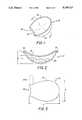
- FIG. 1is a perspective view of the preferred embodiment of the present invention illustrating two convex surfaces
- FIG. 2is a cross-sectional view of the hand padding device of FIG. 1 along centerline 2--2 of FIG. 1;
- FIG. 3is a top view of the hand padding device of FIG. 1, the dashed line illustrating an embodiment of the present invention which incorporates an extension of the enclosure for protecting the index finger;
- FIG. 4is a perspective view of another embodiment of the present invention illustrating a first substantially planar surface and the second convex surface;
- FIG. 5is a cross-sectional view of the hand padding device of FIG. 4 along centerline 5--5 of FIG. 4;
- FIG. 6is a top view of another embodiment of the present invention illustrating a configuration having a central, substantially circular area surrounded by a plurality of extensions;
- FIG. 7is a cross-sectional view of the hand padding device of FIG. 6 along line 7--7;
- FIG. 8is a perspective view of another embodiment of the present invention illustrating a substantially planar hand padding device.
- FIG. 9is a cross-sectional view of the hand padding device of FIG. 8 along line 9--9 of FIG. 8.
- FIGS. 1, 2, and 3illustrate the preferred embodiment of the present invention.
- Hand padding device 10is formed by joining pliable material 20 to pliable material 30 to form a generally cup-shaped enclosure which contains flowable material, the perimeter of which approximates the shape of a horseshoe.
- Pliable materials 20 and 30have either spherical surfaces (curved in more than one reference plane) or surfaces which are curved in at least one reference plane, the surfaces of pliable materials 20 and 30 being convexly shaped.
- the convexity of pliable materials 20 and 30offers a number of advantages. Initially, the preformed convexity of pliable material 20 allows padding device 10 to substantially conform to the curvature of each individual user's hand. Two elements, the preformed convexity and the general flexibility of hand padding device 10, work in combination to achieve this advantage. Substantial initial conformance of hand padding device 10 to the curvature of a hand is important in that more of the surface area of convexly shaped pliable material 20 will be in direct (if hand padding device 10 is placed in the hand) or indirect (if hand padding device 10 is inserted into a pocket or sleeve within a baseball glove) contact with the hand.
- hand padding device 10reduces the likelihood that hand padding device 10 will become displaced and not adequately protect the sensitive areas of the hand. Furthermore, reducing gaps between hand padding device 10 and the hand improves the overall force distribution on the hand and reduces the possibility of the enclosure "slapping" against the hand upon impact with a ball.
- a second advantage of the preformed convexity of hand padding device 10is that the curvature of pliable material 30 is designed to substantially approximate the curvature of a particular ball, for instance a baseball.
- the curvature of pliable material 30should exactly correspond to the curvature of the ball to maximize the area of hand padding device which contacts, directly or indirectly, the ball.
- the radius of curvature of pliable material 30is greater than that of the particular ball.
- the above-described interface of curved surfacesis desirable in a number of respects.
- the substantial preformed conformance of pliable material 30 to a ballincreases the surface area of hand padding device 10 which a ball will contact, thereby initially applying the impact forces over a larger area.
- the preformed convexity of pliable material 30reduces the number of creases which tend to develop when hand padding device 10 experiences an applied force. Creases create high stress concentrations in hand padding device 10 which may ultimately lead to rupture. Therefore, it is desirable to reduce the number of creases and thus the high stress concentrations to reduce the probability of hand padding device 10 rupturing in use.
- a third advantage of the preformed convexity of both primary surfaces of hand padding device 10relates to the prevention of "bottoming out.” Bottoming out is a condition which occurs when the flowable materials completely migrate from the area of impact to other regions, and thus the pad offers little or no protection in this area.
- hand padding device 10Another feature of hand padding device 10 is its general horseshoe shape, best illustrated in FIGS. 1 and 3, which allows hand padding device 10 to define the perimeter of the portion of the hand most in need of protection.
- Notch 40generally defines the shape of the portion of the hand from the base of the thumb to the base of the index finger.
- the remaining boundaries of hand padding device 10follow the base areas of the fingers, down the side of the hand, and along the base of the hand near the wrist back up to the portion of notch 40 at the base of the thumb. Therefore, hand padding device 10 substantially covers the highly sensitive areas at the base of the fingers, as well as the palm of the hand.
- Pliable materials 20 and 30 which form hand padding device 10define the above-desired horseshoe configuration.
- pliable materials 20 and 30will be of the same general shape, pliable material 20 must of course be of somewhat larger dimensions since both surfaces of hand padding device 10 are convexly shaped, pliable material 20 forming the inner convex surface.
- the actual dimensions of hand padding device 10will vary depending upon the general size of the hand to be protected. However, for an average-sized hand, the length of hand padding device 10 will range from about 75 millimeters to about 105 millimeters (illustrated as line A in FIG. 3) and the width from about 70 millimeters to about 100 millimeters (illustrated as line B in FIG. 3).
- the maximum thickness of the enclosurewill typically range from about 5 millimeters to about 15 millimeters in the central region (illustrated as line C in FIG. 3), and the depth of curvature (i.e., the distance from a substantially horizontal plane lying across convex surface 30 to the center of convex surface 20 as best illustrated by line D in FIG. 2) will typically range from about 15millimeters to about 20 millimeters.
- the volume of flowable material required to optimize performance of hand padding device 10will range from about 10 cm 3 to about 25 cm 3 .
- pliable materials 20 and 30are capable of containing the flowable material, that they exhibit a certain degree of flexibility, and that they possess a certain resistance to puncturing.
- Materials which are suitable for use in padding device 10include polyurethane or polyvinyl (e.g.
- polyvinylchloridematerials, acrylonitrile-butadiene-styrene (ABS) resins; acetals; acrylics; cellulosics; chlorinated polyethers; fluorocarbons, such as polytetrafluoroethylene (TFE), polychlorotrifluoroethylene (CTEE), and fluorinated ethylene propylene (FEP); nylons (polyamides); polycarbonates; polyethylenes (including copolymers); polybutylenes; polypropylenes; polystyrenes; polyesters; polysulfones; the preferred material being polyurethane.
- the thickness of pliable materials 20 and 30will typically range from about 0.01 millimeters to about 0.08 millimeters.
- the primary advantage of using a flowable materialis its ability to react to an applied force and actually migrate to other regions of the padding device to more effectively distribute impact forces over a larger area, the transfer of flowable materials also dissipating a portion of the energy transferred to the enclosure at impact. Therefore, the key limitation on the flowable material used in all embodiments of the present invention is that it possess fluid characteristics.
- Materialssuch as wax, glycerin, water, salt water, grease, fats, oils, propylene glycol, and syrup, with viscosities ranging from about 50 centipoise to about 200,000 centipoise, and preferably with viscosities ranging from about 1,000 centipoise to about 100,000 centipoise, can thus be used.
- the preferred flowable materialsare HB Fuller 1454 Hot MeltTM (a flowable microcrystalline wax) and glycerine because they are nontoxic and also will not harm the hand or the glove in the event of a rupture of the enclosure. Small, lightweight particles may also be included in the flowable material to reduce the overall density.
- pliable materials 20 and 30 as described aboveare affixed to each other, preferably by heat sealing or by using other methods known to those skilled in the art after convexity has been introduced to pliable materials 20 and 30 by vacuum forming.
- the resulting configurationis thus horseshoe-shaped to form an enclosure having convexly-shaped inner and outer surface.
- the seal between pliable materials 20 and 30is a substantially flat surface 25.
- a small openingis left in the enclosure for insertion of a filling apparatus (not shown) into the formed enclosure.
- the filling deviceis inserted into the opening and a predetermined volume of flowable material is placed therein.
- the filling deviceis removed and the opening in hand padding device 10 is sealed. It is typically unnecessary to remove air from the enclosure prior to sealing since the air will also act as a shock absorbing medium, but of course the additional step of removing air can also be performed so that only flowable material will occupy hand padding device 10.
- hand padding device 10is used in conjunction with a baseball or other glove which is subjected to concentrated forces generated by catching or contacting a ball.
- Hand padding device 10is either placed in the user's hand before the user actually puts on a baseball or other glove or is placed in a sleeve or pocket contained within the glove which is specifically designed to contain such a padding device.
- the ballexerts a force on the glove which is then transferred to certain areas of the convexly shaped pliable material 30.
- the area of indirect contact between pliable material 30 and the ballis increased because of the preformed convexity of pliable material 30.
- the convexity of pliable material 20, together with the general flexibility of padding device 10allows hand padding device 10 to substantially conform to the shape of the user's hand.
- the cumulative effect of substantial conformance of hand padding device 10 to the ball and the user's handresults in the distribution of the force over a larger area, which in effect reduces the stress introduced onto any one particular region of the hand.
- Hand padding device 10also absorbs a portion of the energy transferred at impact by the energy required to transfer flowable materials away from the point of the force application to other regions of hand padding device 10. Moreover, pliable material 30 will stretch and deform when experiencing an applied force which will also dissipate a portion of the energy transferred at impact.
- a second embodiment of the present inventionis hand padding device 50 as illustrated in FIGS. 4 and 5.
- Padding device 50is similar to hand padding device 10 of FIG. 1 in that it is produced by joining pliable material 60 to pliable material 70 to form a generally horseshoe-shaped enclosure which contains flowable materials, and thus the length and width dimension for hand padding device 10 apply to hand padding device 50.
- Pliable material 60like pliable material 20 in padding device 10, has a spherical surface or a surface which is curved in at least one reference plane, being convex in shape.
- the outer surface of padding device 50namely pliable material 70, is substantially planar in shape, possessing little or no curvature.
- the depth dimensions of hand padding device 50will differ from those identified for hand padding device 10.
- the maximum thickness at the central region of the enclosureillustrated by line E in FIG. 5, will range from about 15 millimeters to about 20 millimeters.
- the amount of flowable material required to optimize performance of hand padding device 50will range from about 10 cm 3 to about 35 cm 3 .
- hand padding device 50differs from that of hand padding device 10, the inner surface, pliable material 60, has a convexity similar to that of pliable material 20 in hand padding device 10. Therefore, all of the advantages of this convexity are present in hand padding device 50. Moreover, for ease of manufacturing, a flat seal 65 is formed when pliable material 60 and pliable material 70 are affixed to each other after the convexity has been introduced as was described in the process for forming hand padding device 10.
- hand padding device 50will suffer from a number of deficiencies not present in hand padding device 10. Specifically, since pliable material 70 is substantially planar, hand padding device 50 will be more likely to develop creases than will hand padding device 10. The creases introduce high stress concentrations which may eventually cause a rupture of hand padding device 50. In addition, the lack of a convex surface which is preformed in substantially the same shape as a ball will result in the forces being initially applied over a smaller area, and therefore will detract from the initial force distribution characteristics present in hand padding device 10. However, hand padding device 50 will still absorb and distribute impact forces more efficiently than known padding devices, as the method of absorbing and distributing impact forces will still be generally as was described for hand padding device 10.
- Hand padding device 90is produced by joining pliable material 100 to pliable material 110 to form a generally star or petal-shaped enclosure which contains flowable material.
- Pliable materials 100 and 110as can be seen in FIG. 7, are substantially planar, having little or no curvature.
- hand padding device 90does not have any preformed curvature, it is still able, based upon pliable materials 100 and 110 exhibiting flexibility characteristics similar to that of pliable materials 20 and 30 in hand padding device to substantially conform to the curvature of the user's hand. Therefore, the previously discussed benefits of substantially following the curvature of the hand apply generally to hand padding device 90. Moreover, when hand padding device 90 substantially conforms to the user's hand, there is a corresponding curvature which will substantially conform to the contour of a ball, resulting in hand padding device 90 possessing the advantages associated with this feature.
- Hand padding device 90is formed from pliable materials 100 and 110 which exhibit the same characteristics as pliable materials 20 and 30 of hand padding device 10.
- the outer contourwill be substantially circular with a diameter ranging from about 70 millimeters to about 110 millimeters.
- the inner region of hand padding device 90 defined by indentations 120is also substantially circular with a diameter ranging from about 35 millimeters to about 55 millimeters.
- Hand padding device 90typically will have a maximum thickness ranging from about 3 millimeters to about 20 millimeters. With this configuration the amount of flowable material required to optimize performance of hand padding device 90 will range from about 10 cm 3 to about 20 cm 3 .
- hand padding device 90lacks over hand padding device 10 is the preformed curvature, although hand padding device 90 conforms to a curved surface when inserted into a baseball glove.
- an advantage of the preformed curvaturessuch as those possessed by hand padding device 10 are a reduction of creases which form when a force is applied to hand padding device 90.
- hand padding device 90does not have preformed curvature, it is more likely than hand padding device 10 to develop creases, which may lead to the development of high stress concentrations which could result in the potential rupture of hand padding device 90.
- certain alterationshave been made to hand padding device 90 to reduce the development of such creases, namely by incorporating the star- or petal-shaped design as best illustrated in FIG. 6.
- the star or petal-shaped configuration of padding device 90is produced by introducing a number of slits into a substantially circular material and placing a seam around these slits to define an enclosure. Therefore, a plurality of finger-like extensions 130 and corresponding intentions 120 are produced. The use of these slits helps padding device 90 when it is cupped into the hand.
- hand padding device 90pliable materials 100 and 110 are cut into the above-described star- or petal-shaped configuration, filled with flowable material and sealed together as was described for hand padding device 10.
- the shaded regions of FIG. 6illustrate the region of the seal 135 between the materials which is substantially flat.
- Hand padding device 90then absorbs and distributes impact forces in a manner similar to that of hand padding device 10 since convexity, although not preformed, is obtainable due to the pliability of hand padding device 90 and its indentations 120.
- hand padding device 140is basically formed by joining pliable material 150 to pliable material 160 to form a generally circular shaped enclosure which contains flowable material.
- pliable materials 150 and 160are substantially planar, exhibiting little or no curvature in an undeformed condition.
- the outer diameter of hand padding device 140 and its maximum thicknesswill be similar to those dimensions identified for hand padding device 90.
- the volume of flowable material required to optimize performance of hand padding device 140will range from about 10 cm 3 to about 25 cm 3 .
- Hand padding device 140will behave similarly to hand padding device 90 in operation or use except that it lacks the means for reducing the stress concentrations produced by the development of creases in hand padding device 140. However, as was the case with hand padding device 90, hand padding device 140 is sufficiently flexible to conform to a curved surface, thereby resulting in padding device 140 possessing the advantages associated with these particular features.
- Extension 200can be added to each of the embodiments to provide protection to a substantial portion of the index finger. Extension 200 will be connected to the respective main embodiment and will thus contain flowable material to offer this protection.
Landscapes
- Health & Medical Sciences (AREA)
- General Health & Medical Sciences (AREA)
- Physical Education & Sports Medicine (AREA)
- Engineering & Computer Science (AREA)
- Textile Engineering (AREA)
- Professional, Industrial, Or Sporting Protective Garments (AREA)
- Gloves (AREA)
Abstract
Description
Claims (21)
Priority Applications (3)
| Application Number | Priority Date | Filing Date | Title |
|---|---|---|---|
| US07/537,055US5159717A (en) | 1988-10-14 | 1990-06-13 | Hand padding device |
| AU80015/91AAU8001591A (en) | 1990-06-13 | 1991-06-04 | Hand padding device |
| PCT/US1991/003931WO1991019425A1 (en) | 1990-06-13 | 1991-06-04 | Hand padding device |
Applications Claiming Priority (2)
| Application Number | Priority Date | Filing Date | Title |
|---|---|---|---|
| US75795588A | 1988-10-14 | 1988-10-14 | |
| US07/537,055US5159717A (en) | 1988-10-14 | 1990-06-13 | Hand padding device |
Related Parent Applications (1)
| Application Number | Title | Priority Date | Filing Date |
|---|---|---|---|
| US75795588AContinuation-In-Part | 1988-10-14 | 1988-10-14 |
Publications (1)
| Publication Number | Publication Date |
|---|---|
| US5159717Atrue US5159717A (en) | 1992-11-03 |
Family
ID=24140998
Family Applications (1)
| Application Number | Title | Priority Date | Filing Date |
|---|---|---|---|
| US07/537,055Expired - Fee RelatedUS5159717A (en) | 1988-10-14 | 1990-06-13 | Hand padding device |
Country Status (3)
| Country | Link |
|---|---|
| US (1) | US5159717A (en) |
| AU (1) | AU8001591A (en) |
| WO (1) | WO1991019425A1 (en) |
Cited By (21)
| Publication number | Priority date | Publication date | Assignee | Title |
|---|---|---|---|---|
| US5425142A (en)* | 1993-06-14 | 1995-06-20 | Scott; Daniel M. | Baseball glove having a gauge plate and an aromatic polyamide |
| US5632045A (en)* | 1995-05-08 | 1997-05-27 | Chase Ergonomics, Inc. | Antivibration glove |
| US5673437A (en)* | 1995-05-08 | 1997-10-07 | Chase Ergonomics Inc. | Vibration attenuating member and method of making same |
| US5711029A (en)* | 1996-06-21 | 1998-01-27 | Visco; Raymond D. | Protective apparatus for dispersing pressure applied at a joint |
| US5790980A (en)* | 1997-01-31 | 1998-08-11 | Yewer, Jr.; Edward H. | Padded glove |
| US5803416A (en)* | 1995-04-06 | 1998-09-08 | Alden Laboratories, Inc. | Hand, wrist and/or lower arm support pad and assemblies |
| US5815838A (en)* | 1997-03-13 | 1998-10-06 | Worth, Inc. | Sports glove |
| US5819312A (en)* | 1996-07-30 | 1998-10-13 | Snyder; Randy Bruce | Hand protection device |
| US5869164A (en) | 1995-11-08 | 1999-02-09 | Rik Medical Llc | Pressure-compensating compositions and pads made therefrom |
| US6292946B1 (en) | 2000-10-13 | 2001-09-25 | Michael Angione | Non-resilient insert for catching glove |
| US6494418B1 (en) | 1996-02-06 | 2002-12-17 | 3M Innovative Properties Company | Wrist rest assembly |
| US20030051316A1 (en)* | 2001-08-13 | 2003-03-20 | Willat Boyd I. | Deformable grip for a writing implement |
| US6723401B1 (en) | 1999-08-25 | 2004-04-20 | Ergodyne Corporation | Vibration damping member and method of making same |
| US20040126175A1 (en)* | 2002-10-02 | 2004-07-01 | Willat Boyd I. | Deformable grip with motion indicator |
| US20040217555A1 (en)* | 2000-01-15 | 2004-11-04 | Boyd Willat | Writing implement having deformable grip |
| US20060062628A1 (en)* | 2004-09-20 | 2006-03-23 | Ken Kostecki | Deformable grip for a writing implement |
| US20070017540A1 (en)* | 2005-06-21 | 2007-01-25 | Goody Products, Inc. | Handle Having a Ribbed Gel Grip |
| US20080173299A1 (en)* | 2007-01-19 | 2008-07-24 | Beth Bromberg | Breast self-exam device |
| US20100071108A1 (en)* | 2008-09-22 | 2010-03-25 | Nike, Inc. | Sports Glove With Impact Force Attenuation System |
| US20110016596A1 (en)* | 2009-07-22 | 2011-01-27 | Nike, Inc. | Ball Glove Incorporating A Force Attenuation System |
| US20110190883A1 (en)* | 2005-06-03 | 2011-08-04 | Medtronic Xomed, Inc. | Nasal valve treatment method & apparatus |
Citations (25)
| Publication number | Priority date | Publication date | Assignee | Title |
|---|---|---|---|---|
| US450717A (en)* | 1891-04-21 | Robert reach | ||
| US1797116A (en)* | 1928-10-02 | 1931-03-17 | Clifford A Barden | Stingproof baseball glove |
| US1974616A (en)* | 1932-10-31 | 1934-09-25 | Kenzie K Kirkham | Athletic glove or mitt construction |
| US2695999A (en)* | 1951-09-07 | 1954-12-07 | Arnold Katie | Hand shield |
| US3237319A (en)* | 1964-06-22 | 1966-03-01 | Hanson Alden Wade | Ski boots having a thixotropic material encircling the ankle portion thereof |
| US3402411A (en)* | 1966-01-12 | 1968-09-24 | Hanson Alden Wade | Process for making boots, sports equipment and hats |
| US3635849A (en)* | 1969-09-08 | 1972-01-18 | University Patents Inc | Polyisobutylene paraffin wax and oil blends |
| US3890648A (en)* | 1974-09-11 | 1975-06-24 | Robert Eugene Beal | Protective device for use by player of a hardball game, particularly baseball |
| US4038762A (en)* | 1976-03-02 | 1977-08-02 | Hanson Industries Inc. | Viscous, flowable, pressure-compensating fitting materials and their use, including their use in boots |
| US4051553A (en)* | 1976-12-14 | 1977-10-04 | Howard Arthur R | Hand protector |
| US4083127A (en)* | 1977-03-17 | 1978-04-11 | Hanson Industries Incorporated | Adjustable, pressure-compensating, custom fitting pads having predetermined amount of fitting material and their use in boots |
| US4089070A (en)* | 1977-03-09 | 1978-05-16 | Cherry Kenneth F | Conforming grip glove |
| US4108928A (en)* | 1976-03-02 | 1978-08-22 | Hanson Industries Inc. | Method of producing a viscous flowable pressure-compensating fitting composition from hollow thermoplastic microblends with the use of high frequency heating and dispensing the composition into a sealable, flexible, protective enclosure means |
| US4144658A (en)* | 1976-09-16 | 1979-03-20 | Hanson Industries Inc. | Viscous, flowable, pressure-compensating fitting materials and their use, including their use in boots |
| US4229546A (en)* | 1978-07-27 | 1980-10-21 | Hanson Industries Incorporated | Viscous, flowable, pressure-compensating fitting compositions having therein both glass and resinous microbeads |
| US4243754A (en)* | 1978-09-05 | 1981-01-06 | Hanson Industries Incorporated | Viscous, flowable, pressure-compensating fitting compositions |
| US4471538A (en)* | 1982-06-15 | 1984-09-18 | Pomeranz Mark L | Shock absorbing devices using rheopexic fluid |
| US4546495A (en)* | 1984-09-24 | 1985-10-15 | Castillo David D | Glove apparatus for weightlifting presses |
| US4617684A (en)* | 1981-09-16 | 1986-10-21 | Green Paul G | Protective palm-pad |
| US4624016A (en)* | 1984-09-26 | 1986-11-25 | Luevano Freddie D | Athletic glove with built-in cushioning |
| US4630318A (en)* | 1985-01-18 | 1986-12-23 | Trion Corporation | Baseball catching means |
| US4748690A (en)* | 1987-04-03 | 1988-06-07 | Webster Charles H | Protective glove for use in athletics |
| US4802669A (en)* | 1987-10-13 | 1989-02-07 | Birmingham Peter C | Baseball training device |
| US4945571A (en)* | 1988-09-26 | 1990-08-07 | In Motion, Inc. | Liquid-cushioned outerwear |
| US4952439A (en)* | 1988-10-14 | 1990-08-28 | Alden Laboratories | Padding device |
Family Cites Families (2)
| Publication number | Priority date | Publication date | Assignee | Title |
|---|---|---|---|---|
| US1083795A (en)* | 1912-12-13 | 1914-01-06 | James Isaac Brokaw | Hand-ball glove. |
| US2295999A (en)* | 1941-07-01 | 1942-09-15 | Michael J Mchale | Flier construction |
- 1990
- 1990-06-13USUS07/537,055patent/US5159717A/ennot_activeExpired - Fee Related
- 1991
- 1991-06-04WOPCT/US1991/003931patent/WO1991019425A1/enunknown
- 1991-06-04AUAU80015/91Apatent/AU8001591A/ennot_activeAbandoned
Patent Citations (25)
| Publication number | Priority date | Publication date | Assignee | Title |
|---|---|---|---|---|
| US450717A (en)* | 1891-04-21 | Robert reach | ||
| US1797116A (en)* | 1928-10-02 | 1931-03-17 | Clifford A Barden | Stingproof baseball glove |
| US1974616A (en)* | 1932-10-31 | 1934-09-25 | Kenzie K Kirkham | Athletic glove or mitt construction |
| US2695999A (en)* | 1951-09-07 | 1954-12-07 | Arnold Katie | Hand shield |
| US3237319A (en)* | 1964-06-22 | 1966-03-01 | Hanson Alden Wade | Ski boots having a thixotropic material encircling the ankle portion thereof |
| US3402411A (en)* | 1966-01-12 | 1968-09-24 | Hanson Alden Wade | Process for making boots, sports equipment and hats |
| US3635849A (en)* | 1969-09-08 | 1972-01-18 | University Patents Inc | Polyisobutylene paraffin wax and oil blends |
| US3890648A (en)* | 1974-09-11 | 1975-06-24 | Robert Eugene Beal | Protective device for use by player of a hardball game, particularly baseball |
| US4108928A (en)* | 1976-03-02 | 1978-08-22 | Hanson Industries Inc. | Method of producing a viscous flowable pressure-compensating fitting composition from hollow thermoplastic microblends with the use of high frequency heating and dispensing the composition into a sealable, flexible, protective enclosure means |
| US4038762A (en)* | 1976-03-02 | 1977-08-02 | Hanson Industries Inc. | Viscous, flowable, pressure-compensating fitting materials and their use, including their use in boots |
| US4144658A (en)* | 1976-09-16 | 1979-03-20 | Hanson Industries Inc. | Viscous, flowable, pressure-compensating fitting materials and their use, including their use in boots |
| US4051553A (en)* | 1976-12-14 | 1977-10-04 | Howard Arthur R | Hand protector |
| US4089070A (en)* | 1977-03-09 | 1978-05-16 | Cherry Kenneth F | Conforming grip glove |
| US4083127A (en)* | 1977-03-17 | 1978-04-11 | Hanson Industries Incorporated | Adjustable, pressure-compensating, custom fitting pads having predetermined amount of fitting material and their use in boots |
| US4229546A (en)* | 1978-07-27 | 1980-10-21 | Hanson Industries Incorporated | Viscous, flowable, pressure-compensating fitting compositions having therein both glass and resinous microbeads |
| US4243754A (en)* | 1978-09-05 | 1981-01-06 | Hanson Industries Incorporated | Viscous, flowable, pressure-compensating fitting compositions |
| US4617684A (en)* | 1981-09-16 | 1986-10-21 | Green Paul G | Protective palm-pad |
| US4471538A (en)* | 1982-06-15 | 1984-09-18 | Pomeranz Mark L | Shock absorbing devices using rheopexic fluid |
| US4546495A (en)* | 1984-09-24 | 1985-10-15 | Castillo David D | Glove apparatus for weightlifting presses |
| US4624016A (en)* | 1984-09-26 | 1986-11-25 | Luevano Freddie D | Athletic glove with built-in cushioning |
| US4630318A (en)* | 1985-01-18 | 1986-12-23 | Trion Corporation | Baseball catching means |
| US4748690A (en)* | 1987-04-03 | 1988-06-07 | Webster Charles H | Protective glove for use in athletics |
| US4802669A (en)* | 1987-10-13 | 1989-02-07 | Birmingham Peter C | Baseball training device |
| US4945571A (en)* | 1988-09-26 | 1990-08-07 | In Motion, Inc. | Liquid-cushioned outerwear |
| US4952439A (en)* | 1988-10-14 | 1990-08-28 | Alden Laboratories | Padding device |
Cited By (32)
| Publication number | Priority date | Publication date | Assignee | Title |
|---|---|---|---|---|
| US5425142A (en)* | 1993-06-14 | 1995-06-20 | Scott; Daniel M. | Baseball glove having a gauge plate and an aromatic polyamide |
| US6626403B1 (en) | 1994-06-03 | 2003-09-30 | 3M Innovative Properties Company | Wrist rest assembly |
| US6843454B2 (en) | 1994-06-03 | 2005-01-18 | 3M Innovative Properties Company | Method of assembling a wrist rest |
| US5803416A (en)* | 1995-04-06 | 1998-09-08 | Alden Laboratories, Inc. | Hand, wrist and/or lower arm support pad and assemblies |
| US5632045A (en)* | 1995-05-08 | 1997-05-27 | Chase Ergonomics, Inc. | Antivibration glove |
| US5673437A (en)* | 1995-05-08 | 1997-10-07 | Chase Ergonomics Inc. | Vibration attenuating member and method of making same |
| US5869164A (en) | 1995-11-08 | 1999-02-09 | Rik Medical Llc | Pressure-compensating compositions and pads made therefrom |
| US6494418B1 (en) | 1996-02-06 | 2002-12-17 | 3M Innovative Properties Company | Wrist rest assembly |
| US5711029A (en)* | 1996-06-21 | 1998-01-27 | Visco; Raymond D. | Protective apparatus for dispersing pressure applied at a joint |
| US5819312A (en)* | 1996-07-30 | 1998-10-13 | Snyder; Randy Bruce | Hand protection device |
| US5790980A (en)* | 1997-01-31 | 1998-08-11 | Yewer, Jr.; Edward H. | Padded glove |
| US5815838A (en)* | 1997-03-13 | 1998-10-06 | Worth, Inc. | Sports glove |
| US6723401B1 (en) | 1999-08-25 | 2004-04-20 | Ergodyne Corporation | Vibration damping member and method of making same |
| US20040217555A1 (en)* | 2000-01-15 | 2004-11-04 | Boyd Willat | Writing implement having deformable grip |
| US7334298B2 (en) | 2000-01-15 | 2008-02-26 | Sanford, L.P. | Writing implement having deformable grip |
| US6292946B1 (en) | 2000-10-13 | 2001-09-25 | Michael Angione | Non-resilient insert for catching glove |
| US20030051316A1 (en)* | 2001-08-13 | 2003-03-20 | Willat Boyd I. | Deformable grip for a writing implement |
| US20040126175A1 (en)* | 2002-10-02 | 2004-07-01 | Willat Boyd I. | Deformable grip with motion indicator |
| US6793426B2 (en) | 2002-10-02 | 2004-09-21 | Sanford L.P. | Deformable grip with motion indicator |
| US20060062628A1 (en)* | 2004-09-20 | 2006-03-23 | Ken Kostecki | Deformable grip for a writing implement |
| US10292812B2 (en)* | 2005-06-03 | 2019-05-21 | Medtronic Xomed, Inc. | Nasal valve treatment method and apparatus |
| US9925042B2 (en) | 2005-06-03 | 2018-03-27 | Medtronic Xomed, Inc. | Nasal valve treatment method and apparatus |
| US9358104B2 (en) | 2005-06-03 | 2016-06-07 | Medtronic Xomed, Inc. | Nasal valve treatment method and apparatus |
| US20110190883A1 (en)* | 2005-06-03 | 2011-08-04 | Medtronic Xomed, Inc. | Nasal valve treatment method & apparatus |
| US20070017540A1 (en)* | 2005-06-21 | 2007-01-25 | Goody Products, Inc. | Handle Having a Ribbed Gel Grip |
| US7797782B2 (en) | 2005-06-21 | 2010-09-21 | Goody Products, Inc. | Handle having a ribbed gel grip |
| US8006319B2 (en)* | 2007-01-19 | 2011-08-30 | Beth Bromberg | Breast self-exam device |
| US20080173299A1 (en)* | 2007-01-19 | 2008-07-24 | Beth Bromberg | Breast self-exam device |
| US8656513B2 (en)* | 2008-09-22 | 2014-02-25 | Nike, Inc. | Sports glove with impact force attenuation system |
| US20100071108A1 (en)* | 2008-09-22 | 2010-03-25 | Nike, Inc. | Sports Glove With Impact Force Attenuation System |
| US8220071B2 (en) | 2009-07-22 | 2012-07-17 | Nike, Inc. | Ball glove incorporating a force attenuation system |
| US20110016596A1 (en)* | 2009-07-22 | 2011-01-27 | Nike, Inc. | Ball Glove Incorporating A Force Attenuation System |
Also Published As
| Publication number | Publication date |
|---|---|
| WO1991019425A1 (en) | 1991-12-26 |
| AU8001591A (en) | 1992-01-07 |
Similar Documents
| Publication | Publication Date | Title |
|---|---|---|
| US5159717A (en) | Hand padding device | |
| US4064565A (en) | Helmet structure | |
| US5920915A (en) | Protective padding for sports gear | |
| US5131174A (en) | Self-reinitializing padding device | |
| US4422183A (en) | Protective body shield | |
| US6839910B2 (en) | Protective athletic equipment | |
| US6055676A (en) | Protective padding for sports gear | |
| US4985931A (en) | Shock absorbing pad structure for athletic equipment | |
| US7004655B2 (en) | Cushioning element | |
| US4642814A (en) | Athletic padding | |
| US4700403A (en) | Protective cushion | |
| US5398342A (en) | Air management baseball glove | |
| US6425141B1 (en) | Protective helmet | |
| US4513449A (en) | Shock absorbing athletic equipment | |
| US6098200A (en) | Padded glove for protecting and positioning the hand of a wearer | |
| US6131196A (en) | Air capsule cushion padding member for protective joint and safety pads | |
| US4193135A (en) | Protective device for the hand | |
| US6961960B2 (en) | High strength impact resistant hand protector | |
| US5083314A (en) | Sports glove | |
| US20160029724A1 (en) | Energy absorbing and displacing structure for body protective padding | |
| US5339465A (en) | Palm guard for sports | |
| US20120316485A1 (en) | Padded cycling glove that reduces nerve injury | |
| US20070163032A1 (en) | Cervical spine protection device | |
| US7895677B1 (en) | Chin guard with bumped contact surface | |
| GB2085708A (en) | Leg guard |
Legal Events
| Date | Code | Title | Description |
|---|---|---|---|
| AS | Assignment | Owner name:ALDEN LABORATORIES, INC., A COMPANY OF CO, COLORAD Free format text:ASSIGNMENT OF ASSIGNORS INTEREST.;ASSIGNORS:DREW, TERRENCE M.;HANSON, ALDEN B.;HANSON, CHRIS A.;REEL/FRAME:005332/0404 Effective date:19900612 | |
| AS | Assignment | Owner name:BANK ONE, BOULDER, N.A., COLORADO Free format text:SECURITY INTEREST;ASSIGNOR:ALDEN LABORATORIES, INC.;REEL/FRAME:006817/0004 Effective date:19930412 | |
| REMI | Maintenance fee reminder mailed | ||
| FPAY | Fee payment | Year of fee payment:4 | |
| SULP | Surcharge for late payment | ||
| AS | Assignment | Owner name:BANK ONE, COLORADO, N.A., COLORADO Free format text:SECURITY AGREEMENT;ASSIGNOR:ALDEN LABORATORIES, INC.;REEL/FRAME:008470/0201 Effective date:19961126 | |
| AS | Assignment | Owner name:ALDEN LABORATORIES, INC., COLORADO Free format text:SECURITY INTEREST RELEASE;ASSIGNOR:BANK ONE, COLORADO, N.A., FORMERLY KNOWN AS BANK ONE, BOULDER;REEL/FRAME:008345/0307 Effective date:19961120 | |
| AS | Assignment | Owner name:JAY, ERIC C., COLORADO Free format text:ABSTRACT OF SETTLEMENT AGREEMENT AND RELEASE;ASSIGNORS:ALDEN LABORATORIES, INC.;FLOFIT MEDICAL, LLC;PRESSURE RELIEF TECHNOLOGIES, INC.;AND OTHERS;REEL/FRAME:008677/0016 Effective date:19961119 Owner name:ALDEN LABORATORIES, INC., COLORADO Free format text:ABSTRACT OF SETTLEMENT AGREEMENT AND RELEASE;ASSIGNORS:ALDEN LABORATORIES, INC.;FLOFIT MEDICAL, LLC;PRESSURE RELIEF TECHNOLOGIES, INC.;AND OTHERS;REEL/FRAME:008677/0016 Effective date:19961119 Owner name:PRESSURE RELIEF TECHNOLOGIES, INC., COLORADO Free format text:ABSTRACT OF SETTLEMENT AGREEMENT AND RELEASE;ASSIGNORS:ALDEN LABORATORIES, INC.;FLOFIT MEDICAL, LLC;PRESSURE RELIEF TECHNOLOGIES, INC.;AND OTHERS;REEL/FRAME:008677/0016 Effective date:19961119 Owner name:RIK MEDICAL, LLC, COLORADO Free format text:ABSTRACT OF SETTLEMENT AGREEMENT AND RELEASE;ASSIGNORS:ALDEN LABORATORIES, INC.;FLOFIT MEDICAL, LLC;PRESSURE RELIEF TECHNOLOGIES, INC.;AND OTHERS;REEL/FRAME:008677/0016 Effective date:19961119 Owner name:HANSON, ALDEN B., COLORADO Free format text:ABSTRACT OF SETTLEMENT AGREEMENT AND RELEASE;ASSIGNORS:ALDEN LABORATORIES, INC.;FLOFIT MEDICAL, LLC;PRESSURE RELIEF TECHNOLOGIES, INC.;AND OTHERS;REEL/FRAME:008677/0016 Effective date:19961119 Owner name:HANSON, CHRIS A., COLORADO Free format text:ABSTRACT OF SETTLEMENT AGREEMENT AND RELEASE;ASSIGNORS:ALDEN LABORATORIES, INC.;FLOFIT MEDICAL, LLC;PRESSURE RELIEF TECHNOLOGIES, INC.;AND OTHERS;REEL/FRAME:008677/0016 Effective date:19961119 Owner name:FLOWFIT MEDICAL, LLC, COLORADO Free format text:ABSTRACT OF SETTLEMENT AGREEMENT AND RELEASE;ASSIGNORS:ALDEN LABORATORIES, INC.;FLOFIT MEDICAL, LLC;PRESSURE RELIEF TECHNOLOGIES, INC.;AND OTHERS;REEL/FRAME:008677/0016 Effective date:19961119 Owner name:QUICKIE DESIGNS INC., CALIFORNIA Free format text:ABSTRACT OF SETTLEMENT AGREEMENT AND RELEASE;ASSIGNORS:ALDEN LABORATORIES, INC.;FLOFIT MEDICAL, LLC;PRESSURE RELIEF TECHNOLOGIES, INC.;AND OTHERS;REEL/FRAME:008677/0016 Effective date:19961119 Owner name:JAY MEDICAL LTD., COLORADO Free format text:ABSTRACT OF SETTLEMENT AGREEMENT AND RELEASE;ASSIGNORS:ALDEN LABORATORIES, INC.;FLOFIT MEDICAL, LLC;PRESSURE RELIEF TECHNOLOGIES, INC.;AND OTHERS;REEL/FRAME:008677/0016 Effective date:19961119 Owner name:SUNRISE MEDICAL INC., CALIFORNIA Free format text:ABSTRACT OF SETTLEMENT AGREEMENT AND RELEASE;ASSIGNORS:ALDEN LABORATORIES, INC.;FLOFIT MEDICAL, LLC;PRESSURE RELIEF TECHNOLOGIES, INC.;AND OTHERS;REEL/FRAME:008677/0016 Effective date:19961119 | |
| REMI | Maintenance fee reminder mailed | ||
| LAPS | Lapse for failure to pay maintenance fees | ||
| FP | Lapsed due to failure to pay maintenance fee | Effective date:20001103 | |
| STCH | Information on status: patent discontinuation | Free format text:PATENT EXPIRED DUE TO NONPAYMENT OF MAINTENANCE FEES UNDER 37 CFR 1.362 |