US5159673A - Apparatus for networking programmable logic controllers to host computers - Google Patents
Apparatus for networking programmable logic controllers to host computersDownload PDFInfo
- Publication number
- US5159673A US5159673AUS07/850,234US85023492AUS5159673AUS 5159673 AUS5159673 AUS 5159673AUS 85023492 AUS85023492 AUS 85023492AUS 5159673 AUS5159673 AUS 5159673A
- Authority
- US
- United States
- Prior art keywords
- messages
- message
- user
- alarm
- host computer
- Prior art date
- Legal status (The legal status is an assumption and is not a legal conclusion. Google has not performed a legal analysis and makes no representation as to the accuracy of the status listed.)
- Expired - Lifetime
Links
- 230000006855networkingEffects0.000title1
- 238000004891communicationMethods0.000claimsabstractdescription88
- 230000015654memoryEffects0.000claimsdescription21
- 238000012546transferMethods0.000claimsdescription4
- 239000000872bufferSubstances0.000description26
- 230000005540biological transmissionEffects0.000description25
- 238000000034methodMethods0.000description17
- 230000004044responseEffects0.000description14
- 101100408352Drosophila melanogaster Plc21C geneProteins0.000description13
- 238000001514detection methodMethods0.000description4
- 238000010586diagramMethods0.000description3
- 230000006870functionEffects0.000description3
- 230000008569processEffects0.000description3
- 238000012545processingMethods0.000description3
- 238000010926purgeMethods0.000description3
- 102100036409Activated CDC42 kinase 1Human genes0.000description2
- 102100038192Serine/threonine-protein kinase TBK1Human genes0.000description2
- 230000003466anti-cipated effectEffects0.000description1
- 230000006399behaviorEffects0.000description1
- 230000008859changeEffects0.000description1
- 125000004122cyclic groupChemical group0.000description1
- 238000012217deletionMethods0.000description1
- 230000037430deletionEffects0.000description1
- 230000000694effectsEffects0.000description1
- 230000007246mechanismEffects0.000description1
- 238000007781pre-processingMethods0.000description1
- 238000012913prioritisationMethods0.000description1
- 230000007727signaling mechanismEffects0.000description1
Images


Classifications
- G—PHYSICS
- G05—CONTROLLING; REGULATING
- G05B—CONTROL OR REGULATING SYSTEMS IN GENERAL; FUNCTIONAL ELEMENTS OF SUCH SYSTEMS; MONITORING OR TESTING ARRANGEMENTS FOR SUCH SYSTEMS OR ELEMENTS
- G05B19/00—Programme-control systems
- G05B19/02—Programme-control systems electric
- G05B19/04—Programme control other than numerical control, i.e. in sequence controllers or logic controllers
- G05B19/05—Programmable logic controllers, e.g. simulating logic interconnections of signals according to ladder diagrams or function charts
- G05B19/052—Linking several PLC's
- H—ELECTRICITY
- H04—ELECTRIC COMMUNICATION TECHNIQUE
- H04L—TRANSMISSION OF DIGITAL INFORMATION, e.g. TELEGRAPHIC COMMUNICATION
- H04L51/00—User-to-user messaging in packet-switching networks, transmitted according to store-and-forward or real-time protocols, e.g. e-mail
- H04L51/21—Monitoring or handling of messages
- H04L51/212—Monitoring or handling of messages using filtering or selective blocking
- H—ELECTRICITY
- H04—ELECTRIC COMMUNICATION TECHNIQUE
- H04L—TRANSMISSION OF DIGITAL INFORMATION, e.g. TELEGRAPHIC COMMUNICATION
- H04L51/00—User-to-user messaging in packet-switching networks, transmitted according to store-and-forward or real-time protocols, e.g. e-mail
- H04L51/48—Message addressing, e.g. address format or anonymous messages, aliases
- H—ELECTRICITY
- H04—ELECTRIC COMMUNICATION TECHNIQUE
- H04L—TRANSMISSION OF DIGITAL INFORMATION, e.g. TELEGRAPHIC COMMUNICATION
- H04L9/00—Cryptographic mechanisms or cryptographic arrangements for secret or secure communications; Network security protocols
- H04L9/40—Network security protocols
Definitions
- PLCsprogrammable logic controllers
- a host computercan concurrently perform a plurality of applications programs, or user tasks.
- a PLCWhen a PLC is connected to such a host computer, it is often important for the host computer to obtain data from the PLC. Typically this is accomplished by having the host computer poll the PLC. However, this polling either requires the host computer to interrupt the PLC's processing of its ladder program, or it requires the host computer to wait for the PLC to complete a scan of its ladder program. Further it is often important for the PLC to send unsolicited information to the host computer.
- FIG. 1is a block diagram of a plurality of microprocessor based devices coupled to a high-speed communications network
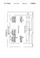
- FIG. 2is a more detailed block diagram illustrating software architecture of a host computer and a PLC, each coupled to the high-speed data communications network;
- FIG. 3is a software data flow diagram illustrating important elements in the communications architecture of the system.
- the communications network 23comprises a Thin Wire Ethernet (Type 10BASE2) 10Mbaud network.
- the host computer 25can couple directly to the Thin Wire Ethernet network with an appropriate Thin Wire Ethernet interface (not shown), or it can attach to a standard Ethernet (Type 10BASE5) network which is then connected through a repeater (not shown) to the Thin Wire Ethernet network.
- One such repeateris a DEC model DEMPR-AA multi-port repeater which has one 15-pin transceiver cable connector and eight Thin Wire connectors.
- Another repeateris a DEC model DESPR-AA single-port repeater, which has one 15-pin transceiver cable connector and one Thin Wire connector.
- the 15-pin transceiver cableis used to connect the repeaters to a standard thick-wire Ethernet.
- the DEMPR-AA and DESPR-AAcount as one Thin Wire network drop on each network to which they are attached, so up to 29 microprocessor based devices can be attached to each port.
- the repeatersdo not require drop numbers.
- the host computer 25further includes a global alarm queue 60. Specifics of the software architecture are discussed below with respect to FIG. 3.
- the task mailbox registers 61, 62, 63, and their respective alarm queues 64, 65, 66,are assigned the drop number of their respective device.
- the first user task mailbox register 61is located at drop number "6". Therefore, the first user task mailbox register 61 and the first user alarm queue, have the drop number "6".
- the user task mailbox registers 61, 62, 63have the same drop numbers as their respective user alarm queues 64, 65, 66.
- Data to be sent to one of the user task mailbox registers 61, 62, 63is distinguished from data to be sent to one of their respective user alarm queues 64, 65, 66, by the particular register address.
- Two locations in the first PLC 21are able to receive and store data, that being the mailbox register 39 and the image table 32.
- the number "5" of the routing address (5, 107)represents the location of the origination of the data, in this case being the device coupled to drop number "5".
- the number "107" of the routing address (5, 107)is the address of the global mailbox register 54.
- the ENIM mailbox registers of the individual PLCs on the communications network 23, such as the mailbox register 39 of the first PLC 21,are assigned an address number "200".
- the number "200"precedes the drop number of its respective drop location. For example, if data is to be transferred from the first user task 55, to the mailbox register 39, the routing would be (6, 7, 200, 5).
- the number "6" of the routing address (6, 7, 200, 5)indicates the location of the origination of the message, in this case being the drop number of the first user task 55.
- the number "7" of the routing address (6, 7, 200, 5)represents the exit from the software bus 67.
- the user task mailbox registers 61, 62, 63,are requested and specified when the respective user task first connects to the dispatcher 52.
- the host configuration table 72is a block of 1000 registers coupled to the second network module 71. As indicated above, the first network module 69 and second network module 71 emulate two back-to-back hardware NIMs. Therefore, as with the ENIM 35, the host configuration table 72 has an address of "200" followed by the drop number of its respective drop location, which in this case would be (200,7).
- the host configuration table 72specifies protocol data, such as response time-outs, retries and the like.
- Each of the user tasks 55, 57, 59can have up to 8192 user task registers numbered in the range 0001-8192.
- the particular mailbox register numbersare specified by its respective user task. Start and end register numbers of start and end registers can be anywhere in the range, if fewer than 8192 registers are needed. For example, 1000 mailbox registers could be numbered 1234-2233, if desired.
- Each of the tasks, user tasks as well as system taskincludes a respective per-process mailbox, such as the first per-process mailbox 80 associated with the first user task 55.
- the per-process mailbox 80is used as a signaling mechanism to inform the respective tasks that a message is available. Messages sent via the per-process mailbox 80 are simply a prompt; only a few bytes of pertinent data are actually transferred via the per-process mailbox 80. The actual message is placed into and temporarily stored in a communication buffer 82.
- the message buffers 96are memory locations for storing messages.
- the dispatcher input queue pointers 88identify locations in the message buffer 96 for messages received from the various ones of the tasks, user as well as system.
- the free list queue pointers 94identify unused (i.e., available) locations in the message buffer 96. Messages received from the communications network 23 are given a higher priority than messages from the tasks to lessen the chance of missing a message from the communications network 23.
- Messagesare similarly transferred from a task to the dispatcher 52. However because the dispatcher 52 does not distinguish between reply and command messages, only one queue is required.
- the particular user taskobtains an available message buffer from the free list queue pointers 94.
- an error replyis generated.
- the error replyis sent to the source of the command message.
- Unsolicited messagescan be accepted by the tasks, user as well as system. These messages can read and write data to the local mailboxes and write alarms to the local alarm queues
- the present inventionalso provides for prioritization and response to alarms by the host computer 25, both on a global level as well as on a user task level.
- Alarms on the global levelare accessible by any one of the user tasks 55, 57, 59, while alarms on the user task level are only accessible by that particular one of the user tasks 55, 57, 59.
- An alarmis written to an alarm queue, by another device, by issuing a write-register command to the particular register, based on the queue to be written.
- these "pointer" registersare:
- the dispatcher 52further includes a configuration file 52c comprising a disk file that the dispatcher 52 reads when it starts running to determine a number of operating parameters, such as the drop number of the host computer 25.
- a configuration file 52ccomprising a disk file that the dispatcher 52 reads when it starts running to determine a number of operating parameters, such as the drop number of the host computer 25.
- the drop number of the global alarm queuesis the drop number of the host computer 25 plus 100. Therefore, the route of an alarm write operation would have the drop number of the host computer 25 plus 100 as the last route number.
- Each of the user tasks 55, 57, 59has an option of setting up three alarm queues for itself. This is done when the particular one of the user tasks first "connects" to the dispatcher 52. These local alarm queues can only be read by the particular one of the user tasks; however alarms can be sent to the local alarm queues from anywhere on the system.
- the user task's drop numberwhich is also specified when the user task connects to the system task 53, is used as the last route number in the route field address of an alarm write operation.
- the second--last route numberis the drop number of the host computer 25.
- This communication protocolis used by any of the processor based devices on the communications network 23, including the host computer 25, that wish to exchange information.
- a timerdetermines if the sending device waited long enough for an acknowledgment (ACK) to be returned. The length of time that the sending device waits is user determinable.
- the GET ADDRESS REQUESTis only used to establish the addresses of the devices on the communications network 23.
- the GET ADDRESS REQUESTdoes not contain any data destined for an end device or task. Once the addresses of the devices on the communications network 23 are established, data can be sent to the end devices or tasks.
- the Ethernet transmit queueis reexamined to see if there are any other messages for this device. If other messages exist, the transmitter will perform steps 1-3 on new messages (without waiting for an acknowledgment of the original message). The only exception to this step is if there are 254 outstanding messages to a particular device. For this case, the transmitter will be required to hold any new message until an acknowledgement is received to a previous message.
Landscapes
- Engineering & Computer Science (AREA)
- Computer Security & Cryptography (AREA)
- Computer Networks & Wireless Communication (AREA)
- Signal Processing (AREA)
- Physics & Mathematics (AREA)
- General Physics & Mathematics (AREA)
- Automation & Control Theory (AREA)
- Computer And Data Communications (AREA)
Abstract
Description
This application is a continuation of application Ser. No. 07/497,465, filed Mar. 22, 1990, now abandoned.
1. Field of the Invention
Applicants' invention relates to microprocessor based devices and, more particularly, to a system to permit data sharing between microprocessor based devices and host computers on a high speed data communication network such as Ethernet.
2. Related Applications
This application is related to the following commonly assigned co-pending applications, all filed on Mar. 22, 1990; U.S. application Ser. No. 07/497,451, "an Equivalent Network Interface Module for Connecting a Programmable Logic Controller to a High Speed Communications Network"; U.S. application Ser. No. 07/496,461, "A System for Sharing Data Between Microprocessor Based Devices"; now U.S. Pat. No. 4,993,999, U.S. application Ser. No. 07/500,323, "A System for Processing Alarm Notifications in Microprocessor Based Devices"; U.S. patent application Ser. No. 07/497,455, "Emulation of a Programmable Logic Controller by a Host Computer.
3. Background Prior Art
As industrial automation advances, interconnectivity between various microprocessor based plant floor devices, such as programmable logic controllers ("PLCs"), and plant computers, becomes more and more desirable. For example, the extensive math and register commands of a PLC can perform data pre-processing on raw data right at the raw data's point of origin, as opposed to uploading all of the raw data to the host computer, thereby permitting use of a smaller host computer.
Various schemes have been developed to interconnect PLCs and host computers, but their applications have been limited. For example, if one wanted to communicatively couple three PLCs in the absence of a network, each PLC would typically require a separate serial, or point to point, connection with each of the other two PLCs. However, the speed of serial communication is limited. Further, as the number of interconnected PLCs grows linearly, the number of serial connections grows geometrically.
In a commonly assigned co-pending patent application, Ser. No. 180,093, a peer-to peer system is disclosed for interconnecting a plurality of PLCs. However this system requires a dedicated communication network.
Allen-Bradley Company, Inc., in conjunction with Digital Equipment Corporation ("DEC") has developed a system marketed under the trade name "Pyramid Integrator" for interconnecting devices over the relatively standardized Ethernet network via DEC's VAX® computer. However according to this system, only a maximum of four PLCs can be coupled to an Ethernet network per VAX computer, and each of the PLCs must be plugged into the backplane of the VAX computer. If five PLCs are required on the Ethernet, two VAX computers are required. This greatly adds to the expense of automation.
In addition, a host computer can concurrently perform a plurality of applications programs, or user tasks. When a PLC is connected to such a host computer, it is often important for the host computer to obtain data from the PLC. Typically this is accomplished by having the host computer poll the PLC. However, this polling either requires the host computer to interrupt the PLC's processing of its ladder program, or it requires the host computer to wait for the PLC to complete a scan of its ladder program. Further it is often important for the PLC to send unsolicited information to the host computer.
Messages typically are transmitted between microprocessor based devices on an Ethernet network in the form of data packets. The data packets generally include a preamble portion comprising routing information and protocol type, a user defined portion comprising the message itself, and an error detection portion. As the speed of communication between microprocessor based devices increases, error detection operations become ever more critical. Typically the error detection operation views the entire data packet to determine existence of an error. This often does not quickly enough detect errors in the user data portion. Further, the protocol often cannot accurately respond to lost messages.
Finally as automated systems control ever larger operations, handling and prioritizing of event notifications or alarms, such as faults, alerts and warnings, by the host computer becomes even more important. While certain host computers have been able to receive alarms, they have been received on a global basis, rather than individually on a user task basis.
Applicants' invention is provided to solve these and other problems.
It is an object of the invention to provide an apparatus for interconnecting PLCs and other microprocessor based devices over a high speed communications network, such as Ethernet.
It is a further object of the invention to provide a system wherein a host computer can immediately obtain data from a PLC without interrupting execution of the PLC's ladder program and wherein the host computer can receive unsolicited information from the PLC.
It is a still further object of the invention to provide a communication protocol including high speed error detection of the user data portion of a data packet.
It is yet another object of the invention to provide a communication protocol which can accurately respond to lost messages.
Finally, it is an object of the invention to provide a system which prioritizes alarms, such as faults, alerts and warnings, while also allowing for an essentially unlimited number of alarms per queue.
Other features and advantages of the invention will be apparent from the following specification taken in conjunction with the following drawings.
FIG. 1 is a block diagram of a plurality of microprocessor based devices coupled to a high-speed communications network;
FIG. 2 is a more detailed block diagram illustrating software architecture of a host computer and a PLC, each coupled to the high-speed data communications network;
FIG. 3 is a software data flow diagram illustrating important elements in the communications architecture of the system; and
FIG. 4 is a graphic illustration of the communication buffer of FIG. 3.
While this invention is susceptible of embodiments in many different forms, there is shown in the drawings and will herein be described in detail, a preferred embodiment of the invention with the understanding that the present disclosure is to be considered as an exemplification of the principles of the invention and is not intended to limit the broad aspects of the invention to the particular embodiment illustrated.
A first programmable logic controller ("PLC") 21 coupled to a high-speeddata communications network 23 is illustrated in FIG. 1. Other microprocessor based devices such as ahost computer 25 or other microprocessor baseddevices communications network 23. Thehost computer 25 can be a VAX® computer, sold by the Digital Equipment Corporation, and the PLC 21 can be a SY/MAX® Model 650 programmable controller, sold by Square D Company, assignee of this patent application.
Thecommunications network 23 comprises a Thin Wire Ethernet (Type 10BASE2) 10Mbaud network. Thehost computer 25 can couple directly to the Thin Wire Ethernet network with an appropriate Thin Wire Ethernet interface (not shown), or it can attach to a standard Ethernet (Type 10BASE5) network which is then connected through a repeater (not shown) to the Thin Wire Ethernet network.
Up to 100 microprocessor based devices can be connected to thecommunications network 23. A standard Thin Wire Ethernet network may have up to 30 devices attached. If a multi-port Thin Wire repeater is used, however, each of the repeater ports can have a 29-device network attached. All the Thin Wire and standard Ethernet networks connected through the repeater are logically part of the same network, therefore drop numbers (discussed below) used must be unique across the whole network. This is how up to 100 microprocessor based devices can be connected to the onecommunications network 23.
One such repeater is a DEC model DEMPR-AA multi-port repeater which has one 15-pin transceiver cable connector and eight Thin Wire connectors. Another repeater is a DEC model DESPR-AA single-port repeater, which has one 15-pin transceiver cable connector and one Thin Wire connector. The 15-pin transceiver cable is used to connect the repeaters to a standard thick-wire Ethernet. The DEMPR-AA and DESPR-AA count as one Thin Wire network drop on each network to which they are attached, so up to 29 microprocessor based devices can be attached to each port. The repeaters do not require drop numbers.
Thefirst PLC 21 includes a control processor 31 (Motorola 68010), an image table 32 and a scan processor 33 (AMD 29116). Traditionally PLCs have required a separate network interface module (or "NIM") in order to communicate on a high-speed communications network such as Ethernet. In accordance with one aspect of the invention, thefirst PLC 21 includes an equivalent network interface module (ENIM) 35. TheENIM 35 comprises a communications processor 37 (Motorola 68010) and random access memory operable as anENIM mailbox register 39. As discussed below, theENIM 35 is coupled to thecommunications network 23 via afirst port 35a.
A two-port RAM 41 has first andsecond ports first port 43 is coupled to theENIM 35. Thesecond port 45 is coupled to a data bus 47. The data bus 47 is also coupled to thecontrol processor 31, the image table 32 and thescan processor 33. Thecontrol processor 31 accesses the two-port RAM 41 via the data bus 47. Thecontrol processor 31 transfers data from the two-port RAM 41 to the image table 32, which is accessed by thescan processor 33. Thus, theENIM 35 and thecontrol processor 31 exchange data via the two-port RAM 41.
The mailbox register 39 provides random access registers to permit thefirst PLC 21 to receive unsolicited messages from other devices coupled to thecommunication network 23 without affecting operation of thescan processor 33. Unsolicited messages can also be received directly in the image table 32, but this requires interruption of thescan processor 33. Typically messages are first placed directly into theENIM mailbox register 39 and then are moved into the image table 32 at predetermined times by thescan processor 33. Only critical unsolicited messages, such as a stop bit to stop thescan processor 33, are placed directly into the image table 32.
Software architecture of thehost computer 25 as viewed by a user is illustrated in FIG. 2.
As indicated above, traditionally a PLC required a network interface module (NIM) to communicate over a high-speed data communications network. Such a NIM typically had only a single high-speed port, adaptable to communicatively couple to the network, and a serial port. Thus, in order to communicate between two networks, two separate NIMs were required so that each of the two high-speed ports could be coupled to a respective one of the networks. The two NIMs would then be jointly coupled by their serial ports. According to the invention, thehost computer 25 is provided with software architecture including a network to network (net-to-net) software bridge which permits PLCs and other similar devices coupled to thecommunications network 23 to communicate directly with user tasks within thehost computer 25 as though the user tasks were simply other PLC's on thecommunications network 23. Accordingly, such other PLC's are able to request data from the user tasks while the user tasks are running.
As discussed above, host computers have been able to poll specific PLCs coupled thereto for information, though such polling has required either interruption of the PLC's scan cycle, or waiting for completion of the PLC's scan cycle. However, these traditional host computers have been unable to obtain unsolicited messages from a PLC. Further, a host computer typically concurrently runs a plurality of user tasks. Sometimes it is desirable for unsolicited information from a PLC to be available for all of these concurrently running user tasks. At other times, it is desirable that the unsolicited information be available for only one, or a limited number, of these concurrently running user tasks.
Accordingly, thehost computer 25 illustrated in FIG. 2 operatively includes software architecture comprising a dispatcher (or software bridge) 52, asystem task 53, systemtask operating memory 53a, aglobal mailbox register 54, and first, second andthird user tasks user tasks dispatcher 52 accepts and routes data transfers between theuser tasks system task 53 and other devices on thecommunications network 23. Thedispatcher 52 thus acts as an intermediary between the system anduser tasks communications network 23 in a manner transparent to the system anduser tasks
Thehost computer 25 further includes aglobal alarm queue 60. Specifics of the software architecture are discussed below with respect to FIG. 3.
As viewed in FIG. 2, each of the first, second and third user tasks, 55, 57 and 59 includes respective first, second and third usertask operating memory 55a, 57a, 59a, wherein operating data is stored, as is well known. Each of the first, second and third user tasks, 55, 57 and 59 further includes respective first, second and third user task mailbox registers 61, 62, 63, and a respective first, second, andthird alarm queue third user tasks dispatcher 52 by a software bus 67. Thedispatcher 52 is a server program and includes first andsecond network modules second network modules communications network 23 and the software bus 67. Specifically, thefirst network module 69 andsecond network module 71 emulate two back-to-back hardware NIMs which traditionally, as described above, had been used to interconnect two networks. The first andsecond modules network 23 to communicate with selected ones of theuser tasks
Devices on thecommunications network 23 are operatively located at "drops". In order to route a message from one device to another, a routing address is added to the message indicating where the message is from (originating drop number), where the message is going (destination drop number) and the path for the message to get there (routing drop number). For example, thefirst PLC 21 is located on thecommunications network 23 at a drop "5", and thehost computer 25 is located on thecommunications network 23 at a drop "7". Thefirst user task 55 is located at a drop "6", thesecond user task 57 is located at a drop "8", and thethird user task 59 is located at a drop "9". Theglobal mailbox register 54 and theglobal alarm queue 60 are assigned a drop number of 100 plus the drop number of thecomputer 25, in this case being "107". Theglobal mailbox register 54 and theglobal alarm queue 60 have the same drop number. Data to be sent to theglobal mailbox register 39 is distinguished from data to be sent to theglobal alarm queue 60 by the particular register address.
The task mailbox registers 61, 62, 63, and theirrespective alarm queues task mailbox register 61 and the first user alarm queue, have the drop number "6". As with theglobal mailbox register 54 and theglobal alarm queue 60, the user task mailbox registers 61, 62, 63 have the same drop numbers as their respectiveuser alarm queues user alarm queues
Two locations in thefirst PLC 21 are able to receive and store data, that being themailbox register 39 and the image table 32. In order to route information from the two-port RAM 41 to theglobal mailbox register 54, one uses the routing address (5, 107). The number "5" of the routing address (5, 107) represents the location of the origination of the data, in this case being the device coupled to drop number "5". The number "107" of the routing address (5, 107) is the address of theglobal mailbox register 54.
The ENIM mailbox registers of the individual PLCs on thecommunications network 23, such as the mailbox register 39 of thefirst PLC 21, are assigned an address number "200". When routing data to a particular ENIM mailbox register, such as themailbox register 39, the number "200" precedes the drop number of its respective drop location. For example, if data is to be transferred from thefirst user task 55, to themailbox register 39, the routing would be (6, 7, 200, 5). The number "6" of the routing address (6, 7, 200, 5) indicates the location of the origination of the message, in this case being the drop number of thefirst user task 55. The number "7" of the routing address (6, 7, 200, 5) represents the exit from the software bus 67. The number "200" of the routing address (6, 7, 200, 5) indicates that the data is going to a PLC mailbox register, and the number "5" of the routing address (6, 7, 200, 5) indicates that it is the PLC mailbox register of the PLC coupled to drop number "5".
If unsolicited register data is to be available for each of theuser tasks global mailbox register 54. However, if the unsolicited register data is only for one of the user tasks, such as thefirst user task 55, the message is directed to the first usertask mailbox register 61. Similarly, if the message is for a selected, limited number, though not all, of the user tasks, the unsolicited register data would be sent to the mailbox registers of the selected, limited number of the user tasks. Similarly, thefirst PLC 21 or other similar devices on thecommunications network 23 can also obtain data from the individual user task mailbox registers 61, 63, 65, or theglobal mailbox register 54. Software resident in thehost computer 25 supports the user task mailbox registers 61, 62, 63 and theglobal mailbox register 54.
The user task mailbox registers 61, 62, 63, are requested and specified when the respective user task first connects to thedispatcher 52. The host configuration table 72 is a block of 1000 registers coupled to thesecond network module 71. As indicated above, thefirst network module 69 andsecond network module 71 emulate two back-to-back hardware NIMs. Therefore, as with theENIM 35, the host configuration table 72 has an address of "200" followed by the drop number of its respective drop location, which in this case would be (200,7). The host configuration table 72 specifies protocol data, such as response time-outs, retries and the like.
Measures such as slave response timeouts, reply timeouts and message retries are utilized to limit the inherently non-deterministic nature of the Ethernet network. These measures allow a user to specify a maximum time to wait for a message to be delivered, or a reply to be received, without error, effectively providing deterministic behavior on the network.
Each of theuser tasks user tasks respective alarm queues user tasks
Each of theuser tasks respective mailbox register
Indexing into an array is the most efficient way, as it is the user task's own mailbox register which is being read. Accordingly, the particular one of theuser tasks host computer 25. These specified memory blocks are used as mailbox registers, and the particular user task can access the specified memory blocks as an array of 16-bit register values. In the example above (mailbox registers 1234-2233), the user task reads mailbox register 1235 by reading the second word of the register array (memory block).
The second way of accessing a user task's own mailbox register is similar to reading any other mailbox register in that a read/write register command (a command by a user task to read or write to a particular register) is utilized. This is less efficient than the first way of a user task accessing its own mailbox register, discussed immediately above, as read or write subroutines must first be called. With read/write register commands, an empty route field of a register command (the terminator is the first entry) indicates that reads and writes will refer to the user task's own mailbox registers.
A 2-drop route field in a register command is used to read and write to other task's local mailboxes. A 3-drop route field is used to read theglobal mailbox 54; the middle number of the 3-drop route field being the drop number of thehost computer 25 and the last number of the 3-drop route field being the number "100" plus the drop number of thehost computer 25.
The actual software architecture is illustrated in the data flow chart of FIG. 3. Thesystem task 53 architecturally appears simply as another one of the user tasks, thus the following discussion with respect to thefirst user task 55 applies as well to thesystem task 53. Reference numbers common to FIG. 2 have been maintained.
Messages from one of theuser tasks user tasks communications network 23 or thesystem task 53 are routed through thedispatcher 52, as follows.
Each of the tasks, user tasks as well as system task, includes a respective per-process mailbox, such as the first per-process mailbox 80 associated with thefirst user task 55. The per-process mailbox 80 is used as a signaling mechanism to inform the respective tasks that a message is available. Messages sent via the per-process mailbox 80 are simply a prompt; only a few bytes of pertinent data are actually transferred via the per-process mailbox 80. The actual message is placed into and temporarily stored in acommunication buffer 82.
Thecommunication buffer 82 performs the function of the software bus 67 (FIG. 2) and is illustrated in FIG. 4. Thecommunication buffer 82 is part of the virtual memory RAM of thehost computer 25, which is allocated by the software of thehost computer 25 under control of thedispatcher 52. Thecommunication buffer 82 includes reply input queue pointers and command input queue pointers for each of the tasks, user as well as system, such as the first replyinput queue pointers 84 and the first commandinput queue pointers 86 which are associated with thefirst user task 55. The commandinput queue pointer 86 stores memory addresses of command messages directed toward theuser task 55, and the replyinput queue pointer 84 stores memory addresses of reply messages directed toward theuser task 55. The respective reply input queue pointers and command input queue pointers operate similarly for their respective tasks. Reply messages have a higher priority than command messages, therefore thecommunications buffer 82 distinguishes reply messages from command messages so that reply messages can be processed first.
Thecommunications buffer 82 further includes dispatcher queues, specifically dispatcher input queue pointers 88 and freelist queue pointers 94. Additionally, thecommunication buffer 82 includes message buffers 96.
The message buffers 96 are memory locations for storing messages. The dispatcher input queue pointers 88 identify locations in themessage buffer 96 for messages received from the various ones of the tasks, user as well as system. The freelist queue pointers 94 identify unused (i.e., available) locations in themessage buffer 96. Messages received from thecommunications network 23 are given a higher priority than messages from the tasks to lessen the chance of missing a message from thecommunications network 23.
Referring again to FIG. 3, the per-process mailbox 80 is simply a VMS (VAX software) mechanism for sending a prompt, indicating that a message is waiting. Data in one of the per-process mailbox interrupts the particular one of the tasks associated with the one of the per-process mailboxes, causing the particular one of the tasks to read the message, command or reply, located at the address stored in its respective reply and/or command input queue pointers in thecommunications buffer 82.
Messages are similarly transferred from a task to thedispatcher 52. However because thedispatcher 52 does not distinguish between reply and command messages, only one queue is required.
To send a command message from one of the user tasks, the particular user task obtains an available message buffer from the freelist queue pointers 94.
To send a reply message from one of the user tasks, the particular user task uses the same buffer which the command message was delivered in. In this way there will never be the situation where there are no free buffers to accept the reply message.
The particular one of the user tasks then writes the message data into the message buffer, and queues the message on the dispatcher input queue pointer 88. If the dispatcher input queue pointer was empty, a prompt is sent to a dispatcher prompt mailbox 98 to indicate a presence of a new message. Thedispatcher 52 will process the messages identified in the dispatcher input queue pointer until none are left.
For messages to be transferred from thedispatcher 52 to the communications network 23 (i.e. outbound Ethernet messages), thedispatcher 52 passes the address of the message to anEthernet driver 97. Thedispatcher 52 includes a pendingoutbound message pointer 52a and an inboundmessage queue pointer 52b. The pending outboundmessages queue pointer 52a identifies message buffer locations for messages to be transmitted on thecommunications network 23. The inboundmessage queue pointer 52b identifies message buffer locations for messages to be transferred from thedispatcher 52 to one of the tasks, user as well as system.
Thehost computer 25 must be able to reliably deliver messages. Messages may not be dropped except for extraordinary circumstances.
When a command message must be delivered to thefirst user task 55, thedispatcher 52 will queue the command message to the commandinput queue pointer 86. If the commandinput queue pointer 86 is empty, a message prompt will be sent to the first user task's 55 per-process mailbox 80. If the first user task's commandinput queue pointer 86 is not full, the message is queued, and no prompt is sent.
If the particular task specified by the routing address is not connected to thedispatcher 52, an error reply is generated. The error reply is sent to the source of the command message.
One does not want to overwhelm a particular task with commands such that the particular task cannot respond to commands as quickly as they are received, as this conceivably could result in filling all of the available communication buffers, which could then also back-up other ones of the tasks. Although this has not been found to be a problem in practice, it is contemplated that an error command could be generated if such did occur.
Unsolicited messages can be accepted by the tasks, user as well as system. These messages can read and write data to the local mailboxes and write alarms to the local alarm queues
Mailbox registers and alarm queues (both local and global) can also be used to implement data sharing between application programs. However, tasks will only respond to alarms, and read/write of the task mailbox registers. Other functions will result in error replies being returned to the sender.
The present invention also provides for prioritization and response to alarms by thehost computer 25, both on a global level as well as on a user task level. Alarms on the global level are accessible by any one of theuser tasks user tasks
As discussed above, thedispatcher 52 is provided with aglobal alarm queue 60. Theglobal alarm queue 60 has three levels of alarm sub-queues, specifically a globalfault alarm queue 60a for storing global fault alarms, a globalalert alarm queue 60b for storing global alert alarms and a globalwarning alarm queue 60c for storing global warning alarms.
In addition, each of the first, second and thirduser alarm queues
An alarm queue entry, whether global or user-level, contains the following information:
1. a reference number
2. a time-stamp indicating the time the alarm was received by thehost computer 25;
3. a routing address (the route from originator to destination);
4. level of alarm (i.e. fault alarms, alert alarms and warning alarms);
5. a user specified alarm code; and
6. user specified data.
The allowed number of alarms per queue and the number of user data registers is determined by the user, depending upon an anticipated number of alarms as well as available memory. Each of theuser tasks
1. Read first alarm--get alarm data for lst (i.e., oldest) alarm
2. Read specific alarm--get alarm data for an alarm, specified by the reference number of a particular alarm;
3. Read next alarm--get alarm data for the alarm with a reference number greater than (i.e., newer than) a reference number specified;
4. Clear alarm--delete an alarm from a queue;
5. Clear and acknowledge alarm--acknowledge and delete an alarm from a queue;
6. Clear all alarms--delete all alarms from a queue;
7. Clear and acknowledge all alarms--acknowledge and delete all alarms from a queue;
8. Set alarm notify--set up for task notification on addition/deletion of an alarm to/from a queue; and
9. Read alarm queue information--get information about an alarm queue.
As previously indicated, there are three types (levels) of alarm sub-queues: fault queues; alert queues; and warning queues. In general, the severity of an alarm condition dictates which alarm subqueue the alarm is posted to, with fault alarms being the most severe and warning alarms being the least severe.
An alarm is written to an alarm queue, by another device, by issuing a write-register command to the particular register, based on the queue to be written. In the present embodiment, these "pointer" registers are:
1. register number "8101" for a fault alarm;
2. register number "8102" for an alert alarm; and
3. register number "8103" for a warning alarm.
Thus, a fault alarm to be sent by thePLC 21 at drop number "5" to the first usertask alarm queue 64 would have the routing address (5, 7, 6) and would be written to register number 8101.
Generally, an alarm acknowledgement is sent back to the same register, in the device issuing the alarm, as the queue to which the alarm was written, though this can be overridden if the user desires to send an acknowledgement to a different register.
The first register value in the data field of an alarm write-register is an alarm code to be posted, and the remaining register values are support data for the alarm. The amount of support data for a particular alarm is controlled by the user's application and needs and can range from 0 to a user-specified number of registers, up to a maximum of 127 registers. A complete alarm write-register command, such as from thePLC 21, would contain:
1. a routing address from the device sending the alarm to the alarm queue location;
2. an alarm "opcode" indicating an alarm operation to be performed;
3. the sending device's status register address, which does not effect the alarm writing process;
4. the alarm queue register address (8101, 8102, or 8103) as the destination of the write register;
5. the alarm code for the particular alarm; and
6. any support data particularly desired by the user (0 or more user specified registers).
Thedispatcher 52 further includes aconfiguration file 52c comprising a disk file that thedispatcher 52 reads when it starts running to determine a number of operating parameters, such as the drop number of thehost computer 25. As indicated above, the drop number of the global alarm queues is the drop number of thehost computer 25 plus 100. Therefore, the route of an alarm write operation would have the drop number of thehost computer 25 plus 100 as the last route number.
Each alarm queue entry is time-stamped with the current time of thehost computer 25 when it is written to an alarm queue. Additionally, each alarm queue entry is given a unique reference number for identification. If an attempt is made to write an alarm to an alarm queue that is already full, a standard error code, such as "alarm buffer full", is returned in a priority-write reply message.
The threeglobal alarm queues system task 53 is initially started up, usually upon system boot. The length (number of entries) and width (maximum number of support data registers) of these alarm queues are specified in theconfiguration file 52c and can be modified only by shutting down thedispatcher 52, modifying theconfiguration file 52c, and restarting thedispatcher 52, such as by re-booting the system. If the length of the global alarm queues is specified as 0, no global alarm queues are created.
Any external device or internal task can write to the global alarm queues, and any internal task can view, clear, and acknowledge alarms from the global alarm queues.
Each of theuser tasks dispatcher 52. These local alarm queues can only be read by the particular one of the user tasks; however alarms can be sent to the local alarm queues from anywhere on the system. The user task's drop number, which is also specified when the user task connects to thesystem task 53, is used as the last route number in the route field address of an alarm write operation. The second--last route number is the drop number of thehost computer 25.
Any external device or internal task can write to a user task's local alarm queues, but only that particular user task can view, clear, and acknowledge such an alarm.
Any particular one of theuser tasks
Alarm addition notifications occur when an alarm is added to a specified queue. Similarly, alarm removal notifications occur when an alarm is removed from a specified queue. This includes when a user task clears an alarm from one of its own queues if it has alarm removal notifications set on that queue.
The user tasks cannot be interrupted while their interrupt routines are executing. Alarm notifications will be stacked, and each call to the interrupt routine will consist of only one notification event.
The "interrupt" takes the form of a user-provided subroutine that is called when any of the desired alarm queue operations takes place. When a user task connects to thedispatcher 52, the particular user task specifies which alarms to interrupt on, plus the interrupt routine address. A default is provided which causes no interrupts to be generated.
The user task can also change the interrupt routine while running, so that changes to the interrupt routine address can be made `on the fly`. All alarm notification interrupts for a particular one of the user tasks must use the same interrupt routine.
Data passed to the interrupt routine includes:
1. queue location--global or local;
2. queue type--fault, alert,
3. queue operation--alarm added or alarm removed; and
4. reference number of the alarm.
The reference number of an alarm is useful even if the interrupt is an alarm removal. For example, this would allow an alarm display to remove cleared alarms from a video display screen (not shown) without having to re-read the entire alarm queue contents.
Thesystem task 53 maintains a table of interrupt notification settings for any of the user tasks that require notification of global alarms. The table will accommodate notification information for up to 100 tasks. There can be no more than 100 tasks connected to thesystem task 53 at any time.
To assure accurate data transmission over thecommunications network 23, a high performance, positive acknowledgment retransmission communication protocol has been provided. This communication protocol is used by any of the processor based devices on thecommunications network 23, including thehost computer 25, that wish to exchange information.
For each message correctly received by a receiving device, a positive acknowledgment, or "ACK", is returned to a sending device on thecommunications network 23 sending the message. If the receiving device receives an incorrect message, the receiving device will attempt to send a negative acknowledgment, or "NAK", back over thecommunications network 23. Both ACKs and NAKs contain a transmission number of the last message successfully received by the receiving device.
To guarantee that a message or its corresponding acknowledgment does not get lost, a timer is provided. The timer determines if the sending device waited long enough for an acknowledgment (ACK) to be returned. The length of time that the sending device waits is user determinable.
The protocol has the following features:
1. A route address. Each device on thecommunications network 23 that is to communicate with this protocol must have an unique route address. The route address of thePLC 21 is set by using a four-bit rotary switch and four DIP switches located on thePLC 21. For other devices on thecommunications network 23, the route address can be set by the software of the particular device. The route addresses can range from 00 to 99.
2. A transmission number. Each device that is to communicate with this protocol must keep track of the next transmission number it will send to each of the other devices on thecommunications network 23. The transmission numbers help insure error-free data transfer. The numbering of the transmission numbers is cyclic, from 0 to 254. The transmission number is initialized at the number 255.
3. Pipelining. Each device that is to communicate with this protocol allows additional messages to be sent while awaiting an acknowledgment of each of the messages previously transmitted. Accordingly, a positive acknowledgement not only confirms that the specified message had been received correctly, it also specifies that all previous unacknowledged messages to the particular device were also received error-free.
4. An "ACK" implied in a "NAK". All acknowledgements contain the transmission number of the last message successfully received from a particular device, thus allowing a negative acknowledgement (NAK) to also provide positive acknowledgments of earlier messages.
Each device on thecommunications network 23 maintains an address table of known active route addresses as well as Ethernet addresses. The address table is used to correspond the route address of each device with its corresponding Ethernet address.
Ethernet addresses have a length of 48 bits. As specified in IEEE Std. 802.3, the first bit transmitted specifies if the message is for a single device (bit=0) or if the message has a multicast address (bit=1). A multicast address can be received by a plurality of devices on thecommunications network 23. The second bit transmitted in the Ethernet address is used to distinguish between locally (bit=1) or globally (bit=0) administered addresses. A globally administered address indicates that the following 22 bits have been assigned by the above IEEE standard. All communications with this protocol use globally administered addresses.
ThePLC 21 can generate its own Ethernet address, consisting of an assigned block of addresses and a value generated from the rotary and DIP switches. However, the Ethernet addresses of other devices (i.e., host computers or other PLCs unable to generate an Ethernet address) are not automatically known.
There are two methods to obtain the Ethernet addresses that are required to establish communication on thecommunications network 23. According to the first method, a single multicast (i.e., a message containing a multicast address) CONNECT message is sent over thecommunications network 23 after start-up. This CONNECT message allows all of the devices that are currently on thecommunications network 23 to place the Ethernet address of the new device in their respective Address tables.
The devices on thecommunications network 23 that receive the CONNECT message do not return a response. After they place the source's Ethernet and route address in their Address table, they discard the CONNECT message. The source of the CONNECT message, after sending the CONNECT message, is then able to transmit and receive other messages over thecommunications network 23.
All devices physically must be connected to thecommunications network 23 before their Ethernet Driver is installed. If the user fails to follow this procedure, the devices on thecommunications network 23 will not receive the CONNECT message of a new device. Any device that wishes to communicate with the new device will then need to get the new device's Ethernet address by using a GET ADDRESS command, described below.
With the CONNECT message, only the devices that are currently listening on thecommunications network 23 will know the Ethernet address of any new device. Consequently, a second method of establishing Ethernet addresses is provided to communicate with this protocol. This second method uses a GET ADDRESS request, a multicast message that is actually a superset of the CONNECT message.
The GET ADDRESS REQUEST is transmitted whenever a first device, already established on thecommunications network 23, needs to transmit a message to a new device having a route address that has not been established in the Address table of the first device. The GET ADDRESS REQUEST is also received by all devices that are communicating with this protocol. Though each device on thecommunications network 23 will receive the message, the message will indicate which particular one of the devices should return a response. The remainder of the devices on thecommunications network 23 store the Ethernet address and route address of the new device in each of their Address tables and discard the message.
The GET ADDRESS REQUEST is only used to establish the addresses of the devices on thecommunications network 23. The GET ADDRESS REQUEST does not contain any data destined for an end device or task. Once the addresses of the devices on thecommunications network 23 are established, data can be sent to the end devices or tasks.
The device that responds to the GET ADDRESS REQUEST (the responding device) stores the route address and Ethernet address of the source device issuing the GET ADDRESS REQUEST in its Address table. The responding device then sends a multicast GET ADDRESS RESPONSE. This GET ADDRESS RESPONSE allows all other devices on thecommunications network 23 to update their Address table with the addresses specified in the GET ADDRESS RESPONSE. The GET ADDRESS REQUEST and GET ADDRESS RESPONSE, as well as all other multicast messages, will not be acknowledged. If a GET ADDRESS RESPONSE is incorrectly received, a timeout will occur and a GET ADDRESS REQUEST will be retried.
In the event the GET ADDRESS RESPONSE is not returned within a timeout period (defined to be the greater of 5 seconds, or 4 times the time that a device should wait for an acknowledgement), the GET ADDRESS REQUEST will be sent again. If, after 8 retries of the GET ADDRESS REQUEST, a GET ADDRESS RESPONSE is still not received, all messages for this route address will be eliminated and, for commands, error responses will be returned to the originating device or task.
When a message that is destined for a device that exists in the Address table needs to be transmitted, the Ethernet address of that device will be used. By using the Ethernet address, only the specified device will receive the message. The first data containing message that will be sent will have a 255 as its transmission number.
Each of the devices on thecommunications network 23 has a Transmit Queue, a Receive Buffer, and an Unacknowledge Queue dedicated to its Ethernet port. Also, variables for the amount of time a device should wait for an acknowledgement, the next transmission number to be sent, the next transmission number to be accepted, and the number of times a message should be retried must be kept for every route address.
If there is a new message in the Ethernet transmit queue and the device for which the message is destined is defined in the Address table, the following steps should be used:
1. For each new message, a variable for the next transmission number to be sent for the particular route address is placed in the data field of the message. The transmission variable is then incremented and stored back in the device's memory.
2. The retry count is initialized to 0 and is stored in the message.
3. After a message is to be transmitted, a timeout value is calculated from using the current time and the timeout time for the route address the message is intended for. This timeout value is stored along with the message in an unacknowledged message queue.
4. After a message is sent, the Ethernet transmit queue is reexamined to see if there are any other messages for this device. If other messages exist, the transmitter will perform steps 1-3 on new messages (without waiting for an acknowledgment of the original message). The only exception to this step is if there are 254 outstanding messages to a particular device. For this case, the transmitter will be required to hold any new message until an acknowledgement is received to a previous message.
5. After transmitting a message(s), the device needs to examine if a timeout has occurred. This examination continues until either an acknowledgment for the message(s) is received or a timeout error occurs.
6. If a timeout error occurs, or if a NAK is received that is not due to a lack of buffer space, the retry count for this message is examined. If the device has sent the number of retries specified for the destination route address, an error handler is invoked. If the device is to re-send the message, a retry count (located in the message) is incremented and the message is sent again. A timeout error will cause a single message to be retried, provided the retry limit has not been met. A NAK, however, can cause multiple messages to be retried, depending on the transmission number that is sent with the NAK.
When an Ethernet packet is received, it must be examined to determine if it is a new message or an acknowledgment. If the packet is an acknowledgment, the following steps should be used, assuming that the corresponding addresses have been previously placed in the Address table:
1. Examine the transmission number returned in the acknowledgment. For the specific route address, if there is any message in the unacknowledge message queue with an transmission number earlier or the same to what was returned, eliminate the message. The messages that are eliminated have been positively acknowledged by the corresponding device.
2. Examine if the acknowledgment is an ACK or a NAK. If an ACK, processing is complete. If a NAK, determine which message caused the error (returned in the NAK packet). Assuming the retry count has not reached its limit, perform the following:
a. Retry all messages that are in the unacknowledge queue and were transmitted before the message that caused the NAK.
b. Retry the message that caused the NAK if it is still in the unacknowledge queue.
c. If the message that caused the NAK is to be retried, retry messages that are in the unacknowledge queue and were transmitted after the message that caused the NAK. For all NAKs, the reason for the failure is included in the message packet. If the NAK was due to insufficient room in the responding device's buffers, the device which sent the message should not increment its retry count.
If the packet is a message, the following steps are followed. Note that these steps cause an acknowledgement to occur. When any device has both acknowledgements and messages in its Ethernet transmit queue, the acknowledgements are transmitted first. This allows the device that sent the message to either purge the message from its unacknowledge queue (if an ACK was received) or retry the message (if a NAK was received).
1. Check if any errors were generated while the message was received. If an error occurred that indicates unreliable data in the message, purge the message from the buffer.
2. If the message was received without any noted errors, get the route address and the transmission number from the message and compare the next transmission number to be accepted for this route address to the transmission number from the message. If the two values are not the same, return a NAK with the value of the last transmission number accepted and purge the message from the buffer.
3. If the message was received without any errors being noted and the transmission number from the message is the value that was expected (after comparing it against the next transmission number to be accepted for this route address):
a. return an ACK with the transmission number from the message;
b. update the next transmission number to be accepted; and
c. process the message.
In order to permit pipelining (the ability to send more than one message without waiting for ACKs to each successive message), discussed above, the description in theabove step 3 must be expanded. For pipelining to occur, an ACK must not only confirm that the specified message has been received correctly, but that all previous messages with numbers between the one acknowledged in the last ACK and the one acknowledged by the current ACK have been received correctly. This is accomplished by examining the transmit queue after each new message is received. If an ACK is in the transmit queue for the same device, update the transmission number that is to be sent with the ACK.
It will be understood that the invention may be embodied in other specific forms without departing from the spirit or central characteristics thereof. The present examples and embodiments, therefore, are to be considered in all respects as illustrative and not restrictive, and the invention is not to be limited to the details given herein.
Claims (5)
1. A control system for transferring messages between microprocessor based devices connected to a high speed serial data communications network comprising:
(a) a programmable logic controller including
(b) a communications processor coupled to said communications network for sending and receiving said messages,
(c) a two-port RAM (random access memory) having a first port connected to said communications processor and having means for receiving and temporarily storing messages from said communication processor said RAM having a second port,
(d) a data bus coupled to the second port of the RAM,
(e) a scan processor means coupled to said data bus for executing a ladder program,
(f) an image table means coupled to said data bus for storing said messages accessible by said scan processor through said data bus,
(g) a control processor means coupled to said image table and to said scan processor and connected to the second port of said two-port RAM via said data bus for transferring said messages between said image table and said two-port RAM,
(h) said control processor having means for reading and writing said messages from and to said second port of the two-port RAM at one predetermined time, and
(i) said communications processor having means for reading and writing said messages from and to said first port of the two-port RAM independent from said means of said control processor at a second predetermined time;
(j) a host computer coupled to said network, said host computer including
(k) a microprocessor having a system task memory and a plurality of user task memories, said microprocessor having means for executing the system task and the plurality of user tasks, respectively, said system task and said plurality of user tasks including means for sending and receiving said messages on said communications network,
(l) a dispatcher means coupled between the system task memory and the user task memories and said communications network for controlling said message transfers between said system task memory and said user task memories and said other microprocessor based devices connected to said communications network independent of the execution of said user tasks by said microprocessor;
(m) wherein said host computer can send to and receive from said programmable logic controller said messages immediately independent of the execution of the ladder program by said scan processor; and
(n) wherein said programmable logic controller can obtain messages directly from said user tasks in the host computer while said user tasks are executing in said host computer.
2. The control system of claim 1 wherein said high speed data communications network is an Ethernet network.
3. The control system of claim 1 wherein each of said plurality of user tasks memories includes means for receiving unsolicited ones of said messages from said programmable logic controller via said communications network.
4. The control system of claim 3 wherein said system task memory included in said host computer includes a a global mailbox register associated with said system task memory, and means for receiving unsolicited ones of said messages from said programmable logic controller directed to said global mailbox via said communications network.
5. The control system of claim 1 wherein said host computer comprises a VAX computer.
Priority Applications (1)
| Application Number | Priority Date | Filing Date | Title |
|---|---|---|---|
| US07/850,234US5159673A (en) | 1990-03-22 | 1992-03-11 | Apparatus for networking programmable logic controllers to host computers |
Applications Claiming Priority (2)
| Application Number | Priority Date | Filing Date | Title |
|---|---|---|---|
| US49746590A | 1990-03-22 | 1990-03-22 | |
| US07/850,234US5159673A (en) | 1990-03-22 | 1992-03-11 | Apparatus for networking programmable logic controllers to host computers |
Related Parent Applications (1)
| Application Number | Title | Priority Date | Filing Date |
|---|---|---|---|
| US49746590AContinuation | 1990-03-22 | 1990-03-22 |
Publications (1)
| Publication Number | Publication Date |
|---|---|
| US5159673Atrue US5159673A (en) | 1992-10-27 |
Family
ID=27052508
Family Applications (1)
| Application Number | Title | Priority Date | Filing Date |
|---|---|---|---|
| US07/850,234Expired - LifetimeUS5159673A (en) | 1990-03-22 | 1992-03-11 | Apparatus for networking programmable logic controllers to host computers |
Country Status (1)
| Country | Link |
|---|---|
| US (1) | US5159673A (en) |
Cited By (94)
| Publication number | Priority date | Publication date | Assignee | Title |
|---|---|---|---|---|
| US5309563A (en)* | 1991-09-09 | 1994-05-03 | Compaq Computer Corporation | Computer implemented method for transferring command messages between a system manager for a computer system and a network operating system associated therewith |
| US5388268A (en)* | 1992-09-18 | 1995-02-07 | Hewlett-Packard Company | Methods of indicating states of software processes cooperating on a single task |
| US5862401A (en)* | 1994-10-11 | 1999-01-19 | Crown International, Inc. | Programmable central intelligence controller and distributed intelligence network for analog/digital control systems |
| US5975737A (en)* | 1996-05-30 | 1999-11-02 | Control Technology Corporation | Distributed interface architecture for programmable industrial control systems |
| US5978364A (en)* | 1996-02-29 | 1999-11-02 | Philips Electronics North America Corporation | Method for routing data packets within a wireless, packet-hopping network and a wireless network for implementing the same |
| US6151625A (en)* | 1997-09-10 | 2000-11-21 | Schneider Automation Inc. | Internet web interface including programmable logic controller for controlling output devices based on status of input devices |
| US6169928B1 (en) | 1998-06-30 | 2001-01-02 | Ge Fanuc Automation North America, Inc. | Apparatus and method for sharing data among a plurality of control devices on a communications network |
| US6201996B1 (en)* | 1998-05-29 | 2001-03-13 | Control Technology Corporationa | Object-oriented programmable industrial controller with distributed interface architecture |
| US6233626B1 (en) | 1998-10-06 | 2001-05-15 | Schneider Automation Inc. | System for a modular terminal input/output interface for communicating messaging application layer over encoded ethernet to transport layer |
| US6282454B1 (en) | 1997-09-10 | 2001-08-28 | Schneider Automation Inc. | Web interface to a programmable controller |
| US6301509B1 (en)* | 1997-09-08 | 2001-10-09 | Kabushiki Kaisha Toshiba | Programmable logic control system |
| US6327511B1 (en) | 1998-12-30 | 2001-12-04 | Schneider Automation, Inc. | Input/output (I/O) scanner for a control system with peer determination |
| WO2001050678A3 (en)* | 1999-12-31 | 2002-01-24 | Schneider Automation | Ethernet transfer device with an embedded programmable logic controller |
| US6381508B1 (en)* | 1997-04-15 | 2002-04-30 | MARRIE STéPHANE | Process and equipment for optimizing production |
| US20020091784A1 (en)* | 1997-09-10 | 2002-07-11 | Baker Richard A. | Web interface to a device and an electrical network control system |
| US6424872B1 (en) | 1996-08-23 | 2002-07-23 | Fieldbus Foundation | Block oriented control system |
| US6434157B1 (en) | 1998-10-06 | 2002-08-13 | Schneider Automation, Inc. | MODBUS plus ethernet bridge |
| US6473660B1 (en) | 1999-12-03 | 2002-10-29 | The Foxboro Company | Process control system and method with automatic fault avoidance |
| US20020169844A1 (en)* | 2000-09-06 | 2002-11-14 | Schneider Electric | Method and apparatus for ethernet prioritized device clock synchronization |
| US20020167967A1 (en)* | 2000-09-06 | 2002-11-14 | Schneider Electric | Method for managing bandwidth on an ethernet network |
| US20020194365A1 (en)* | 1998-03-16 | 2002-12-19 | Francois Jammes | Communication system for a control system over ethernet and IP networks |
| US6501995B1 (en) | 1999-06-30 | 2002-12-31 | The Foxboro Company | Process control system and method with improved distribution, installation and validation of components |
| US20030004987A1 (en)* | 1996-08-23 | 2003-01-02 | Glanzer David A. | Integrated fieldbus data server architecture |
| US6510352B1 (en) | 1999-07-29 | 2003-01-21 | The Foxboro Company | Methods and apparatus for object-based process control |
| US20030033030A1 (en)* | 2000-07-07 | 2003-02-13 | Ron Naismith | Input/output (I/O) scanner for a control system with peer determination |
| US6587884B1 (en) | 1997-09-10 | 2003-07-01 | Schneider Automation, Inc. | Dual ethernet protocol stack for maximum speed access to a programmable logic controller (PLC) |
| US20030139821A1 (en)* | 1997-09-10 | 2003-07-24 | Papadopoulos A. Dean | System and method for interfacing with a controller |
| US20030220961A1 (en)* | 2002-03-15 | 2003-11-27 | Norihiro Imai | Network system |
| US20030233418A1 (en)* | 2002-06-18 | 2003-12-18 | Goldman Phillip Y. | Practical techniques for reducing unsolicited electronic messages by identifying sender's addresses |
| US6732191B1 (en) | 1997-09-10 | 2004-05-04 | Schneider Automation Inc. | Web interface to an input/output device |
| US20040114591A1 (en)* | 2000-07-13 | 2004-06-17 | Schneider Automation Sas | IP Routing Between Modules on a PLC Backplane |
| US6754885B1 (en) | 1999-05-17 | 2004-06-22 | Invensys Systems, Inc. | Methods and apparatus for controlling object appearance in a process control configuration system |
| US6788980B1 (en) | 1999-06-11 | 2004-09-07 | Invensys Systems, Inc. | Methods and apparatus for control using control devices that provide a virtual machine environment and that communicate via an IP network |
| US6799195B1 (en) | 1996-08-20 | 2004-09-28 | Invensys Systems, Inc. | Method and apparatus for remote process control using applets |
| US20040194101A1 (en)* | 1997-08-21 | 2004-09-30 | Glanzer David A. | Flexible function blocks |
| US20040210664A1 (en)* | 2003-04-17 | 2004-10-21 | Schneider Automation Inc. | System and method for transmitting data |
| US20040210629A1 (en)* | 1998-12-30 | 2004-10-21 | Klindt Charles J. | Interface to a programmable logic controller |
| US6826590B1 (en) | 1996-08-23 | 2004-11-30 | Fieldbus Foundation | Block-oriented control system on high speed ethernet |
| US6845401B1 (en) | 1998-12-30 | 2005-01-18 | Schneider Automation Inc. | Embedded file system for a programmable logic controller |
| US20050015001A1 (en)* | 2003-04-16 | 2005-01-20 | Lec Ryszard M. | Acoustic blood analyzer for assessing blood properties |
| US20050240286A1 (en)* | 2000-06-21 | 2005-10-27 | Glanzer David A | Block-oriented control system on high speed ethernet |
| US20050256939A1 (en)* | 2004-05-03 | 2005-11-17 | Schneider Automation Sas | Automatic Configuration of Network Automation Devices |
| US20060025872A1 (en)* | 1997-08-21 | 2006-02-02 | Glanzer David A | System and method for implementing safety instrumented systems in a fieldbus architecture |
| US20060026299A1 (en)* | 2004-07-29 | 2006-02-02 | Gostin Gary B | Communication among partitioned devices |
| US7023795B1 (en) | 2000-11-07 | 2006-04-04 | Schneider Automation Inc. | Method and apparatus for an active standby control system on a network |
| US7032029B1 (en) | 2000-07-07 | 2006-04-18 | Schneider Automation Inc. | Method and apparatus for an active standby control system on a network |
| US7035898B1 (en) | 1997-09-10 | 2006-04-25 | Schneider Automation Inc. | System for programming a factory automation device using a web browser |
| US7058693B1 (en) | 1997-09-10 | 2006-06-06 | Schneider Automation Inc. | System for programming a programmable logic controller using a web browser |
| US7089530B1 (en) | 1999-05-17 | 2006-08-08 | Invensys Systems, Inc. | Process control configuration system with connection validation and configuration |
| US7096465B1 (en) | 1999-05-17 | 2006-08-22 | Invensys Systems, Inc. | Process control configuration system with parameterized objects |
| US7146408B1 (en) | 1996-05-30 | 2006-12-05 | Schneider Automation Inc. | Method and system for monitoring a controller and displaying data from the controller in a format provided by the controller |
| US7181487B1 (en) | 2000-07-07 | 2007-02-20 | Schneider Automation Inc. | Method and system for transmitting and activating an application requesting human intervention in an automation network |
| US20070142939A1 (en)* | 2005-12-20 | 2007-06-21 | Fieldbus Foundation | System and method for implementing time synchronization monitoring and detection in a safety instrumented system |
| US20070142934A1 (en)* | 2005-12-20 | 2007-06-21 | Fieldbus Foundation | System and method for implementing an extended safety instrumented system |
| US7272815B1 (en) | 1999-05-17 | 2007-09-18 | Invensys Systems, Inc. | Methods and apparatus for control configuration with versioning, security, composite blocks, edit selection, object swapping, formulaic values and other aspects |
| US7290033B1 (en) | 2003-04-18 | 2007-10-30 | America Online, Inc. | Sorting electronic messages using attributes of the sender address |
| US20080043821A1 (en)* | 2006-08-17 | 2008-02-21 | Donald Frank Brockhage | Methods and apparatus for dynamic data acquisition configuration parameters |
| US7469292B2 (en) | 2004-02-11 | 2008-12-23 | Aol Llc | Managing electronic messages using contact information |
| USRE40804E1 (en) | 1998-08-06 | 2009-06-23 | Aol Llc | Filter-in method for reducing junk e-mail |
| US7590695B2 (en) | 2003-05-09 | 2009-09-15 | Aol Llc | Managing electronic messages |
| US7620691B1 (en) | 2003-02-10 | 2009-11-17 | Aol Llc | Filtering electronic messages while permitting delivery of solicited electronics messages |
| US7627635B1 (en) | 2003-07-28 | 2009-12-01 | Aol Llc | Managing self-addressed electronic messages |
| US7647381B2 (en) | 2005-04-04 | 2010-01-12 | Aol Llc | Federated challenge credit system |
| US7650383B2 (en) | 2005-03-15 | 2010-01-19 | Aol Llc | Electronic message system with federation of trusted senders |
| USRE41411E1 (en) | 1997-08-26 | 2010-06-29 | Aol Inc. | Method and system for filtering electronic messages |
| US7761923B2 (en) | 2004-03-01 | 2010-07-20 | Invensys Systems, Inc. | Process control methods and apparatus for intrusion detection, protection and network hardening |
| US7778717B2 (en) | 2002-04-15 | 2010-08-17 | Invensys Systems, Inc. | Component object model communication method for a control system |
| US7860857B2 (en) | 2006-03-30 | 2010-12-28 | Invensys Systems, Inc. | Digital data processing apparatus and methods for improving plant performance |
| US7882360B2 (en) | 2003-12-19 | 2011-02-01 | Aol Inc. | Community messaging lists for authorization to deliver electronic messages |
| US7890927B2 (en) | 1999-05-17 | 2011-02-15 | Invensys Systems, Inc. | Apparatus and method for configuring and editing a control system with live data |
| US8127060B2 (en) | 2009-05-29 | 2012-02-28 | Invensys Systems, Inc | Methods and apparatus for control configuration with control objects that are fieldbus protocol-aware |
| US8234128B2 (en) | 2002-04-30 | 2012-07-31 | Baxter International, Inc. | System and method for verifying medical device operational parameters |
| US8463964B2 (en) | 2009-05-29 | 2013-06-11 | Invensys Systems, Inc. | Methods and apparatus for control configuration with enhanced change-tracking |
| WO2013126852A2 (en) | 2012-02-24 | 2013-08-29 | Missing Link Electronics, Inc. | Partitioning systems operating in multiple domains |
| US8594814B2 (en) | 2008-06-20 | 2013-11-26 | Invensys Systems, Inc. | Systems and methods for immersive interaction with actual and/or simulated facilities for process, environmental and industrial control |
| US8775196B2 (en) | 2002-01-29 | 2014-07-08 | Baxter International Inc. | System and method for notification and escalation of medical data |
| US8993943B2 (en) | 2010-10-20 | 2015-03-31 | Trumpf Huettinger Gmbh + Co. Kg | Systems for operating multiple plasma and/or induction heating systems and related methods |
| US9503006B2 (en) | 2010-10-20 | 2016-11-22 | Trumpf Huettinger Gmbh + Co. Kg | Plasma and induction heating power supply systems and related methods |
| US10016554B2 (en) | 2008-07-09 | 2018-07-10 | Baxter International Inc. | Dialysis system including wireless patient data |
| US10061899B2 (en) | 2008-07-09 | 2018-08-28 | Baxter International Inc. | Home therapy machine |
| US10173008B2 (en) | 2002-01-29 | 2019-01-08 | Baxter International Inc. | System and method for communicating with a dialysis machine through a network |
| US10225230B2 (en)* | 2016-12-14 | 2019-03-05 | Raytheon Company | System and method for address-mapped control of field programmable gate array (FPGA) via ethernet |
| US10347374B2 (en) | 2008-10-13 | 2019-07-09 | Baxter Corporation Englewood | Medication preparation system |
| US10552577B2 (en) | 2012-08-31 | 2020-02-04 | Baxter Corporation Englewood | Medication requisition fulfillment system and method |
| US10646405B2 (en) | 2012-10-26 | 2020-05-12 | Baxter Corporation Englewood | Work station for medical dose preparation system |
| US10818387B2 (en) | 2014-12-05 | 2020-10-27 | Baxter Corporation Englewood | Dose preparation data analytics |
| US10971257B2 (en) | 2012-10-26 | 2021-04-06 | Baxter Corporation Englewood | Image acquisition for medical dose preparation system |
| US11107574B2 (en) | 2014-09-30 | 2021-08-31 | Baxter Corporation Englewood | Management of medication preparation with formulary management |
| US11367533B2 (en) | 2014-06-30 | 2022-06-21 | Baxter Corporation Englewood | Managed medical information exchange |
| US11495334B2 (en) | 2015-06-25 | 2022-11-08 | Gambro Lundia Ab | Medical device system and method having a distributed database |
| US11516183B2 (en) | 2016-12-21 | 2022-11-29 | Gambro Lundia Ab | Medical device system including information technology infrastructure having secure cluster domain supporting external domain |
| US11575673B2 (en) | 2014-09-30 | 2023-02-07 | Baxter Corporation Englewood | Central user management in a distributed healthcare information management system |
| US11948112B2 (en) | 2015-03-03 | 2024-04-02 | Baxter Corporation Engelwood | Pharmacy workflow management with integrated alerts |
| US12412644B2 (en) | 2014-10-24 | 2025-09-09 | Baxter Corporation Englewood | Automated exchange of healthcare information for fulfillment of medication doses |
Citations (4)
| Publication number | Priority date | Publication date | Assignee | Title |
|---|---|---|---|---|
| US4271507A (en)* | 1979-06-07 | 1981-06-02 | Ford Motor Company | Communication broadcast channel interface |
| US4412285A (en)* | 1981-04-01 | 1983-10-25 | Teradata Corporation | Multiprocessor intercommunication system and method |
| US4482982A (en)* | 1980-09-29 | 1984-11-13 | Honeywell Information Systems Inc. | Communication multiplexer sharing a free running timer among multiple communication lines |
| US4672570A (en)* | 1986-09-05 | 1987-06-09 | The United States Of America As Represented By The Secretary Of The Air Force | Network interface module and method |
- 1992
- 1992-03-11USUS07/850,234patent/US5159673A/ennot_activeExpired - Lifetime
Patent Citations (4)
| Publication number | Priority date | Publication date | Assignee | Title |
|---|---|---|---|---|
| US4271507A (en)* | 1979-06-07 | 1981-06-02 | Ford Motor Company | Communication broadcast channel interface |
| US4482982A (en)* | 1980-09-29 | 1984-11-13 | Honeywell Information Systems Inc. | Communication multiplexer sharing a free running timer among multiple communication lines |
| US4412285A (en)* | 1981-04-01 | 1983-10-25 | Teradata Corporation | Multiprocessor intercommunication system and method |
| US4672570A (en)* | 1986-09-05 | 1987-06-09 | The United States Of America As Represented By The Secretary Of The Air Force | Network interface module and method |
Cited By (162)
| Publication number | Priority date | Publication date | Assignee | Title |
|---|---|---|---|---|
| US5309563A (en)* | 1991-09-09 | 1994-05-03 | Compaq Computer Corporation | Computer implemented method for transferring command messages between a system manager for a computer system and a network operating system associated therewith |
| US5388268A (en)* | 1992-09-18 | 1995-02-07 | Hewlett-Packard Company | Methods of indicating states of software processes cooperating on a single task |
| US5862401A (en)* | 1994-10-11 | 1999-01-19 | Crown International, Inc. | Programmable central intelligence controller and distributed intelligence network for analog/digital control systems |
| US5978364A (en)* | 1996-02-29 | 1999-11-02 | Philips Electronics North America Corporation | Method for routing data packets within a wireless, packet-hopping network and a wireless network for implementing the same |
| US7146408B1 (en) | 1996-05-30 | 2006-12-05 | Schneider Automation Inc. | Method and system for monitoring a controller and displaying data from the controller in a format provided by the controller |
| US7490138B2 (en) | 1996-05-30 | 2009-02-10 | Schneider Automation Inc. | System for distributed programmable control |
| US5975737A (en)* | 1996-05-30 | 1999-11-02 | Control Technology Corporation | Distributed interface architecture for programmable industrial control systems |
| US7502656B2 (en) | 1996-08-20 | 2009-03-10 | Invensys Systems, Inc. | Methods and apparatus for remote process control |
| US7979488B2 (en) | 1996-08-20 | 2011-07-12 | Invensys Systems, Inc. | Control system methods using value-based transfers |
| US7739361B2 (en) | 1996-08-20 | 2010-06-15 | Thibault Richard L | Methods for remote process control with networked digital data processors and a virtual machine environment |
| US7720944B2 (en) | 1996-08-20 | 2010-05-18 | Invensys Systems, Inc. | Process control system with networked digital data processors and a virtual machine environment |
| US8023500B2 (en) | 1996-08-20 | 2011-09-20 | Invensys Systems, Inc. | Methods for process control with change updates |
| US8081584B2 (en) | 1996-08-20 | 2011-12-20 | Invensys Systems, Inc. | Control system apparatus and systems using value-based transfers |
| US7882197B2 (en) | 1996-08-20 | 2011-02-01 | Invensys Systems, Inc. | Control system methods that transfer control apparatus information over IP networks in web page-less transfers |
| US7899070B2 (en) | 1996-08-20 | 2011-03-01 | Invensys Systems, Inc. | Control system apparatus with change updates |
| US6799195B1 (en) | 1996-08-20 | 2004-09-28 | Invensys Systems, Inc. | Method and apparatus for remote process control using applets |
| US20060206218A1 (en)* | 1996-08-23 | 2006-09-14 | Glanzer David A | Flexible Function Blocks |
| US6826590B1 (en) | 1996-08-23 | 2004-11-30 | Fieldbus Foundation | Block-oriented control system on high speed ethernet |
| US20070129820A1 (en)* | 1996-08-23 | 2007-06-07 | Glanzer David A | Integrated fieldbus data server architecture |
| US6424872B1 (en) | 1996-08-23 | 2002-07-23 | Fieldbus Foundation | Block oriented control system |
| US20050240287A1 (en)* | 1996-08-23 | 2005-10-27 | Glanzer David A | Block-oriented control system on high speed ethernet |
| US20080004727A1 (en)* | 1996-08-23 | 2008-01-03 | Fieldbus Foundation | Flexible function blocks |
| US20030004987A1 (en)* | 1996-08-23 | 2003-01-02 | Glanzer David A. | Integrated fieldbus data server architecture |
| US7146230B2 (en) | 1996-08-23 | 2006-12-05 | Fieldbus Foundation | Integrated fieldbus data server architecture |
| US7272457B2 (en) | 1996-08-23 | 2007-09-18 | Fieldbus Foundation | Flexible function blocks |
| US6381508B1 (en)* | 1997-04-15 | 2002-04-30 | MARRIE STéPHANE | Process and equipment for optimizing production |
| US7167762B2 (en) | 1997-08-21 | 2007-01-23 | Fieldbus Foundation | System and method for implementing safety instrumented systems in a fieldbus architecture |
| US20040194101A1 (en)* | 1997-08-21 | 2004-09-30 | Glanzer David A. | Flexible function blocks |
| US20070213853A1 (en)* | 1997-08-21 | 2007-09-13 | Fieldbus Foundation | System and method for implementing safety instrumented systems in a fieldbus architecture |
| US20060025872A1 (en)* | 1997-08-21 | 2006-02-02 | Glanzer David A | System and method for implementing safety instrumented systems in a fieldbus architecture |
| US7486999B2 (en) | 1997-08-21 | 2009-02-03 | Fieldbus Foundation | System and method for implementing safety instrumented systems in a fieldbus architecture |
| USRE42702E1 (en) | 1997-08-26 | 2011-09-13 | Aol Inc. | Method and system for filtering electronic messages |
| USRE41411E1 (en) | 1997-08-26 | 2010-06-29 | Aol Inc. | Method and system for filtering electronic messages |
| US6301509B1 (en)* | 1997-09-08 | 2001-10-09 | Kabushiki Kaisha Toshiba | Programmable logic control system |
| US8291121B2 (en)* | 1997-09-10 | 2012-10-16 | Square D Company | System and method for interfacing with a controller |
| US6963922B2 (en) | 1997-09-10 | 2005-11-08 | Schneider Automatiion Inc. | Dual protocol stack for maximum speed access to a programmable logic controller (PLC) in a factor automation system |
| US7058693B1 (en) | 1997-09-10 | 2006-06-06 | Schneider Automation Inc. | System for programming a programmable logic controller using a web browser |
| US7035898B1 (en) | 1997-09-10 | 2006-04-25 | Schneider Automation Inc. | System for programming a factory automation device using a web browser |
| US6151625A (en)* | 1997-09-10 | 2000-11-21 | Schneider Automation Inc. | Internet web interface including programmable logic controller for controlling output devices based on status of input devices |
| US20020091784A1 (en)* | 1997-09-10 | 2002-07-11 | Baker Richard A. | Web interface to a device and an electrical network control system |
| US6587884B1 (en) | 1997-09-10 | 2003-07-01 | Schneider Automation, Inc. | Dual ethernet protocol stack for maximum speed access to a programmable logic controller (PLC) |
| US20030139821A1 (en)* | 1997-09-10 | 2003-07-24 | Papadopoulos A. Dean | System and method for interfacing with a controller |
| US6732191B1 (en) | 1997-09-10 | 2004-05-04 | Schneider Automation Inc. | Web interface to an input/output device |
| US6282454B1 (en) | 1997-09-10 | 2001-08-28 | Schneider Automation Inc. | Web interface to a programmable controller |
| US20020194365A1 (en)* | 1998-03-16 | 2002-12-19 | Francois Jammes | Communication system for a control system over ethernet and IP networks |
| US7162510B2 (en) | 1998-03-16 | 2007-01-09 | Schneider Automation Inc. | Communication system for a control system over Ethernet and IP networks |
| US6201996B1 (en)* | 1998-05-29 | 2001-03-13 | Control Technology Corporationa | Object-oriented programmable industrial controller with distributed interface architecture |
| US6169928B1 (en) | 1998-06-30 | 2001-01-02 | Ge Fanuc Automation North America, Inc. | Apparatus and method for sharing data among a plurality of control devices on a communications network |
| USRE40804E1 (en) | 1998-08-06 | 2009-06-23 | Aol Llc | Filter-in method for reducing junk e-mail |
| US7590702B2 (en) | 1998-10-06 | 2009-09-15 | Schneider Automation Inc. | Messaging application layer over ethernet to transport layer (TCP) communications method and apparatus for a modular terminal input/output system |
| US6233626B1 (en) | 1998-10-06 | 2001-05-15 | Schneider Automation Inc. | System for a modular terminal input/output interface for communicating messaging application layer over encoded ethernet to transport layer |
| US6434157B1 (en) | 1998-10-06 | 2002-08-13 | Schneider Automation, Inc. | MODBUS plus ethernet bridge |
| US6466995B2 (en) | 1998-10-06 | 2002-10-15 | Schneider Automation, Inc. | Messaging application layer over ethernet to transport layer (TCP) communications method and apparatus for a modular terminal input/output system |
| US20040210629A1 (en)* | 1998-12-30 | 2004-10-21 | Klindt Charles J. | Interface to a programmable logic controller |
| US6845401B1 (en) | 1998-12-30 | 2005-01-18 | Schneider Automation Inc. | Embedded file system for a programmable logic controller |
| US6327511B1 (en) | 1998-12-30 | 2001-12-04 | Schneider Automation, Inc. | Input/output (I/O) scanner for a control system with peer determination |
| US7062335B2 (en) | 1998-12-30 | 2006-06-13 | Schneider Automation Inc. | Interface to a programmable logic controller |
| US8229579B2 (en) | 1999-05-17 | 2012-07-24 | Invensys Systems, Inc. | Control systems and methods with versioning |
| US7096465B1 (en) | 1999-05-17 | 2006-08-22 | Invensys Systems, Inc. | Process control configuration system with parameterized objects |
| US8028272B2 (en) | 1999-05-17 | 2011-09-27 | Invensys Systems, Inc. | Control system configurator and methods with edit selection |
| US8028275B2 (en) | 1999-05-17 | 2011-09-27 | Invensys Systems, Inc. | Control systems and methods with smart blocks |
| US7984420B2 (en) | 1999-05-17 | 2011-07-19 | Invensys Systems, Inc. | Control systems and methods with composite blocks |
| US7890927B2 (en) | 1999-05-17 | 2011-02-15 | Invensys Systems, Inc. | Apparatus and method for configuring and editing a control system with live data |
| US8060222B2 (en) | 1999-05-17 | 2011-11-15 | Invensys Systems, Inc. | Control system configurator and methods with object characteristic swapping |
| US7089530B1 (en) | 1999-05-17 | 2006-08-08 | Invensys Systems, Inc. | Process control configuration system with connection validation and configuration |
| US6754885B1 (en) | 1999-05-17 | 2004-06-22 | Invensys Systems, Inc. | Methods and apparatus for controlling object appearance in a process control configuration system |
| US8368640B2 (en) | 1999-05-17 | 2013-02-05 | Invensys Systems, Inc. | Process control configuration system with connection validation and configuration |
| US7272815B1 (en) | 1999-05-17 | 2007-09-18 | Invensys Systems, Inc. | Methods and apparatus for control configuration with versioning, security, composite blocks, edit selection, object swapping, formulaic values and other aspects |
| US8225271B2 (en) | 1999-05-17 | 2012-07-17 | Invensys Systems, Inc. | Apparatus for control systems with objects that are associated with live data |
| US8090452B2 (en) | 1999-06-11 | 2012-01-03 | Invensys Systems, Inc. | Methods and apparatus for control using control devices that provide a virtual machine environment and that communicate via an IP network |
| US7020532B2 (en) | 1999-06-11 | 2006-03-28 | Invensys Systems, Inc. | Methods and apparatus for control using control devices that provide a virtual machine environment and that communicate via an IP network |
| US6788980B1 (en) | 1999-06-11 | 2004-09-07 | Invensys Systems, Inc. | Methods and apparatus for control using control devices that provide a virtual machine environment and that communicate via an IP network |
| US6501995B1 (en) | 1999-06-30 | 2002-12-31 | The Foxboro Company | Process control system and method with improved distribution, installation and validation of components |
| US6510352B1 (en) | 1999-07-29 | 2003-01-21 | The Foxboro Company | Methods and apparatus for object-based process control |
| US6473660B1 (en) | 1999-12-03 | 2002-10-29 | The Foxboro Company | Process control system and method with automatic fault avoidance |
| WO2001050678A3 (en)* | 1999-12-31 | 2002-01-24 | Schneider Automation | Ethernet transfer device with an embedded programmable logic controller |
| US20050240286A1 (en)* | 2000-06-21 | 2005-10-27 | Glanzer David A | Block-oriented control system on high speed ethernet |
| US7181487B1 (en) | 2000-07-07 | 2007-02-20 | Schneider Automation Inc. | Method and system for transmitting and activating an application requesting human intervention in an automation network |
| US7032029B1 (en) | 2000-07-07 | 2006-04-18 | Schneider Automation Inc. | Method and apparatus for an active standby control system on a network |
| US7519737B2 (en) | 2000-07-07 | 2009-04-14 | Schneider Automation Inc. | Input/output (I/O) scanner for a control system with peer determination |
| US20030033030A1 (en)* | 2000-07-07 | 2003-02-13 | Ron Naismith | Input/output (I/O) scanner for a control system with peer determination |
| US20040114591A1 (en)* | 2000-07-13 | 2004-06-17 | Schneider Automation Sas | IP Routing Between Modules on a PLC Backplane |
| US7028204B2 (en) | 2000-09-06 | 2006-04-11 | Schneider Automation Inc. | Method and apparatus for ethernet prioritized device clock synchronization |
| US20020167967A1 (en)* | 2000-09-06 | 2002-11-14 | Schneider Electric | Method for managing bandwidth on an ethernet network |
| US20020169844A1 (en)* | 2000-09-06 | 2002-11-14 | Schneider Electric | Method and apparatus for ethernet prioritized device clock synchronization |
| US7023795B1 (en) | 2000-11-07 | 2006-04-04 | Schneider Automation Inc. | Method and apparatus for an active standby control system on a network |
| US10173008B2 (en) | 2002-01-29 | 2019-01-08 | Baxter International Inc. | System and method for communicating with a dialysis machine through a network |
| US10556062B2 (en) | 2002-01-29 | 2020-02-11 | Baxter International Inc. | Electronic medication order transfer and processing methods and apparatus |
| US8775196B2 (en) | 2002-01-29 | 2014-07-08 | Baxter International Inc. | System and method for notification and escalation of medical data |
| US7080175B2 (en)* | 2002-03-15 | 2006-07-18 | Omron Corpration | Network system |
| US20030220961A1 (en)* | 2002-03-15 | 2003-11-27 | Norihiro Imai | Network system |
| US7778717B2 (en) | 2002-04-15 | 2010-08-17 | Invensys Systems, Inc. | Component object model communication method for a control system |
| US8234128B2 (en) | 2002-04-30 | 2012-07-31 | Baxter International, Inc. | System and method for verifying medical device operational parameters |
| US7516182B2 (en) | 2002-06-18 | 2009-04-07 | Aol Llc | Practical techniques for reducing unsolicited electronic messages by identifying sender's addresses |
| US20030233418A1 (en)* | 2002-06-18 | 2003-12-18 | Goldman Phillip Y. | Practical techniques for reducing unsolicited electronic messages by identifying sender's addresses |
| US7620691B1 (en) | 2003-02-10 | 2009-11-17 | Aol Llc | Filtering electronic messages while permitting delivery of solicited electronics messages |
| US20050015001A1 (en)* | 2003-04-16 | 2005-01-20 | Lec Ryszard M. | Acoustic blood analyzer for assessing blood properties |
| US7857761B2 (en) | 2003-04-16 | 2010-12-28 | Drexel University | Acoustic blood analyzer for assessing blood properties |
| US20040210664A1 (en)* | 2003-04-17 | 2004-10-21 | Schneider Automation Inc. | System and method for transmitting data |
| US7617286B2 (en) | 2003-04-18 | 2009-11-10 | Aol Llc | Sorting electronic messages using attributes of the sender address |
| US8285803B2 (en) | 2003-04-18 | 2012-10-09 | Aol Inc. | Sorting electronic messages using attributes of the sender address |
| US7945633B2 (en) | 2003-04-18 | 2011-05-17 | Aol Inc. | Sorting electronic messages using attributes of the sender address |
| US8601111B2 (en) | 2003-04-18 | 2013-12-03 | Aol Inc. | Sorting electronic messages using attributes of the sender address |
| US7290033B1 (en) | 2003-04-18 | 2007-10-30 | America Online, Inc. | Sorting electronic messages using attributes of the sender address |
| US20070282960A1 (en)* | 2003-04-18 | 2007-12-06 | Aol Llc | Sorting Electronic Messages Using Attributes of the Sender Address |
| US9100358B2 (en) | 2003-04-18 | 2015-08-04 | Aol Inc. | Sorting electronic messages using attributes of the sender address |
| US9667583B2 (en) | 2003-04-18 | 2017-05-30 | Aol Inc. | Sorting electronic messages using attributes of the sender address |
| US9037660B2 (en) | 2003-05-09 | 2015-05-19 | Google Inc. | Managing electronic messages |
| US7590695B2 (en) | 2003-05-09 | 2009-09-15 | Aol Llc | Managing electronic messages |
| US8073916B2 (en) | 2003-05-09 | 2011-12-06 | Aol Inc. | Managing electronic messages |
| US7627635B1 (en) | 2003-07-28 | 2009-12-01 | Aol Llc | Managing self-addressed electronic messages |
| US7882360B2 (en) | 2003-12-19 | 2011-02-01 | Aol Inc. | Community messaging lists for authorization to deliver electronic messages |
| US10469471B2 (en) | 2003-12-19 | 2019-11-05 | Facebook, Inc. | Custom messaging systems |
| US8949943B2 (en) | 2003-12-19 | 2015-02-03 | Facebook, Inc. | Messaging systems and methods |
| US8281146B2 (en) | 2003-12-19 | 2012-10-02 | Facebook, Inc. | Messaging systems and methods |
| US7469292B2 (en) | 2004-02-11 | 2008-12-23 | Aol Llc | Managing electronic messages using contact information |
| US7761923B2 (en) | 2004-03-01 | 2010-07-20 | Invensys Systems, Inc. | Process control methods and apparatus for intrusion detection, protection and network hardening |
| US20050256939A1 (en)* | 2004-05-03 | 2005-11-17 | Schneider Automation Sas | Automatic Configuration of Network Automation Devices |
| US20060026299A1 (en)* | 2004-07-29 | 2006-02-02 | Gostin Gary B | Communication among partitioned devices |
| US8898246B2 (en)* | 2004-07-29 | 2014-11-25 | Hewlett-Packard Development Company, L.P. | Communication among partitioned devices |
| US7650383B2 (en) | 2005-03-15 | 2010-01-19 | Aol Llc | Electronic message system with federation of trusted senders |
| US8359360B2 (en) | 2005-03-15 | 2013-01-22 | Facebook, Inc. | Electronic message system with federation of trusted senders |
| US8713175B2 (en) | 2005-04-04 | 2014-04-29 | Facebook, Inc. | Centralized behavioral information system |
| US8234371B2 (en) | 2005-04-04 | 2012-07-31 | Aol Inc. | Federated challenge credit system |
| US7647381B2 (en) | 2005-04-04 | 2010-01-12 | Aol Llc | Federated challenge credit system |
| US20090112336A1 (en)* | 2005-12-20 | 2009-04-30 | Duffy Joseph D | System and method for implementing time synchronization monitoring and detection in a safety instrumented system |
| US20070142934A1 (en)* | 2005-12-20 | 2007-06-21 | Fieldbus Foundation | System and method for implementing an extended safety instrumented system |
| US8676357B2 (en) | 2005-12-20 | 2014-03-18 | Fieldbus Foundation | System and method for implementing an extended safety instrumented system |
| US7489977B2 (en) | 2005-12-20 | 2009-02-10 | Fieldbus Foundation | System and method for implementing time synchronization monitoring and detection in a safety instrumented system |
| US20070142939A1 (en)* | 2005-12-20 | 2007-06-21 | Fieldbus Foundation | System and method for implementing time synchronization monitoring and detection in a safety instrumented system |
| US7860857B2 (en) | 2006-03-30 | 2010-12-28 | Invensys Systems, Inc. | Digital data processing apparatus and methods for improving plant performance |
| US20080043821A1 (en)* | 2006-08-17 | 2008-02-21 | Donald Frank Brockhage | Methods and apparatus for dynamic data acquisition configuration parameters |
| US7613840B2 (en) | 2006-08-17 | 2009-11-03 | General Electric Company | Methods and apparatus for dynamic data acquisition configuration parameters |
| US8594814B2 (en) | 2008-06-20 | 2013-11-26 | Invensys Systems, Inc. | Systems and methods for immersive interaction with actual and/or simulated facilities for process, environmental and industrial control |
| US10016554B2 (en) | 2008-07-09 | 2018-07-10 | Baxter International Inc. | Dialysis system including wireless patient data |
| US10272190B2 (en) | 2008-07-09 | 2019-04-30 | Baxter International Inc. | Renal therapy system including a blood pressure monitor |
| US10646634B2 (en) | 2008-07-09 | 2020-05-12 | Baxter International Inc. | Dialysis system and disposable set |
| US10061899B2 (en) | 2008-07-09 | 2018-08-28 | Baxter International Inc. | Home therapy machine |
| US10068061B2 (en) | 2008-07-09 | 2018-09-04 | Baxter International Inc. | Home therapy entry, modification, and reporting system |
| US11311658B2 (en) | 2008-07-09 | 2022-04-26 | Baxter International Inc. | Dialysis system having adaptive prescription generation |
| US10095840B2 (en) | 2008-07-09 | 2018-10-09 | Baxter International Inc. | System and method for performing renal therapy at a home or dwelling of a patient |
| US10224117B2 (en) | 2008-07-09 | 2019-03-05 | Baxter International Inc. | Home therapy machine allowing patient device program selection |
| US11918721B2 (en) | 2008-07-09 | 2024-03-05 | Baxter International Inc. | Dialysis system having adaptive prescription management |
| US10347374B2 (en) | 2008-10-13 | 2019-07-09 | Baxter Corporation Englewood | Medication preparation system |
| US8463964B2 (en) | 2009-05-29 | 2013-06-11 | Invensys Systems, Inc. | Methods and apparatus for control configuration with enhanced change-tracking |
| US8127060B2 (en) | 2009-05-29 | 2012-02-28 | Invensys Systems, Inc | Methods and apparatus for control configuration with control objects that are fieldbus protocol-aware |
| US8993943B2 (en) | 2010-10-20 | 2015-03-31 | Trumpf Huettinger Gmbh + Co. Kg | Systems for operating multiple plasma and/or induction heating systems and related methods |
| US9503006B2 (en) | 2010-10-20 | 2016-11-22 | Trumpf Huettinger Gmbh + Co. Kg | Plasma and induction heating power supply systems and related methods |
| WO2013126852A2 (en) | 2012-02-24 | 2013-08-29 | Missing Link Electronics, Inc. | Partitioning systems operating in multiple domains |
| US10089443B2 (en) | 2012-05-15 | 2018-10-02 | Baxter International Inc. | Home medical device systems and methods for therapy prescription and tracking, servicing and inventory |
| US10552577B2 (en) | 2012-08-31 | 2020-02-04 | Baxter Corporation Englewood | Medication requisition fulfillment system and method |
| US10971257B2 (en) | 2012-10-26 | 2021-04-06 | Baxter Corporation Englewood | Image acquisition for medical dose preparation system |
| US10646405B2 (en) | 2012-10-26 | 2020-05-12 | Baxter Corporation Englewood | Work station for medical dose preparation system |
| US11367533B2 (en) | 2014-06-30 | 2022-06-21 | Baxter Corporation Englewood | Managed medical information exchange |
| US11107574B2 (en) | 2014-09-30 | 2021-08-31 | Baxter Corporation Englewood | Management of medication preparation with formulary management |
| US11575673B2 (en) | 2014-09-30 | 2023-02-07 | Baxter Corporation Englewood | Central user management in a distributed healthcare information management system |
| US12412644B2 (en) | 2014-10-24 | 2025-09-09 | Baxter Corporation Englewood | Automated exchange of healthcare information for fulfillment of medication doses |
| US10818387B2 (en) | 2014-12-05 | 2020-10-27 | Baxter Corporation Englewood | Dose preparation data analytics |
| US11948112B2 (en) | 2015-03-03 | 2024-04-02 | Baxter Corporation Engelwood | Pharmacy workflow management with integrated alerts |
| US11495334B2 (en) | 2015-06-25 | 2022-11-08 | Gambro Lundia Ab | Medical device system and method having a distributed database |
| US10225230B2 (en)* | 2016-12-14 | 2019-03-05 | Raytheon Company | System and method for address-mapped control of field programmable gate array (FPGA) via ethernet |
| US11516183B2 (en) | 2016-12-21 | 2022-11-29 | Gambro Lundia Ab | Medical device system including information technology infrastructure having secure cluster domain supporting external domain |
Similar Documents
| Publication | Publication Date | Title |
|---|---|---|
| US5159673A (en) | Apparatus for networking programmable logic controllers to host computers | |
| US5245704A (en) | System for sharing data between microprocessor based devices | |
| US5151978A (en) | Lan interface which permits a host computer to obtain data without interrupting a ladder program executing in the interface | |
| US5163151A (en) | System for processing and prioritizing alarms from devices on data communications network | |
| US5131092A (en) | Communication system enabling programmable logic controllers access to host computer tasks and host computer access to programmable logic controllers without polling | |
| US4777595A (en) | Apparatus for transferring blocks of information from one node to a second node in a computer network | |
| JP2944055B2 (en) | Intelligent communication network interface circuit | |
| US5664101A (en) | Intelligent industrial local area network module for use in a distributed control system | |
| CA2103895C (en) | Method and apparatus for controlling data communication operations within stations of a local area network | |
| EP0889621A2 (en) | System and method for message transmission between network nodes | |
| JPH03130863A (en) | Control-element transfer system | |
| EP1060604A1 (en) | Input/output (i/o) scanner for a control system with peer determination | |
| GB2064920A (en) | Industrial communications network | |
| JPH0364231A (en) | Communication interface circuit | |
| JPH053024B2 (en) | ||
| EP0237580B1 (en) | Packet switching system | |
| US5924122A (en) | Method for error recovery spinlock in asymmetrically accessed multiprocessor shared memory | |
| EP0094177B1 (en) | Apparatus for direct memory-to-memory intercomputer communication | |
| EP0522055B1 (en) | Apparatus for networking programmable logic controllers to host computers | |
| JPH09269936A (en) | Remote reading processing method and device therefor | |
| Gregor | TMS communications software. Volume 2: Bus interface unit | |
| JPS63246055A (en) | Packet transmitter-receiver | |
| JPS6145423B2 (en) | ||
| JPH0264838A (en) | Communication controller | |
| JPH09204396A (en) | Bus stack monitoring method |
Legal Events
| Date | Code | Title | Description |
|---|---|---|---|
| STCF | Information on status: patent grant | Free format text:PATENTED CASE | |
| AS | Assignment | Owner name:MODICON, INC., MASSACHUSETTS Free format text:ASSIGNMENT OF ASSIGNORS INTEREST;ASSIGNOR:SQUARE D COMPANY;REEL/FRAME:007235/0131 Effective date:19941014 | |
| AS | Assignment | Owner name:AEG SCHNEIDER AUTOMATION, INC. Free format text:CHANGE OF NAME;ASSIGNOR:MODICON, INC.;REEL/FRAME:007397/0801 Effective date:19941014 | |
| FEPP | Fee payment procedure | Free format text:PAYOR NUMBER ASSIGNED (ORIGINAL EVENT CODE: ASPN); ENTITY STATUS OF PATENT OWNER: LARGE ENTITY | |
| FPAY | Fee payment | Year of fee payment:4 | |
| AS | Assignment | Owner name:SCHNEIDER AUTOMATION INC., MASSACHUSETTS Free format text:CHANGE OF NAME;ASSIGNOR:AEG SCHNEIDER AUTOMATION, INC.;REEL/FRAME:008855/0799 Effective date:19960801 | |
| FPAY | Fee payment | Year of fee payment:8 | |
| FPAY | Fee payment | Year of fee payment:12 |