US5159276A - Capacitance measuring circuit and method for liquid leak detection by measuring charging time - Google Patents
Capacitance measuring circuit and method for liquid leak detection by measuring charging timeDownload PDFInfo
- Publication number
- US5159276A US5159276AUS07/726,479US72647991AUS5159276AUS 5159276 AUS5159276 AUS 5159276AUS 72647991 AUS72647991 AUS 72647991AUS 5159276 AUS5159276 AUS 5159276A
- Authority
- US
- United States
- Prior art keywords
- voltage
- potential
- capacitance
- cable
- leak detection
- Prior art date
- Legal status (The legal status is an assumption and is not a legal conclusion. Google has not performed a legal analysis and makes no representation as to the accuracy of the status listed.)
- Expired - Fee Related
Links
- 238000001514detection methodMethods0.000titleclaimsabstractdescription41
- 239000007788liquidSubstances0.000titleclaimsabstractdescription19
- 238000000034methodMethods0.000titleclaimsabstractdescription10
- 239000004020conductorSubstances0.000claimsdescription29
- 238000009413insulationMethods0.000claimsdescription17
- 230000002209hydrophobic effectEffects0.000claimsdescription9
- -1polytetrafluoroethylenePolymers0.000claimsdescription4
- 238000010276constructionMethods0.000claimsdescription3
- 239000002184metalSubstances0.000claimsdescription3
- 238000012544monitoring processMethods0.000claimsdescription2
- 229920001343polytetrafluoroethylenePolymers0.000claimsdescription2
- 239000004810polytetrafluoroethyleneSubstances0.000claimsdescription2
- 239000012212insulatorSubstances0.000claims3
- 239000010410layerSubstances0.000description17
- XLYOFNOQVPJJNP-UHFFFAOYSA-NwaterSubstancesOXLYOFNOQVPJJNP-UHFFFAOYSA-N0.000description8
- 239000000126substanceSubstances0.000description7
- 239000011241protective layerSubstances0.000description6
- 229930195733hydrocarbonNatural products0.000description5
- 150000002430hydrocarbonsChemical class0.000description5
- 238000010586diagramMethods0.000description4
- 239000012530fluidSubstances0.000description3
- 239000000295fuel oilSubstances0.000description3
- 230000001965increasing effectEffects0.000description3
- 229920000728polyesterPolymers0.000description3
- 239000004215Carbon black (E152)Substances0.000description2
- 206010011906DeathDiseases0.000description2
- 239000004698PolyethyleneSubstances0.000description2
- 230000032683agingEffects0.000description2
- 239000003990capacitorSubstances0.000description2
- 230000007613environmental effectEffects0.000description2
- 239000000463materialSubstances0.000description2
- 238000005259measurementMethods0.000description2
- 239000003921oilSubstances0.000description2
- 229920000573polyethylenePolymers0.000description2
- OKTJSMMVPCPJKN-UHFFFAOYSA-NCarbonChemical compound[C]OKTJSMMVPCPJKN-UHFFFAOYSA-N0.000description1
- 229910052799carbonInorganic materials0.000description1
- 238000004891communicationMethods0.000description1
- 239000010779crude oilSubstances0.000description1
- 230000001934delayEffects0.000description1
- 230000000694effectsEffects0.000description1
- 239000000945fillerSubstances0.000description1
- 239000003502gasolineSubstances0.000description1
- 239000003673groundwaterSubstances0.000description1
- 231100001261hazardousToxicity0.000description1
- 239000003350keroseneSubstances0.000description1
- 239000004973liquid crystal related substanceSubstances0.000description1
- 238000004519manufacturing processMethods0.000description1
- 239000011159matrix materialSubstances0.000description1
- 239000012528membraneSubstances0.000description1
- 238000012986modificationMethods0.000description1
- 230000004048modificationEffects0.000description1
- 239000003960organic solventSubstances0.000description1
- 239000012466permeateSubstances0.000description1
- 239000003209petroleum derivativeSubstances0.000description1
- 239000000047productSubstances0.000description1
- 230000000644propagated effectEffects0.000description1
- 238000002310reflectometryMethods0.000description1
- 239000004065semiconductorSubstances0.000description1
- 230000002277temperature effectEffects0.000description1
- 238000009966trimmingMethods0.000description1
Images


Classifications
- G—PHYSICS
- G01—MEASURING; TESTING
- G01M—TESTING STATIC OR DYNAMIC BALANCE OF MACHINES OR STRUCTURES; TESTING OF STRUCTURES OR APPARATUS, NOT OTHERWISE PROVIDED FOR
- G01M3/00—Investigating fluid-tightness of structures
- G01M3/02—Investigating fluid-tightness of structures by using fluid or vacuum
- G01M3/04—Investigating fluid-tightness of structures by using fluid or vacuum by detecting the presence of fluid at the leakage point
- G01M3/16—Investigating fluid-tightness of structures by using fluid or vacuum by detecting the presence of fluid at the leakage point using electric detection means
- G01M3/165—Investigating fluid-tightness of structures by using fluid or vacuum by detecting the presence of fluid at the leakage point using electric detection means by means of cables or similar elongated devices, e.g. tapes
- G—PHYSICS
- G01—MEASURING; TESTING
- G01M—TESTING STATIC OR DYNAMIC BALANCE OF MACHINES OR STRUCTURES; TESTING OF STRUCTURES OR APPARATUS, NOT OTHERWISE PROVIDED FOR
- G01M3/00—Investigating fluid-tightness of structures
- G01M3/02—Investigating fluid-tightness of structures by using fluid or vacuum
- G01M3/04—Investigating fluid-tightness of structures by using fluid or vacuum by detecting the presence of fluid at the leakage point
- G01M3/16—Investigating fluid-tightness of structures by using fluid or vacuum by detecting the presence of fluid at the leakage point using electric detection means
- G01M3/18—Investigating fluid-tightness of structures by using fluid or vacuum by detecting the presence of fluid at the leakage point using electric detection means for pipes, cables or tubes; for pipe joints or seals; for valves; for welds; for containers, e.g. radiators
- G—PHYSICS
- G01—MEASURING; TESTING
- G01R—MEASURING ELECTRIC VARIABLES; MEASURING MAGNETIC VARIABLES
- G01R27/00—Arrangements for measuring resistance, reactance, impedance, or electric characteristics derived therefrom
- G01R27/02—Measuring real or complex resistance, reactance, impedance, or other two-pole characteristics derived therefrom, e.g. time constant
- G01R27/26—Measuring inductance or capacitance; Measuring quality factor, e.g. by using the resonance method; Measuring loss factor; Measuring dielectric constants ; Measuring impedance or related variables
- G01R27/2605—Measuring capacitance
Definitions
- This inventionrelates generally to the field of leak detection, wherein a leaking fluid causes an impedance change in a sensing cable and the impedance change is detected as an indication of the leak.
- a variety of chemicalse.g., oils, crude oil, refined petroleum products, gasoline, kerosene, organic solvents, and the like
- chemicalse.g., oils, crude oil, refined petroleum products, gasoline, kerosene, organic solvents, and the like
- Leakage from these tanks and pipelinescan contaminate ground water and cause extensive environmental damage. Further, leaks are difficult to detect and often are not detected until extensive environmental damage has already occurred.
- the cableincludes a pair of conductors (e.g., coaxial or twin lead) with a permeable insulation disposed therebetween. If a leak occurs, the chemical will permeate the insulation and will cause a change in its dielectric properties such that the electrical characteristics between the conductors is changed. This will result in an impedance change that can be sensed at a remote end of the cable.
- conductorse.g., coaxial or twin lead
- TDRtime domain refelectometry
- capacitance measuringAn additional means which may be used is capacitance measuring.
- Capacitance measuringhas been used to locate faults in electrical communication cables. If the measured capacitance of a cable is compared with a known distributed capacitance per unit length for that cable, the length of the cable or the location of an open fault (i.e., a break) may be determined. In a similar manner, capacitance measuring could be used to sense a change in the capacitance of a cable due to permeation of a liquid chemical.
- a known means for measuring capacitanceis to charge a cable with a constant current to a predetermined voltage and to measure the charge time. The charge time can then be related to the value of the unknown capacitance.
- U.S. Pat. No. 3,452,272 to Collins et al., U.S. Pat. No. 3,761,805 to Dornberger, and U.S. Pat. No. 4,103,225 to Stephensprovide examples of constant current capacitance measuring systems.
- the present inventionis a method and system for leak detection.
- the capacitance of a leak detection cableis changed by a leaking liquid.
- a capacitance measuring circuitdetects changes in the capacitance of the cable and thereby detects the presence of a leak.
- the capacitance measuring circuitincludes an inverter, a current source, a comparator, and a timer.
- the inverterinverts a DC voltage to produce a mirror-image inverted DC voltage.
- the current sourceproduces a constant current proportional to the mirror-image inverted DC voltage and supplies the constant current to the cable so that the cable is charged from a first potential to a second potential.
- a comparatorcompares the voltage across the cable to the input voltage and produces a match signal when a predetermined relationship exists therebetween.
- a timer responsive to the match signalmeasures the time required for the cable to be charged from the first potential to the second potential.
- the capacitance of the cableis directly proportional to the charge time.
- a switch connected in parallel with the cableshunts the constant current to ground such that the first potential is zero volts.
- a controllercontrols the switch and the timer such that the switch is caused to open and the timer is caused to begin counting simultaneously.
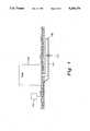
- FIG. 1is a diagram showing the leak detection system of the present invention.
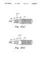
- FIGS. 2(a) and (b)show cutaway perspective views of two embodiments of leak detection cable 104.
- FIG. 3is a block diagram of capacitance measuring circuit 102 of the present invention.
- FIG. 4is a graphical representation of the charging voltage and time for cable 104.
- FIG. 5is a partial schematic diagram detailing capacitance measuring circuit 102.
- a leak detection system 100is shown in FIG. 1 in the environment of a storage tank 106 and a pipeline 108.
- System 100includes a capacitance measuring circuit 102 and a leak detection cable 104.
- Storage tank 106 and pipeline 108contain a chemical (e.g., fuel oil) for which leak detection is desired.
- Cable 104is laid adjacent tank 106 and pipeline 108. One end of cable 104 is connected to capacitive measuring circuit 102. The other end of cable 104 remains unterminated.
- Leak detection cable 104is a conventional leak detection cable as is known in the art.
- the specific cable chosenwill depend on the properties of the liquid to be detected.
- a cablemay be used such as that disclosed in U.S. Pat. No. 4,877,923 to Sahakian and available as part number LLF-0126 (water and liquid chemical cable) or LLF-0118 (hydrocarbon cable) from W. L. Gore & Associates, Inc., Wilmington, Del.
- Examples of other leak detection cablesare disclosed in U.S. Pat. Nos. 3,981,181 to Ochiai, 4,029,889 to Mizuochi, 4,206,632 to Suzuki, 4,594,638 to Suzuki, and, 4,910,998 to Willis et al.
- a first embodiment 104(a) of cable 104is shown in detail in FIG. 2(a). This embodiment can be used for detecting water as well as liquid chemicals.
- Cable 104(a)includes an inner conductor 202, a first insulation layer 204, a second insulation layer 206, a coaxial outer conductor 208, and an outer protective layer 210.
- First insulation layer 204is a hydrophobic, micro-porous insulation such as expanded, micro-porous polytetrafluoroethylene (EPTFE).
- Second insulation layer 206is a polyester braided filler which is permeable so as to pass chemicals, but is not hydrophobic.
- Outer conductor 208is of braided conductive metal construction and is fluid permeable.
- Protective layer 210is a permeable material such as polyethylene or polyester and can be woven or braided.
- a second embodiment 104(b) of cable 104is shown in detail in FIG. 2(b). This embodiment can be used for detecting liquid hydrocarbons.
- Cable 104(b)includes an inner conductor 202, a first insulation layer 204, a coaxial outer conductor 208, an outer hydrophobic layer 209, and an outer protective layer 210.
- First insulation layer 204 and hydrophobic layer 209are both hydrophobic, micro-porous insulation such as EPTFE.
- Outer conductor 208is of braided conductive metal construction and is fluid permeable.
- Protective layer 210is a permeable material such as polyethylene or polyester and can be woven or braided.
- cable 104(a)may be used to sense a variety of liquids (including water), while cable 104(b) is limited to liquids which are capable of permeating hydrophobic layer 209 (e.g., hydrocarbons).
- the operative difference between the cablesis hydrophobic layer 209 of cable 104(b) which prevents water from reaching the conductors such that the impedance of cable 104(b) will not be affected by water.
- Cable 104(a)allows water to be absorbed into second insulation layer 206 between the conductors such that water can be detected.
- leak detection system 100operation of leak detection system 100 is described. If a leak (e.g., leak 110) occurs in tank 106 or pipe 108, the leaking liquid will eventually come into contact with cable 104. In the case of cable 104(a), the liquid will pass through protective layer 210 and conductor 208, and will be absorbed into first insulation layer 204 and second insulation layer 206. The absorbed liquid will cause a change in the dielectric properties of insulation layers 204 and 206. This will result in a change in the capacitance of the cable which can be sensed by capacitance measuring circuit 102 at a remote end of the cable.
- a leake.g., leak 110
- the liquidwill pass through protective layer 210 and contact hydrophobic layer 209. Only hydrocarbons will pass through layer 209 (i.e., water will be excluded). The hydrocarbon will then pass through outer conductor 208 and will be absorbed into first insulation 204. As with cable 104(a), the absorbed liquid will cause a change in the dielectric properties of insulation layer 204, resulting in a corresponding change in the capacitance of the cable which can be sensed by capacitance measuring circuit 102.
- Capacitance measuring circuit 102is shown in FIG. 3.
- a voltage source 302provides a stable DC voltage (V IN ) to a first input of a comparator circuit 312 and to an input (terminal 320) of inverter circuit 304.
- Inverter circuit 304inverts V IN from voltage source 302 and provides a mirror-image inverted DC voltage (-V IN ) to an input (terminal 322) of a constant current source 306.
- Current source 306has an output terminal 318.
- Cable 104having a capacitance C x which is to be measured, is connected between terminal 318 and ground.
- Inner conductor 202 of cable 104is connected to terminal 318 while outer conductor 208 is tied to ground.
- Current source 306provides a constant DC charging current (I c ) to cable 104.
- a digitally controlled, analog switch 308is connected in shunt fashion across cable 104 (i.e., between terminal 318 and ground).
- Terminal 318is also connected to a second input of comparator circuit 312.
- the output of comparator circuit 312is input to a microcontroller unit (MCU) 316.
- MCU 316provides an output signal to a display unit 314, and a control signal to digitally controlled analog switch 308.
- a keypad 315is provided as a user-interface to MCU 316.
- switch 308is CLOSED. In this position, switch 308 shorts terminal 318 to ground such that the net voltage between conductors 202 and 208 of cable 104 is zero. Output current I c from output terminal 318 is shunted to ground through switch 308.
- MCU 316causes switch 308 to toggle OPEN. I C then loses its direct path to ground through switch 308 and is forced to flow through cable 104. This causes the cable to be charged.
- V CAs a result of the charging, a net voltage V C is developed between the conductors of cable 104.
- Comparator circuit 312continuously compares V C (as seen at terminal 318) to V IN .
- V Cbecomes equal to V IN , causing comparator circuit 312 to toggle and send a match signal to MCU 316 indicating that V C has reached the desired level.
- Equation 4illustrates that the measured value C X of cable 104 is independent of V IN . This eliminates voltage related errors from circuit 102, and eliminates the need for calibration. The result is an accurate and stable capacitive measuring apparatus which is simple and contains relatively few parts.
- MCU 316After determining the value of capacitance C X , MCU 316 will compare the measured value of C X to a range of predetermined acceptable limits. If the value of C X does not fall within the range of acceptable limits, then MCU 316 may generate an alarm signal indicating a leak or broken cable condition. Keypad 315 and display 314 provide a user interface to MCU 316.
- FIG. 5is a schematic diagram of inverter 304, current source 306, comparator circuit 312, and switch 308 of capacitance measuring circuit 102.
- Inverter 304includes a resistor R1, a resistor R2, and an operational amplifier U1.
- U1, R1 and R2are connected in an inverting amplifier configuration with R1 connected between terminal 320 and the inverting input of U1.
- Resistor R2is connected between the inverting input and the output (terminal 322) of U1.
- the non-inverting input of U1is connected to ground.
- inverter 304produces an output voltage at terminal 322 defined by the following equation.
- the output voltage of inverter 304is fed to the input of current source 306.
- Current source 306includes operation amplifier U2, and resistors R3-R7.
- the voltage at terminal 322 (-V IN )is fed to the inverting input of U2 through R3.
- R4provides feedback from the output of U2 to the inverting input of U2.
- the non-inverting input of U2is connected to ground through R5.
- R7is connected between the output of U2 and output terminal 318.
- R6is connected between output terminal 318 and the non-inverting input of U2.
- Cable 104is represented as a capacitance C X connected from output terminal 318 to ground.
- Comparator circuit 312monitors the voltage at terminal 318.
- Comparator circuit 312includes comparator U3 and resistor R8.
- the non-inverting input of U3is connected to V IN .
- R8is connected from the output terminal of U3 to the non-inverting input of the same.
- the inverting input of U3is connected to terminal 318.
- the output of comparator circuit 312is connected to MCU 316.
- the only error sources remaining in the circuitare the non-ideal characteristics of the circuit components. These include leakage and bias currents of operational amplifiers U1 and U2, propagation delays through the circuit, and resistor value variations. Each of these variables comprises an initial tolerance (e.g., initial deviation from ideal), a temperature variation, and an end-of-life variation (i.e., aging). The effects of initial tolerances may be eliminated by "trimming" circuit 102 during a one time calibration at manufacture.
- U1 and U2are MC33282P operational amplifiers from Motorola Semiconductor Products, Inc., Phoenix, Ariz. Voltage comparator U3 is available from Texas Instruments Incorporated, Dallas, Tex., as part number LC372IP. MCU 316 is an MC68HC811E2FN microcontroller, also from Motorola. Digitally controlled analog switch 308 is available from Siliconix Incorporated, Santa Clara, Calif., as part number DG401AK. Alternatively, switch 308 may be a transistor.
- Display 314is a 2 ⁇ 16 Dot Matrix LCD (Liquid Crystal Display), part number L1642 from Seiko Instruments USA, Inc., Torrance, Calif.
- Keypad 315is a one by four membrane keypad available from W.H. Brady Company, Xymox Division, Milwaukee, Wis., under part number 2012084.
- V INis a +5 Volt DC voltage.
- Resistors R1-R8are 1% tolerance, carbon composition resistors having the following values:
- comparator 312is tied to an edge-sensitive input capture pin PA2 (pin 32) of MCU 316.
- the armature of switch 308is controlled by pin PC3 (pin 12) of MCU 316.
- PC3 (pin 12) of MCU 316is also connected to an edge-sensitive input capture pin PA1 (pin 33) of MCU 316.
- leak detection system 100For fuel oil leak detection, operation of leak detection system 100 would be as follows. Assuming that cable 104 is 100 feet in length and has a distributed capacitance of 23 pF/foot, then the nominal or reference capacitance (C REF ) measured by circuit 102 will be 2300 pF (e.g. corresponding to a charge time of 2300 ⁇ sec). Given that fuel oil will change the capacitance of cable 104 by 12 pF/foot, and that it is desired to indicate a leak when at least two feet of cable 104 are in contact with leaking oil, then MCU 316 may be programmed to sound an alarm when the capacitance of the cable exceeds a predetermined leak detection threshold (LDT). Similarly, a break in the cable may be sensed as a decrease in the capacitance of the line, and an alarm sounded when the capacitance falls below a predetermined cable break threshold (CBT).
- LDTleak detection threshold
- CBTcable break threshold
- the predetermined thresholdsmay be determined in accordance with the following considerations.
- a capacitance change of approximately ⁇ 5 pFhas been found to be a suitable threshold for a cable 230 feet long.
- each thresholdshould be adjusted to account for variation of the cable capacitance due to temperature. With shorter cable lengths (e.g., ⁇ 230 feet), temperature effects are small and may be ignored.
- the per foot capacitance change per degreei.e., pF/(foot ⁇ degree)
- pF/(foot ⁇ degree)has an increasing effect, and should not be ignored.
- Examples of several cable lengths for a 23 pF/foot cable which exhibits a 12 pF/foot change in impedance when contacted by the leaking liquidare listed below in Table I.
- LDT and CBTwere calculated according to the equations listed above.
- L WETrepresents the length of cable which must contact the leaking liquid in order to exceed the LDT.
- L CUTrepresents the length of a portion of cable which must be cut in order to fall below the CBT.
- a current limit resistormay be placed between terminal 318 and capacitance C X in series connection to meet Underwriter's Laboratories intrinsic safety requirements for electrical apparatus for monitoring in hazardous locations.
- a wire-wound 120 ⁇ , 3 Watt resistoris used in the preferred embodiment. This resistor will limit the current that can be drawn by cable 104 in the event of an internal short-circuit failure of circuit 102. Because I C is a very small current, only a negligible voltage drop will occur across this resistor, such that no significant measurement error will be introduced.
- TDRtime domain reflectometry
- capacitance measuring circuit 102can be used with any length of cable. It should be further understood, that capacitance measuring circuit 102 has many applications in addition to that of leak detection. For example, circuit 102 could be used as a general purpose capacitance measuring circuit.
Landscapes
- Physics & Mathematics (AREA)
- General Physics & Mathematics (AREA)
- Measurement Of Resistance Or Impedance (AREA)
- Investigating Or Analyzing Materials By The Use Of Electric Means (AREA)
- Examining Or Testing Airtightness (AREA)
- Testing Of Short-Circuits, Discontinuities, Leakage, Or Incorrect Line Connections (AREA)
Abstract
Description
______________________________________ Resistor Value ______________________________________ R1 1 MΩ R2 1 MΩ R3 2 MΩ R4 1 MΩ R5 2 MΩ R6 500 KΩ R7 500 KΩ R8 5.1 KΩ ______________________________________
TABLE I ______________________________________ CABLE LENGTH C.sub.REF LDT CBT L.sub.WET L.sub.CUT ______________________________________ 1000' 23,000 pF 23,105 22,895 8.75' 4.6' 100' 2,300 pF 2,315 2,285 1.25' .65' 10' 230 pF 236 224 .50' .26' 1' 23 pF 28 18 .42' .22' ______________________________________
Claims (20)
Priority Applications (6)
| Application Number | Priority Date | Filing Date | Title |
|---|---|---|---|
| US07/726,479US5159276A (en) | 1991-07-08 | 1991-07-08 | Capacitance measuring circuit and method for liquid leak detection by measuring charging time |
| PCT/US1992/005701WO1993001482A1 (en) | 1991-07-08 | 1992-07-08 | Capacitance measuring circuit and method for liquid leak detection |
| EP92915534AEP0547211A1 (en) | 1991-07-08 | 1992-07-08 | Capacitance measuring circuit and method for liquid leak detection |
| AU23373/92AAU643157B2 (en) | 1991-07-08 | 1992-07-08 | Capacitance measuring circuit and method for liquid leak detection |
| CA002089873ACA2089873A1 (en) | 1991-07-08 | 1992-07-08 | Capacitance measuring circuit and method for liquid leak detection |
| JP5502391AJPH06503178A (en) | 1991-07-08 | 1992-07-08 | Capacitance measurement circuit and liquid leakage detection method |
Applications Claiming Priority (1)
| Application Number | Priority Date | Filing Date | Title |
|---|---|---|---|
| US07/726,479US5159276A (en) | 1991-07-08 | 1991-07-08 | Capacitance measuring circuit and method for liquid leak detection by measuring charging time |
Publications (1)
| Publication Number | Publication Date |
|---|---|
| US5159276Atrue US5159276A (en) | 1992-10-27 |
Family
ID=24918774
Family Applications (1)
| Application Number | Title | Priority Date | Filing Date |
|---|---|---|---|
| US07/726,479Expired - Fee RelatedUS5159276A (en) | 1991-07-08 | 1991-07-08 | Capacitance measuring circuit and method for liquid leak detection by measuring charging time |
Country Status (6)
| Country | Link |
|---|---|
| US (1) | US5159276A (en) |
| EP (1) | EP0547211A1 (en) |
| JP (1) | JPH06503178A (en) |
| AU (1) | AU643157B2 (en) |
| CA (1) | CA2089873A1 (en) |
| WO (1) | WO1993001482A1 (en) |
Cited By (65)
| Publication number | Priority date | Publication date | Assignee | Title |
|---|---|---|---|---|
| WO1993025883A1 (en)* | 1992-06-04 | 1993-12-23 | Midwesco, Inc. | Corrosion resistant cable |
| US5316035A (en)* | 1993-02-19 | 1994-05-31 | Fluoroware, Inc. | Capacitive proximity monitoring device for corrosive atmosphere environment |
| US5410255A (en)* | 1993-05-07 | 1995-04-25 | Perma-Pipe, Inc. | Method and apparatus for detecting and distinguishing leaks using reflectometry and conductivity tests |
| US5453698A (en)* | 1994-09-28 | 1995-09-26 | Ventirtex, Inc. | Method and system for testing an implantable defibrillator output stage and high voltage lead integrity |
| WO1997023738A1 (en)* | 1995-12-26 | 1997-07-03 | Harald Philipp | Charge transfer capacitance sensor |
| US6498499B1 (en)* | 1998-03-07 | 2002-12-24 | Sikora Industrieelektronik Gmbh | Device for measuring the capacitance of electrical wires |
| US6559657B1 (en)* | 1999-01-13 | 2003-05-06 | Endress+Hauser Gmbh+Co. | Probe mapping diagnostic methods |
| US6611921B2 (en) | 2001-09-07 | 2003-08-26 | Microsoft Corporation | Input device with two input signal generating means having a power state where one input means is powered down and the other input means is cycled between a powered up state and a powered down state |
| US6650125B1 (en) | 2001-12-06 | 2003-11-18 | The United States Of America As Represented By The Administrator Of The National Aeronautics And Space Administration | Leak and pipe detection method and system |
| US6703599B1 (en) | 2002-01-30 | 2004-03-09 | Microsoft Corporation | Proximity sensor with adaptive threshold |
| US6717415B2 (en)* | 2002-02-05 | 2004-04-06 | Logicvision, Inc. | Circuit and method for determining the location of defect in a circuit |
| US20050098343A1 (en)* | 2003-11-07 | 2005-05-12 | Tanita Corporation | Shielded cable, and bioelectrical impedance value or biological composition data acquiring apparatus using the same |
| US20050116725A1 (en)* | 2003-12-01 | 2005-06-02 | Raymond Donald M. | Fluid detection cable |
| US6954867B2 (en) | 2002-07-26 | 2005-10-11 | Microsoft Corporation | Capacitive sensing employing a repeatable offset charge |
| US20060032658A1 (en)* | 2004-08-16 | 2006-02-16 | Chiaki Abe | Coaxial cable |
| US20070051166A1 (en)* | 2005-09-02 | 2007-03-08 | Baker Kenneth R | Leak detection systems and methods |
| KR100766627B1 (en)* | 1998-01-26 | 2007-10-15 | 핑거웍스, 인크. | Manual input integration method and device |
| US20090301172A1 (en)* | 2008-06-06 | 2009-12-10 | Raymond Donald M | Twisted leak detection cable |
| US20100288017A1 (en)* | 2009-05-12 | 2010-11-18 | Raymond Donald M | Aqueous chemical leak detection cable |
| US20110048110A1 (en)* | 2009-05-12 | 2011-03-03 | Raymond Donald M | Aqueous chemical leak detection cable |
| US20120032811A1 (en)* | 2010-08-06 | 2012-02-09 | Lee Yeu Yong | Leak detection system having power and communication lines |
| US8283800B2 (en) | 2010-05-27 | 2012-10-09 | Ford Global Technologies, Llc | Vehicle control system with proximity switch and method thereof |
| US20130206359A1 (en)* | 2010-10-22 | 2013-08-15 | Alfa Laval Corporate Ab | Heat exchanger plate and a plate heat exchanger |
| US8796575B2 (en) | 2012-10-31 | 2014-08-05 | Ford Global Technologies, Llc | Proximity switch assembly having ground layer |
| US8878438B2 (en) | 2011-11-04 | 2014-11-04 | Ford Global Technologies, Llc | Lamp and proximity switch assembly and method |
| US8922340B2 (en) | 2012-09-11 | 2014-12-30 | Ford Global Technologies, Llc | Proximity switch based door latch release |
| US8928336B2 (en) | 2011-06-09 | 2015-01-06 | Ford Global Technologies, Llc | Proximity switch having sensitivity control and method therefor |
| US8933708B2 (en) | 2012-04-11 | 2015-01-13 | Ford Global Technologies, Llc | Proximity switch assembly and activation method with exploration mode |
| US8975903B2 (en) | 2011-06-09 | 2015-03-10 | Ford Global Technologies, Llc | Proximity switch having learned sensitivity and method therefor |
| US8981602B2 (en) | 2012-05-29 | 2015-03-17 | Ford Global Technologies, Llc | Proximity switch assembly having non-switch contact and method |
| US8994228B2 (en) | 2011-11-03 | 2015-03-31 | Ford Global Technologies, Llc | Proximity switch having wrong touch feedback |
| US9065447B2 (en) | 2012-04-11 | 2015-06-23 | Ford Global Technologies, Llc | Proximity switch assembly and method having adaptive time delay |
| US9136840B2 (en) | 2012-05-17 | 2015-09-15 | Ford Global Technologies, Llc | Proximity switch assembly having dynamic tuned threshold |
| US9143126B2 (en) | 2011-09-22 | 2015-09-22 | Ford Global Technologies, Llc | Proximity switch having lockout control for controlling movable panel |
| US9184745B2 (en) | 2012-04-11 | 2015-11-10 | Ford Global Technologies, Llc | Proximity switch assembly and method of sensing user input based on signal rate of change |
| US9197206B2 (en) | 2012-04-11 | 2015-11-24 | Ford Global Technologies, Llc | Proximity switch having differential contact surface |
| WO2015183465A1 (en)* | 2014-05-28 | 2015-12-03 | 3M Innovative Properties Company | Liquid leakage detector and method for detecting liquid leakage |
| US9219472B2 (en) | 2012-04-11 | 2015-12-22 | Ford Global Technologies, Llc | Proximity switch assembly and activation method using rate monitoring |
| US9287864B2 (en) | 2012-04-11 | 2016-03-15 | Ford Global Technologies, Llc | Proximity switch assembly and calibration method therefor |
| US9311204B2 (en) | 2013-03-13 | 2016-04-12 | Ford Global Technologies, Llc | Proximity interface development system having replicator and method |
| US9337832B2 (en) | 2012-06-06 | 2016-05-10 | Ford Global Technologies, Llc | Proximity switch and method of adjusting sensitivity therefor |
| US20160273995A1 (en)* | 2013-11-15 | 2016-09-22 | Eaton Corporation | Electrically conductive polymers as sensing media to detect leaks in aerospace pneumatic ducts |
| US9520875B2 (en) | 2012-04-11 | 2016-12-13 | Ford Global Technologies, Llc | Pliable proximity switch assembly and activation method |
| US9531379B2 (en) | 2012-04-11 | 2016-12-27 | Ford Global Technologies, Llc | Proximity switch assembly having groove between adjacent proximity sensors |
| US9548733B2 (en) | 2015-05-20 | 2017-01-17 | Ford Global Technologies, Llc | Proximity sensor assembly having interleaved electrode configuration |
| US9559688B2 (en) | 2012-04-11 | 2017-01-31 | Ford Global Technologies, Llc | Proximity switch assembly having pliable surface and depression |
| US9568527B2 (en) | 2012-04-11 | 2017-02-14 | Ford Global Technologies, Llc | Proximity switch assembly and activation method having virtual button mode |
| US9641172B2 (en) | 2012-06-27 | 2017-05-02 | Ford Global Technologies, Llc | Proximity switch assembly having varying size electrode fingers |
| US9654103B2 (en) | 2015-03-18 | 2017-05-16 | Ford Global Technologies, Llc | Proximity switch assembly having haptic feedback and method |
| US9660644B2 (en) | 2012-04-11 | 2017-05-23 | Ford Global Technologies, Llc | Proximity switch assembly and activation method |
| US9831870B2 (en) | 2012-04-11 | 2017-11-28 | Ford Global Technologies, Llc | Proximity switch assembly and method of tuning same |
| US9921125B2 (en) | 2014-03-27 | 2018-03-20 | Nxp Usa, Inc. | Leak detector using capacitance sensor |
| US9944237B2 (en) | 2012-04-11 | 2018-04-17 | Ford Global Technologies, Llc | Proximity switch assembly with signal drift rejection and method |
| US10004286B2 (en) | 2011-08-08 | 2018-06-26 | Ford Global Technologies, Llc | Glove having conductive ink and method of interacting with proximity sensor |
| US10038443B2 (en) | 2014-10-20 | 2018-07-31 | Ford Global Technologies, Llc | Directional proximity switch assembly |
| US10112556B2 (en) | 2011-11-03 | 2018-10-30 | Ford Global Technologies, Llc | Proximity switch having wrong touch adaptive learning and method |
| KR101939660B1 (en)* | 2018-09-04 | 2019-01-17 | 성백명 | Fire and harmful chemical solution leak notification apparatus |
| WO2019021283A1 (en)* | 2017-07-24 | 2019-01-31 | Swissa Shai Shalom | Leak detection and locating system and method |
| KR101983660B1 (en)* | 2018-08-29 | 2019-05-29 | 성백명 | Leak detection apparatus |
| KR101993467B1 (en)* | 2018-10-08 | 2019-09-30 | 한국소방산업기술원 | harmful chemical leak alarm system |
| US20190339152A1 (en)* | 2018-05-04 | 2019-11-07 | Ademco Inc. | Capacitive leak and flammable vapor detection system |
| CN111766024A (en)* | 2020-08-06 | 2020-10-13 | 中国人民解放军海军潜艇学院 | Demonstration test bench and method for testing compressed gas pipelines of underwater carriers |
| US11016001B2 (en)* | 2018-10-01 | 2021-05-25 | Dell Products L.P. | Systems and methods for leak detection in liquid-cooled information handling systems |
| WO2021116233A1 (en) | 2019-12-13 | 2021-06-17 | bygg AI GmbH | Identification and location of moisture underneath roof coverings |
| DE102021002979A1 (en) | 2021-06-11 | 2022-12-15 | bygg Al GmbH | Method and device for detecting and locating moisture on moisture-carrying surfaces and/or in moisture-carrying layers |
Families Citing this family (2)
| Publication number | Priority date | Publication date | Assignee | Title |
|---|---|---|---|---|
| DE4409027A1 (en)* | 1994-03-16 | 1995-09-21 | P & P Geotechnik Gmbh | Decontaminating organic-charged aq. effluents or residues |
| US8344865B2 (en)* | 2010-10-29 | 2013-01-01 | GM Global Technology Operations LLC | Method and apparatus for monitoring a vehicular propulsion system battery |
Citations (13)
| Publication number | Priority date | Publication date | Assignee | Title |
|---|---|---|---|---|
| US3452272A (en)* | 1967-08-29 | 1969-06-24 | Railway Communications Inc | Method and apparatus for measuring capacitance at repeated intervals including average value indicating means |
| US3581196A (en)* | 1968-10-28 | 1971-05-25 | William L Spaid | Digital capacitance meter by measuring capacitor discharge time |
| US3761805A (en)* | 1971-06-24 | 1973-09-25 | Western Electric Co | Methods of and systems for measuring capacitance using a constant current charging technique |
| US4032841A (en)* | 1975-11-28 | 1977-06-28 | A. P. C. Industries, Inc. | Method and apparatus for measuring the capacitance of telephone cable pairs |
| US4095174A (en)* | 1976-01-22 | 1978-06-13 | Towa Electric Co., Ltd. | System for detecting leakage faults in a pipeline by measuring the distributed capacitance of sections of a sensing cable buried parallel to said pipeline |
| US4103225A (en)* | 1977-01-05 | 1978-07-25 | Dynatel Corporation | System and method for determining capacitance and cable length in the presence of other circuit elements |
| US4206402A (en)* | 1977-06-02 | 1980-06-03 | Yasuhiro Ishido | System and method for detecting leakage in a pipeline or tank |
| US4243933A (en)* | 1978-09-20 | 1981-01-06 | Analogic Corporation | Capacitance measurement apparatus |
| US4361799A (en)* | 1980-03-27 | 1982-11-30 | Raychem Corporation | Over-temperature sense and locate device |
| US4372693A (en)* | 1981-01-30 | 1983-02-08 | Raychem Corporation | Temperature excursion sensing and locating apparatus |
| US4487057A (en)* | 1980-09-16 | 1984-12-11 | Raychem Corporation | Continuous sense and locate device |
| US4825147A (en)* | 1988-09-14 | 1989-04-25 | Sencore, Inc. | Capacitance measuring method and apparatus |
| US4877923A (en)* | 1988-08-01 | 1989-10-31 | W. L. Gore & Associates, Inc. | Sensors for detecting and locating liquid leaks |
- 1991
- 1991-07-08USUS07/726,479patent/US5159276A/ennot_activeExpired - Fee Related
- 1992
- 1992-07-08CACA002089873Apatent/CA2089873A1/ennot_activeAbandoned
- 1992-07-08JPJP5502391Apatent/JPH06503178A/enactivePending
- 1992-07-08EPEP92915534Apatent/EP0547211A1/ennot_activeCeased
- 1992-07-08AUAU23373/92Apatent/AU643157B2/ennot_activeCeased
- 1992-07-08WOPCT/US1992/005701patent/WO1993001482A1/ennot_activeApplication Discontinuation
Patent Citations (13)
| Publication number | Priority date | Publication date | Assignee | Title |
|---|---|---|---|---|
| US3452272A (en)* | 1967-08-29 | 1969-06-24 | Railway Communications Inc | Method and apparatus for measuring capacitance at repeated intervals including average value indicating means |
| US3581196A (en)* | 1968-10-28 | 1971-05-25 | William L Spaid | Digital capacitance meter by measuring capacitor discharge time |
| US3761805A (en)* | 1971-06-24 | 1973-09-25 | Western Electric Co | Methods of and systems for measuring capacitance using a constant current charging technique |
| US4032841A (en)* | 1975-11-28 | 1977-06-28 | A. P. C. Industries, Inc. | Method and apparatus for measuring the capacitance of telephone cable pairs |
| US4095174A (en)* | 1976-01-22 | 1978-06-13 | Towa Electric Co., Ltd. | System for detecting leakage faults in a pipeline by measuring the distributed capacitance of sections of a sensing cable buried parallel to said pipeline |
| US4103225A (en)* | 1977-01-05 | 1978-07-25 | Dynatel Corporation | System and method for determining capacitance and cable length in the presence of other circuit elements |
| US4206402A (en)* | 1977-06-02 | 1980-06-03 | Yasuhiro Ishido | System and method for detecting leakage in a pipeline or tank |
| US4243933A (en)* | 1978-09-20 | 1981-01-06 | Analogic Corporation | Capacitance measurement apparatus |
| US4361799A (en)* | 1980-03-27 | 1982-11-30 | Raychem Corporation | Over-temperature sense and locate device |
| US4487057A (en)* | 1980-09-16 | 1984-12-11 | Raychem Corporation | Continuous sense and locate device |
| US4372693A (en)* | 1981-01-30 | 1983-02-08 | Raychem Corporation | Temperature excursion sensing and locating apparatus |
| US4877923A (en)* | 1988-08-01 | 1989-10-31 | W. L. Gore & Associates, Inc. | Sensors for detecting and locating liquid leaks |
| US4825147A (en)* | 1988-09-14 | 1989-04-25 | Sencore, Inc. | Capacitance measuring method and apparatus |
Cited By (104)
| Publication number | Priority date | Publication date | Assignee | Title |
|---|---|---|---|---|
| WO1993025883A1 (en)* | 1992-06-04 | 1993-12-23 | Midwesco, Inc. | Corrosion resistant cable |
| US5355720A (en)* | 1992-06-04 | 1994-10-18 | Perma-Pipe, Inc. | Corrosion resistant cable |
| US5316035A (en)* | 1993-02-19 | 1994-05-31 | Fluoroware, Inc. | Capacitive proximity monitoring device for corrosive atmosphere environment |
| US5449017A (en)* | 1993-02-19 | 1995-09-12 | Fluoroware, Inc. | Proximity sensing probe |
| US5410255A (en)* | 1993-05-07 | 1995-04-25 | Perma-Pipe, Inc. | Method and apparatus for detecting and distinguishing leaks using reflectometry and conductivity tests |
| US5453698A (en)* | 1994-09-28 | 1995-09-26 | Ventirtex, Inc. | Method and system for testing an implantable defibrillator output stage and high voltage lead integrity |
| WO1997023738A1 (en)* | 1995-12-26 | 1997-07-03 | Harald Philipp | Charge transfer capacitance sensor |
| US5730165A (en)* | 1995-12-26 | 1998-03-24 | Philipp; Harald | Time domain capacitive field detector |
| GB2337124A (en)* | 1995-12-26 | 1999-11-10 | Harald Philipp | Charge transfer capacitance sensor |
| GB2337124B (en)* | 1995-12-26 | 2000-07-12 | Harald Philipp | Charge transfer capacitance sensor |
| DE19681725B4 (en)* | 1995-12-26 | 2007-04-26 | Harald Southampton Philipp | Charge transfer capacitance sensor - charges sensing electrode for discharge to charge detection circuit with selectable time intervals set by microprocessor program, and transistor type discharging switch |
| KR100766627B1 (en)* | 1998-01-26 | 2007-10-15 | 핑거웍스, 인크. | Manual input integration method and device |
| US6498499B1 (en)* | 1998-03-07 | 2002-12-24 | Sikora Industrieelektronik Gmbh | Device for measuring the capacitance of electrical wires |
| US6559657B1 (en)* | 1999-01-13 | 2003-05-06 | Endress+Hauser Gmbh+Co. | Probe mapping diagnostic methods |
| US6661410B2 (en) | 2001-09-07 | 2003-12-09 | Microsoft Corporation | Capacitive sensing and data input device power management |
| US6816150B2 (en) | 2001-09-07 | 2004-11-09 | Microsoft Corporation | Data input device power management including beacon state |
| US6611921B2 (en) | 2001-09-07 | 2003-08-26 | Microsoft Corporation | Input device with two input signal generating means having a power state where one input means is powered down and the other input means is cycled between a powered up state and a powered down state |
| US6850229B2 (en) | 2001-09-07 | 2005-02-01 | Microsoft Corporation | Capacitive sensing and data input device power management |
| US20050078085A1 (en)* | 2001-09-07 | 2005-04-14 | Microsoft Corporation | Data input device power management including beacon state |
| US20050168438A1 (en)* | 2001-09-07 | 2005-08-04 | Microsoft Corporation | Capacitive sensing and data input device power management |
| US7023425B2 (en) | 2001-09-07 | 2006-04-04 | Microsoft Corporation | Data input device power management including beacon state |
| US6995747B2 (en) | 2001-09-07 | 2006-02-07 | Microsoft Corporation | Capacitive sensing and data input device power management |
| US6650125B1 (en) | 2001-12-06 | 2003-11-18 | The United States Of America As Represented By The Administrator Of The National Aeronautics And Space Administration | Leak and pipe detection method and system |
| US20050146499A1 (en)* | 2002-01-30 | 2005-07-07 | Microsoft Corporation | Proximity sensor with adaptive threshold |
| US7002550B2 (en) | 2002-01-30 | 2006-02-21 | Microsoft Corporation | Proximity sensor with adaptive threshold |
| US6933922B2 (en) | 2002-01-30 | 2005-08-23 | Microsoft Corporation | Proximity sensor with adaptive threshold |
| US20050200603A1 (en)* | 2002-01-30 | 2005-09-15 | Microsoft Corporation | Proximity sensor with adaptive threshold |
| US20040142705A1 (en)* | 2002-01-30 | 2004-07-22 | Microsoft Corporation | Proximity sensor with adaptive threshold |
| US7479944B2 (en) | 2002-01-30 | 2009-01-20 | Microsoft Corporation | Proximity sensor with adaptive threshold |
| US6703599B1 (en) | 2002-01-30 | 2004-03-09 | Microsoft Corporation | Proximity sensor with adaptive threshold |
| US6717415B2 (en)* | 2002-02-05 | 2004-04-06 | Logicvision, Inc. | Circuit and method for determining the location of defect in a circuit |
| US20050240785A1 (en)* | 2002-07-26 | 2005-10-27 | Microsoft Corporation | Capacitive sensing employing a repeatable offset charge |
| US7124312B2 (en) | 2002-07-26 | 2006-10-17 | Microsoft Corporation | Capacitive sensing employing a repeatable offset charge |
| US6954867B2 (en) | 2002-07-26 | 2005-10-11 | Microsoft Corporation | Capacitive sensing employing a repeatable offset charge |
| US20050098343A1 (en)* | 2003-11-07 | 2005-05-12 | Tanita Corporation | Shielded cable, and bioelectrical impedance value or biological composition data acquiring apparatus using the same |
| US7317161B2 (en)* | 2003-11-07 | 2008-01-08 | Tanita Corporation | Shielded cable, and bioelectrical impedance value or biological composition data acquiring apparatus using the same |
| US7081759B2 (en) | 2003-12-01 | 2006-07-25 | Raymond & Lae Engineering, Inc. | Fluid detection cable |
| US20050116725A1 (en)* | 2003-12-01 | 2005-06-02 | Raymond Donald M. | Fluid detection cable |
| US7212009B2 (en) | 2003-12-01 | 2007-05-01 | Raymond & Lae Engineering, Inc. | Fluid detection cable |
| US7105739B2 (en)* | 2004-08-16 | 2006-09-12 | Yosho Co., Ltd. | Coaxial cable |
| US20060032658A1 (en)* | 2004-08-16 | 2006-02-16 | Chiaki Abe | Coaxial cable |
| US20070051166A1 (en)* | 2005-09-02 | 2007-03-08 | Baker Kenneth R | Leak detection systems and methods |
| US20090301172A1 (en)* | 2008-06-06 | 2009-12-10 | Raymond Donald M | Twisted leak detection cable |
| US8063309B2 (en) | 2008-06-06 | 2011-11-22 | Raymond & Lae Engineering, Inc. | Twisted leak detection cable |
| US9755389B2 (en) | 2008-06-06 | 2017-09-05 | Raymond & Lae Engineering, Inc. | Twisted leak detection cable |
| US8601679B2 (en) | 2008-06-06 | 2013-12-10 | Raymond & Lae Engineering, Inc. | Twisted leak detection cable |
| US20100288017A1 (en)* | 2009-05-12 | 2010-11-18 | Raymond Donald M | Aqueous chemical leak detection cable |
| US20110048110A1 (en)* | 2009-05-12 | 2011-03-03 | Raymond Donald M | Aqueous chemical leak detection cable |
| US8234910B2 (en) | 2009-05-12 | 2012-08-07 | Raymond & Lae Engineering, Inc. | Aqueous chemical leak detection cable |
| US8256269B2 (en) | 2009-05-12 | 2012-09-04 | Raymond & Lae Engineering, Inc. | Aqueous chemical leak detection cable |
| US8283800B2 (en) | 2010-05-27 | 2012-10-09 | Ford Global Technologies, Llc | Vehicle control system with proximity switch and method thereof |
| US8786451B2 (en)* | 2010-08-06 | 2014-07-22 | Chang Sung Ace Co., Ltd. | Leak detection system having power and communication lines |
| US20120032811A1 (en)* | 2010-08-06 | 2012-02-09 | Lee Yeu Yong | Leak detection system having power and communication lines |
| US9739546B2 (en)* | 2010-10-22 | 2017-08-22 | Alfa Laval Corporate Ab | Heat exchanger plate and a plate heat exchanger with insulated sensor internal to heat exchange area |
| US20130206359A1 (en)* | 2010-10-22 | 2013-08-15 | Alfa Laval Corporate Ab | Heat exchanger plate and a plate heat exchanger |
| US8928336B2 (en) | 2011-06-09 | 2015-01-06 | Ford Global Technologies, Llc | Proximity switch having sensitivity control and method therefor |
| US8975903B2 (en) | 2011-06-09 | 2015-03-10 | Ford Global Technologies, Llc | Proximity switch having learned sensitivity and method therefor |
| US10595574B2 (en) | 2011-08-08 | 2020-03-24 | Ford Global Technologies, Llc | Method of interacting with proximity sensor with a glove |
| US10004286B2 (en) | 2011-08-08 | 2018-06-26 | Ford Global Technologies, Llc | Glove having conductive ink and method of interacting with proximity sensor |
| US9143126B2 (en) | 2011-09-22 | 2015-09-22 | Ford Global Technologies, Llc | Proximity switch having lockout control for controlling movable panel |
| US10112556B2 (en) | 2011-11-03 | 2018-10-30 | Ford Global Technologies, Llc | Proximity switch having wrong touch adaptive learning and method |
| US10501027B2 (en) | 2011-11-03 | 2019-12-10 | Ford Global Technologies, Llc | Proximity switch having wrong touch adaptive learning and method |
| US8994228B2 (en) | 2011-11-03 | 2015-03-31 | Ford Global Technologies, Llc | Proximity switch having wrong touch feedback |
| US8878438B2 (en) | 2011-11-04 | 2014-11-04 | Ford Global Technologies, Llc | Lamp and proximity switch assembly and method |
| US9520875B2 (en) | 2012-04-11 | 2016-12-13 | Ford Global Technologies, Llc | Pliable proximity switch assembly and activation method |
| US9944237B2 (en) | 2012-04-11 | 2018-04-17 | Ford Global Technologies, Llc | Proximity switch assembly with signal drift rejection and method |
| US9184745B2 (en) | 2012-04-11 | 2015-11-10 | Ford Global Technologies, Llc | Proximity switch assembly and method of sensing user input based on signal rate of change |
| US9219472B2 (en) | 2012-04-11 | 2015-12-22 | Ford Global Technologies, Llc | Proximity switch assembly and activation method using rate monitoring |
| US9287864B2 (en) | 2012-04-11 | 2016-03-15 | Ford Global Technologies, Llc | Proximity switch assembly and calibration method therefor |
| US8933708B2 (en) | 2012-04-11 | 2015-01-13 | Ford Global Technologies, Llc | Proximity switch assembly and activation method with exploration mode |
| US9568527B2 (en) | 2012-04-11 | 2017-02-14 | Ford Global Technologies, Llc | Proximity switch assembly and activation method having virtual button mode |
| US9197206B2 (en) | 2012-04-11 | 2015-11-24 | Ford Global Technologies, Llc | Proximity switch having differential contact surface |
| US9831870B2 (en) | 2012-04-11 | 2017-11-28 | Ford Global Technologies, Llc | Proximity switch assembly and method of tuning same |
| US9660644B2 (en) | 2012-04-11 | 2017-05-23 | Ford Global Technologies, Llc | Proximity switch assembly and activation method |
| US9531379B2 (en) | 2012-04-11 | 2016-12-27 | Ford Global Technologies, Llc | Proximity switch assembly having groove between adjacent proximity sensors |
| US9065447B2 (en) | 2012-04-11 | 2015-06-23 | Ford Global Technologies, Llc | Proximity switch assembly and method having adaptive time delay |
| US9559688B2 (en) | 2012-04-11 | 2017-01-31 | Ford Global Technologies, Llc | Proximity switch assembly having pliable surface and depression |
| US9136840B2 (en) | 2012-05-17 | 2015-09-15 | Ford Global Technologies, Llc | Proximity switch assembly having dynamic tuned threshold |
| US8981602B2 (en) | 2012-05-29 | 2015-03-17 | Ford Global Technologies, Llc | Proximity switch assembly having non-switch contact and method |
| US9337832B2 (en) | 2012-06-06 | 2016-05-10 | Ford Global Technologies, Llc | Proximity switch and method of adjusting sensitivity therefor |
| US9641172B2 (en) | 2012-06-27 | 2017-05-02 | Ford Global Technologies, Llc | Proximity switch assembly having varying size electrode fingers |
| US9447613B2 (en) | 2012-09-11 | 2016-09-20 | Ford Global Technologies, Llc | Proximity switch based door latch release |
| US8922340B2 (en) | 2012-09-11 | 2014-12-30 | Ford Global Technologies, Llc | Proximity switch based door latch release |
| US8796575B2 (en) | 2012-10-31 | 2014-08-05 | Ford Global Technologies, Llc | Proximity switch assembly having ground layer |
| US9311204B2 (en) | 2013-03-13 | 2016-04-12 | Ford Global Technologies, Llc | Proximity interface development system having replicator and method |
| US9989435B2 (en)* | 2013-11-15 | 2018-06-05 | Eaton Intelligent Power Limited | Electrically conductive polymers as sensing media to detect leaks in aerospace pneumatic ducts |
| US20160273995A1 (en)* | 2013-11-15 | 2016-09-22 | Eaton Corporation | Electrically conductive polymers as sensing media to detect leaks in aerospace pneumatic ducts |
| US9921125B2 (en) | 2014-03-27 | 2018-03-20 | Nxp Usa, Inc. | Leak detector using capacitance sensor |
| WO2015183465A1 (en)* | 2014-05-28 | 2015-12-03 | 3M Innovative Properties Company | Liquid leakage detector and method for detecting liquid leakage |
| US10038443B2 (en) | 2014-10-20 | 2018-07-31 | Ford Global Technologies, Llc | Directional proximity switch assembly |
| US9654103B2 (en) | 2015-03-18 | 2017-05-16 | Ford Global Technologies, Llc | Proximity switch assembly having haptic feedback and method |
| US9548733B2 (en) | 2015-05-20 | 2017-01-17 | Ford Global Technologies, Llc | Proximity sensor assembly having interleaved electrode configuration |
| WO2019021283A1 (en)* | 2017-07-24 | 2019-01-31 | Swissa Shai Shalom | Leak detection and locating system and method |
| US10697846B2 (en)* | 2018-05-04 | 2020-06-30 | Ademco Inc. | Capacitive leak and flammable vapor detection system |
| US20190339152A1 (en)* | 2018-05-04 | 2019-11-07 | Ademco Inc. | Capacitive leak and flammable vapor detection system |
| KR101983660B1 (en)* | 2018-08-29 | 2019-05-29 | 성백명 | Leak detection apparatus |
| KR101939660B1 (en)* | 2018-09-04 | 2019-01-17 | 성백명 | Fire and harmful chemical solution leak notification apparatus |
| US11016001B2 (en)* | 2018-10-01 | 2021-05-25 | Dell Products L.P. | Systems and methods for leak detection in liquid-cooled information handling systems |
| KR101993467B1 (en)* | 2018-10-08 | 2019-09-30 | 한국소방산업기술원 | harmful chemical leak alarm system |
| WO2021116233A1 (en) | 2019-12-13 | 2021-06-17 | bygg AI GmbH | Identification and location of moisture underneath roof coverings |
| DE102019134398B4 (en) | 2019-12-13 | 2021-07-08 | bygg AI GmbH | Apparatus and method for detecting and localizing moisture |
| CN111766024A (en)* | 2020-08-06 | 2020-10-13 | 中国人民解放军海军潜艇学院 | Demonstration test bench and method for testing compressed gas pipelines of underwater carriers |
| DE102021002979A1 (en) | 2021-06-11 | 2022-12-15 | bygg Al GmbH | Method and device for detecting and locating moisture on moisture-carrying surfaces and/or in moisture-carrying layers |
| WO2022258766A1 (en) | 2021-06-11 | 2022-12-15 | bygg AI GmbH | Method and device for detecting and locating moisture on moisture-carrying surfaces and/or in moisture-carrying layers |
Also Published As
| Publication number | Publication date |
|---|---|
| AU643157B2 (en) | 1993-11-04 |
| WO1993001482A1 (en) | 1993-01-21 |
| EP0547211A1 (en) | 1993-06-23 |
| CA2089873A1 (en) | 1993-01-09 |
| AU2337392A (en) | 1993-02-11 |
| JPH06503178A (en) | 1994-04-07 |
Similar Documents
| Publication | Publication Date | Title |
|---|---|---|
| US5159276A (en) | Capacitance measuring circuit and method for liquid leak detection by measuring charging time | |
| US5015958A (en) | Elongate sensors comprising conductive polymers, and methods and apparatus using such sensors | |
| US3993947A (en) | Admittance measuring system for monitoring the condition of materials | |
| US5652521A (en) | Insulation monitoring system for insulated high voltage apparatus | |
| EP0752109A1 (en) | System for calibrating a line isolation monitor | |
| US4206402A (en) | System and method for detecting leakage in a pipeline or tank | |
| EP0752107A1 (en) | System for measuring line to ground impedance | |
| EP0624292A1 (en) | Near-end communications line characteristic measuring system | |
| AU748288B2 (en) | Method and device for monitoring an electrode line of a bipolar high voltage direct current (HVDC) transmission system | |
| US3700966A (en) | Monitoring circuit for detecting leakage currents | |
| EP0133748B1 (en) | Method for detecting and obtaining information about changes in variables | |
| EP0418321B1 (en) | A system and a method for detecting and locating liquid leaks | |
| US3821642A (en) | Corrosion measuring bridge circuit having automatic controlled constant source of energy and temperature compensation | |
| US5382909A (en) | Method for detecting and obtaining information about changes in variables | |
| JPH01502391A (en) | Cable failure detection device | |
| EP0843823B1 (en) | Detection and location of current leakage paths | |
| US3259893A (en) | Holiday detector | |
| WO1994016303A1 (en) | System and method for detecting and locating a leaking liquid | |
| US4322728A (en) | Multichannel remote transducer monitoring system | |
| US3909709A (en) | Conductivity measuring apparatus | |
| GB2220494A (en) | A system for the detection and location of leaks | |
| GB2166248A (en) | Detecting resistance faults | |
| SU1712736A1 (en) | Device for location of leaks in insulated pipe lines | |
| US3831083A (en) | Conductivity and specific resistance measuring system | |
| US3987390A (en) | Method and apparatus for determining resistance at radio frequencies |
Legal Events
| Date | Code | Title | Description |
|---|---|---|---|
| AS | Assignment | Owner name:W. L. GORE & ASSOCIATES, INC., A CORPORATION OF DE Free format text:ASSIGNMENT OF ASSIGNORS INTEREST.;ASSIGNOR:REDDY, WILLIAM J., III;REEL/FRAME:005796/0005 Effective date:19910701 | |
| FEPP | Fee payment procedure | Free format text:PAYOR NUMBER ASSIGNED (ORIGINAL EVENT CODE: ASPN); ENTITY STATUS OF PATENT OWNER: LARGE ENTITY | |
| FPAY | Fee payment | Year of fee payment:4 | |
| FPAY | Fee payment | Year of fee payment:8 | |
| REMI | Maintenance fee reminder mailed | ||
| LAPS | Lapse for failure to pay maintenance fees | ||
| STCH | Information on status: patent discontinuation | Free format text:PATENT EXPIRED DUE TO NONPAYMENT OF MAINTENANCE FEES UNDER 37 CFR 1.362 | |
| FP | Lapsed due to failure to pay maintenance fee | Effective date:20041027 | |
| AS | Assignment | Owner name:GORE ENTERPRISE HOLDINGS, INC., DELAWARE Free format text:CORRECTIVE ACTION TO RECORD REMAINING 30 PATENTS OMITTED FROM ORIGINAL RECORDATION REEL/FRAME 6374/0518;ASSIGNOR:W. L. GORE & ASSOCIATES, INC.;REEL/FRAME:022742/0988 Effective date:19921221 | |
| AS | Assignment | Owner name:W. L. GORE & ASSOCIATES, INC., DELAWARE Free format text:ASSIGNMENT OF ASSIGNORS INTEREST;ASSIGNOR:GORE ENTERPRISE HOLDINGS, INC.;REEL/FRAME:027906/0508 Effective date:20120130 |