US5159181A - Capacitive code reader with interelectrode shielding - Google Patents
Capacitive code reader with interelectrode shieldingDownload PDFInfo
- Publication number
- US5159181A US5159181AUS07/592,493US59249390AUS5159181AUS 5159181 AUS5159181 AUS 5159181AUS 59249390 AUS59249390 AUS 59249390AUS 5159181 AUS5159181 AUS 5159181A
- Authority
- US
- United States
- Prior art keywords
- electrodes
- array
- reader
- code
- bars
- Prior art date
- Legal status (The legal status is an assumption and is not a legal conclusion. Google has not performed a legal analysis and makes no representation as to the accuracy of the status listed.)
- Expired - Lifetime
Links
Images


Classifications
- G—PHYSICS
- G06—COMPUTING OR CALCULATING; COUNTING
- G06K—GRAPHICAL DATA READING; PRESENTATION OF DATA; RECORD CARRIERS; HANDLING RECORD CARRIERS
- G06K19/00—Record carriers for use with machines and with at least a part designed to carry digital markings
- G06K19/06—Record carriers for use with machines and with at least a part designed to carry digital markings characterised by the kind of the digital marking, e.g. shape, nature, code
- G06K19/067—Record carriers with conductive marks, printed circuits or semiconductor circuit elements, e.g. credit or identity cards also with resonating or responding marks without active components
- G—PHYSICS
- G06—COMPUTING OR CALCULATING; COUNTING
- G06K—GRAPHICAL DATA READING; PRESENTATION OF DATA; RECORD CARRIERS; HANDLING RECORD CARRIERS
- G06K1/00—Methods or arrangements for marking the record carrier in digital fashion
- G06K1/12—Methods or arrangements for marking the record carrier in digital fashion otherwise than by punching
- G06K1/126—Methods or arrangements for marking the record carrier in digital fashion otherwise than by punching by photographic or thermographic registration
- G—PHYSICS
- G06—COMPUTING OR CALCULATING; COUNTING
- G06K—GRAPHICAL DATA READING; PRESENTATION OF DATA; RECORD CARRIERS; HANDLING RECORD CARRIERS
- G06K7/00—Methods or arrangements for sensing record carriers, e.g. for reading patterns
- G06K7/08—Methods or arrangements for sensing record carriers, e.g. for reading patterns by means detecting the change of an electrostatic or magnetic field, e.g. by detecting change of capacitance between electrodes
- G06K7/081—Methods or arrangements for sensing record carriers, e.g. for reading patterns by means detecting the change of an electrostatic or magnetic field, e.g. by detecting change of capacitance between electrodes electrostatic, e.g. by detecting the charge of capacitance between electrodes
Definitions
- the inventionrelates to a reader for reading a code represented by a coded array of materials on a surface, the materials having electrical conductivity characteristics different from the surroundings and the reader being capacitively coupled thereto.
- Machine-read codesare known in many variations in the state of the art, illustratively employing magnetic coded array, infrared-read coded array or the like.
- the main advantage of such codings or code-arraysis their security relative to forgery or deception. Moreover they are desired to be easily manufactured.
- Illustratively such coded arraysare used on identity cards, for instance automatic-teller cards, also on goods of all sorts which must be identified by means of apposed coded arrays, for instance by the code-reader of a department store cash register.
- Apparatus of the initially cited kindthat operate in an electrically capacitive manner are characterized by the ease with which an electrically conductive coded array may be provided. It may be bonded in the form of a metal foil or it may be printed on the substrate. The action being capacitive, the coded array can be coated with a covering film and be made invisible to the eye.
- the electrical methodoffers the advantage over the magnetic or optical ones that the reader apparatus is simpler, being required only to comprise electrical components. Complex magnetic or optical sensors are or may be eliminated.
- the detector in the readermust be highly sensitive because it is required to display a single, quite weak charging current. Such a detector consequently is highly susceptible to external factors.
- the known apparatusrequires one pair of electrodes for each pair of coupling sites. If the code should be lengthy, the reader must be very complex.
- An object of the present inventionis to provide a capacitively coupled reader for reading a code represented by a coded array on a surface that will operate in a simple and effective manner.
- the inventioncomprises a code reader for reading a code represented by a code array on a surface, the code array including pieces of a material differing in electrical conductivity from their surroundings and comprising spaced pairs of coupling sites which are selectively electrically connected or not to each other to define a code.
- the readercomprises the combination of a support body movable relative to the code array at a speed less than a predetermined maximum speed and first and second electrodes carried by the support body. The electrodes are arranged in the body to be capacitively coupled in contactless manner sequentially to the spaced pairs of coupling sites.
- An open series electrical circuitis connected between the first and second electrodes and includes a signal generator for applying substantially steady-state and uninterrupted alternating current (AC) to the electrodes and a detector for detecting flow of current through the series circuit, the AC frequency of the generator being selected in relation to the maximum speed of support body motion such that a plurality of complete cycles of AC take place while the first and second electrodes are capacitively coupled to a pair of connected coupling sites and while the coupling sites and the connection thereof complete the open circuit and allow current detection by said detector, whereby each detection is made in substantially steady state conditions.
- ACalternating current
- the reader of the inventiondoes not at all respond to the magnitude of the capacitances formed by the electrodes at the coupling sites.
- the capacitances formed between the electrodes and the coupling sitesmerely serve to couple an AC signal.
- the signal magnitudeis immaterial to read-out. Therefore, precise mechanical adjustment is not required. Even somewhat coarse misalignment between electrodes and coupling sites can be tolerated.
- the inventionreplaces the determination of a single capacitor charging process with a simple AC measurement.
- the speed of displacement of the reader relative to the coded arrayso matches the frequency of the AC from the voltage source that for every coupling between the coupling sites and the electrodes there is a large number of AC periods during which measurements can be carried out in AC steady state unaffected by ON or OFF transients.
- the detectoris advantgeously designed in the manner of an AC ohmmeter and allows determining the electrical resistance between a pair of coupling sites where the coded array may be located. This provides additional coded array capability besides the standard coded array of the connections being present or not.
- the coupling sites to be made contact withare far apart, simple electrodes are adequate to reliably distinguish between adjacent coupling sites. If, on the other hand the coupling sites are significantly closer to each other, for instance as required in smaller coded arrays with high contents of information, then it is advantageous to provide grounded shielding electrodes at the sides of the capacitively coupled electrodes to electrically shorten the laterally adjacent coupling sites so that the electrodes can couple capacitively only with coupling sites precisely underneath. As a result, the spatial resolution during reading is significantly increased.
- Electrodesare also advantageous to form the electrodes with a long, narrow shape in the direction between coupling sites.
- Such electrodesare especially suitable for linear coded arrays at the coupling sites for instance in the form of bar codes.
- the electrode distance to the coded arrayis kept constant. Thereby the spatial resolution of the electrodes will remain nearly constant at the coupling.
- a motor driveadvantageously provides uniform advance and fully automatic readout.
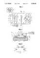
- FIG. 1is a top view of code array, i.e. a coded array with readout;
- FIG. 2is a section along line 2--2 of FIG. 1;
- FIG. 3is the electrical equivalent network of the coded arrays of FIGS. 1 and 2;
- FIG. 4is a simplified view similar to FIG. 1 of a variation in coded array
- FIG. 5is another variation of the coded array of FIG. 4;
- FIG. 6is still another variation of the coded array of FIG. 4;
- FIG. 7is a coded array similar to that of FIG. 1 with further variations in coded array;
- FIG. 8is a coded array similar to FIG. 1 but with variations
- FIG. 9is a cutaway of FIG. 1 showing a code array with a narrow bar electrode
- FIG. 10is a section along line 10--10 of FIG. 9;
- FIG. 11is similar to FIG. 10 but with a variation of shielding electrodes
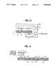
- FIG. 12shows the design of FIG. 11 in elevation as in FIG. 9;
- FIG. 13is a view similar to FIG. 2 of a variation of the reader.
- FIG. 14is a view along line 14--14 of FIG. 4 of a variation of the coded array
- FIG. 15is a view similar to FIG. 1 of a variation of the coding with associated reader.
- FIG. 16is a view similar to FIG. 15 of another variation of the coding.
- a card indicated generally at 1is designed as a bank access card such as an automatic teller card or debit card and bears a code array, i.e., a coded array, serving purposes the details of which are beyond the scope of this discussion, such as clearance for authorized personnel at entrances, for making cashless payments, etc.
- the card 1comprises an electrically non-conductive, planar substrate 2 which can be made of a plastic.
- a coded array of an electrically conductive material, for instance copper,is deposited on this substrate 2.
- the coded arrayconsists of a bar code in the form of conductive connectors 3 located at code sites A through G. As shown by FIG.
- the covering 4is preferably made of an opaque material so that, following the deposition of connectors 3, their arrangement no longer can be seen by the eye.
- the covering 4illustratively may be a layer of enamel or lacquer. For the sake of clarity, covering 4 is omitted from FIG. 1.
- the ends of the connectors 3are enlarged with respect to the rest of the connectors to act as coupling sites 5.
- the coupling sites 5are located precisely at the code sites A through G.
- a reader 6is movable above the card 1 in the direction of the arrow of FIG. 1 either manually or by any convenient mechanical device such as motion producing means 16. Since relative movement between the reader and the card is the essential factor, it is not important whether the card or the reader is moved. Thus, the card can be passed through a housing containing the reader.
- the reader 6is regarded as being movable and comprises two circular electrodes 7 on its lower side which, upon motion of the reader in the direction of the arrow of FIG. 1, arrive sequentially at and above the coupling sites 5.
- FIG. 3shows an electrical equivalent circuit of the structure of FIGS. 1 and 2. Together with the coupling sites 5, the electrodes 7 form capacitors and the connectors 3 form an ohmic resistance.
- An AC circuit including an AC generator 8 and a detector 9is present inside the reader 6. In the absence of some external electrical coupling to electrodes 7, this AC circuit is open between the ends of the circuit at electrodes 7.
- each connector 3 so loadedtherefore acts as a segment of the AC circuit and completes that part of the circuit which is in the reader and is denoted by 7, 8, 9, 7.
- the AC signal from the generator 8is steady-state and uninterrupted. Preferably, it is a high frequency AC, typically above 100 Khz. If now the reader 6 moves at a comparatively high speed, illustratively at 1 m/s above the coded array, and if the width (in the direction of motion) of each coupling site is 1 mm, then the capacitive coupling between the electrodes 7 and each coupling site 5 will exist for a time interval of about one millisecond. At a generator frequency of 1 Mhz there are about 1,000 AC periods during the time of coupling. Therefore the detector 9 is able to measure or sense the resulting current over a range of pure AC free of interference, that is, it will be unaffected by any transients.
- the reader 6moves along the array shown, then it will sense a current at the codes sites A, B, D, F and G but not at C and E.
- the code 1-1-0-1-0-1-1is the result.
- the essence of the connectors 3is that they link a particular pair of coupling sites 5. Such linkage need not be straight.
- the connector 3'is sinuous at the code site F. It serves the same purpose as the straight connectors 3 of the previous connections.
- part of the connector 3"is on the back side of the card, being provided with feedthroughs at sites 10 to the top side. This example is merely provided to indicate the many possible designs.
- the reader 6may be provided with an output line at its detector 9 to feed the detector signal to an analyzer 11 which may be external.
- a computercan advantageously be used to analyze the output signals produced by detector 9 and recognize the code.
- coded array shown in FIGS. 1 and 2can be read by the reader 6 whether a covering 4 is present or not.
- coded arraysare especially advantageous when they are provided with a covering 4 opaque to the human eye which thus cannot discern the code represented by the array.
- coded arrays without coveringmay also be used.
- An illustrative application of the code technique describedis process control for enameling motor vehicle fenders.
- a coded array as shown in FIGS. 1 and 2is mounted at a specific fender location and the paint primer layer of the fender serves as the electrically insulating substrate 2 on which the adequately electrically conductive coded array is deposited.
- Different fenderscan be identified by the coded arrays, for instance front, rear, left, right, or fenders for different models of the vehicle.
- the coded arrayis exposed before the final enameling. After this final enameling, the coded array is invisibly masked by the enamel which forms the equivalent to covering 4 of FIG. 2. Even after the enameling, the fender still can be identified by means of the coded array using a reader 6.
- Another illustrative exampleis an esthetic, expensive box holding an expensive perfume.
- a coded arrayis deposited on the cardboard which serves as the substrate. Then the entire box is lacquered in a high-grade manner, including the coded array. The coded array is then invisible from the outside and does not interfere with the esthetics of the box. Nevertheless, such boxes can be identified by means of their individual coded arrays, for instance when being monitored during marketing.
- the coupling sites 5 of FIG. 1are wider than the connectors 3 to achieve higher capacitance with the electrodes 7 shown here as plate electrodes. This feature is not required if the detector circuit used is sufficiently sensitive.
- FIG. 4shows a plain bar code (here as elsewhere, the opaque covering 4 shown in FIG. 1 has been omitted for clarity).
- the electrically conductive bars 12are elongated rectangles. Again the reader 6 is moved in the direction of the arrow and capacitively couples with the opposite end of the bars 12 as shown in FIG. 2.
- the code arraylacks two bars (dashed rectangles). This provides coded array information when reading this bar code.
- the code array described in relation to FIG. 4is positive, i.e., bars of electrically conductive material are present at the coded sites whereas only electrically non-conductive material is present at sites 13 where the bars are absent. However, it is also possible to encode in a negative manner. In that event the entire surface of the card is coated with an electrically conductive material which is removed from the sites equivalent to bars 12. If the reader 6 moves above such a coded array in the direction of the arrow, then it will ascertain a conductive connection between the electrodes everywhere except at the locations corresponding to bars 12 which lack conductive material.
- detector 9 of reader 6is designed in such a manner that it can quantitatively measure the electrical resistance R of the connector 3.
- the detector 9can be a simple AC ohmmeter. If in FIG. 4 widened bars 13 are provided (as shown by the dashed lines) instead of coding gaps, and these bars 13 are twice the width of bars 12, and therefore their ohmic resistance over their length is about half, then the reader 6 can sense and analyze this condition and thereby recognize the code.
- such a coded arraymay be printed with conducting ink. Double-thickness bars may be produced by double printing. Such coded arrays may be made very economically in one printing procedure. Suitable conducting inks, for instance containing carbon particles, are available commercially.
- FIG. 5shows a variation in which all bars are equally long and equally wide. However, bars 14 are interrupted by one break 15 in each.
- Such coded arraysmay be highly economical by preparing them in uncoded manner in the form of equal and continuous bars 12 and thereupon encoding them by introducing breaks 15 at the sites to be coded.
- the breaks 15may be made by mechanical scraping, etching or the like.
- FIG. 6is an embodiment again comprising the code of FIG. 4 with bars 12.
- a baris missing at two locations, so that encoding is achieved in a simple manner.
- the coded array of FIG. 6differs from that of FIG. 4 in that the bars 12 are joined at their lower ends in a comb-like manner to a bus 18.
- the readermay be made in two parts, namely a stationary part 6a which, during readout, couples with the bus 18 and a part 6b which is moved in the direction of the arrow precisely in the same way as the reader 6 is in FIG. 4, so that its electrode moves over the upper ends of the bars 12.
- the reader movable part 6bis moved across the coded array. This is a relative motion between the reader part and the coded array and this relative motion can be generated either by moving the movable reader part or the coded array.
- the reader 6may be moved if the card 1 is stationary or if the reader 6 is stationary, then the card 1 is moved.
- the relative motion between the card 1 and the movable reader 6bcan be obtained using a motor drive.
- a motor 60is affixed to the card 1 by a clamp 61 and drives a pinion 62 which engages and drives a gear rack 63 fastened to movable reader part 6b.
- Similar motor drivesalso can be provided in the array of FIG. 1 to produce relative motion between the reader 6 and the card 1.
- FIG. 7shows a further variation illustrating several such possibilities of the invention.
- the reader 6dis shown in top view and is in the form of record player with a centering pin 19, receiving a circular code disk 20 with central aperture.
- This code diskbears a coded array consisting of a central ring 21 from which bars 22 radiate outwardly at unequal angles forming a coded array.
- bars 22 providedare 45° apart or else, as indicated at two sites by dashes, are omitted to create a coded array.
- the code disk 20is rotatably driven by the reader 6d.
- a reading head 23comprises two adjacent electrodes (dashed circles) responding when coupling with neighboring bars 22, the current then passing between the coupling sites at the outer ends of the bars 22 through the annular bus 21.
- a reading head 24which couples the bars 22 at the radially outer and radially inner ends, by means of its two electrodes.
- the annular bus 21 connecting the inner ends of the barscan be omitted.
- coded arraysmay be used for the embodiment of FIG. 7.
- the barsfurthermore may be coded by making them various ohmic resistances, being of different widths or thicknesses.
- FIG. 8shows a coded array variation not in the form of a bar code but as a continuous, rectangular, electrically conducting surface array 26 read by a reader 9 which is moved in the manner of the embodiment of FIG. 1 in the direction of the arrow.
- the bottom electrode of reader 6 shown in FIG. 8everywhere couples to the same capacitance as it moves along its entire readout path above the first part of the substrate which has conductive area 26.
- the top electrode of reader 6 in FIG. 8sequentially moves above differently coded coupling sites 5b and 5c.
- the coupling sites 5bare identical. Illustratively they may be perforations made by stamping or by masking when the surface array 26 was deposited, and the electrode at the top of the reader 6 in FIG. 8 will couple capacitively with such perforations not at all or only weakly.
- the electrode of the reader 6 at the top in FIG. 9always sees the same unchanged capacitance which corresponds to that seen also by the reader electrode at the bottom in FIG. 8.
- the coupling site 5c of the embodiment of FIG. 8assumes a somewhat different design. In this case a ring 27 has been removed from around the actual, circular coupling site 5c whereby this coupling site no longer is electrically connected to the surface array 26. At this site again the reader 6 detects no current, or only a much weaker one.
- a segment 30 of the surface array 26 shown in FIG. 8 at the bottom rightis separated by a non-conductive band 31 from area 26. The point here is to show that even large-area segments can be separated. If reader 6 on its path from left to right in FIG. 8 comes to a point where its lower electrode is over the separated segment 30, it no longer can detect a current and therefore no more coding can be ascertained in this part of the card 1. This feature may be used as added coding.
- the simplest coded arraysare bar codes.
- electrode arrayssuch as are described in relation to FIGS. 9 through 12 are advantageously used.
- FIGS. 9 and 10are top plan and sectional side views (corresponding to FIGS. 1 and 2) of a reader 6e for reading a coded substrate wherein the coding is formed by bars 12. Only one electrode 7e is shown which is meant to couple with the coupling sites at the upper ends of the conducting bars 12. Again, the reader 6e is moved so as to read in the direction of the arrow.
- the elctrode 7eis made rod-like, narrow and parallel to the bars 12 in order to increase the spatial resolution of the electrode 7e. As shown by the Figures, electrode 7e also can couple on a large area, that is with large capacitance, with the bars 12, while nevertheless coupling only with the particular bar underneath, not with the adjacent one.
- FIG. 11shows a reader 6f in a view similar to FIG. 10. It will be noted that with respect to the readout movement direction indicated by the arrow, shielding electrodes 28 are present in front and behind the rod-like electrode 7f. These shielding electrodes are grounded. As shown in top view in FIG. 12, shielding electrodes 28 in front and behind the electrode 7f as seen in the readout direction may be hoined together at the ends so that they form a shielding window enclosing the electrode 7f or also both electrodes of the reader 6f.
- the shielding electrodes 28capacitively ground the bars 12 below them. Only one bar 12 located between the shielding electrodes is not capacitively grounded in this manner and, by means of capacitive coupling to electrode 7f, may accept a current from it.
- such a spatially highly resolving electrode arrayalso may be used in ascertaining the code by means of the width of the bars without having to compute its resistance. For instance as regards the coded array of FIG. 4 with bars 12 and 13 of different widths, a constant speed of advance of the reader 6 allows determining how long the electrodes are moving over each particular bar in order to use their widths as coding information.
- the coding arrayalways has been coupled capacitively from the top by means of electrodes.
- the substrate 2may be made relatively thick and dimensionally stable.
- the coded arrayalso may be affixed to the surface of a bulky object.
- readoutmay be implemented from both sides, that is, from the top side and from the bottom side of the card, i.e., by electrodes passing along the two major faces of the card or other substrate, as shown by FIG. 13. In that case the substrate 2 is preferably thinner. Otherwise the card 1 corresponds to the embodiment of FIG. 2.
- a reader 6ghas electrodes 7g which, corresponding to the embodiment of FIG. 1, couple with the two ends of code bars 3. One electrode, however, is coupling from the top side and the other from the bottom side.
- readoutmay be carried out selectively from the top or from the bottom.
- FIG. 14shows another variation of the invention as a section along line 14--14 of FIG. 4.
- the bars 12 and 13 of the coded arrayare at different depths, they are mounted on different sides (top and bottom) of a thin substrate 2 covered on opposite sides by coverings 4 and 4'.
- the reader 6may be designed as discussed in relation to FIGS. 1 and 2 and performs its readout by means of electrodes 7 as it is moved relatively in the direction of the arrow.
- FIG. 15shows a variation wherein the coded array comprises two rows of coupling sites 5 of which only a few (depending on the code) are pairwise linked by diagonal connections 3. As shown in FIG. 15, the connections 3 are oblique to the readout direction shown by the arrow. The electrodes 7h of a reader 6h are correspondingly laterally offset. If the attempt is made to read the shown coded array with the reader 6 of FIG. 1, failure would result. In this or similar manner, reaout may be made more difficult in order to improve reliability against forgery.
- FIG. 16shows another variation of the coding, with simple bars 12 and a coded bar 13' in the form of an I-bar.
- a reader 6icomprises two electrodes 7i mounted sequentially in the direction of readout motion in order to read the bars 12 and 13'. The reader 6i moves in the direction of the arrow above the shown coded array. When it arrives at and above the first bar 12, then that bar is detected at each end only by one electrode 7i. When on the other hand the reader 6i passes above the coded bar 13', then both electrodes will be coupling at each end of the bar 13', whereby the coupling capacitance is doubled. This is sensed as a code by the detector 9.
Landscapes
- Engineering & Computer Science (AREA)
- Physics & Mathematics (AREA)
- General Physics & Mathematics (AREA)
- Theoretical Computer Science (AREA)
- Artificial Intelligence (AREA)
- Computer Vision & Pattern Recognition (AREA)
- Measurement Of Length, Angles, Or The Like Using Electric Or Magnetic Means (AREA)
- Credit Cards Or The Like (AREA)
Abstract
Description
Claims (5)
Applications Claiming Priority (2)
| Application Number | Priority Date | Filing Date | Title |
|---|---|---|---|
| DE3933542ADE3933542A1 (en) | 1989-10-07 | 1989-10-07 | CODE ARRANGEMENT AND DEVICES FOR READING AND CODING THE SAME |
| DE3933542 | 1989-10-07 |
Publications (1)
| Publication Number | Publication Date |
|---|---|
| US5159181Atrue US5159181A (en) | 1992-10-27 |
Family
ID=6391029
Family Applications (1)
| Application Number | Title | Priority Date | Filing Date |
|---|---|---|---|
| US07/592,493Expired - LifetimeUS5159181A (en) | 1989-10-07 | 1990-10-04 | Capacitive code reader with interelectrode shielding |
Country Status (4)
| Country | Link |
|---|---|
| US (1) | US5159181A (en) |
| EP (2) | EP0422481A3 (en) |
| JP (2) | JPH03131996A (en) |
| DE (1) | DE3933542A1 (en) |
Cited By (30)
| Publication number | Priority date | Publication date | Assignee | Title |
|---|---|---|---|---|
| US5471040A (en)* | 1993-11-15 | 1995-11-28 | May; George | Capacitive data card system |
| US5757521A (en)* | 1995-05-11 | 1998-05-26 | Advanced Deposition Technologies, Inc. | Pattern metallized optical varying security devices |
| US5949060A (en)* | 1996-11-01 | 1999-09-07 | Coincard International, Inc. | High security capacitive card system |
| US6362972B1 (en) | 2000-04-13 | 2002-03-26 | Molex Incorporated | Contactless interconnection system |
| US6547140B2 (en)* | 2000-11-29 | 2003-04-15 | Xerox Corporation | Microwave barcode reader using dipole antenna |
| US6612852B1 (en) | 2000-04-13 | 2003-09-02 | Molex Incorporated | Contactless interconnection system |
| US20040076220A1 (en)* | 2002-10-21 | 2004-04-22 | Tseng Daniel C.M. | Method for identifying the classification of temperature detection components of electronic thermometers |
| WO2005008574A1 (en)* | 2003-07-17 | 2005-01-27 | Avantone Oy | Method for detecting objects and a system for solving content of a symbol |
| US20050156318A1 (en)* | 2004-01-15 | 2005-07-21 | Douglas Joel S. | Security marking and security mark |
| US20060012944A1 (en)* | 2002-10-31 | 2006-01-19 | Mamigonians Hrand M | Mechanically operable electrical device |
| US20060131411A1 (en)* | 2004-12-20 | 2006-06-22 | Heikki Huomo | Sensor head of a code reader |
| US20060138233A1 (en)* | 2004-12-29 | 2006-06-29 | Antti Kemppainen | Code reader |
| US20070012786A1 (en)* | 2003-07-17 | 2007-01-18 | Honda Motor Co., Ltd. | Ic card and information storage/transmitter |
| GB2436634A (en)* | 2006-03-28 | 2007-10-03 | Avantone Oy | Machine readable code system |
| US20090114726A1 (en)* | 2006-05-11 | 2009-05-07 | Zhivko Zhelev | Method and device for protection and control of originality of products and their components and electronically readable certificate thereof |
| GB2455779A (en)* | 2007-12-21 | 2009-06-24 | Novalia Ltd | Reader and electronic tag with conductive tracks having narrow and wide sections |
| US20090309303A1 (en)* | 2008-06-16 | 2009-12-17 | Pure Imagination | Method and system for identifying a game piece |
| CN101790737A (en)* | 2008-05-15 | 2010-07-28 | 芬兰技术研究中心 | Method and device for identifying electronic codes |
| US20100206952A1 (en)* | 2007-09-14 | 2010-08-19 | Tokyo Mechatronics Co., Limited | Capacitive data body and data reading device thereof |
| AU2010246371B2 (en)* | 2008-11-04 | 2011-01-27 | Touchcode Technologies, LLC | Identification system and applications |
| US20110155806A1 (en)* | 2007-06-26 | 2011-06-30 | Thoralt Franz | Method and data carrier for storing and reading a data code |
| US8098240B2 (en) | 2008-06-20 | 2012-01-17 | Mattel, Inc. | Capacitive touchpad and toy incorporating the same |
| US20130112755A1 (en)* | 2009-12-16 | 2013-05-09 | Teknologian Tutkimuskeskus Vtt | Programmable printed electric code, method of manufacturing the same and a programming device |
| US8608079B2 (en) | 2006-03-20 | 2013-12-17 | Novo Nordisk A/S | Contact free reading of cartridge identification codes |
| CN105938567A (en)* | 2016-05-19 | 2016-09-14 | 深圳市希顿科技有限公司 | Near-field identification device and communication method thereof |
| US9835434B1 (en)* | 2014-10-13 | 2017-12-05 | Google Inc. | Home automation input interfaces based on a capacitive touchscreen for detecting patterns of conductive ink |
| US9950117B2 (en) | 2009-02-13 | 2018-04-24 | Novo Nordisk A/S | Medical device and cartridge |
| US9977547B1 (en) | 2014-10-13 | 2018-05-22 | Google Llc | Home automation input interfaces based on a capacitive touchscreen for detecting patterns of conductive ink |
| US10551218B2 (en) | 2014-05-23 | 2020-02-04 | Pragmatic Printing Limited | Capacitive detection, energy transfer, and/or data transfer system |
| US11088093B1 (en)* | 2020-05-28 | 2021-08-10 | X-Celeprint Limited | Micro-component anti-stiction structures |
Families Citing this family (26)
| Publication number | Priority date | Publication date | Assignee | Title |
|---|---|---|---|---|
| DE4224371A1 (en)* | 1992-07-23 | 1994-01-27 | Thomson Brandt Gmbh | Bar=code partic. with programme information on video cassette - has EEPROM chip storing programme data built into cassette and has connection to sections of bar=code contacts accessed by bar=code reader |
| EP0653082B1 (en)* | 1992-07-23 | 1997-10-01 | Deutsche Thomson-Brandt Gmbh | Cassette or diskette with contacts in barcode shape |
| BR9401059A (en)* | 1994-05-12 | 1995-12-05 | Brasilia Telecom | Supplemental encoding on debit cards and reading process |
| FR2721421B1 (en)* | 1994-06-15 | 1996-08-30 | Solaic Sa | Method and installation for the adjustment of a contactless electronic card. |
| CN1210603A (en) | 1996-02-02 | 1999-03-10 | 株式会社东京机械电子 | Capacitive data card and reader thereof |
| US6663602B2 (en) | 2000-06-16 | 2003-12-16 | Novo Nordisk A/S | Injection device |
| DE10304846A1 (en)* | 2002-08-20 | 2004-08-19 | Anitra Medienprojekte Gmbh | Machine readable barcode patterns |
| ATE444090T1 (en) | 2004-10-21 | 2009-10-15 | Novo Nordisk As | SELECTION MECHANISM FOR A ROTARY PIN |
| DE102005002150A1 (en)* | 2005-01-17 | 2006-07-20 | Printed Systems Gmbh | Memory element with printed line sequences of conductive material printed on flexible substrate, with each line either conductive or non conductive due to interruption |
| DE102005042089A1 (en)* | 2005-09-05 | 2007-03-08 | Printed Systems Gmbh | System for storing and reading information, has data storing medium linked with reading unit such that storage electrode, dielectric and evaluation electrode form condenser |
| CN101405044B (en) | 2006-03-20 | 2013-10-16 | 诺沃-诺迪斯克有限公司 | Determination of position of injection needle |
| ATE458517T1 (en) | 2006-05-16 | 2010-03-15 | Novo Nordisk As | TRANSMISSION MECHANISM FOR AN INJECTION DEVICE |
| JP5253387B2 (en) | 2006-05-18 | 2013-07-31 | ノボ・ノルデイスク・エー/エス | Injection device with mode locking means |
| DE102006039926A1 (en)* | 2006-08-25 | 2008-02-28 | Printed Systems Gmbh | household appliance |
| US8052655B2 (en) | 2006-09-29 | 2011-11-08 | Novo Nordisk A/S | Injection device with electronic detecting means |
| DE102006048401A1 (en)* | 2006-10-12 | 2008-04-17 | Printed Systems Gmbh | System and method for storing and reading information |
| DE102006056562A1 (en)* | 2006-11-30 | 2008-06-05 | Printed Systems Gmbh | Prepaid card and procedure for making an electronic payment |
| US9108006B2 (en) | 2007-08-17 | 2015-08-18 | Novo Nordisk A/S | Medical device with value sensor |
| GB0717502D0 (en)* | 2007-09-08 | 2007-10-17 | Unibyte Ltd | Identification and recordal apparatus |
| CA2707820A1 (en) | 2007-12-31 | 2009-07-09 | Novo Nordisk A/S | Electronically monitored injection device |
| EP2088532A1 (en)* | 2008-02-06 | 2009-08-12 | Sascha Voigt | Flat data carrier |
| JP2011154453A (en)* | 2010-01-26 | 2011-08-11 | Riso Kagaku Corp | Recorded information reading apparatus and method of reading recorded information |
| JP6069351B2 (en) | 2011-12-29 | 2017-02-01 | ノボ・ノルデイスク・エー/エス | Torsion spring type automatic syringe with dial-up / dial-down administration mechanism |
| EP3355246B1 (en)* | 2017-01-31 | 2022-08-17 | Prismade Labs GmbH | Method for producing a time-dependant signal on a capacitive area sensor and a method for identifying a card-like object, and a card-like object and use thereof |
| MX2019009077A (en) | 2017-01-31 | 2019-11-12 | Prismade Labs Gmbh | Method for generating a time-dependent signal on a capacitive surface sensor and method for identifying a card-like object, and card-like object and use thereof. |
| EP3355234A1 (en)* | 2017-01-31 | 2018-08-01 | Prismade Labs GmbH | Device and its use for the generation of a time-dependent signal on a capacitive surface sensor, and an electrically conductive structure for such a device |
Citations (9)
| Publication number | Priority date | Publication date | Assignee | Title |
|---|---|---|---|---|
| US3218635A (en)* | 1960-10-07 | 1965-11-16 | United Aircraft Corp | Capacitive encoder device |
| US3519802A (en)* | 1968-11-27 | 1970-07-07 | Securadyne Ltd | Cards employing capacitor sensing of encoded data |
| US3699311A (en)* | 1971-01-25 | 1972-10-17 | Remvac Systems Corp | Coded card and reader therefor |
| US3719804A (en)* | 1971-03-26 | 1973-03-06 | Int Computers Ltd | Permanent information store |
| DE2252046A1 (en)* | 1972-10-24 | 1974-05-02 | Remvac Systems Corp | CARD WITH ENCRYPTED INFORMATION BITS AND ASSOCIATED READER |
| US4255652A (en)* | 1979-01-31 | 1981-03-10 | Coulter Systems Corporation | High speed electrically responsive indicia detecting apparatus and method |
| US4355300A (en)* | 1980-02-14 | 1982-10-19 | Coulter Systems Corporation | Indicia recognition apparatus |
| US4587410A (en)* | 1984-04-09 | 1986-05-06 | Milnes Arthur G | Capacitive card and reader parking system |
| US4888475A (en)* | 1986-06-18 | 1989-12-19 | Gerhard Rosorius | Thermally readable encoding and activation thereof |
Family Cites Families (6)
| Publication number | Priority date | Publication date | Assignee | Title |
|---|---|---|---|---|
| US3716701A (en)* | 1970-11-09 | 1973-02-13 | D Cohen | Encoded data card system |
| DE2812388C2 (en)* | 1978-03-21 | 1982-06-24 | Jürgen Ing.(grad.) 8019 Ebersberg Machate | Device for capacitive scanning of card-shaped data carriers |
| DE3236373A1 (en)* | 1982-10-01 | 1984-04-05 | Brown, Boveri & Cie Ag, 6800 Mannheim | Security paper |
| FI74358C (en)* | 1983-08-11 | 1988-01-11 | Aspo Oy | KAPASITIV LAESMETOD FOER KODKORT OCH LAESANORDNING FOER FOERVERKLIGANDE AV FOERFARANDET. |
| AT386159B (en)* | 1985-10-11 | 1988-07-11 | Oesterr Nationalbank | METHOD AND DEVICE FOR PRODUCING REALITY (CODING) CHARACTERISTICS ON SECURITIES |
| FR2616948A1 (en)* | 1987-06-16 | 1988-12-23 | Cga Hbs | Magnetic head for magnetic track |
- 1989
- 1989-10-07DEDE3933542Apatent/DE3933542A1/ennot_activeCeased
- 1990
- 1990-10-02EPEP19900118845patent/EP0422481A3/ennot_activeWithdrawn
- 1990-10-02EPEP19900118846patent/EP0422482A3/ennot_activeWithdrawn
- 1990-10-04USUS07/592,493patent/US5159181A/ennot_activeExpired - Lifetime
- 1990-10-06JPJP2267567Apatent/JPH03131996A/enactivePending
- 1990-10-06JPJP2267566Apatent/JP2781811B2/ennot_activeExpired - Fee Related
Patent Citations (9)
| Publication number | Priority date | Publication date | Assignee | Title |
|---|---|---|---|---|
| US3218635A (en)* | 1960-10-07 | 1965-11-16 | United Aircraft Corp | Capacitive encoder device |
| US3519802A (en)* | 1968-11-27 | 1970-07-07 | Securadyne Ltd | Cards employing capacitor sensing of encoded data |
| US3699311A (en)* | 1971-01-25 | 1972-10-17 | Remvac Systems Corp | Coded card and reader therefor |
| US3719804A (en)* | 1971-03-26 | 1973-03-06 | Int Computers Ltd | Permanent information store |
| DE2252046A1 (en)* | 1972-10-24 | 1974-05-02 | Remvac Systems Corp | CARD WITH ENCRYPTED INFORMATION BITS AND ASSOCIATED READER |
| US4255652A (en)* | 1979-01-31 | 1981-03-10 | Coulter Systems Corporation | High speed electrically responsive indicia detecting apparatus and method |
| US4355300A (en)* | 1980-02-14 | 1982-10-19 | Coulter Systems Corporation | Indicia recognition apparatus |
| US4587410A (en)* | 1984-04-09 | 1986-05-06 | Milnes Arthur G | Capacitive card and reader parking system |
| US4888475A (en)* | 1986-06-18 | 1989-12-19 | Gerhard Rosorius | Thermally readable encoding and activation thereof |
Cited By (48)
| Publication number | Priority date | Publication date | Assignee | Title |
|---|---|---|---|---|
| US5471040A (en)* | 1993-11-15 | 1995-11-28 | May; George | Capacitive data card system |
| US5757521A (en)* | 1995-05-11 | 1998-05-26 | Advanced Deposition Technologies, Inc. | Pattern metallized optical varying security devices |
| US5949060A (en)* | 1996-11-01 | 1999-09-07 | Coincard International, Inc. | High security capacitive card system |
| US6362972B1 (en) | 2000-04-13 | 2002-03-26 | Molex Incorporated | Contactless interconnection system |
| US6612852B1 (en) | 2000-04-13 | 2003-09-02 | Molex Incorporated | Contactless interconnection system |
| US6547140B2 (en)* | 2000-11-29 | 2003-04-15 | Xerox Corporation | Microwave barcode reader using dipole antenna |
| US20040076220A1 (en)* | 2002-10-21 | 2004-04-22 | Tseng Daniel C.M. | Method for identifying the classification of temperature detection components of electronic thermometers |
| US20060012944A1 (en)* | 2002-10-31 | 2006-01-19 | Mamigonians Hrand M | Mechanically operable electrical device |
| WO2005008574A1 (en)* | 2003-07-17 | 2005-01-27 | Avantone Oy | Method for detecting objects and a system for solving content of a symbol |
| US20070084934A1 (en)* | 2003-07-17 | 2007-04-19 | Avantone Oy | Method for detecting objects and a system for solving content of a symbol |
| US20070012786A1 (en)* | 2003-07-17 | 2007-01-18 | Honda Motor Co., Ltd. | Ic card and information storage/transmitter |
| US20050156318A1 (en)* | 2004-01-15 | 2005-07-21 | Douglas Joel S. | Security marking and security mark |
| US7513437B2 (en)* | 2004-01-15 | 2009-04-07 | Douglas Joel S | Security marking and security mark |
| US20080135629A1 (en)* | 2004-01-15 | 2008-06-12 | Douglas Joel S | Security marking and security mark |
| US20060131411A1 (en)* | 2004-12-20 | 2006-06-22 | Heikki Huomo | Sensor head of a code reader |
| EP1677229A1 (en) | 2004-12-29 | 2006-07-05 | Avantone Oy | Code reader |
| US7490772B2 (en) | 2004-12-29 | 2009-02-17 | Nokia Corporation | Code reader |
| US20060138233A1 (en)* | 2004-12-29 | 2006-06-29 | Antti Kemppainen | Code reader |
| US8608079B2 (en) | 2006-03-20 | 2013-12-17 | Novo Nordisk A/S | Contact free reading of cartridge identification codes |
| GB2436634A (en)* | 2006-03-28 | 2007-10-03 | Avantone Oy | Machine readable code system |
| WO2007110485A1 (en)* | 2006-03-28 | 2007-10-04 | Nokia Corporation | Machine readable code system |
| US20090114726A1 (en)* | 2006-05-11 | 2009-05-07 | Zhivko Zhelev | Method and device for protection and control of originality of products and their components and electronically readable certificate thereof |
| US20110155806A1 (en)* | 2007-06-26 | 2011-06-30 | Thoralt Franz | Method and data carrier for storing and reading a data code |
| US20100206952A1 (en)* | 2007-09-14 | 2010-08-19 | Tokyo Mechatronics Co., Limited | Capacitive data body and data reading device thereof |
| EP2192529A4 (en)* | 2007-09-14 | 2011-05-04 | Tokyo Mechatronics Co Ltd | Capacitive data body and data reader for reading capacitive data |
| US8434684B2 (en)* | 2007-09-14 | 2013-05-07 | Tokyo Mechatronics Co., Limited | Capacitive data body and data reading device thereof |
| US20110025466A1 (en)* | 2007-12-21 | 2011-02-03 | Novalia Ltd. | Electronic tag |
| GB2455779A (en)* | 2007-12-21 | 2009-06-24 | Novalia Ltd | Reader and electronic tag with conductive tracks having narrow and wide sections |
| CN101790737A (en)* | 2008-05-15 | 2010-07-28 | 芬兰技术研究中心 | Method and device for identifying electronic codes |
| US8955751B2 (en) | 2008-05-15 | 2015-02-17 | Nicanti Oy | Method and device for identifying an electronic code |
| US20110101098A1 (en)* | 2008-05-15 | 2011-05-05 | Seppae Heikki | Method and device for identifying an electronic code |
| CN101790737B (en)* | 2008-05-15 | 2014-05-28 | 芬兰技术研究中心 | Method and device for identifying an electronic code |
| US20090309303A1 (en)* | 2008-06-16 | 2009-12-17 | Pure Imagination | Method and system for identifying a game piece |
| US8104688B2 (en)* | 2008-06-16 | 2012-01-31 | Michael Wallace | Method and system for identifying a game piece |
| US8098240B2 (en) | 2008-06-20 | 2012-01-17 | Mattel, Inc. | Capacitive touchpad and toy incorporating the same |
| US8400426B2 (en) | 2008-06-20 | 2013-03-19 | Mattel, Inc. | Capacitive touchpad and toy incorporating the same |
| US8622307B2 (en) | 2008-11-04 | 2014-01-07 | Printechnologies Gmbh | Identification system and applications |
| AU2010246371B2 (en)* | 2008-11-04 | 2011-01-27 | Touchcode Technologies, LLC | Identification system and applications |
| US9950117B2 (en) | 2009-02-13 | 2018-04-24 | Novo Nordisk A/S | Medical device and cartridge |
| US20130112755A1 (en)* | 2009-12-16 | 2013-05-09 | Teknologian Tutkimuskeskus Vtt | Programmable printed electric code, method of manufacturing the same and a programming device |
| US10551218B2 (en) | 2014-05-23 | 2020-02-04 | Pragmatic Printing Limited | Capacitive detection, energy transfer, and/or data transfer system |
| US11255701B2 (en) | 2014-05-23 | 2022-02-22 | Pragmatic Printing Limited | Capacitive detection, energy transfer, and/or data transfer system |
| US9835434B1 (en)* | 2014-10-13 | 2017-12-05 | Google Inc. | Home automation input interfaces based on a capacitive touchscreen for detecting patterns of conductive ink |
| US9977547B1 (en) | 2014-10-13 | 2018-05-22 | Google Llc | Home automation input interfaces based on a capacitive touchscreen for detecting patterns of conductive ink |
| CN105938567A (en)* | 2016-05-19 | 2016-09-14 | 深圳市希顿科技有限公司 | Near-field identification device and communication method thereof |
| CN105938567B (en)* | 2016-05-19 | 2019-01-04 | 深圳市希顿科技有限公司 | A kind of near field identification device and its communication means |
| US11088093B1 (en)* | 2020-05-28 | 2021-08-10 | X-Celeprint Limited | Micro-component anti-stiction structures |
| US11670603B2 (en) | 2020-05-28 | 2023-06-06 | X-Celeprint Limited | Micro-component anti-stiction structures |
Also Published As
| Publication number | Publication date |
|---|---|
| JP2781811B2 (en) | 1998-07-30 |
| EP0422481A2 (en) | 1991-04-17 |
| DE3933542A1 (en) | 1991-04-18 |
| JPH03126184A (en) | 1991-05-29 |
| EP0422482A2 (en) | 1991-04-17 |
| EP0422482A3 (en) | 1991-08-07 |
| JPH03131996A (en) | 1991-06-05 |
| EP0422481A3 (en) | 1991-07-31 |
Similar Documents
| Publication | Publication Date | Title |
|---|---|---|
| US5159181A (en) | Capacitive code reader with interelectrode shielding | |
| US4791283A (en) | Transaction card magnetic stripe emulator | |
| US4394773A (en) | Fingerprint sensor | |
| JP3007714B2 (en) | Fingerprint detection device | |
| US7110577B1 (en) | Method and apparatus for measuring structures in a fingerprint | |
| KR920006327B1 (en) | System for sensing spacial coordinates | |
| EP0853795B1 (en) | In a fingerprint recognizing apparatus detector for recognizing the living character of a finger | |
| EP0790479B1 (en) | Capacitive distance sensor, particularly for acquiring fingerprints | |
| CA1106466A (en) | Device for checking metal pieces, particularly coins | |
| JPH07503336A (en) | Horizontal magnetoresistive head device and method for magnetic data detection | |
| US3869082A (en) | Data storage and retrieval system | |
| GB2079017A (en) | Sensing record cards by electric induction | |
| JP2935454B2 (en) | Photoelectric position measuring device | |
| US4585930A (en) | Slotless magnetic card reader | |
| US6330939B1 (en) | Device and method for determining the authenticity of documents | |
| EP2223263A1 (en) | Electronic tag | |
| US3470359A (en) | Anti-counterfeit document | |
| GB1604087A (en) | Device and method for detecting magnetic fields and a method of manufacturing the device | |
| AU630526B2 (en) | Card fraud detector | |
| CA1041662A (en) | Apparatus for the storage and reading of data combined from binary numbers | |
| CA1228134A (en) | Process and apparatus for detection of electrically conducting material | |
| US4857828A (en) | Method and apparatus for detecting presence of objects | |
| JPH01254827A (en) | Pressure sensing plate for detecting uneven image pressure distribution | |
| GB2062327A (en) | A Capacitive Coin Detector | |
| US3716701A (en) | Encoded data card system |
Legal Events
| Date | Code | Title | Description |
|---|---|---|---|
| AS | Assignment | Owner name:KG CATTS GESELLSCHAFT FUR ERKENNUNGS-& SICHERHEITS Free format text:ASSIGNMENT OF ASSIGNORS INTEREST.;ASSIGNORS:DIEKMANN, RAINER;BARTELS, HOLGER;REEL/FRAME:005513/0514 Effective date:19901102 | |
| STCF | Information on status: patent grant | Free format text:PATENTED CASE | |
| FEPP | Fee payment procedure | Free format text:PAYOR NUMBER ASSIGNED (ORIGINAL EVENT CODE: ASPN); ENTITY STATUS OF PATENT OWNER: SMALL ENTITY | |
| FPAY | Fee payment | Year of fee payment:4 | |
| REMI | Maintenance fee reminder mailed | ||
| FPAY | Fee payment | Year of fee payment:8 | |
| SULP | Surcharge for late payment | Year of fee payment:7 | |
| FEPP | Fee payment procedure | Free format text:PAYER NUMBER DE-ASSIGNED (ORIGINAL EVENT CODE: RMPN); ENTITY STATUS OF PATENT OWNER: SMALL ENTITY Free format text:PAYOR NUMBER ASSIGNED (ORIGINAL EVENT CODE: ASPN); ENTITY STATUS OF PATENT OWNER: SMALL ENTITY | |
| FPAY | Fee payment | Year of fee payment:12 | |
| FEPP | Fee payment procedure | Free format text:PAYER NUMBER DE-ASSIGNED (ORIGINAL EVENT CODE: RMPN); ENTITY STATUS OF PATENT OWNER: SMALL ENTITY Free format text:PAYOR NUMBER ASSIGNED (ORIGINAL EVENT CODE: ASPN); ENTITY STATUS OF PATENT OWNER: SMALL ENTITY |