US5156863A - Continuous embossing belt - Google Patents
Continuous embossing beltDownload PDFInfo
- Publication number
- US5156863A US5156863AUS06/903,226US90322686AUS5156863AUS 5156863 AUS5156863 AUS 5156863AUS 90322686 AUS90322686 AUS 90322686AUS 5156863 AUS5156863 AUS 5156863A
- Authority
- US
- United States
- Prior art keywords
- pattern
- embossing tool
- embossing
- tool set
- tool
- Prior art date
- Legal status (The legal status is an assumption and is not a legal conclusion. Google has not performed a legal analysis and makes no representation as to the accuracy of the status listed.)
- Expired - Fee Related
Links
- 238000004049embossingMethods0.000titleclaimsabstractdescription55
- 239000000463materialSubstances0.000claimsabstractdescription20
- 238000005323electroformingMethods0.000claimsdescription8
- 238000005259measurementMethods0.000claims1
- 238000000034methodMethods0.000description28
- PXHVJJICTQNCMI-UHFFFAOYSA-NNickelChemical compound[Ni]PXHVJJICTQNCMI-UHFFFAOYSA-N0.000description18
- 229910052759nickelInorganic materials0.000description9
- 239000007787solidSubstances0.000description9
- 238000005520cutting processMethods0.000description8
- 230000003287optical effectEffects0.000description8
- 238000000926separation methodMethods0.000description6
- 238000004519manufacturing processMethods0.000description5
- 238000004070electrodepositionMethods0.000description4
- VEQPNABPJHWNSG-UHFFFAOYSA-NNickel(2+)Chemical compound[Ni+2]VEQPNABPJHWNSG-UHFFFAOYSA-N0.000description3
- 229910001453nickel ionInorganic materials0.000description3
- 239000004033plasticSubstances0.000description3
- 239000000758substrateSubstances0.000description3
- 239000004593EpoxySubstances0.000description2
- 238000005266castingMethods0.000description2
- 238000000748compression mouldingMethods0.000description2
- 206010016256fatigueDiseases0.000description2
- 229910052751metalInorganic materials0.000description2
- 239000002184metalSubstances0.000description2
- 238000007747platingMethods0.000description2
- 229920000728polyesterPolymers0.000description2
- 230000003362replicative effectEffects0.000description2
- 230000035900sweatingEffects0.000description2
- 229920001169thermoplasticPolymers0.000description2
- 239000004416thermosoftening plasticSubstances0.000description2
- 229920002799BoPETPolymers0.000description1
- RYGMFSIKBFXOCR-UHFFFAOYSA-NCopperChemical compound[Cu]RYGMFSIKBFXOCR-UHFFFAOYSA-N0.000description1
- 239000005041Mylar™Substances0.000description1
- 230000004075alterationEffects0.000description1
- 229910052782aluminiumInorganic materials0.000description1
- XAGFODPZIPBFFR-UHFFFAOYSA-NaluminiumChemical compound[Al]XAGFODPZIPBFFR-UHFFFAOYSA-N0.000description1
- 230000015572biosynthetic processEffects0.000description1
- 238000010276constructionMethods0.000description1
- 229910052802copperInorganic materials0.000description1
- 239000010949copperSubstances0.000description1
- 230000007812deficiencyEffects0.000description1
- 229910003460diamondInorganic materials0.000description1
- 239000010432diamondSubstances0.000description1
- 230000000694effectsEffects0.000description1
- 238000005755formation reactionMethods0.000description1
- 230000002452interceptive effectEffects0.000description1
- 238000005272metallurgyMethods0.000description1
- 239000012811non-conductive materialSubstances0.000description1
- 238000003825pressingMethods0.000description1
- 230000000750progressive effectEffects0.000description1
- 230000001681protective effectEffects0.000description1
- 230000010076replicationEffects0.000description1
- 238000006467substitution reactionMethods0.000description1
Images


Classifications
- B—PERFORMING OPERATIONS; TRANSPORTING
- B29—WORKING OF PLASTICS; WORKING OF SUBSTANCES IN A PLASTIC STATE IN GENERAL
- B29C—SHAPING OR JOINING OF PLASTICS; SHAPING OF MATERIAL IN A PLASTIC STATE, NOT OTHERWISE PROVIDED FOR; AFTER-TREATMENT OF THE SHAPED PRODUCTS, e.g. REPAIRING
- B29C59/00—Surface shaping of articles, e.g. embossing; Apparatus therefor
- B29C59/02—Surface shaping of articles, e.g. embossing; Apparatus therefor by mechanical means, e.g. pressing
- B29C59/04—Surface shaping of articles, e.g. embossing; Apparatus therefor by mechanical means, e.g. pressing using rollers or endless belts
- B—PERFORMING OPERATIONS; TRANSPORTING
- B23—MACHINE TOOLS; METAL-WORKING NOT OTHERWISE PROVIDED FOR
- B23P—METAL-WORKING NOT OTHERWISE PROVIDED FOR; COMBINED OPERATIONS; UNIVERSAL MACHINE TOOLS
- B23P15/00—Making specific metal objects by operations not covered by a single other subclass or a group in this subclass
- B23P15/24—Making specific metal objects by operations not covered by a single other subclass or a group in this subclass dies
- B—PERFORMING OPERATIONS; TRANSPORTING
- B26—HAND CUTTING TOOLS; CUTTING; SEVERING
- B26F—PERFORATING; PUNCHING; CUTTING-OUT; STAMPING-OUT; SEVERING BY MEANS OTHER THAN CUTTING
- B26F1/00—Perforating; Punching; Cutting-out; Stamping-out; Apparatus therefor
- B26F1/38—Cutting-out; Stamping-out
- B26F1/44—Cutters therefor; Dies therefor
- B—PERFORMING OPERATIONS; TRANSPORTING
- B29—WORKING OF PLASTICS; WORKING OF SUBSTANCES IN A PLASTIC STATE IN GENERAL
- B29C—SHAPING OR JOINING OF PLASTICS; SHAPING OF MATERIAL IN A PLASTIC STATE, NOT OTHERWISE PROVIDED FOR; AFTER-TREATMENT OF THE SHAPED PRODUCTS, e.g. REPAIRING
- B29C33/00—Moulds or cores; Details thereof or accessories therefor
- B29C33/38—Moulds or cores; Details thereof or accessories therefor characterised by the material or the manufacturing process
- B29C33/3842—Manufacturing moulds, e.g. shaping the mould surface by machining
- B29C33/3857—Manufacturing moulds, e.g. shaping the mould surface by machining by making impressions of one or more parts of models, e.g. shaped articles and including possible subsequent assembly of the parts
- B—PERFORMING OPERATIONS; TRANSPORTING
- B29—WORKING OF PLASTICS; WORKING OF SUBSTANCES IN A PLASTIC STATE IN GENERAL
- B29C—SHAPING OR JOINING OF PLASTICS; SHAPING OF MATERIAL IN A PLASTIC STATE, NOT OTHERWISE PROVIDED FOR; AFTER-TREATMENT OF THE SHAPED PRODUCTS, e.g. REPAIRING
- B29C33/00—Moulds or cores; Details thereof or accessories therefor
- B29C33/42—Moulds or cores; Details thereof or accessories therefor characterised by the shape of the moulding surface, e.g. ribs or grooves
- B29C33/424—Moulding surfaces provided with means for marking or patterning
- B—PERFORMING OPERATIONS; TRANSPORTING
- B29—WORKING OF PLASTICS; WORKING OF SUBSTANCES IN A PLASTIC STATE IN GENERAL
- B29D—PRODUCING PARTICULAR ARTICLES FROM PLASTICS OR FROM SUBSTANCES IN A PLASTIC STATE
- B29D29/00—Producing belts or bands
- B—PERFORMING OPERATIONS; TRANSPORTING
- B29—WORKING OF PLASTICS; WORKING OF SUBSTANCES IN A PLASTIC STATE IN GENERAL
- B29D—PRODUCING PARTICULAR ARTICLES FROM PLASTICS OR FROM SUBSTANCES IN A PLASTIC STATE
- B29D99/00—Subject matter not provided for in other groups of this subclass
- B29D99/0032—Producing rolling bodies, e.g. rollers, wheels, pulleys or pinions
- B29D99/0035—Producing rolling bodies, e.g. rollers, wheels, pulleys or pinions rollers or cylinders having an axial length of several times the diameter, e.g. for embossing, pressing, or printing
- B—PERFORMING OPERATIONS; TRANSPORTING
- B44—DECORATIVE ARTS
- B44B—MACHINES, APPARATUS OR TOOLS FOR ARTISTIC WORK, e.g. FOR SCULPTURING, GUILLOCHING, CARVING, BRANDING, INLAYING
- B44B5/00—Machines or apparatus for embossing decorations or marks, e.g. embossing coins
- B44B5/02—Dies; Accessories
- B44B5/026—Dies
- B—PERFORMING OPERATIONS; TRANSPORTING
- B29—WORKING OF PLASTICS; WORKING OF SUBSTANCES IN A PLASTIC STATE IN GENERAL
- B29L—INDEXING SCHEME ASSOCIATED WITH SUBCLASS B29C, RELATING TO PARTICULAR ARTICLES
- B29L2011/00—Optical elements, e.g. lenses, prisms
- B29L2011/0083—Reflectors
- B—PERFORMING OPERATIONS; TRANSPORTING
- B29—WORKING OF PLASTICS; WORKING OF SUBSTANCES IN A PLASTIC STATE IN GENERAL
- B29L—INDEXING SCHEME ASSOCIATED WITH SUBCLASS B29C, RELATING TO PARTICULAR ARTICLES
- B29L2031/00—Other particular articles
- B29L2031/32—Wheels, pinions, pulleys, castors or rollers, Rims
- B29L2031/324—Rollers or cylinders having an axial length of several times the diameter, e.g. embossing, pressing or printing
Definitions
- the inventionis directed to the field of continuous embossing of sheeting or webs and more particularly to methods and apparatus of producing large scale, flexible, and generally cylindrical embossing tools to emboss continuous plastic webs or the like with a highly accurate pattern of cube-corners useful in the manufacture of retroreflective sheeting.
- Some presently employed techniques for the production of retroreflective sheetinginclude the casting of cube corners on cylindrical drums, followed by an application of secondary material, whereby the cube corner elements are adhered to a different back-up material. (e.g., U.S. Pat. No. 3,935,359).
- Continuous belt type embossing toolsalso have been disclosed for embossing non-optically critical patterns in thermoplastic or other materials, such as shown in Bussey et. al., U.S. Pat. No. 3,966,383. It also is well known in the cube-corner reflector art to use electroformed tools for producing mold elements. However, the relatively small area encompassed by the typical reflective area permits the easy separation of the electroformed part from its "master" or from pins. To produce a tool required to emboss large areas of sheet, it would be possible to assemble larger and longer groups of masters, but minute seams would be found at the junction lines. Those seams in a final tool could produce stress risers, flash or fins, leaving the assembled tool with possible fatigue areas.
- the piecesare reproduced by eliminating the "fin” or seam and then by producing a cylindrical mother and electroforming internally of the tool mother.
- a problem then encounteredis the removal of the cylindrical electroformed tool from the tool mother because of the very accurate but tightly interfitting male and female faces.
- the present inventiondiscloses techniques and apparatus for producing a cylindrical embossing a tool by electroforms; and a method of separating the finished tool from the cylindrical tool mother.
- the present inventionovercomes the difficulties noted with respect to prior art embossing tools by providing methods and apparatus for making large scale, flexible, generally cylindrical embossing tools for embossing highly accurate cube corner or other types of patterns requiring extremely accurate precision formations continuously upon a moving web of plastic or other suitable material.
- Each masterconsists of a precision pattern which, in the specific disclosed embodiment, may take the form of tetrahedrons or the like formed when three series of parallel grooves are scribed into the substrate along each of three axes, each axis being spaced from the other two by 120°.
- Each master elementhas a series of marginal edges of a geometric figure, such as a triangle, rectangle, square, hexagon, etc. so that the masters can be placed in an abutting contiguous relationship without any gaps therebetween.
- the masters(or copies of the master) are combined in a cluster to provide a desired pattern in a fixture, and an electrofore strip is made of the cluster.
- the electroformed stripis thin and flexible and with a proper support could itself be used directly as an embossing or compression molding tool but in a non-continuous manner, such as the sequential type embossing disclosed in U.S. Pat. No. 4,244,683.
- a number of electroform copiescan be made from a single master and these copies combined as a desired cluster in a fixture and an electroform strip made of such copies.
- This electroform stripalso can be used as an embossing tool or in compression molding.
- Method and apparatus for accomplishing thisis disclosed in copending application Ser. No. 06/430,866, since issued as U.S. Pat. No. 4,478,769 on Oct. 23, 1984. That apparatus may utilize a tool of the type produced by the present invention, in which the tool pattern may be at least 48" wide and have a total circumference of 115".
- the high optical quality of the master requiredpermits only a relatively small master to be produced, such as 5" on a side. Accordingly, to produce an embossing tool of sufficient size to permit embossing of wide webs from the electroform produced from the electroform copy of the masters or the electroform copy of the copies of the ruled master, it is necessary to duplicate and enlarge the copies until a tool of the desired size is achieved.
- a further object of the inventionis to provide a novel method of producing a large scale, flexible, seamless cylindrical embossing tool employing a single master, replicating and combining such and resultant copies to produce such embossing tool, and a method of separating such large tool from a cylindrical tool mother.
- FIG. 1is a diagrammatic flow chart illustrating the various steps in producing a cylindrical embossing tool in accordance with the present invention.
- FIG. 1Ais a partial top plan view of a completed master for producing an embossing tool for embossing cube-corner sheeting, in which the master is prepared according to the method of the invention.
- FIG. 2is an elevational view of the master of FIG. 1A, partly in section, taken along the line 2--2 in FIG. 1A,
- FIG. 3is a fragmentary top plan view of a partially completed master.
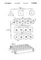
- FIG. 4is a top plan view of a series of blank elements having different geometric shapes suitable for use as masters in accordance with the method of the invention.
- FIG. 5is a top plan view of the ruled masters formed of the blanks of FIG. 4, indicating how each of the respective types of ruled masters can be organized into a cluster with like masters to provide contiguous and continuous surfaces without gaps therebetween.
- FIG. 6is a perspective representation of the manner in which triangular masters of the type shown in FIG. 5 can be organized to permit the production of electroform copies of a ruled master.
- FIG. 7is a schematic representation of the technique employed to create semi-cylindrical segments according to the present invention.
- FIGS. 8 to 11show the progressive positions and size of a shield used during the electroforming creation of the semi-cylindrical segment copies.
- FIG. 12is a representational plan view of a tank and shield demonstrating expansion of the shield's position during electroforming of the cylindrical tool master;
- FIG. 13is a schematic representation of the arrangement of the semi-cylindrical segment copies into a complete cylinder.
- FIG. 14is a schematic representation of the cylinder produced by the semi-cylindrical segment copies.
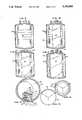
- FIG. 15is a front perspective view of a suction tool used to remove a completed cylindrical embossing tool from its mother.
- FIG. 16is a side view of the tool of FIG. 15 with the cylindrical embossing tool removed to better display the construction of such tool;
- FIG. 17is a diagrammatic representation of a collapsed cylindrical tool prior to removal from its mother.
- FIGS. 1 to 5there are shown various aspects of a blank element which is the basic building element for producing large scale, flexible, seamless cylindrical embossing tools according to the process of the present invention.
- the overall length and width of the element which becomes the ruled masterusually is determined by the type of ruling device used to cut the master, and the element may be on the order of one to seven inches on a side.
- the outline shape of the element, as is shown in FIG. 4may be triangular, as at 20, square as at 23, or hexagonal as at 25.
- FIG. 5illustrates how a number of triangular ruled masters 21 can be arranged into a cluster 22. Similarly a number of square ruled masters 27 and hexagonal masters 29 can be positioned to form clusters 24 and 26 respectively.
- Each element such as 20is chosen of a thickness such that it remains rigid during the removal of metal while undergoing generation of the ruled master and during subsequent electro-forming processes.
- the elementpreferably is of aluminum or electro-deposited copper.
- Ruling machines used in forming scribing grooves to provide a ruled master to make a tool for cube-corner sheetingare well known in the art. Such machines are capable of positioning the workpiece and a cutter within the optical tolerances necessary to scribe the grooves to optical requirements including proper depth, angle, spacing and a mirror finish. Typical groove spacings to form cube-corner type reflector elements range from 0.003 to 0.0065 inches.
- the ruling devicemust be such that a groove uniform in angle and depth is created along its entire length, and that each successive groove also is properly spaced and uniform.
- the ruling devicecan be of the type where the cutter is moved while the workpiece remains stationary or, conversely, the workpiece is moved with respect to a stationary, usually a diamond tipped cutter. Further, the ruling device must be capable of accurately indexing to the second and third or more cutting positions different from the initial set of grooves.
- the element 20 for the ruled master 21 of FIG. 3is positioned upon a workpiece support of an appropriate ruling device (schematically at "A" in FIG. 1) and the cutter thereof set to cut a first series of parallel grooves 31, arbitrarily selected, along the axis in the direction of the arrow 32.
- the cutterhas a V-shaped cutting edge of desired pitch and depth.
- the first set of grooves 31is filled along the axis 32 with a material of appropriate hardness and machinability to allow a second set of grooves 34 to be cut without interruption, as if the first set of grooves 31 did not exist.
- Thisallows the material being removed during cutting to be pushed directly ahead of the cutter instead of into the first set of grooves at each groove intersection, and thereby possibly distorting the intersections.
- the fillalso serves to support the faces of the tetrahedral elements being created and prevents their distortion. Epoxy or curable polyesters can be used as the fill materials.
- a second set of grooves 34is then cut along the axis in the direction of the arrow 35.
- the remaining fill materiali.e., that portion not at the intersections of the second grooves 34 with the first grooves 31
- Fill materialthen is applied to both sets of grooves and 34 prior to the cutting of a third set of grooves.
- the element 20(or tool) is then indexed to proper position to cut a third set of grooves.
- all of the fill materialis removed and the ruled master 21 is ready for the next step.
- One suitable materialis a casting polyester known as Decra-Coat manufactured by Resco.
- a suitable epoxyis Hardman No. 8173.
- FIGS. 1A and 2show a complete ruled master 27 having a square configuration.
- a first set of grooves 31was cut along the axes 32, followed by a second set 34 along the axes 35 and a third set of grooves 37 along the axes 38.
- the intersections of the three groovescreates a base 41 for each of the tetrahedrons or cube-corner elements 40, while the pitch of the cutting tool determines the slope of the three mutually perpendicular faces 42, 43 and 44 of the cube corner elements 40.
- the intersection of the planes of the faces 42, 43 and 44is the apex 45 of the tetrahedron 40.
- the ruling devices presently available to cut masters to the optical accuracy required for cube-corner retroreflectorsare not capable of cutting a single master large enough to be used directly to emboss a web of the desired width and of a length large enough to permit efficient operation. Accordingly, the master such as 21 or 27 must be used to produce copies which can be grouped together to form larger areas until a tool of the desired dimensions is created. Two options are possible at this stage.
- a number of ruled masters 21(which may or may not be identical) are produced and then are arranged in a cluster such as 22, 24 or 26, and assembled in a fixture as at 49 (See FIG. 6), and a thick nickel electroform solid copy is made by techniques known to those in the electroforming arts.
- the deposited nickelcan be controlled to produce a solid copy without interfaces and of uniform thickness throughout.
- This solid copythen can be used to generate additional copies needed for the next step, and the clusters 22 can be disassembled and used for other configurations.
- the first solid copythen will be a female having been formed from a number of the male masters 21.
- a second approachemploys a single master 21 which is used to generate a mother copy 19 (FIG. 1) which then is replicated to generate a number of electro-deposited nickel copies 28 (shown at C on FIG. 1) and the copies 28 of the master 21 then are arranged in a cluster 22 and assembled into a fixture 49.
- a solid copythen is made from the clustered copies of the ruled master 21 (steps D, E, F in FIG. 1). Two successive electroform steps are performed so that strip 50 of male cube corner elements corresponding exactly to the ruled master 21 is produced.
- the solid copies 28are used to generate the thin electroform copy or strip 50.
- the thin strip 50is then employed to form a plurality of strips 51 of female cube-corner elements as shown at H, I and J of FIG. 1.
- the strips 51are then ground on their rear surfaces to a specific thickness to provide the desired flexibility whereby the strips 51 can be formed about an appropriate mandrel 53 (FIG. 1, step K) for succeeding steps.
- an appropriate mandrel 53FIG. 1, step K
- four strips 51each approximately 5 inches in width and 18 inches long, may be produced from the solid copies 28 and arranged about a cylindrical mandrel 53 so as to provide a cylindrical segment copy 55 (FIG. 1 step M) which is 20 inches wide and 18 inches long.
- Three cylindrical segment copies 55then are employed to produce a final embossing tool which is 20 inches wide and approximately 54 inches in circumference. Larger strips and more numerous strips 51 will be used to produce larger tools.
- FIGS. 7 to 11show the method by which the segment copies 55 are generated.
- Each cylindrical segment copy 55is about 1/3 of the circumference of the final mother tool for generating the embossing tool.
- different sized segmentscould be made for specific applications, such as 1/4 segments or the like.
- the segment copy 55could be made thin and bent into its desired shape by an outer support or it could be produced as a relatively thick member formed in its desired shape in order to retain the optical accuracy and provide strength for later operations.
- the female strips 51are placed about mandrel 53 and both mandrel 53 and strips 51 are placed in the electrodeposition tank 57 (see step L of FIG. 1) adjacent the nickel anodes 61.
- FIGS. 8 to 11show the successive positions of the shield 60 during plating. In FIGS.
- the mandrel 53is rotated on a vertical axis for representational purposes.
- the strips 51are positioned on the mandrel 51 initially and no shield is employed as shown in FIG. 8.
- the anodes 61have been omitted from FIGS. 8-11 for the sale of clarity.
- the anodes 61normally would be aligned with the strips 51 and exist above the plane of the paper. With such an arrangement, the greatest nickel build up would be about the central portion of the strips 51.
- the shield 60is placed over the central portion of the strips 51, as is shown in FIG. 9.
- the shield 60is supported by two support rods 62 and 63, which also define the extent of the shield 60. Since the nickel ions do not pass through the shield 60, they travel towards the ends of the strips 51 which are furthest away from the electrodes, to build up the thickness of the electro-deposition in such areas.
- FIGS. 10 and 11show the further extent of the shield 60.
- a diagrammatic representation of the shield 60 on successive time periods 2, 3 and 4is illustrated in plan view in FIG. 12. During period 1, the strip 51 is fully exposed (no shield).
- segment copies 55(FIG. 1) with their precision patterns on the inside, and each comprising 1/3 of the circumference of a final cylinder, are placed within fixtures (not shown) for support to define a segment cylinder 65 (FIG. 14).
- the segment cylinder 65will be plated on its inside diameter to generate a thin flexible but solid seamless master cylinder 70 having flash or fins which can be ground off so no stress risers are transferred to the next part.
- This cylinderthen could be used as a model to produce similar cylinders without repeating all of the previous steps (steps A-N in FIG. 1).
- the segmentdisassembled into the segment copies 55, leaving the tool master cylinder 70.
- the master cylinder 70now consists of female cubes which are situated on the outside diameter.
- This cylinder 70is identical in configuration to that which is required as an embossing tool, however, tools produced by this method (using several segments 55 joined together as a mandrel) have a number of disadvantages. They require an intricate assembly and disassembly of the segment fixture which requires precision alignment. Also of concern is the interface between the thin segments 55 which contain extremely small fissures. Although this discontinuity is almost non-detectable, it causes a difference in the crystalline structure of the metal deposited over it. This change results in stress-risers which become lineal imperfections causing early fatigue failures in parts that will be flexed during embossing.
- the tool master cylinder 70will have surface imperfections such as flash, due to the fissures in the mother fixture, removed by grinding. Once this flash is removed, subsequent copies made from such part will not contain stress risers or alterations in the metallurgical structure, although this cylinder 70, when used as a mandrel does have these imperfections.
- the tool master cylinder 70With proper fixturing (not shown), the tool master cylinder 70 then is rotated during subsequent electroforming, with nickel anodes adjacent its outer surface to form a thick electroform mother cylinder 75, on the order of 0.050" to 0.100", as compared to the tool master cylinder 70 which is of a thickness of only 0.010" to 0.030".
- the thick mother cylinder 75then becomes the negative of a cylindrical embossing tool 80.
- Both mother cylinder 75 and the cylindrical embossing tool 80 formed on the inner surface thereofare continuous and seamless.
- the present inventionutilizes a novel method to separate the seamless embossing tool 80 from the mother cylinder 75, without damage to either.
- Normal "sweating" techniquesexpanding one cylinder and contracting the other by temperature differential
- the vacuum apparatus 90consists of a tube 91 to which is affixed several hollow suction cups 92.
- Independently controlled hoses 93 and 94are affixed one to each cup 92 (see FIG. 16) to create a vacuum.
- Each cup 92is secured to the tube 91 by threaded rods 95 and nuts 96.
- the ends of the inner tool cylinder 80can be held up mechanically or manually and the vacuum apparatus 90 removed.
- the thickness of the tool 80(about 0.010" to 0.030") permits it to flex without damage to the cube corner elements.
- the inner cylinder 80then is totally collapsed, (FIG. 17), either manually or by mechanical means.
- a thin protective filmsuch as Mylar is positioned between the two cylinders 75 and 80 to insure removal without digging either surface.
- the inner tool cylinder 80then is pulled clear from the outer cylinder 75 and recovers its shape.
- the heavy mother cylinder 75can continue to be used to produce similar embossing tools 80 at a rate of 12 to 48 hours per copy, depending on the plating rate used.
- the process disclosed hereincan be varied along the various steps if a smaller embossing tool is required or extended if a larger tool is desired.
- the tool 80is described as a cylinder during its production, because of its ability to flex, it may be employed in other forms. For example, it may be used as a belt having two long sides with short curved ends where it passes over drive rollers (step T of FIG. 1).
Landscapes
- Engineering & Computer Science (AREA)
- Mechanical Engineering (AREA)
- Life Sciences & Earth Sciences (AREA)
- Forests & Forestry (AREA)
- Manufacturing & Machinery (AREA)
- Shaping Of Tube Ends By Bending Or Straightening (AREA)
Abstract
Description
Claims (11)
Priority Applications (1)
| Application Number | Priority Date | Filing Date | Title |
|---|---|---|---|
| US06/903,226US5156863A (en) | 1982-09-30 | 1986-09-02 | Continuous embossing belt |
Applications Claiming Priority (2)
| Application Number | Priority Date | Filing Date | Title |
|---|---|---|---|
| US06/430,866US4478769A (en) | 1982-09-30 | 1982-09-30 | Method for forming an embossing tool with an optically precise pattern |
| US06/903,226US5156863A (en) | 1982-09-30 | 1986-09-02 | Continuous embossing belt |
Related Parent Applications (1)
| Application Number | Title | Priority Date | Filing Date |
|---|---|---|---|
| US06627285Continuation | 1984-07-02 |
Publications (1)
| Publication Number | Publication Date |
|---|---|
| US5156863Atrue US5156863A (en) | 1992-10-20 |
Family
ID=27028813
Family Applications (1)
| Application Number | Title | Priority Date | Filing Date |
|---|---|---|---|
| US06/903,226Expired - Fee RelatedUS5156863A (en) | 1982-09-30 | 1986-09-02 | Continuous embossing belt |
Country Status (1)
| Country | Link |
|---|---|
| US (1) | US5156863A (en) |
Cited By (72)
| Publication number | Priority date | Publication date | Assignee | Title |
|---|---|---|---|---|
| US5543028A (en)* | 1994-11-23 | 1996-08-06 | Xerox Corporation | Electroforming semi-step carousel, and process for using the same |
| US5670188A (en)* | 1994-12-19 | 1997-09-23 | Eastman Kodak Company | Apparatus for single-sided, cold mechanical knurling |
| US5734501A (en)* | 1996-11-01 | 1998-03-31 | Minnesota Mining And Manufacturing Company | Highly canted retroreflective cube corner article |
| US5759468A (en)* | 1993-10-20 | 1998-06-02 | Minnesota Mining And Manufacturing Company | Raised zone retroreflective cube corner article and method of manufacture |
| US5764413A (en)* | 1995-06-09 | 1998-06-09 | Minnesota Mining And Manufacturing Company | Tiled retroreflective sheeting |
| US5831767A (en)* | 1993-10-20 | 1998-11-03 | Minnesota Mining And Manufacturing Company | Asymmetric cube corner article |
| WO1999001273A1 (en)* | 1997-07-02 | 1999-01-14 | Minnesota Mining And Manufacturing Company | Retroreflective cube corner sheeting, molds therefore, and methods of making the same |
| WO1999001275A1 (en)* | 1997-07-02 | 1999-01-14 | Minnesota Mining And Manufacturing Company | Cube corner sheeting mold and method of making the same |
| US5946991A (en)* | 1997-09-03 | 1999-09-07 | 3M Innovative Properties Company | Method for knurling a workpiece |
| US5975987A (en)* | 1995-10-05 | 1999-11-02 | 3M Innovative Properties Company | Method and apparatus for knurling a workpiece, method of molding an article with such workpiece, and such molded article |
| US5981032A (en)* | 1997-07-02 | 1999-11-09 | 3M Innovative Properties Company | Retroreflective cube corner sheeting mold and sheeting formed therefrom |
| US6021559A (en)* | 1996-11-01 | 2000-02-08 | 3M Innovative Properties Company | Methods of making a cube corner article master mold |
| US6253442B1 (en) | 1997-07-02 | 2001-07-03 | 3M Innovative Properties Company | Retroreflective cube corner sheeting mold and method for making the same |
| US6287670B1 (en) | 1999-01-11 | 2001-09-11 | 3M Innovative Properties Company | Cube corner cavity based retroreflectors and methods for making same |
| KR20010107275A (en)* | 2000-05-26 | 2001-12-07 | 김현대 | Method of manufacturing valve of reflective sheet successive molder |
| US20020196401A1 (en)* | 2001-06-25 | 2002-12-26 | Grace Anthony J. | Hybrid display device |
| US6514594B1 (en) | 2000-11-09 | 2003-02-04 | Avery Dennison Corporation | Fluorescent polymeric articles having screening layer formed from U.V. light absorbing polymer |
| US6540367B1 (en) | 1999-04-07 | 2003-04-01 | 3M Innovative Properties Company | Structured surface articles containing geometric structures with compound faces and methods for making same |
| US6641767B2 (en)* | 2000-03-10 | 2003-11-04 | 3M Innovative Properties Company | Methods for replication, replicated articles, and replication tools |
| US20030206256A1 (en)* | 2002-05-06 | 2003-11-06 | Drain Kieran F. | Display device with backlight |
| US20030213129A1 (en)* | 2000-07-28 | 2003-11-20 | Warner-Lambert Company Llc | Microprismatic shaving surface and shaving implements incorporating said surface |
| US20030227683A1 (en)* | 2002-06-11 | 2003-12-11 | 3M Innovative Properties Company | Retroreflective articles having moire-like pattern |
| US20030232156A1 (en)* | 2002-06-14 | 2003-12-18 | Kimberly-Clark Worldwide,Inc. | Multilens star box and method for making same |
| WO2003104858A1 (en)* | 2002-06-11 | 2003-12-18 | 3M Innovative Properties Company | Methods of making a master and replicas thereof |
| US6727970B2 (en) | 2001-06-25 | 2004-04-27 | Avery Dennison Corporation | Method of making a hybrid display device having a rigid substrate and a flexible substrate |
| US6752947B1 (en) | 1998-07-16 | 2004-06-22 | Hercules Incorporated | Method and apparatus for thermal bonding high elongation nonwoven fabric |
| US20040166258A1 (en)* | 2003-02-25 | 2004-08-26 | Kimberly-Clark Worldwide, Inc. | Decorative film, carton, and method of making |
| US20040174603A1 (en)* | 2003-03-06 | 2004-09-09 | 3M Innovative Properties Company | Lamina comprising cube corner elements and retroreflective sheeting |
| US20040175541A1 (en)* | 2003-03-06 | 2004-09-09 | 3M Innovative Properties Company | Methods of making microstructured lamina and apparatus |
| US20040174602A1 (en)* | 2003-03-06 | 2004-09-09 | 3M Innovative Properties Company | Method of making retroreflective sheeting and articles |
| US20040173920A1 (en)* | 2003-03-06 | 2004-09-09 | 3M Innovative Properties Company | Method of making retroreflective sheeting and slot die apparatus |
| US20040190144A1 (en)* | 2003-03-12 | 2004-09-30 | Hannington Michael E. | Rear projection screens and methods of making the same |
| US6843571B2 (en) | 2002-06-11 | 2005-01-18 | 3M Innovative Properties Company | Methods of making a master and replicas thereof |
| US20050147796A1 (en)* | 2000-02-25 | 2005-07-07 | 3M Innovative Properties Company | Compound mold and structured surface articles containing geometric structures with compound faces and method of making same |
| US20050226590A1 (en)* | 2004-04-07 | 2005-10-13 | Patel Falgun D | Variable optical attenuator based on rare earth doped glass |
| US20050239935A1 (en)* | 2004-04-26 | 2005-10-27 | Kang Gary Y | Roll-to-roll embossing tools and processes |
| US6972147B1 (en) | 2000-11-09 | 2005-12-06 | Avery Dennison Corporation | Fluorescent polymeric articles fabricated from U.V. light absorbing polymer |
| US20060007542A1 (en)* | 2003-03-06 | 2006-01-12 | 3M Innovative Properties Company | Retroreflective sheeting having high retroreflectance at low observation angles |
| US7007393B2 (en) | 2002-07-16 | 2006-03-07 | Eveready Battery Company, Inc. | Microreplicated shaving element |
| US20060210769A1 (en)* | 2000-11-21 | 2006-09-21 | Susan Swindlehurst | Method of making a flexible substrate containing self-assembling microstructures |
| US20060266477A1 (en)* | 2005-05-24 | 2006-11-30 | General Electric Company | Method and apparatus for reducing surface defects |
| US20070037960A1 (en)* | 2005-08-15 | 2007-02-15 | General Electric Company | Copolyester stilbene embossed film and methods of making the same |
| US20070042129A1 (en)* | 2005-08-22 | 2007-02-22 | Kang Gary Y | Embossing assembly and methods of preparation |
| US20070240585A1 (en)* | 2006-04-13 | 2007-10-18 | Nitin Vaish | Embossing system, methods of use, and articles produced therefrom |
| WO2007121284A2 (en) | 2006-04-18 | 2007-10-25 | 3M Innovative Properties Company | Microstructured articles comprising nitrogen containing ingredient |
| US20070281137A1 (en)* | 2006-06-01 | 2007-12-06 | Kuolih Tsai | Heat-transfer label assembly and apparatus for applying heat-transfer labels |
| US20080012162A1 (en)* | 2006-07-17 | 2008-01-17 | Chapman Steven R | Method of making an array of aberrated optical elements |
| US20080233404A1 (en)* | 2007-03-22 | 2008-09-25 | 3M Innovative Properties Company | Microreplication tools and patterns using laser induced thermal embossing |
| US20100103521A1 (en)* | 2008-10-22 | 2010-04-29 | 3M Innovative Properties Company | Retroreflective sheeting |
| USRE41694E1 (en) | 2002-06-14 | 2010-09-14 | Xiao-Ming He | Method for roll-to-roll deposition of optically transparent and high conductivity metallic thin films |
| EP2233953A2 (en) | 1999-04-07 | 2010-09-29 | 3M Innovative Properties Co. | Mold with structured surface and retroreflective article made using the mold |
| US20110266709A1 (en)* | 2010-04-30 | 2011-11-03 | Song Tae-Joon | Apparatus and method of fabricating flat panel display device |
| US8534849B2 (en) | 2009-04-15 | 2013-09-17 | 3M Innovative Properties Company | Retroreflecting optical construction |
| EP2641730A2 (en) | 2012-03-23 | 2013-09-25 | ORAFOL Americas Inc. | Methods for fabricating a retroreflector tooling and retroreflective microstructures and devices thereof |
| WO2014116431A1 (en) | 2013-01-28 | 2014-07-31 | 3M Innovative Properties Company | Retroreflective sheeting having deformed cube corner elements |
| US8891038B2 (en) | 2009-04-15 | 2014-11-18 | 3M Innovative Properties Company | Lightguide with optical film containing voids and blacklight for display system |
| US8950877B2 (en) | 2009-11-12 | 2015-02-10 | 3M Innovative Properties Company | Security markings in retroreflective sheeting |
| US8964146B2 (en) | 2009-04-15 | 2015-02-24 | 3M Innovative Properties Company | Optical film for preventing optical coupling |
| US9291752B2 (en) | 2013-08-19 | 2016-03-22 | 3M Innovative Properties Company | Retroreflecting optical construction |
| WO2016168534A1 (en) | 2015-04-15 | 2016-10-20 | Avery Dennison Corporation | Vented tooling belt for production of structured surfaces |
| WO2017004247A1 (en) | 2015-06-30 | 2017-01-05 | 3M Innovative Properties Company | A barrier element on a microstructured article |
| WO2017007615A1 (en) | 2015-07-07 | 2017-01-12 | 3M Innovative Properties Company | Polyurethane layer for a light directing article |
| US9618663B2 (en) | 2010-04-15 | 2017-04-11 | 3M Innovative Properties Company | Retroreflective articles including optically active areas and optically inactive areas |
| US9703023B2 (en) | 2013-03-15 | 2017-07-11 | 3M Innovative Properties Company | Microtiled prismatic cube corner articles |
| US9791604B2 (en) | 2010-04-15 | 2017-10-17 | 3M Innovative Properties Company | Retroreflective articles including optically active areas and optically inactive areas |
| WO2017214007A1 (en) | 2016-06-07 | 2017-12-14 | 3M Innovative Properties Company | Acrylic polyvinyl acetal film for a light directing article |
| US9884447B2 (en) | 2012-04-06 | 2018-02-06 | 3M Innovative Properties Company | Tools for making retroreflective articles |
| US9910194B2 (en) | 2010-04-15 | 2018-03-06 | 3M Innovative Properties Company | Retroreflective articles including optically active areas and optically inactive areas |
| WO2018151959A1 (en) | 2017-02-14 | 2018-08-23 | 3M Innovative Properties Company | End milling methods for making microstructures, especially cube corner elements and articles comprising such microstructures |
| US10082609B2 (en) | 2009-11-12 | 2018-09-25 | 3M Innovative Properties Company | Irradiation marking of retroreflective sheeting |
| US10649274B2 (en) | 2009-04-15 | 2020-05-12 | 3M Innovative Properties Company | Optical construction and display system incorporating same |
| WO2022046134A1 (en) | 2020-08-27 | 2022-03-03 | Aura Optical System, LP | Microprismatic retroreflective mold, sheet, and article and methods of manufacture thereof |
Citations (19)
| Publication number | Priority date | Publication date | Assignee | Title |
|---|---|---|---|---|
| US1445626A (en)* | 1920-02-21 | 1923-02-20 | Mechanical Rubber Co | Method of making tires for carpet sweepers |
| US1555840A (en)* | 1923-06-18 | 1925-10-06 | John A Hanley | Flexible band or belt and the production thereof |
| US1668390A (en)* | 1926-05-17 | 1928-05-01 | John W Auman | Method of and apparatus for forming tire and the like tubes |
| US2551005A (en)* | 1946-12-04 | 1951-05-01 | Goodrich Co B F | Surface finishing thermoplastic materials |
| US2567275A (en)* | 1944-02-16 | 1951-09-11 | Colombo Roberto | Apparatus and method of goffering thermoplastic materials |
| US2569367A (en)* | 1946-01-08 | 1951-09-25 | Champion Paper & Fibre Co | Endless metal belt and method of making the same |
| US3170974A (en)* | 1962-06-06 | 1965-02-23 | Sun Chemical Corp | Process for embossing foamed thermoplastic sheets |
| US3387351A (en)* | 1965-05-28 | 1968-06-11 | Kleinewefers Gravuren G M B H | Method of making stamping and embossing rollers |
| US3476657A (en)* | 1967-03-28 | 1969-11-04 | Friden Inc | Method of forming a font belt |
| US3704175A (en)* | 1971-02-01 | 1972-11-28 | Budd Co | Electroforming jointless metal belt |
| US3758649A (en)* | 1971-06-21 | 1973-09-11 | Rca Corp | Method of manufacturing holographic replicas |
| US3799859A (en)* | 1972-05-08 | 1974-03-26 | Xerox Corp | Electroforming system |
| US3882202A (en)* | 1971-12-27 | 1975-05-06 | Bayer Ag | Amidothionophosphoric acid esters |
| US3935359A (en)* | 1972-06-23 | 1976-01-27 | Rowland Development Corporation | Retroreflective sheeting and method and apparatus for producing same |
| US4280978A (en)* | 1979-05-23 | 1981-07-28 | Monsanto Company | Process of embossing and perforating thermoplastic film |
| US4318794A (en)* | 1980-11-17 | 1982-03-09 | Edward Adler | Anode for production of electrodeposited foil |
| US4326928A (en)* | 1981-01-26 | 1982-04-27 | General Dynamics, Pomona Division | Method of electroforming |
| US4396465A (en)* | 1980-06-24 | 1983-08-02 | Newell Research Corporation | Method for making seamless metallic ribbon belts for tape cartridges |
| US4486363A (en)* | 1982-09-30 | 1984-12-04 | Amerace Corporation | Method and apparatus for embossing a precision optical pattern in a resinous sheet |
- 1986
- 1986-09-02USUS06/903,226patent/US5156863A/ennot_activeExpired - Fee Related
Patent Citations (19)
| Publication number | Priority date | Publication date | Assignee | Title |
|---|---|---|---|---|
| US1445626A (en)* | 1920-02-21 | 1923-02-20 | Mechanical Rubber Co | Method of making tires for carpet sweepers |
| US1555840A (en)* | 1923-06-18 | 1925-10-06 | John A Hanley | Flexible band or belt and the production thereof |
| US1668390A (en)* | 1926-05-17 | 1928-05-01 | John W Auman | Method of and apparatus for forming tire and the like tubes |
| US2567275A (en)* | 1944-02-16 | 1951-09-11 | Colombo Roberto | Apparatus and method of goffering thermoplastic materials |
| US2569367A (en)* | 1946-01-08 | 1951-09-25 | Champion Paper & Fibre Co | Endless metal belt and method of making the same |
| US2551005A (en)* | 1946-12-04 | 1951-05-01 | Goodrich Co B F | Surface finishing thermoplastic materials |
| US3170974A (en)* | 1962-06-06 | 1965-02-23 | Sun Chemical Corp | Process for embossing foamed thermoplastic sheets |
| US3387351A (en)* | 1965-05-28 | 1968-06-11 | Kleinewefers Gravuren G M B H | Method of making stamping and embossing rollers |
| US3476657A (en)* | 1967-03-28 | 1969-11-04 | Friden Inc | Method of forming a font belt |
| US3704175A (en)* | 1971-02-01 | 1972-11-28 | Budd Co | Electroforming jointless metal belt |
| US3758649A (en)* | 1971-06-21 | 1973-09-11 | Rca Corp | Method of manufacturing holographic replicas |
| US3882202A (en)* | 1971-12-27 | 1975-05-06 | Bayer Ag | Amidothionophosphoric acid esters |
| US3799859A (en)* | 1972-05-08 | 1974-03-26 | Xerox Corp | Electroforming system |
| US3935359A (en)* | 1972-06-23 | 1976-01-27 | Rowland Development Corporation | Retroreflective sheeting and method and apparatus for producing same |
| US4280978A (en)* | 1979-05-23 | 1981-07-28 | Monsanto Company | Process of embossing and perforating thermoplastic film |
| US4396465A (en)* | 1980-06-24 | 1983-08-02 | Newell Research Corporation | Method for making seamless metallic ribbon belts for tape cartridges |
| US4318794A (en)* | 1980-11-17 | 1982-03-09 | Edward Adler | Anode for production of electrodeposited foil |
| US4326928A (en)* | 1981-01-26 | 1982-04-27 | General Dynamics, Pomona Division | Method of electroforming |
| US4486363A (en)* | 1982-09-30 | 1984-12-04 | Amerace Corporation | Method and apparatus for embossing a precision optical pattern in a resinous sheet |
Cited By (223)
| Publication number | Priority date | Publication date | Assignee | Title |
|---|---|---|---|---|
| US6413615B2 (en) | 1993-10-20 | 2002-07-02 | 3M Innovative Properties Company | Cube corner geometric structures in a substrate formed by both replicating and machining processes |
| US6136416A (en)* | 1993-10-20 | 2000-10-24 | 3M Innovative Properties Company | Raised zone retroreflective cube corner article |
| US5759468A (en)* | 1993-10-20 | 1998-06-02 | Minnesota Mining And Manufacturing Company | Raised zone retroreflective cube corner article and method of manufacture |
| US5831767A (en)* | 1993-10-20 | 1998-11-03 | Minnesota Mining And Manufacturing Company | Asymmetric cube corner article |
| US6277470B1 (en) | 1993-10-20 | 2001-08-21 | 3M Innovative Properties Company | Method of forming cube corner geometric structures in a substrate using both replicating and machining processes |
| US5543028A (en)* | 1994-11-23 | 1996-08-06 | Xerox Corporation | Electroforming semi-step carousel, and process for using the same |
| US5670188A (en)* | 1994-12-19 | 1997-09-23 | Eastman Kodak Company | Apparatus for single-sided, cold mechanical knurling |
| US5926314A (en)* | 1995-06-09 | 1999-07-20 | Minnesota Mining And Manufacturing Company | Retroreflective cube corner article having scalene base triangles |
| US5822121A (en)* | 1995-06-09 | 1998-10-13 | Minnesota Mining And Manufacturing Company | Retroreflective cube corner article having scalene base triangles |
| US5812315A (en)* | 1995-06-09 | 1998-09-22 | Minnesota Mining And Manufacturing Company | Cube corner articles exhibiting improved entrance angularity in one or more planes |
| US5764413A (en)* | 1995-06-09 | 1998-06-09 | Minnesota Mining And Manufacturing Company | Tiled retroreflective sheeting |
| US5975987A (en)* | 1995-10-05 | 1999-11-02 | 3M Innovative Properties Company | Method and apparatus for knurling a workpiece, method of molding an article with such workpiece, and such molded article |
| US6021559A (en)* | 1996-11-01 | 2000-02-08 | 3M Innovative Properties Company | Methods of making a cube corner article master mold |
| US5734501A (en)* | 1996-11-01 | 1998-03-31 | Minnesota Mining And Manufacturing Company | Highly canted retroreflective cube corner article |
| US6386855B1 (en) | 1997-07-02 | 2002-05-14 | 3M Innovative Properties Company | Cube corner sheeting mold and of making the same |
| US6318987B1 (en) | 1997-07-02 | 2001-11-20 | 3M Innovative Properties Company | Cube corner sheeting mold and method of making the same |
| US6120881A (en)* | 1997-07-02 | 2000-09-19 | 3M Innovative Properties Company | Retroreflective cube corner sheeting mold and sheeting formed therefrom |
| US5981032A (en)* | 1997-07-02 | 1999-11-09 | 3M Innovative Properties Company | Retroreflective cube corner sheeting mold and sheeting formed therefrom |
| US6114009A (en)* | 1997-07-02 | 2000-09-05 | 3M Innovative Properties Company | Asymmetric retroreflective cube corner sheeting mold and sheeting formed therefrom |
| US6253442B1 (en) | 1997-07-02 | 2001-07-03 | 3M Innovative Properties Company | Retroreflective cube corner sheeting mold and method for making the same |
| US6257860B1 (en) | 1997-07-02 | 2001-07-10 | 3M Innovative Properties Company | Cube corner sheeting mold and method of making the same |
| US6533887B1 (en) | 1997-07-02 | 2003-03-18 | 3M Innovative Properties Company | Retroreflective cube corner sheeting, molds therefore, and methods of making the same |
| WO1999001273A1 (en)* | 1997-07-02 | 1999-01-14 | Minnesota Mining And Manufacturing Company | Retroreflective cube corner sheeting, molds therefore, and methods of making the same |
| US6447878B1 (en) | 1997-07-02 | 2002-09-10 | 3M Innovative Properties Company | Retroreflective cube corner sheeting mold and sheeting formed therefrom |
| US6302992B1 (en) | 1997-07-02 | 2001-10-16 | 3M Innovative Properties Company | Retroreflective cube corner sheeting, molds therefore, and methods of making the same |
| CN1086981C (en)* | 1997-07-02 | 2002-07-03 | 美国3M公司 | Retroreflective cube corner sheeting, molds therefor and method of making same |
| US20040212887A1 (en)* | 1997-07-02 | 2004-10-28 | Benson Gerald M. | Retroreflective cube corner sheeting mold and method for making the same |
| WO1999001275A1 (en)* | 1997-07-02 | 1999-01-14 | Minnesota Mining And Manufacturing Company | Cube corner sheeting mold and method of making the same |
| US6386079B2 (en) | 1997-09-03 | 2002-05-14 | 3M Innovative Properties Company | Method and apparatus for knurling a workpiece, method of molding an article with such workpiece, and such molded article |
| US20010023629A1 (en)* | 1997-09-03 | 2001-09-27 | 3M Innovative Properties Company | Method and apparatus for knurling a workpiece, method of molding an article with such workpiece, and such molded article |
| US6959575B2 (en) | 1997-09-03 | 2005-11-01 | 3M Innovative Properties Company | Kurling tool |
| US5946991A (en)* | 1997-09-03 | 1999-09-07 | 3M Innovative Properties Company | Method for knurling a workpiece |
| US6238611B1 (en) | 1997-09-03 | 2001-05-29 | 3M Innovative Properties Company | Method and apparatus for knurling a workpiece, method of molding an article with such workpiece and such molded article |
| US6752947B1 (en) | 1998-07-16 | 2004-06-22 | Hercules Incorporated | Method and apparatus for thermal bonding high elongation nonwoven fabric |
| US6656571B2 (en) | 1999-01-11 | 2003-12-02 | 3M Innovative Properties Company | Cube corner cavity based retroreflectors and methods for making same |
| US6287670B1 (en) | 1999-01-11 | 2001-09-11 | 3M Innovative Properties Company | Cube corner cavity based retroreflectors and methods for making same |
| US6540367B1 (en) | 1999-04-07 | 2003-04-01 | 3M Innovative Properties Company | Structured surface articles containing geometric structures with compound faces and methods for making same |
| EP2244109A2 (en) | 1999-04-07 | 2010-10-27 | 3M Innovative Properties Company | Mold with structured surface and retroreflective article made using the mold |
| US20070177268A1 (en)* | 1999-04-07 | 2007-08-02 | 3M Innovative Properties Company | Structured surface articles containing geometric structures with compound faces and methods for making same |
| EP2264489A2 (en) | 1999-04-07 | 2010-12-22 | 3M Innovative Properties Company | Mold with structured surface and retroreflective article made using the mold |
| US7562991B2 (en) | 1999-04-07 | 2009-07-21 | 3M Innovative Properties Company | Structured surface articles containing geometric structures with compound faces and methods for making same |
| US7712904B2 (en) | 1999-04-07 | 2010-05-11 | 3M Innovative Properties Company | Structured surface articles containing geometric structures with compound faces and methods for making same |
| US20080074743A1 (en)* | 1999-04-07 | 2008-03-27 | 3M Innovative Properties Company | Structured surface articles containing geometric structures with compound faces and methods for making same |
| US20100182695A1 (en)* | 1999-04-07 | 2010-07-22 | 3M Innovative Properties Company | Structured surface articles containing geometric structures with compound faces and methods for making same |
| US7261425B2 (en) | 1999-04-07 | 2007-08-28 | 3M Innovative Properties Company | Structured surface articles containing geometric structures with compound faces and methods for making same |
| EP2233953A2 (en) | 1999-04-07 | 2010-09-29 | 3M Innovative Properties Co. | Mold with structured surface and retroreflective article made using the mold |
| EP2264490A2 (en) | 1999-04-07 | 2010-12-22 | 3M Innovative Properties Company | Mold with structured surface and retroreflective article made using the mold |
| US7384161B2 (en) | 1999-04-07 | 2008-06-10 | 3M Innovative Properties Company | Structured surface articles containing geometric structures with compound faces and methods for making same |
| EP2796906A2 (en) | 1999-04-07 | 2014-10-29 | 3M Innovative Properties Company | Structured surface articles containing geometric structures with compound faces and methods for making same |
| EP2244110A2 (en) | 1999-04-07 | 2010-10-27 | 3M Innovative Properties Company | Mold with structured surface and retroreflective article made using the mold |
| US8485672B2 (en) | 1999-04-07 | 2013-07-16 | 3M Innovative Properties Company | Structured surface articles containing geometric structures with compound faces and methods for making same |
| US8728610B2 (en) | 2000-02-25 | 2014-05-20 | 3M Innovative Properties Company | Compound mold and structured surface articles containing geometric structures with compound faces and method of making same |
| US8394485B2 (en) | 2000-02-25 | 2013-03-12 | 3M Innovative Properties Company | Compound mold and structured surface articles containing geometric structures with compound faces and method of making same |
| US20110149395A1 (en)* | 2000-02-25 | 2011-06-23 | 3M Innovative Properties Company | Compound mold and structured surface articles containing geometric structures with compound faces and method of making same |
| US8852722B2 (en) | 2000-02-25 | 2014-10-07 | 3M Innovative Properties Company | Compound mold and structured surface articles containing geometric structures with compound faces and method of making same |
| US20050147796A1 (en)* | 2000-02-25 | 2005-07-07 | 3M Innovative Properties Company | Compound mold and structured surface articles containing geometric structures with compound faces and method of making same |
| US6641767B2 (en)* | 2000-03-10 | 2003-11-04 | 3M Innovative Properties Company | Methods for replication, replicated articles, and replication tools |
| KR20010107275A (en)* | 2000-05-26 | 2001-12-07 | 김현대 | Method of manufacturing valve of reflective sheet successive molder |
| US20030213129A1 (en)* | 2000-07-28 | 2003-11-20 | Warner-Lambert Company Llc | Microprismatic shaving surface and shaving implements incorporating said surface |
| US6514594B1 (en) | 2000-11-09 | 2003-02-04 | Avery Dennison Corporation | Fluorescent polymeric articles having screening layer formed from U.V. light absorbing polymer |
| US6972147B1 (en) | 2000-11-09 | 2005-12-06 | Avery Dennison Corporation | Fluorescent polymeric articles fabricated from U.V. light absorbing polymer |
| US20060210769A1 (en)* | 2000-11-21 | 2006-09-21 | Susan Swindlehurst | Method of making a flexible substrate containing self-assembling microstructures |
| US6856086B2 (en) | 2001-06-25 | 2005-02-15 | Avery Dennison Corporation | Hybrid display device |
| US20020196401A1 (en)* | 2001-06-25 | 2002-12-26 | Grace Anthony J. | Hybrid display device |
| US6727970B2 (en) | 2001-06-25 | 2004-04-27 | Avery Dennison Corporation | Method of making a hybrid display device having a rigid substrate and a flexible substrate |
| US20030206256A1 (en)* | 2002-05-06 | 2003-11-06 | Drain Kieran F. | Display device with backlight |
| US6843571B2 (en) | 2002-06-11 | 2005-01-18 | 3M Innovative Properties Company | Methods of making a master and replicas thereof |
| US6935756B2 (en) | 2002-06-11 | 2005-08-30 | 3M Innovative Properties Company | Retroreflective articles having moire-like pattern |
| US20030227683A1 (en)* | 2002-06-11 | 2003-12-11 | 3M Innovative Properties Company | Retroreflective articles having moire-like pattern |
| WO2003104859A1 (en)* | 2002-06-11 | 2003-12-18 | 3M Innovative Properties Company | Retroreflective articles having moiré-like pattern |
| WO2003104858A1 (en)* | 2002-06-11 | 2003-12-18 | 3M Innovative Properties Company | Methods of making a master and replicas thereof |
| US20030232156A1 (en)* | 2002-06-14 | 2003-12-18 | Kimberly-Clark Worldwide,Inc. | Multilens star box and method for making same |
| USRE41694E1 (en) | 2002-06-14 | 2010-09-14 | Xiao-Ming He | Method for roll-to-roll deposition of optically transparent and high conductivity metallic thin films |
| WO2003107042A3 (en)* | 2002-06-14 | 2004-03-25 | Kimberly Clark Co | Box having a multilens star decoration and method for making same |
| US6800357B2 (en) | 2002-06-14 | 2004-10-05 | Kimberly-Clark Worldwide, Inc. | Multilens star box and method for making same |
| US7007393B2 (en) | 2002-07-16 | 2006-03-07 | Eveready Battery Company, Inc. | Microreplicated shaving element |
| US7433105B2 (en) | 2003-02-25 | 2008-10-07 | Kimberly-Clark Worldwide, Inc. | Decorative film, carton, and method of making |
| US20040166258A1 (en)* | 2003-02-25 | 2004-08-26 | Kimberly-Clark Worldwide, Inc. | Decorative film, carton, and method of making |
| US7722197B2 (en) | 2003-03-06 | 2010-05-25 | 3M Innovative Properties Company | Lamina comprising cube corner elements and retroreflective sheeting |
| US8262237B2 (en) | 2003-03-06 | 2012-09-11 | 3M Innovative Properties Company | Retroreflective sheeting including cube corner elements |
| US7188960B2 (en) | 2003-03-06 | 2007-03-13 | 3M Innovative Properties Company | Retroreflective sheeting having high retroreflectance at low observation angles |
| US20070107191A1 (en)* | 2003-03-06 | 2007-05-17 | 3M Innovative Properties Company | Methods of making microstructured lamina and apparatus |
| US10884166B2 (en) | 2003-03-06 | 2021-01-05 | 3M Innovative Properties Company | Retroreflective sheeting including cube corner elements |
| US7261424B2 (en) | 2003-03-06 | 2007-08-28 | 3M Innovative Properties Company | Retroreflective sheeting having high retroreflectance at low observation angles |
| US7174619B2 (en) | 2003-03-06 | 2007-02-13 | 3M Innovative Properties Company | Methods of making microstructured lamina and apparatus |
| US7261426B2 (en) | 2003-03-06 | 2007-08-28 | 3M Innovative Properties Company | Lamina comprising cube corner elements and retroreflective sheeting |
| US10562249B2 (en) | 2003-03-06 | 2020-02-18 | 3M Innovative Properties Company | Cube corner retroreflective sheeting having channels |
| US10495792B2 (en) | 2003-03-06 | 2019-12-03 | 3M Innovative Properties Company | Retroreflective sheeting including cube corner elements |
| US10101509B2 (en) | 2003-03-06 | 2018-10-16 | 3M Innovative Properties Company | Retroreflective sheeting including cube corner elements |
| US7309135B2 (en) | 2003-03-06 | 2007-12-18 | 3M Innovative Properties Company | Method of making retroreflective sheeting and articles |
| US9724882B2 (en) | 2003-03-06 | 2017-08-08 | 3M Innovative Properties Company | Cube corner retroreflective sheeting having channels |
| US7329012B2 (en) | 2003-03-06 | 2008-02-12 | 3M Innovative Properties Company | Lamina comprising cube corner elements and retroreflective sheeting |
| US20080068713A1 (en)* | 2003-03-06 | 2008-03-20 | 3M Innovative Properties Company | Method of making retroreflective sheeting and articles |
| US20070014010A1 (en)* | 2003-03-06 | 2007-01-18 | 3M Innovative Properties Company | Lamina comprising cube corner elements and retroreflective sheeting |
| US9470822B2 (en) | 2003-03-06 | 2016-10-18 | 3M Innovative Properties Company | Retroreflective sheeting including cube corner elements |
| US7364421B2 (en) | 2003-03-06 | 2008-04-29 | 3M Innovative Properties Comapny | Method of making retroreflective sheeting and slot die apparatus |
| US20070014012A1 (en)* | 2003-03-06 | 2007-01-18 | 3M Innovative Properties Company | Lamina comprising cube corner elements and retroreflective sheeting |
| US7401396B2 (en) | 2003-03-06 | 2008-07-22 | 3M Innovative Properties Company | Methods of making microstructured lamina and apparatus |
| US7410604B2 (en) | 2003-03-06 | 2008-08-12 | 3M Innovative Properties Company | Method of making retroreflective sheeting and slot die apparatus |
| US7422334B2 (en) | 2003-03-06 | 2008-09-09 | 3M Innovative Properties Company | Lamina comprising cube corner elements and retroreflective sheeting |
| US9465147B2 (en) | 2003-03-06 | 2016-10-11 | 3M Innovative Properties Company | Cube corner retroreflective sheeting having channels |
| US7156527B2 (en) | 2003-03-06 | 2007-01-02 | 3M Innovative Properties Company | Lamina comprising cube corner elements and retroreflective sheeting |
| US7458694B2 (en) | 2003-03-06 | 2008-12-02 | 3M Innovative Properties Company | Method of making retroreflective sheeting and articles |
| EP3006970A1 (en) | 2003-03-06 | 2016-04-13 | 3M Innovative Properties Company of 3M Center | Method of making retroreflective sheeting and articles |
| US7556386B2 (en) | 2003-03-06 | 2009-07-07 | 3M Innovative Properties Company | Lamina comprising cube corner elements and retroreflective sheeting |
| US7152983B2 (en) | 2003-03-06 | 2006-12-26 | 3M Innovative Properties Company | Lamina comprising cube corner elements and retroreflective sheeting |
| US20090185272A1 (en)* | 2003-03-06 | 2009-07-23 | 3M Innovative Properties Company | Method of making retroreflective sheeting and articles |
| US20090257124A1 (en)* | 2003-03-06 | 2009-10-15 | 3M Innovative Properties Company | Lamina comprising cube corner elements and retroreflective sheeting |
| US9188715B2 (en) | 2003-03-06 | 2015-11-17 | 3M Innovative Properties Company | Retroreflective sheeting including cube corner elements |
| US8998428B2 (en) | 2003-03-06 | 2015-04-07 | 3M Innovative Properties Company | Retroreflective sheeting including cube corner elements |
| US20040174603A1 (en)* | 2003-03-06 | 2004-09-09 | 3M Innovative Properties Company | Lamina comprising cube corner elements and retroreflective sheeting |
| US8851686B2 (en) | 2003-03-06 | 2014-10-07 | 3M Innovative Properties Company | Retroreflective sheeting including cube corner elements |
| US7744228B2 (en) | 2003-03-06 | 2010-06-29 | 3M Innovative Properties Company | Method of making retroreflective sheeting and articles |
| US20060134259A1 (en)* | 2003-03-06 | 2006-06-22 | 3M Innovative Properties Company | Method of making retroreflective sheeting and slot die apparatus |
| US20040175541A1 (en)* | 2003-03-06 | 2004-09-09 | 3M Innovative Properties Company | Methods of making microstructured lamina and apparatus |
| US20100226009A1 (en)* | 2003-03-06 | 2010-09-09 | 3M Innovative Properties Company | Method of making retroreflective sheeting and articles |
| US20060007542A1 (en)* | 2003-03-06 | 2006-01-12 | 3M Innovative Properties Company | Retroreflective sheeting having high retroreflectance at low observation angles |
| US20100232019A1 (en)* | 2003-03-06 | 2010-09-16 | 3M Innovative Properties Company | Lamina comprising cube corner elements and retroreflective sheeting |
| US20040174602A1 (en)* | 2003-03-06 | 2004-09-09 | 3M Innovative Properties Company | Method of making retroreflective sheeting and articles |
| EP2237082A2 (en) | 2003-03-06 | 2010-10-06 | 3M Innovative Properties Co. | Lamina comprising cube corner elements and retroreflective sheeting |
| US8714757B1 (en) | 2003-03-06 | 2014-05-06 | 3M Innovative Properties Company | Retroreflective sheeting including cube corner elements |
| US20050180012A1 (en)* | 2003-03-06 | 2005-08-18 | 3M Innovative Properties Company | Method of making retroreflective sheeting and articles |
| EP2258540A1 (en) | 2003-03-06 | 2010-12-08 | 3M Innovative Properties Company | Retroreflective sheeting |
| EP2261013A2 (en) | 2003-03-06 | 2010-12-15 | 3M Innovative Properties Company | Method of making retroreflective sheeting and articles |
| EP2260971A2 (en) | 2003-03-06 | 2010-12-15 | 3M Innovative Properties Company | Methods of making microstructured lamina and apparatus |
| EP2260970A2 (en) | 2003-03-06 | 2010-12-15 | 3M Innovative Properties Company | Methods of making microstructured lamina and apparatus |
| US6884371B2 (en)* | 2003-03-06 | 2005-04-26 | 3M Innovative Properties Company | Method of making retroreflective sheeting and articles |
| US8708504B2 (en) | 2003-03-06 | 2014-04-29 | 3M Innovative Properties Company | Retroreflective sheeting including cube corner elements |
| US8596800B2 (en) | 2003-03-06 | 2013-12-03 | 3M Innovative Properties Company | Cube corner retroreflective sheeting having channels |
| US8016435B2 (en) | 2003-03-06 | 2011-09-13 | 3M Innovative Properties Company | Lamina comprising cube corner elements and retroreflective sheeting |
| US8573789B2 (en) | 2003-03-06 | 2013-11-05 | 3M Innovative Properties Company | Retroreflective sheeting including cube corner elements |
| US20040173920A1 (en)* | 2003-03-06 | 2004-09-09 | 3M Innovative Properties Company | Method of making retroreflective sheeting and slot die apparatus |
| EP2442150A2 (en) | 2003-03-06 | 2012-04-18 | 3M Innovative Properties Co. | Lamina comprising cube corner elements and retroreflective sheeting |
| EP2442159A2 (en) | 2003-03-06 | 2012-04-18 | 3M Innovative Properties Co. | Lamina comprising cube corner elements and retroreflective sheeting |
| EP2442148A2 (en) | 2003-03-06 | 2012-04-18 | 3M Innovative Properties Co. | Lamina comprising cube corner elements and retroreflective sheeting |
| EP2442157A2 (en) | 2003-03-06 | 2012-04-18 | 3M Innovative Properties Co. | Lamina comprising cube corner elements and retroreflective sheeting |
| EP2442152A2 (en) | 2003-03-06 | 2012-04-18 | 3M Innovative Properties Co. | Lamina comprising cube corner elements and retroreflective sheeting |
| EP2442156A2 (en) | 2003-03-06 | 2012-04-18 | 3M Innovative Properties Co. | Lamina comprising cube corner elements and retroreflective sheeting |
| EP2442149A2 (en) | 2003-03-06 | 2012-04-18 | 3M Innovative Properties Co. | Lamina comprising cube corner elements and retroreflective sheeting |
| EP2442143A2 (en) | 2003-03-06 | 2012-04-18 | 3M Innovative Properties Co. | Lamina comprising cube corner elements and retroreflective sheeting |
| EP2442158A2 (en) | 2003-03-06 | 2012-04-18 | 3M Innovative Properties Co. | Lamina comprising cube corner elements and retroreflective sheeting |
| EP2442155A2 (en) | 2003-03-06 | 2012-04-18 | 3M Innovative Properties Co. | Lamina comprising cube corner elements and retroreflective sheeting |
| EP2442144A2 (en) | 2003-03-06 | 2012-04-18 | 3M Innovative Properties Co. | Lamina comprising cube corner elements and retroreflective sheeting |
| EP2442151A2 (en) | 2003-03-06 | 2012-04-18 | 3M Innovative Properties Co. | Lamina comprising cube corner elements and retroreflective sheeting |
| EP2442153A2 (en) | 2003-03-06 | 2012-04-18 | 3M Innovative Properties Co. | Lamina comprising cube corner elements and retroreflective sheeting |
| EP2442145A2 (en) | 2003-03-06 | 2012-04-18 | 3M Innovative Properties Co. | Lamina comprising cube corner elements and retroreflective sheeting |
| EP2442146A2 (en) | 2003-03-06 | 2012-04-18 | 3M Innovative Properties Co. | Lamina comprising cube corner elements and retroreflective sheeting |
| EP2442147A2 (en) | 2003-03-06 | 2012-04-18 | 3M Innovative Properties Co. | Lamina comprising cube corner elements and retroreflective sheeting |
| EP2442154A2 (en) | 2003-03-06 | 2012-04-18 | 3M Innovative Properties Co. | Lamina comprising cube corner elements and retroreflective sheeting |
| US8419197B2 (en) | 2003-03-06 | 2013-04-16 | 3M Innovative Properties Company | Retroreflective sheeting including cube corner elements |
| US8251525B2 (en) | 2003-03-06 | 2012-08-28 | 3M Innovative Properties Company | Retroreflective sheeting including cube corner elements |
| WO2004081288A2 (en) | 2003-03-06 | 2004-09-23 | 3M Innovative Properties Company | Methods of making microstructured lamina and apparatus |
| US20040190144A1 (en)* | 2003-03-12 | 2004-09-30 | Hannington Michael E. | Rear projection screens and methods of making the same |
| US6869195B2 (en) | 2003-03-12 | 2005-03-22 | Avery Dennison Corporation | Rear projection screens and methods of making the same |
| US20050226590A1 (en)* | 2004-04-07 | 2005-10-13 | Patel Falgun D | Variable optical attenuator based on rare earth doped glass |
| US7470386B2 (en) | 2004-04-26 | 2008-12-30 | Sipix Imaging, Inc. | Roll-to-roll embossing tools and processes |
| US20050239935A1 (en)* | 2004-04-26 | 2005-10-27 | Kang Gary Y | Roll-to-roll embossing tools and processes |
| WO2006127243A1 (en)* | 2005-05-24 | 2006-11-30 | General Electric Company | Method and apparatus for reducing surface defects in microstamps |
| US7351304B2 (en) | 2005-05-24 | 2008-04-01 | General Electric Company | Method and apparatus for reducing surface defects |
| US20060266477A1 (en)* | 2005-05-24 | 2006-11-30 | General Electric Company | Method and apparatus for reducing surface defects |
| US20070037960A1 (en)* | 2005-08-15 | 2007-02-15 | General Electric Company | Copolyester stilbene embossed film and methods of making the same |
| US7767126B2 (en) | 2005-08-22 | 2010-08-03 | Sipix Imaging, Inc. | Embossing assembly and methods of preparation |
| US20070042129A1 (en)* | 2005-08-22 | 2007-02-22 | Kang Gary Y | Embossing assembly and methods of preparation |
| US20070240585A1 (en)* | 2006-04-13 | 2007-10-18 | Nitin Vaish | Embossing system, methods of use, and articles produced therefrom |
| EP3270195A1 (en) | 2006-04-18 | 2018-01-17 | 3M Innovative Properties Company | Microstructured articles comprising nitrogen containing ingredient |
| WO2007121284A2 (en) | 2006-04-18 | 2007-10-25 | 3M Innovative Properties Company | Microstructured articles comprising nitrogen containing ingredient |
| US9132931B2 (en) | 2006-06-01 | 2015-09-15 | Avery Dennison Corporation | Heat-transfer label assembly and apparatus for applying heat-transfer labels |
| US20070281137A1 (en)* | 2006-06-01 | 2007-12-06 | Kuolih Tsai | Heat-transfer label assembly and apparatus for applying heat-transfer labels |
| US8215943B2 (en) | 2006-06-01 | 2012-07-10 | Avery Dennison Corporation | Heat-transfer label assembly and apparatus for applying heat-transfer labels |
| US20080012162A1 (en)* | 2006-07-17 | 2008-01-17 | Chapman Steven R | Method of making an array of aberrated optical elements |
| US10989845B2 (en)* | 2006-07-17 | 2021-04-27 | Avery Dennison Corporation | Method of making an array of aberrated optical elements |
| US20080233404A1 (en)* | 2007-03-22 | 2008-09-25 | 3M Innovative Properties Company | Microreplication tools and patterns using laser induced thermal embossing |
| US20100006211A1 (en)* | 2007-03-22 | 2010-01-14 | 3M Innovative Properties Company | Microreplication tools and patterns using laser induced thermal embossing |
| US8371703B2 (en) | 2008-10-22 | 2013-02-12 | 3M Innovative Properties Company | Retroreflective sheeting |
| US8783879B2 (en) | 2008-10-22 | 2014-07-22 | 3M Innovative Properties Company | Retroreflective sheeting |
| US9878507B2 (en) | 2008-10-22 | 2018-01-30 | 3M Innovative Properties Company | Retroflective sheeting |
| US20100103521A1 (en)* | 2008-10-22 | 2010-04-29 | 3M Innovative Properties Company | Retroreflective sheeting |
| US10618234B2 (en) | 2008-10-22 | 2020-04-14 | 3M Innovative Properties Company | Retroreflective sheeting |
| US11435616B2 (en) | 2009-04-15 | 2022-09-06 | 3M Innovative Properties Company | Optical construction and display system incorporating same |
| US10649274B2 (en) | 2009-04-15 | 2020-05-12 | 3M Innovative Properties Company | Optical construction and display system incorporating same |
| US8534849B2 (en) | 2009-04-15 | 2013-09-17 | 3M Innovative Properties Company | Retroreflecting optical construction |
| US9551816B2 (en) | 2009-04-15 | 2017-01-24 | 3M Innovative Properties Company | Retroreflecting optical construction |
| US8964146B2 (en) | 2009-04-15 | 2015-02-24 | 3M Innovative Properties Company | Optical film for preventing optical coupling |
| US8891038B2 (en) | 2009-04-15 | 2014-11-18 | 3M Innovative Properties Company | Lightguide with optical film containing voids and blacklight for display system |
| US10509148B2 (en) | 2009-11-12 | 2019-12-17 | 3M Innovative Properties Company | Irradiation marking of retroreflective sheeting |
| US10082609B2 (en) | 2009-11-12 | 2018-09-25 | 3M Innovative Properties Company | Irradiation marking of retroreflective sheeting |
| US8950877B2 (en) | 2009-11-12 | 2015-02-10 | 3M Innovative Properties Company | Security markings in retroreflective sheeting |
| US9791604B2 (en) | 2010-04-15 | 2017-10-17 | 3M Innovative Properties Company | Retroreflective articles including optically active areas and optically inactive areas |
| US10132969B2 (en) | 2010-04-15 | 2018-11-20 | 3M Innovative Properties Company | Retroreflective articles including optically active areas and optically inactive areas |
| US9618663B2 (en) | 2010-04-15 | 2017-04-11 | 3M Innovative Properties Company | Retroreflective articles including optically active areas and optically inactive areas |
| US10859738B2 (en) | 2010-04-15 | 2020-12-08 | 3M Innovative Properties Company | Retroreflective articles including optically active areas and optically inactive areas |
| US9910194B2 (en) | 2010-04-15 | 2018-03-06 | 3M Innovative Properties Company | Retroreflective articles including optically active areas and optically inactive areas |
| US10557976B2 (en) | 2010-04-15 | 2020-02-11 | 3M Innovative Properties Company | Retroreflective articles including optically active areas and optically inactive areas |
| US10379271B2 (en) | 2010-04-15 | 2019-08-13 | 3M Innovative Properties Company | Retroreflective articles including optically active areas and optically inactive areas |
| EP3495134A1 (en) | 2010-04-15 | 2019-06-12 | 3M Innovative Properties Co. | Retroreflective articles including optically active areas and optically inactive areas |
| CN102236199A (en)* | 2010-04-30 | 2011-11-09 | 乐金显示有限公司 | Apparatus and method of fabricating flat panel display device |
| US20110266709A1 (en)* | 2010-04-30 | 2011-11-03 | Song Tae-Joon | Apparatus and method of fabricating flat panel display device |
| US8858859B2 (en)* | 2010-04-30 | 2014-10-14 | Lg Display Co., Ltd. | Apparatus and method of fabricating flat panel display device |
| EP2641730A2 (en) | 2012-03-23 | 2013-09-25 | ORAFOL Americas Inc. | Methods for fabricating a retroreflector tooling and retroreflective microstructures and devices thereof |
| US9050762B2 (en) | 2012-03-23 | 2015-06-09 | Orafol Americas Inc. | Methods for fabricating retroreflector tooling and retroreflective microstructures and devices thereof |
| US9910357B2 (en) | 2012-03-23 | 2018-03-06 | Orafol Americas Inc. | Methods for fabricating tooling and sheeting |
| US9884447B2 (en) | 2012-04-06 | 2018-02-06 | 3M Innovative Properties Company | Tools for making retroreflective articles |
| WO2014116431A1 (en) | 2013-01-28 | 2014-07-31 | 3M Innovative Properties Company | Retroreflective sheeting having deformed cube corner elements |
| US9703023B2 (en) | 2013-03-15 | 2017-07-11 | 3M Innovative Properties Company | Microtiled prismatic cube corner articles |
| US10502875B2 (en) | 2013-03-15 | 2019-12-10 | 3M Innovative Properties Company | Microtiled prismatic cube corner articles |
| US9291752B2 (en) | 2013-08-19 | 2016-03-22 | 3M Innovative Properties Company | Retroreflecting optical construction |
| WO2016168534A1 (en) | 2015-04-15 | 2016-10-20 | Avery Dennison Corporation | Vented tooling belt for production of structured surfaces |
| EP3939775A1 (en) | 2015-04-15 | 2022-01-19 | Avery Dennison Corporation | Vented tooling belt for production of structured surfaces |
| US9817163B2 (en) | 2015-04-15 | 2017-11-14 | Avery Dennison Corporation | Vented tooling belt for production of structured surfaces |
| WO2017004247A1 (en) | 2015-06-30 | 2017-01-05 | 3M Innovative Properties Company | A barrier element on a microstructured article |
| US10877191B2 (en) | 2015-06-30 | 2020-12-29 | 3M Innovative Properties Company | Barrier elements on a microstructured article having adhesive sealing layer and specified modulus of elasticity |
| WO2017007615A1 (en) | 2015-07-07 | 2017-01-12 | 3M Innovative Properties Company | Polyurethane layer for a light directing article |
| US10884163B2 (en) | 2015-07-07 | 2021-01-05 | 3M Innovative Properties Company | Polyurethane layer for a light directing article |
| US11567239B2 (en) | 2015-07-07 | 2023-01-31 | 3M Innovative Properties Company | Polyurethane layer for a light directing article |
| US11397286B2 (en) | 2016-06-07 | 2022-07-26 | 3M Innovative Properties Company | Acrylic polyvinyl acetal film for a light directing article |
| WO2017214007A1 (en) | 2016-06-07 | 2017-12-14 | 3M Innovative Properties Company | Acrylic polyvinyl acetal film for a light directing article |
| WO2018151959A1 (en) | 2017-02-14 | 2018-08-23 | 3M Innovative Properties Company | End milling methods for making microstructures, especially cube corner elements and articles comprising such microstructures |
| US11253933B2 (en) | 2017-02-14 | 2022-02-22 | 3M Innovative Properties Company | Non-orthogonal cube corner elements and arrays thereof made by end milling |
| US11806795B2 (en) | 2017-02-14 | 2023-11-07 | 3M Innovative Properties Company | Security articles comprising groups of microstructures made by end milling |
| WO2022046134A1 (en) | 2020-08-27 | 2022-03-03 | Aura Optical System, LP | Microprismatic retroreflective mold, sheet, and article and methods of manufacture thereof |
| US11351745B2 (en) | 2020-08-27 | 2022-06-07 | Aura Optical Systems, Lp | Microprismatic retroreflective mold, sheet, and article and methods of manufacture thereof |
| US11691365B2 (en) | 2020-08-27 | 2023-07-04 | Aura Optical Systems, Lp | Microprismatic retroreflective mold, sheet, and article and methods of manufacture thereof |
| US12059858B2 (en) | 2020-08-27 | 2024-08-13 | Aura Optical Systems, Lp | Microprismatic retroreflective mold, sheet, and article and methods of manufacture thereof |
Similar Documents
| Publication | Publication Date | Title |
|---|---|---|
| US5156863A (en) | Continuous embossing belt | |
| US4478769A (en) | Method for forming an embossing tool with an optically precise pattern | |
| GB2133325A (en) | Apparatus for making tool | |
| KR101085095B1 (en) | Recursive reflector with controlled divergence produced by substrate stress localization method | |
| US8852722B2 (en) | Compound mold and structured surface articles containing geometric structures with compound faces and method of making same | |
| JP7437936B2 (en) | Non-orthogonal cube corner elements and arrays thereof manufactured by end milling | |
| DE69429924T2 (en) | DIRECTLY MANUFACTURED STAGE-STRUCTURED RETRORE-REFLECTIVE CUBE-CORNER BODY AND PRODUCTION METHOD | |
| US20180050508A1 (en) | Methods for forming partial retroreflector tooling and sheeting and devices | |
| CN111065487B (en) | Method and apparatus for manufacturing retroreflector prism having polygonal diaphragm | |
| CN110065250B (en) | Method of making an article | |
| CN104148898A (en) | Method for manufacturing light reflecting material mold with microprism array structure | |
| US4633567A (en) | Method and apparatus for making a tool | |
| DK168677B1 (en) | Method of manufacturing a master for fabricating projection screens and a chisel for practicing the method | |
| US2716909A (en) | Method of making a reflector mold |
Legal Events
| Date | Code | Title | Description |
|---|---|---|---|
| AS | Assignment | Owner name:MANUFACTURERS HANOVER TRUST COMPANY, NEW YORK Free format text:SECURITY INTEREST;ASSIGNOR:AMERACE CORPORATION;REEL/FRAME:005465/0013 Effective date:19900731 | |
| AS | Assignment | Owner name:STIMSONITE CORPORATION, A CORP. OF DE, VIRGINIA Free format text:ASSIGNMENT OF ASSIGNORS INTEREST.;ASSIGNOR:AMERACE CORPORATION;REEL/FRAME:005437/0188 Effective date:19900823 | |
| AS | Assignment | Owner name:BANQUE PARIBAS, NEW YORK Free format text:SECURITY INTEREST;ASSIGNOR:STIMSONITE CORPORATION;REEL/FRAME:006772/0692 Effective date:19931110 | |
| FPAY | Fee payment | Year of fee payment:4 | |
| FPAY | Fee payment | Year of fee payment:8 | |
| AS | Assignment | Owner name:AVERY DENNISON CORPORATION, CALIFORNIA Free format text:ASSIGNMENT OF ASSIGNORS INTEREST;ASSIGNOR:STIMSONITE CORPORATION;REEL/FRAME:011442/0087 Effective date:20010104 | |
| REMI | Maintenance fee reminder mailed | ||
| LAPS | Lapse for failure to pay maintenance fees | ||
| STCH | Information on status: patent discontinuation | Free format text:PATENT EXPIRED DUE TO NONPAYMENT OF MAINTENANCE FEES UNDER 37 CFR 1.362 | |
| FP | Expired due to failure to pay maintenance fee | Effective date:20041020 |