US5156599A - Syringe and sliding locking needle shield - Google Patents
Syringe and sliding locking needle shieldDownload PDFInfo
- Publication number
- US5156599A US5156599AUS07/364,939US36493989AUS5156599AUS 5156599 AUS5156599 AUS 5156599AUS 36493989 AUS36493989 AUS 36493989AUS 5156599 AUS5156599 AUS 5156599A
- Authority
- US
- United States
- Prior art keywords
- shield
- needle
- key
- barrel
- distal
- Prior art date
- Legal status (The legal status is an assumption and is not a legal conclusion. Google has not performed a legal analysis and makes no representation as to the accuracy of the status listed.)
- Expired - Fee Related
Links
Images


Classifications
- A—HUMAN NECESSITIES
- A61—MEDICAL OR VETERINARY SCIENCE; HYGIENE
- A61M—DEVICES FOR INTRODUCING MEDIA INTO, OR ONTO, THE BODY; DEVICES FOR TRANSDUCING BODY MEDIA OR FOR TAKING MEDIA FROM THE BODY; DEVICES FOR PRODUCING OR ENDING SLEEP OR STUPOR
- A61M5/00—Devices for bringing media into the body in a subcutaneous, intra-vascular or intramuscular way; Accessories therefor, e.g. filling or cleaning devices, arm-rests
- A61M5/178—Syringes
- A61M5/31—Details
- A61M5/32—Needles; Details of needles pertaining to their connection with syringe or hub; Accessories for bringing the needle into, or holding the needle on, the body; Devices for protection of needles
- A61M5/3205—Apparatus for removing or disposing of used needles or syringes, e.g. containers; Means for protection against accidental injuries from used needles
- A61M5/321—Means for protection against accidental injuries by used needles
- A61M5/3243—Means for protection against accidental injuries by used needles being axially-extensible, e.g. protective sleeves coaxially slidable on the syringe barrel
- A61M5/3271—Means for protection against accidental injuries by used needles being axially-extensible, e.g. protective sleeves coaxially slidable on the syringe barrel with guiding tracks for controlled sliding of needle protective sleeve from needle exposing to needle covering position
- A—HUMAN NECESSITIES
- A61—MEDICAL OR VETERINARY SCIENCE; HYGIENE
- A61M—DEVICES FOR INTRODUCING MEDIA INTO, OR ONTO, THE BODY; DEVICES FOR TRANSDUCING BODY MEDIA OR FOR TAKING MEDIA FROM THE BODY; DEVICES FOR PRODUCING OR ENDING SLEEP OR STUPOR
- A61M5/00—Devices for bringing media into the body in a subcutaneous, intra-vascular or intramuscular way; Accessories therefor, e.g. filling or cleaning devices, arm-rests
- A61M5/178—Syringes
- A61M5/31—Details
- A61M2005/3103—Leak prevention means for distal end of syringes, i.e. syringe end for mounting a needle
- A61M2005/3104—Caps for syringes without needle
- A—HUMAN NECESSITIES
- A61—MEDICAL OR VETERINARY SCIENCE; HYGIENE
- A61M—DEVICES FOR INTRODUCING MEDIA INTO, OR ONTO, THE BODY; DEVICES FOR TRANSDUCING BODY MEDIA OR FOR TAKING MEDIA FROM THE BODY; DEVICES FOR PRODUCING OR ENDING SLEEP OR STUPOR
- A61M5/00—Devices for bringing media into the body in a subcutaneous, intra-vascular or intramuscular way; Accessories therefor, e.g. filling or cleaning devices, arm-rests
- A61M5/178—Syringes
- A61M5/31—Details
- A61M5/32—Needles; Details of needles pertaining to their connection with syringe or hub; Accessories for bringing the needle into, or holding the needle on, the body; Devices for protection of needles
- A61M5/3202—Devices for protection of the needle before use, e.g. caps
- A—HUMAN NECESSITIES
- A61—MEDICAL OR VETERINARY SCIENCE; HYGIENE
- A61M—DEVICES FOR INTRODUCING MEDIA INTO, OR ONTO, THE BODY; DEVICES FOR TRANSDUCING BODY MEDIA OR FOR TAKING MEDIA FROM THE BODY; DEVICES FOR PRODUCING OR ENDING SLEEP OR STUPOR
- A61M5/00—Devices for bringing media into the body in a subcutaneous, intra-vascular or intramuscular way; Accessories therefor, e.g. filling or cleaning devices, arm-rests
- A61M5/178—Syringes
- A61M5/31—Details
- A61M5/32—Needles; Details of needles pertaining to their connection with syringe or hub; Accessories for bringing the needle into, or holding the needle on, the body; Devices for protection of needles
- A61M5/3205—Apparatus for removing or disposing of used needles or syringes, e.g. containers; Means for protection against accidental injuries from used needles
- A61M5/321—Means for protection against accidental injuries by used needles
- A61M5/3243—Means for protection against accidental injuries by used needles being axially-extensible, e.g. protective sleeves coaxially slidable on the syringe barrel
- A61M5/3271—Means for protection against accidental injuries by used needles being axially-extensible, e.g. protective sleeves coaxially slidable on the syringe barrel with guiding tracks for controlled sliding of needle protective sleeve from needle exposing to needle covering position
- A61M5/3272—Means for protection against accidental injuries by used needles being axially-extensible, e.g. protective sleeves coaxially slidable on the syringe barrel with guiding tracks for controlled sliding of needle protective sleeve from needle exposing to needle covering position having projections following labyrinth paths
- Y—GENERAL TAGGING OF NEW TECHNOLOGICAL DEVELOPMENTS; GENERAL TAGGING OF CROSS-SECTIONAL TECHNOLOGIES SPANNING OVER SEVERAL SECTIONS OF THE IPC; TECHNICAL SUBJECTS COVERED BY FORMER USPC CROSS-REFERENCE ART COLLECTIONS [XRACs] AND DIGESTS
- Y10—TECHNICAL SUBJECTS COVERED BY FORMER USPC
- Y10S—TECHNICAL SUBJECTS COVERED BY FORMER USPC CROSS-REFERENCE ART COLLECTIONS [XRACs] AND DIGESTS
- Y10S128/00—Surgery
- Y10S128/917—Body fluid, devices for protection therefrom, e.g. aids, hepatitus
- Y10S128/919—Syringe, means to protect user
Definitions
- This inventionrelates to syringes and, in particular, to a syringe having a retractable needle guard primarily for the purpose of preventing accidental needle sticks.
- One approach to this problemis to provide a retractable shield which, after the syringe has been used, can be pulled to an extended position where it covers the needle, making it difficult for an individual to accidentally contact the needle.
- a common feature of such constructionsis that when the shield is pulled to its extended position, it is locked so that it cannot be retracted (thus exposing the needle) except by the application of extraordinary force to the shield.
- constructionshave been proposed which include an opening or slot in the side of the shield. This is undesirable because the needle can extend through the opening if the shield is deflected in the extended position.
- Another object of the inventionis to provide a relatively inexpensive protective shield which satisfies the functional requirements of a needle shield and includes none of the drawbacks mentioned above.
- Another objectis to provide an extendable needle shield for a syringe which performs all of the necessary functions of such a shield and which is particularly well suited to an automated process of manufacture.
- a further object of the inventionis to provide an extendable needle shield for a standard syringe which is improved both from the points of view of functional utility and cost of manufacture.
- a still further objectis to provide an inexpensive method of assembling a protective shield and syringe.
- a needle shieldis mounted coaxially on a syringe barrel.
- the shieldis movable over the barrel between a retracted position in which the needle is exposed and an extended position in which it surrounds and protects the needle.
- the shieldhas an opening along its side wall near its distal end.
- a trigger memberis positioned within this side wall opening and pivotally connected to the shield by a flexible hinge.
- the trigger memberis movable from an outward position to an inward position and is shaped so that when it is in the inward position it substantially covers the distal end opening.
- a locking meansis provided for locking the trigger member in the inward position.
- the locking meansis provided for selectively covering the side wall opening so that the needle becomes completely surrounded and protected.
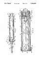
- FIG. 1is a side elevational view, partly in section, showing a needle shield and collar in accordance with a preferred embodiment of the invention secured to a conventional syringe with the shield in its retracted position;
- FIG. 2is an enlarged sectional view with the shield in cross-section in its extended position
- FIG. 3is a further enlarged partial side sectional view showing details of the collar and shield
- FIG. 4is a sectional view along the line 4-4 of FIG. 2 with the shield pulled to its extended position but before rotation;
- FIG. 5is a sectional view along the line 4-4 of FIG. 2 showing the shield rotated into its locked position
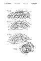
- FIG. 6is a perspective view of a preferred embodiment of the collar
- FIG. 7is a perspective view of an alternative embodiment of the collar.
- FIG. 8is a top sectional view showing the shield in its locked position with the shield shown in FIG. 7;
- FIG. 9is a side sectional view showing a collar construction for use with a large diameter barrel
- FIG. 10is a perspective view showing a needle shield and a collar according to a second embodiment of the invention secured to a conventional syringe with the shield in its retracted position;
- FIG. 11is a sectional view of the shield according to a further embodiment of the invention with the shield in its extended position;
- FIG. 12is a partial perspective view of the shield of the embodiment illustrated in FIG. 11;
- FIG. 13is a side view, partly in section, showing the needle shield and collar according to the embodiment illustrated in FIG. 11 with the shield in its retracted position;
- FIG. 14is a perspective view showing the details of the collar of the embodiment illustrated in FIG. 11, with part of a shield, shown in phantom, in its retracted position and without the locking tab;
- FIG. 15is a perspective view of the collar according to the embodiment illustrated in FIG. 11 with part of the shield, shown in phantom in its extended, but unlocked, position;
- FIG. 16is a perspective view of the collar according to the embodiment illustrated in FIG. 11 showing part of the shield (in phantom), in its extended and locked position;
- FIG. 17is a sectional view of the embodiment illustrated in FIG. 11 taken generally along line 17--17 of FIG. 13 with the shield pulled to its extended position but before rotation in accordance with the third embodiment;
- FIG. 18is a sectional view of the embodiment illustrated in FIG. 11 taken generally along the line 18--18 of FIG. 13 showing the shield rotated into its locked position in accordance with the third embodiment;
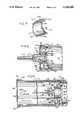
- FIG. 19is an enlarged partial perspective sectional view showing the details of a locking mechanism and a shield according to a further embodiment of the invention.
- FIGS. 20a, 20b and 20care sectional views of the shield according to a further embodiment of the invention illustrated in FIG. 19 showing the sequence for locking the shield in its extended position;
- FIG. 21is an enlarged partial side sectional view along the line 21--21 of FIG. 20c showing the shield in its locked position according to the embodiment of the invention illustrated in FIG. 19;
- FIG. 22is an enlarged partial top sectional view showing the details of a locking mechanism of a shield according to a further embodiment of the invention.
- FIG. 23is a sectional view taken generally along the line 23--23 of FIG. 22;
- FIG. 24is an enlarged partial side sectional view showing the details of the locking mechanism and a collar according to the embodiment of the invention illustrated in FIG. 22 with the shield in its extended but unlocked position;
- FIG. 25is an enlarged partial side sectional view showing the details of the locking mechanism and the collar according to the embodiment of the invention illustrated in FIG. 22 with the shield in its extended and locked position.
- the inventionis intended to be used in conjunction with a conventional syringe; however, a protective shield in accordance with the invention may be modified for use with nearly any medical or laboratory device having a needle, such as a blood collection tube holder with a double ended needle without departing from the contemplated scope of the present invention.
- a protective shield in accordance with the inventionmay be modified for use with nearly any medical or laboratory device having a needle, such as a blood collection tube holder with a double ended needle without departing from the contemplated scope of the present invention.
- the term "syringe”is intended to include any medical or scientific device including a needle wherein it is desired to protect a user from accidental needle sticks.
- distal end or forward end of a partrefers to the end of the part closest to the needle point.
- proximal end of a partrefers to the end of the part furthest from the needle point.
- FIGS. 1-6show a conventional syringe comprising a tubular barrel 10 having a finger flange 11, a plunger 12 slidable within the barrel 10, and a needle assembly through which the contents of the barrel are dispensed when the plunger 12 is depressed.
- the barrel 10may be tapered very slightly (not shown) from a larger diameter proximal end to a smaller diameter distal end for primarily molding purposes.
- the needle assemblycomprises a needle 14 and a hub 16 at the proximal end of the needle.
- a conically shaped luer tip 17 and luer lock skirt 18are integrally formed at the distal end of the barrel 10 with the luer lock skirt 18 encircling the luer tip 17.
- the interior surface of the luer lock skirt 18may include an internal thread 18A adapted to threadably engage complementary locking ears 16A on the needle hub 16.
- the exterior surface of luer lock skirt 18may include a multiplicity of ribs 19 parallel to the central axis of the barrel 10.
- a needle sheath 20covers the needle 14 as a protective device.
- the needle sheath 20frictionally engages the hub 16 and can be used to disconnect the needle assembly from the luer lock skirt 18 in a conventional fashion.
- the collar employed in accordance with the preferred embodiment of the inventionis shown generally at 22 (FIGS. 2 and 6).
- collar 22is shown as a separate piece made of differing materials, it is anticipated that the collar (or its functional equivalent) may be integrally formed as a part of the barrel 10 without substantial modification of the present invention.
- the collar 22includes six equally spaced and integrally formed identical triangular protrusions 24, with the apex of each protrusion extending away from the needle. Keyways 25 are formed between each adjacent pair of protrusions 24.
- the triangular protrusions 24each include angled surfaces 24A and 24B, side surfaces 25C, a slot 26 and a stop surface 27 which is generally circumferential and functions as a stop for the keys as further described below.
- the slot 26includes an inwardly sloped distal surface 26A. It is not absolutely necessary that the protrusions 24 be triangular in shape and it is anticipated that other configurations may be used to guide the keys into the keyways during the assembly process as described below.
- the slot 26is formed in protrusion 24 for retaining the detent 50 therein when the shield 40 is in the retracted position, as explained below.
- two walls 28 and 30extend toward the needle.
- a rectangular locking slot 31is formed between each pair of walls 28 and 30, which are ramp shaped in cross section as shown most clearly in FIGS. 4 and 5.
- the surface of locking slot 31is slightly elevated relative to the level of the keyways, i.e., the barrel diameter at the locking slots 31 is slightly greater than the barrel diameter at the keyways.
- the slight increase in the collar diameter at the locking slotsremoves some of the slack between the needle shield (described below) and the collar 22 resulting from the slight lengthwise taper of the barrel 10 in the preferred embodiment. This prevents or at least minimizes wobble or play of the shield when it is locked in the extended position.
- a spherical detent 32is positioned between each pair of triangular protrusions 24 with the distal edge of the detents 32 lying just in front of the bases of triangular projections 24.
- the proximal end of collar 22includes a peripheral rigid internal tooth 34 adapted to engage the ribs 19 in the luer lock skirt 18 and retain the collar 22 on the syringe.
- Collar 22is molded of a rigid plastic material such as polycarbonate resin so that when the collar is pushed over the luer lock skirt 18, the angled surface of the rigid tooth 34 allows the tooth to move over the ribs 19 until the proximal end of the collar is seated adjacent to the distal end of the barrel with the rigid tooth 34 deforming the ribs 19 of the luer lock skirt 18 to permanently retain the collar in place on the syringe barrel 10.
- a circumferential groovemay be formed in the outer surface of the luer lock skirt 18 to receive the peripheral tooth 34 of the collar 22 therein. This is unnecessary in the preferred embodiment in which the yieldable ribs 19 cold flow into the configuration shown in FIG. 3 but may be desirable in the case of syringes which do not include ribs molded on the exterior surface of the luer lock skirt.
- other fastening meanssuch as ultrasonic welding or adhesives may be used within the scope of the invention, although such techniques are generally disadvantageous because of the additional steps involved and other problems which may arise with the preferred assembly techniques.
- the diameter of collar 22 as measured in the area of the keyways 25is greater than the outer diameter of the syringe barrel 10 adjacent to the collar 22.
- the rigid tooth 34will bite sufficiently into the outer surface of the luer skirt 18 to prevent axial movement of collar 22 but in some cases slight rotation of the collar may occur.
- the tooth 34may be formed with gaps (not shown) so that not all of the ribs 19 on the outside of the luer lock skirt 18 will be deformed. The non-deformed ribs 19 will fall into the gaps of the tooth 34 resist rotation of the collar 22 relative to barrel 10.
- the inner surface of collar 22may be provided with lugs 35 molded on the inside of the collar and adapted to fit between the ribs 19 on the outside of the luer lock skirt 18 to prevent any rotational movement with the meshed ribs 19.
- the needle shield 40comprises an elongated plastic cylinder (e.g., made of polypropylene) having three keys 42 integrally formed on its interior surface.
- An end rim 44is formed at the proximal end of shield 40. As shown in FIG. 2, the end rim 44 is adapted to abut against the proximal end of collar 22 to limit the distal movement of the shield 40.
- Each of the keys 42includes a distal triangular point 46 and extends from the distal end of the shield to a location just short of the distal point of the triangular protrusions 24 on collar 22 when the shield is in the extended position as shown in FIG. 2.
- the end rim 44includes three cutout sections 45 which align with each of the keys 42.
- the cutout sections 45facilitate the process for molding keys 42 but serve no functional purpose after the device has been assembled.
- the keys 42terminate in flat end surfaces 48.
- rotational movement of the shield 40is prevented by contact between the edges of keys 42 against the side surfaces 24C of protrusions 24; therefore, torque can be applied to the needle while holding shield 40 to thread (or unthread) needles onto (or from) the syringe without having to grasp the barrel 10. This cannot be done with constructions in which a shield rotates freely with respect to the syringe.
- detents 50are also formed on the inner surface of the shield 40 toward its distal end. These detents 50 may be equally spaced and are adapted to be received within the slots 26 in the triangular protrusions 24 to releasably retain the shield 40 in its retracted position (FIG. 1). In the preferred embodiment, as shown in the drawings, the detents 50 are preferably spaced approximately thirty degrees from an adjacent key 42. Each of the detents 50 includes a sloped distal surface 50A and a proximal surface 50B more gradually sloped than distal surface 50A.
- Cap 52is molded from a resilient plastic material (such as polyallomer) and includes a side wall 53 and an end wall 54 which is adapted to be positioned between the distal end of collar 22 and the proximal end of the needle sheath 20 (FIG. 1) for substantially closing the distal end of shield 40.
- Side wall 53is shaped as shown so that end cap 52 can be retained on shield 40 by the interlocking mechanical engagement of the side wall 53 and a complementary projection 55 at the distal end of shield 40.
- the end wall 54includes a central needle aperture which is made small enough that the end of shield 40 is closed to the maximum extent while allowing the locking ears 16A of needle hub 16 to be extended through the aperture to permit needles to be mounted and removed while the shield 40 is in its retracted position.
- the apertureis not, however, large enough to allow the proximal end of the needle sheath 20 to pass through it. The use of the smaller sized needle aperture reduces the likelihood that a child or person with small fingers may accidentally contact the needle point.
- the end cap 52also makes the distal end of shield 40 more rigid and resistive to deformation when dropped or otherwise impacted upon a hard surface.
- the rim 54 and its position between the proximal end of needle sheath 20 and the distal end of barrel 10serves a functional purpose when removing or installing needles on the luer tip 17, for example, in a situation where the filling and injection needles are different.
- the syringeis held by shield 40 with the shield 40 in the retracted position.
- Needle hub 16, which projects from the proximal end of the protective sheath 20,is inserted through the aperture in the end wall 54 and the needle hub 16 is telescoped onto the luer tip 17.
- the needle hub 16is rotated by twisting and pushing with the sheath to thread the locking tabs 16A within the internal threads 18A in the luer skirt 18 until needle 14 is mounted on the syringe.
- the needlemoves axially relative to sheath 20.
- the shield 40is prevented from rotating by the abutment of keys 42 against the side surfaces 24C of protrusions 24, while the rim 54 provides a surface against which the needle sheath 20 can be forced.
- the end wall 54is particularly important when the invention is used in conjunction with large diameter syringe barrels.
- the preferred type of construction for the larger diameter syringe barrelsis shown in FIGS. 8 and 9 wherein like numerals are used to identify parts similar to those shown in the embodiment of FIGS. 1-6.
- the needle 15 and hub 16are the same as in FIG. 1 as is the luer tip 17 and the luer lock skirt 18.
- the collar 122includes two concentric sleeves 124 and 126 supported by an annular strut 128 forming an I-beam in cross-section as shown in FIG. 9.
- the end cap 152includes side wall 153 and end wall 154 which, as shown, covers a substantial portion of the barrel opening and thus greatly reduces the risk of accidental needle stick when the shield is in its extended position.
- the deviceis preferably assembled as follows. Shield 40 is inserted on the distal end of the barrel 10 of an assembled syringe and moved to the retracted position shown in FIG. 1 (with the needle 14 and sheath 20 removed). With the shield 40 held in the retracted position, the collar 22 is placed over the luer lock skirt 18 and inside of the shield 40. As the triangular protrusions 24 on collar 22 contact the triangular points 46 at the end of keys 42 on shield 40, the collar 22 is pushed onto the luer lock skirt 18 causing the shield 40 to rotate until the keys 46 are positioned in the keyways over the detents 32 located between the adjacent triangular protrusions 24.
- the collar 22is then pushed inwardly until the proximal end of the collar 22 butts up against the distal face 36 on the syringe barrel. In this position, as shown in FIG. 3, the three detents 50 are seated in the slots 26 of three of the protrusions 24. After the shield 40 and collar 22 have been assembled on the syringe, the end cap 52 is placed on the shield 40. Finally, the needle 14 with its sheath 20 may then be attached to the luer tip 17 to complete the assembly of the present invention.
- the collar 22may initially be positioned within shield 40 with the keys 42 positioned in the appropriate keyways 25.
- the shield 40 and collar 22may then be telescoped together over the syringe barrel 10 with the collar 22 being forced onto the luer lock skirt 18 as the shield 40 is moved to the retracted position wherein the proximal end of the collar 22 abuts against the distal face 36 of the syringe barrel 10.
- the alternative assembly methodmay be used with an open shield wherein the end cap 52 may be placed on the shield after assembly.
- the syringe of the present inventionmay be used in a conventional manner.
- the needle sheath 20is removed from the needle 14 and the medication is drawn into barrel 10 by withdrawing the plunger 12 from the distal end of the syringe while the shield is in its retracted position as shown in FIG. 1.
- the shield 40is pulled distally into the extended position as shown in FIG. 2.
- the keys 42slide in the keyways 25 over the spherical detents 32 between the adjacent protrusions 24 on collar 22 (FIG. 4) and the distal surfaces 50A of the detents 50 on the shield 40 slide onto the surfaces 26A of slots 26.
- the usercan feel the end surfaces 48 of keys 42 clearing the spherical detents 32, which signals that the shield 40 is fully extended.
- the userrotates the shield 40 to cause the keys 42 to move over the adjacent ramp surfaces 28 (or 30) until the keys fall into the locking slots 31 formed between each pair of ramps 28 and 30 (see FIG. 5). Because of the arrangement of the ramps 28 and 30, the shield can be locked by rotating it either clockwise or counterclockwise.
- the proximal edge 48 of each keyabuts against the squared off stop surface 27 of one of the triangular protrusions 24 so that the shield 40 cannot be returned to its retracted position without the application of excessive force to the shield 40. Because of the interlocking relationship between the square key 42 and the locking slots 31, the shield 40 can no longer be rotated and, accordingly, the shield is permanently locked in the extended position.
- the shield 40may be desirable to extend the shield 40 to the position shown in FIG. 2 without locking it in place.
- a syringeis to be filled at a location remote from the patient, rather than replacing the sheath 20 after the syringe is filled, it is preferable to extend shield 40 so that it functions as a temporary protective element while the syringe is carried to the patient.
- the use of the protective shield 40 in this fashionis facilitated by the spherical detents 32 on the collar 22. These spherical detents 32 are positioned in each of the keyways 25 between the triangular protrusions 24 so that when the shield 40 is pulled to its extended position (FIG.
- the flat end surface 48 of each of the keys 42abut against one of the spherical detents 32. This prevents the shield 40, when it is in its extended position, from being retracted unless sufficient force is applied to move the keys 42 over the spherical detents 32. Hence, in this situation, the shield 40 is first extended as a temporary sheath for the needle and then returned to its retracted position for administration of the patient's injection. Once the injection has been administered, the shield may again be extended and then locked by rotation so that the shield cannot be retracted.
- the gradual slope of surface 50B of detent 50allows the detent to be pushed over the squared off stop surface 27 prior to returning the shield to its fully retracted position.
- FIGS. 10 through 18A further embodiment of the present invention is shown in FIGS. 10 through 18.
- an L-shaped trigger member 56is incorporated on the distal or needle end of the shield 40.
- the longitudinal portion 58 of the L-shape formed by the trigger member 56is preferably curved to follow the contours of the shield 40.
- the trigger member 56is attached to the shield 40 by a hinge web 60 so that a transverse portion 62 of the L-shape formed by the trigger member 56 extends perpendicularly outward from shield 40.
- the trigger member 56is preferably incorporated with the mold of shield 40 and preferably includes a hinge web 60 which is essentially a smaller width extension of the longitudinal portion 58 of the trigger member 56.
- the material used to make shield 40is resilient so that the trigger member 56 can be moved following an arc centered around the hinge web 60, without damage, from an initial rest position where the longitudinal portion 58 of the trigger member 56 aligns with the walls of shield 40, to either an inner position or an outer position by rotating the trigger member 56 in an inward or an outward direction, with respect to the shield 40.
- An inward directionis the direction defined when the longitudinal portion 58 of the trigger member 56 is moved around the hinge web 60 into the interior of the shield 40.
- An outward directionis defined when the longitudinal portion 58 of trigger member 56 is moved around the hinge web 60 outside of the shield 40.
- FIG. 11shows the relative position of the trigger member 56 and shield 40 with the trigger member 56 in the outward position after the latch 70 has released the collar retaining ridge 72.
- An end flange 64projects radially outward around the perimeter of the shield 40 at its distal end.
- An extension 63 of this end flange 64projects further from the surface of the shield 40 just below and preferably parallel to the transverse portion 62 of the trigger member 56 in its rest position so that a stop point is established to limit the outward movement of the trigger member 56.
- a pair of recesses (detents) 66are disposed along the inside wall of shield 40 across from the hinge web 60. The recesses 66 limit the inward movement of the trigger member 56, as further described below.
- a pair of locking ears 68are located at the top of the longitudinal portion 58 of the trigger member 56 and are aligned with the recesses 66.
- the overall length of the longitudinal portion 58 of trigger member 56, including the locking ears 68,is slightly longer than the inner diameter of the shield 40 measured from the hinge web 60 to the recesses 66.
- the locking ears 68 of the longitudinal portion 58engage the recesses 66 on the inner surface of the shield 40.
- the locking ears 68 and the recesses 66are shaped so that engagement of the ears 68 with the recesses 66 provides an irreversibly locked arrangement which prevents any outward or further inward movement of the trigger member 56.
- the trigger member 56is locked in an extreme inward position so that the normally open needle end of the shield 40 is covered by the locked longitudinal portion 58 of trigger member 56.
- This locked portioncovers the normally open needle end of the shield 40 to prevent accidental or intentional contact with the needle tip through the open end of the shield.
- An opening 69is created in the side of the shield 40 after the longitudinal portion 58 of the trigger member 56 has been moved inwardly to its locked extreme. This opening 69 is then blocked by the transverse portion 62 of the trigger member 56 when it is moved to an axial position and lies within the opening 69 in the shield 40.
- the now axial transverse portion 62aligns with the contours of shield 40 and substantially protects and prevents the user from contacting the needle tip through the opening 69 which is temporarily uncovered by the relocated longitudinal portion 58.
- trigger member 56When trigger member 56 is in its initial position with the longitudinal portion 58 following the contours of shield 40 and shield 40 is in its fully retracted position as shown in FIG. 10, latch 70 engages with a collar retaining ridge 72 shown in FIG. 13 to prevent movement of the shield 40 with respect to the syringe barrel 10. It is readily anticipated that the trigger member 56 of the present embodiment is readily adaptable for use with any of the preferred shield locking mechanisms described herein and represents an additional means for protecting the open end of the shield.
- the shield 40can be slid to its extended position once the latch 70 is released from engagement with the collar retaining ridge 72. Outward movement by the trigger member 56 disengages the latch 70 from the retaining ridge 72 of the collar 22 and allows the shield 40 to be slid into its extended position, as shown in FIG. 11. Outward movement of the trigger member 58 is achieved by pressing the transverse portion 62 down until it is stopped by the extension 63 of the end flange 64. If the shield 40 is to be kept in its fully extended position after the injection has been given, the trigger member 58 can than be moved inwardly to its extreme inward position so that the locking ears 68 engages the recesses 66, as described above. The syringe 10 can now be discarded in a conventional manner with the contaminated needle fully protected by the locked shield 40 and the locked trigger member 56.
- FIG. 12generally illustrates the preferred form of the shield 40 which may be used individually or with the trigger member 56 wherein the shield 40 may be locked in the extended position and the trigger member 56 will be spaced apart from the distal end of the needle to prevent access to the needle through the open end of the shield 40.
- FIGS. 14 through 18further illustrate the shield locking arrangement located on the collar 22 in accordance with the present invention.
- Formed onto the surface of the collar 22are several operational members which are described in detail below.
- the key 42follows a longitudinal path parallel to the needle along the inside wall of the shield and guides the shield 40 as it slides along the collar 22.
- the key 42prevents rotation of the shield 40 relative to the syringe barrel 10 (including the collar) until the shield 40 is in its fully extended position.
- the key 42slides in a key channel 74 provided in the surface of the collar 22 which is preferably located near the proximal end of the collar 22.
- a key block 73lies adjacent to the key channel 74 near the proximal end of the collar 22 and supports the shield 40 as it is slid past the collar 22 and also forms a stop point for the key 42 to prevent proximal movement of the shield 40 when the shield is locked in the extended position as described further below (the term "locked” is used herein with respect to the shield 40 to describe the prevention of further linear or rotational movement between the shield 40 and the collar 22).
- the shield 40cannot be rotated during its travel to the fully extended position along the collar until the shield 40 has reached the fully extended position due to sliding contact between the key 42 and the key channel 74 of the collar 22.
- the length of the key 42is shorter than the length of the shield 40 so that the proximal end of the key exits the key channel 74 only when the shield 40 is fully extended. When this occurs, the shield 40 is no longer guided by the key 42 engagement with the key channel 74 and is free to rotate with respect to the collar 22 and the syringe barrel 10.
- a locking recess 78is located adjacent to the key channel 74 and a ramp 80 and an entry channel 84 are located near the proximal end of the collar 22.
- the relative positions of the key 42, the locking tab 82 and the securing block 76 along the inside wall of the shield 40 and the positions of the key channel 74, the key block 73 and the locking recess 78dictate the locking sequence for locking the shield 40 to the collar 22.
- the locking tab 82is positioned along the inner wall of the shield 40 so that an inwardly extending projection 83 on the locking tab 82 aligns with the entry channel 84 and will engage the entry channel 84 at the point when the shield 40 is fully extended.
- the entry channel 84is shaped so that the engaged inward projection 83, and therefore the shield 40, cannot be extended further.
- the entry channel 84does not, however, prevent the inward projection 83 and the shield 40 from returning to the retracted direction (re-exposing the needle) while the locking tab 82 is positioned in the entry channel 84 (FIG. 15).
- the entry channel 84is preferably wider than the width of the locking tab 82 as measured circumferentially along the collar 22 and the shield 40, respectively.
- the shield 40is rotated counter-clockwise until the inward projection 83 of the locking tab 82 leaves the entry channel 84, travels up the inclined ramp 80 and drops into the locking recess 78.
- the end of the keyhas become misaligned with the key channel 74 and is now positioned adjacent to the distal side of the key block 73 and the securing block 76 is positioned adjacent to the proximal side of the key block 73 to prevent longitudinal movement of the shield 40 about the collar 22.
- the shieldwhich must be rotated clockwise to realign the key with the key channel 74 in order for it to be retracted, is prevented from any rotation due to the inward projection 83 of the locking tab 82 being securely engaged in the locking recess 78.
- the shield 40is now locked in its extended position and cannot be returned to the retracted position without applying excessive force to the shield 40.
- a key alignment taper 88 and a locking tab insertion ramp 90are illustrated along the lower edge of the collar 22 to assist in the assembly of the present invention by aligning the key into the key channel 74 and to Q initially insert the locking tab 82 over the collar 22 and into the entry channel 84.
- the securing block 76is oriented above and slightly offset from the end of the key 42. The securing block 76 operates in combination with the locking tab 82 to prevent the shield 40 from being removed from the collar 22 when the shield 40 has been rotated into the locked position.
- FIGS. 19-21A further embodiment of the present invention is shown in FIGS. 19-21.
- a key block 100is fixed to either a collar which is attached to the distal end of the syringe barrel 10 or to the syringe barrel directly (shown in phantom in FIG. 19).
- a key block channel 102is disposed along the inside wall of the shield 104 and accepts the key block 100.
- the shield 104can be slid along the syringe barrel 10 and guided by the key block 100 from a retracted position (the needle exposed) to an extended position (the needle protected).
- a locking channel 106is provided adjacent to the key block channel 102. The locking channel 106 accepts the key block 100 only when the key block 100 is located in a lockable position, as shown in FIG. 20B.
- the shield 104can be rotated so that the key block 100 moves into the locking channel 106.
- the locking channel 106preferably begins abruptly at the lockable position defined, in part, by a stop wall 108 against which the key block 100 abuts when it enters the locking channel 106 from the lockable position.
- a pair of spring biased stop ramps 110, 112are positioned in the key block channel 102. Both are formed preferably within the wall of the shield 104 and, are both, spring biased inwardly as shown in FIG. 19.
- Locking ramp 110has two inclined surfaces (as shown in FIG. 19), a distal surface 114, and a proximal surface 116, both of which are connected at a single cusp ridge 118 extending inwardly from the wall of the shield 104 and upwardly from the normally flat surface of the key block channel 102.
- the key block 100can be slid along either inclined surface 114 or 116 of the locking ramp 110 when the shield 104 is appropriately moved.
- the stop ramp 112is positioned adjacent to the locking ramp 110 and provides only one ramp surface (proximal) and a distal edge 120, thereby allowing movement in a single direction with respect to the key block 100 as further described below.
- the stop ramp 112is positioned adjacent to the locking ramp 110 so that the key block 100 will be prevented from passing the lockable position as the shield 104 is extended. There exists just enough room for the key block 100 to slide sideways into the locking channel 106 between the stop wall 108 and the distal edge 120 of the stop ramp 112 when the shield 104 is rotated with respect to the syringe.
- the proximal surface 116 of the stop ramp 112is useful primarily during assembly of the present invention to assist in connecting the shield 104 to the barrel of the syringe.
- the proximal surface 116 of the stop ramp 112allows the key block 100 to pass the locking ramp 110 during the assembly of the syringe. Otherwise, the locking ramp 110 would act as a one way ramp and resist the passage of the key block 100 over the locking ramp 110 and therefore prevent the shield 104 from passing over the cusp ridge 118.
- the key block 100when first inserted, travels along both the proximal surface 116 of the locking ramp 110 and the stop ramp 112, depressing them both.
- the key block 100cannot return and the shield 104 cannot be removed from the syringe barrel without the use of excessive force.
- the shield 104is slid forwardly from its retracted position to its fully extended position.
- the key block 100slides proximally in the key block channel 102 to the distal surface 114 of the locking ramp 110 and slightly depresses the distal surface 114 of the locking ramp 110 until the key block 100 contacts the distal edge 120 of the stop ramp 112.
- the key block 100 and shield 40are in a lockable extended position and the needle is protected by the surrounding shield 104 which is freely slidable to the retracted position.
- the shield 104is rotated about the syringe barrel 10 so that the key block 100 moves from the lockable position to the locked position within the locking channel 106.
- the key block 100enters the locking channel 106 (FIG. 20C)
- itleaves the distal surface 114 of the locking ramp 110 which, owing to its resilient nature springs upwardly. (towards the barrel).
- the key block 100then becomes locked on all four sides, by the side edge of the distal surface 114; the stop wall 108; the shield body 104; and the distal edge of the stop ramp 112.
- the side edge of the distal surface 114prevents the key block 100 from re-entering the key block channel 102 and therefore, prevents the shield from returning to its retracted position.
- FIGS. 22-25Yet another shield locking arrangement of the present invention is shown in FIGS. 22-25.
- a collar 140is provided and attached to the distal end of a syringe barrel 10.
- the shield 144includes a channel 146 incorporated along its side wall.
- the channel 146is defined by an outer surface 148 and two supporting walls 150.
- the outer surface 148is substantially parallel to the surface of the syringe barrel 10.
- a depressible locking tab 152is formed in the outer surface 148 of the shield, above the channel 146.
- the locking tab 152is secured to the shield 144 by a first hinge web 154.
- a second hinge web 156is provided adjacent and parallel to the first hinge web 154 on the proximal end of the locking tab 152.
- the locking tab 152includes a locking edge 153 which is parallel to the hinge webs (154, 156) and is positioned on the proximal end of the locking tab 152.
- the locking tab 152normally follows the contours of the outer surface 148 of the channel 146 until it is pushed into its locked position which is further described below.
- a rib 151projects outwardly from the locking tab 152 to provide a leverage point for pushing the tab 152 into its locked position, as shown in FIG. 24.
- a guide key 164extends outwardly from the collar 140 and is attached directly to the distal end of the syringe barrel.
- the guide key 164is a block-like projection extending outwardly from the surface of the collar 140 and is shaped so that it can slide longitudinally within the channel 146 without excessive radial movement while controlling the sliding movement of the shield along the syringe barrel.
- the guide key 164includes a locking flange 166 along its distal (closest to the needle) upper edge.
- the locking flange 166lies parallel to and inwardly from the inner surface of the channel 146 to define a locking space 168 between the collar 140 and the underside (side closest to the collar) of the projecting locking flange 166, adjacent to the distal surface of the guide key 164 (FIG. 24).
- a pair of opposing retaining hooks 170Disposed within the supporting walls 150 of the channel 146 are a pair of opposing retaining hooks 170 which project inwardly towards each other into the channel 146.
- the hooks 170are preferably located near the proximal end of the shield 144.
- the hooks 170are spring biased into the channel 146 and are shaped so that shield 144 can pass the guide key 164 in only one direction, the shield 144 cannot be removed from the syringe barrel after the guide key 164 of the collar 140 is initially slid past the retaining hooks 170.
- the shield 144is moveable from a retracted position (needle exposed) to an extended position (needle covered) and will remain in the extended position when it is locked as further described below.
- the retaining hooks 170are positioned along the shield 144 so that when the shield 144 is fully extended, the retaining hooks 170 will contact the proximal surface of the guide key 164 and prevent further extending movement of the shield 144. At this point the shield is in a lockable position.
- the locking edge 153 of the locking tab 152is located above the channel 146 in the shield 144 so that when the shield 144 is in the lockable position the locking edge 153 remains in an overlapping position with respect to the locking flange 166 of the guide key 164.
- the locking tab 152may then be depressed inwardly towards the syringe barrel 10, tearing any frangible points which kept the locking tab 152 aligned with the contours of the shield 144.
- the proximal overlapping locking edge 153is supported by the locking flange 166 and directs the inward force against the locking tab 152 distally to bend the locking tab 152 at both hinge web points 154 and 156.
- the bending of the locking tab 152 at the hinge webs 154 and 156forces the locking edge 153 to move distally.
- the locking edge 153will eventually slide off the locking flange 166 and snap inwardly to contact the inner surface of the locking flange 166 on the collar 140.
- the resilient nature of the shield materialsprings the hinge webs proximally to move the locking edge 153 into the locking space 168 to lock the shield 144 in the extended position adjacent to the collar 140.
- the locking edge 153 of the locking tab 152will contact the locking space 168 of the guide key 164 to prevent further proximal movement of the shield about the barrel. Movement to retract the shield will force the distal part of the locking tab 152 inwardly, against the action of the hinge webs 154 and 156, the locking flange 166 will retain the locking edge 153 therein and prevent it from moving from the locked position.
- the hinge webs 154 and 156will move the distal part of the locking tab 152 inwardly until contact is made between the surfaces of the collar 140 and the underside of the locking tab 152.
- the locking tab 152is illustrated in the lockable position in FIG. 24 and the locked position in FIG. 25.
Landscapes
- Health & Medical Sciences (AREA)
- Engineering & Computer Science (AREA)
- Life Sciences & Earth Sciences (AREA)
- Animal Behavior & Ethology (AREA)
- Anesthesiology (AREA)
- Biomedical Technology (AREA)
- Heart & Thoracic Surgery (AREA)
- Hematology (AREA)
- Environmental & Geological Engineering (AREA)
- Vascular Medicine (AREA)
- General Health & Medical Sciences (AREA)
- Public Health (AREA)
- Veterinary Medicine (AREA)
- Infusion, Injection, And Reservoir Apparatuses (AREA)
- Medicinal Preparation (AREA)
- Finger-Pressure Massage (AREA)
- Impact Printers (AREA)
Abstract
Description
Claims (11)
Priority Applications (16)
| Application Number | Priority Date | Filing Date | Title |
|---|---|---|---|
| US07/364,939US5156599A (en) | 1988-06-28 | 1989-06-09 | Syringe and sliding locking needle shield |
| CA000603478ACA1324937C (en) | 1988-06-28 | 1989-06-21 | Combined syringe and needle shield and method of manufacture |
| AT89306399TATE94076T1 (en) | 1988-06-28 | 1989-06-23 | SYRINGE CONNECTED TO A NEEDLE TUBE AND METHOD OF MANUFACTURE. |
| AT92201225TATE136797T1 (en) | 1988-06-28 | 1989-06-23 | SYRINGE CONNECTED TO A NEEDLE RUNNING AND METHOD FOR PRODUCING IT |
| EP92201225AEP0506204B1 (en) | 1988-06-28 | 1989-06-23 | Combined syringe and needle shield and method of manufacture |
| ES89306399TES2045439T3 (en) | 1988-06-28 | 1989-06-23 | A SYRINGE THAT HAS A RETRACTABLE NEEDLE GUARD AND MANUFACTURING METHOD. |
| DE89306399TDE68908975T2 (en) | 1988-06-28 | 1989-06-23 | Syringe connected to a needle sleeve and method of manufacture. |
| ES92201225TES2085550T3 (en) | 1988-06-28 | 1989-06-23 | COMBINED PROTECTOR FOR SYRINGE AND NEEDLE AND METHOD FOR ITS MANUFACTURE. |
| DE68926312TDE68926312T2 (en) | 1988-06-28 | 1989-06-23 | Syringe connected to a needle sleeve and method of manufacture |
| EP89306399AEP0350186B1 (en) | 1988-06-28 | 1989-06-23 | Combined syringe and needle shield and method of manufacture |
| DK198903154ADK173549B1 (en) | 1988-06-28 | 1989-06-26 | Needle protection means for use with a medical or scientific tool comprising a syringe cylinder, hypodermic injector |
| JP1165147AJP2916779B2 (en) | 1988-06-28 | 1989-06-27 | Composite syringe-needle shield device |
| AU37065/89AAU621127B2 (en) | 1988-06-28 | 1989-06-27 | Combined syringe and needle shield and method of manufacture |
| US07/806,949US5169392A (en) | 1988-06-28 | 1991-12-11 | Combined syringe and needle shield and method of manufacture |
| AU16055/92AAU641863B2 (en) | 1988-06-28 | 1992-05-06 | Needle shielding device |
| SG27294ASG27294G (en) | 1988-06-28 | 1994-02-21 | Combined syringe and needle shield and method of manufacture. |
Applications Claiming Priority (2)
| Application Number | Priority Date | Filing Date | Title |
|---|---|---|---|
| US07/212,528US5053018A (en) | 1988-06-28 | 1988-06-28 | Combined syringe and needle shield and method of manufacture |
| US07/364,939US5156599A (en) | 1988-06-28 | 1989-06-09 | Syringe and sliding locking needle shield |
Related Parent Applications (1)
| Application Number | Title | Priority Date | Filing Date |
|---|---|---|---|
| US07/212,528Continuation-In-PartUS5053018A (en) | 1988-06-28 | 1988-06-28 | Combined syringe and needle shield and method of manufacture |
Related Child Applications (2)
| Application Number | Title | Priority Date | Filing Date |
|---|---|---|---|
| US07422374Continuation-In-Part | 1989-10-16 | ||
| US07/806,949DivisionUS5169392A (en) | 1988-06-28 | 1991-12-11 | Combined syringe and needle shield and method of manufacture |
Publications (1)
| Publication Number | Publication Date |
|---|---|
| US5156599Atrue US5156599A (en) | 1992-10-20 |
Family
ID=26907229
Family Applications (1)
| Application Number | Title | Priority Date | Filing Date |
|---|---|---|---|
| US07/364,939Expired - Fee RelatedUS5156599A (en) | 1988-06-28 | 1989-06-09 | Syringe and sliding locking needle shield |
Country Status (9)
| Country | Link |
|---|---|
| US (1) | US5156599A (en) |
| EP (2) | EP0350186B1 (en) |
| JP (1) | JP2916779B2 (en) |
| AT (1) | ATE136797T1 (en) |
| AU (2) | AU621127B2 (en) |
| CA (1) | CA1324937C (en) |
| DE (2) | DE68926312T2 (en) |
| DK (1) | DK173549B1 (en) |
| ES (2) | ES2085550T3 (en) |
Cited By (96)
| Publication number | Priority date | Publication date | Assignee | Title |
|---|---|---|---|---|
| US5256153A (en)* | 1989-03-02 | 1993-10-26 | Hake Lawrence W | Hypodermic needle guard and method to prevent needle stick injuries |
| US5312370A (en)* | 1988-06-28 | 1994-05-17 | Sherwood Medical Company | Combined syringe and needle shield |
| US5314414A (en)* | 1989-03-02 | 1994-05-24 | Needlepoint Guard, Inc. | Hypodermic needle guard and method to prevent needle stick injuries |
| US5389083A (en)* | 1993-01-13 | 1995-02-14 | Jrm Enterprises, Inc. | Guards for hypodermic needle |
| US5651774A (en)* | 1996-09-11 | 1997-07-29 | William J. Taranto | Hypodermic syringe with safety shield and method of using same |
| US5669888A (en)* | 1992-07-31 | 1997-09-23 | Matef | Injection needle protection device |
| US5843041A (en)* | 1989-03-02 | 1998-12-01 | Hake; Lawrence W. | Hypodermic needle guard and method to prevent needle stick injuries |
| US5891099A (en)* | 1996-07-03 | 1999-04-06 | Togo Medikit Co., Ltd. | Disposal medical thrust device |
| US6017329A (en)* | 1989-03-02 | 2000-01-25 | Hake; Lawrence W. | Hypodermic needle guard and method to prevent needle stick injuries |
| KR20020088246A (en)* | 2001-05-19 | 2002-11-27 | 신현달 | Cylinder,needle and cap unified safety syringe. |
| WO2004093946A1 (en)* | 2003-04-16 | 2004-11-04 | Mallinckrodt Inc. | Radiation shield for a safety syringe having a needle sheath |
| US20050096598A1 (en)* | 2003-11-03 | 2005-05-05 | Becton, Dickinson And Company | Safety shield system for a syringe |
| US20050096597A1 (en)* | 2003-11-03 | 2005-05-05 | Becton, Dickinson And Company | Safety shield system for a syringe |
| US20050096599A1 (en)* | 2003-11-03 | 2005-05-05 | Becton, Dickinson & Company | Safety device for a syringe |
| US20050096596A1 (en)* | 2003-11-03 | 2005-05-05 | Becton, Dickinson And Company | Safety shield system for a syringe |
| US20050159709A1 (en)* | 2004-01-20 | 2005-07-21 | Becton, Dickinson And Company | Safety shield system for a plastic syringe |
| US20050159707A1 (en)* | 2004-01-20 | 2005-07-21 | Becton, Dickinson And Company | Syringe having a retractable needle |
| US20050159705A1 (en)* | 2004-01-20 | 2005-07-21 | Becton, Dickinson And Company | Syringe having a retractable needle |
| US20050159706A1 (en)* | 2004-01-20 | 2005-07-21 | Becton, Dickinson And Company | Medical syringe with safety shield system |
| US20060189933A1 (en)* | 2005-02-18 | 2006-08-24 | Becton, Dickinson And Company | Safety shield system for a syringe |
| GB2425062A (en)* | 2005-04-06 | 2006-10-18 | Cilag Ag Int | An injection device |
| US20070038184A1 (en)* | 2005-08-08 | 2007-02-15 | Bialecki Dennis M | Needle guard clip with lip |
| US20070038183A1 (en)* | 2005-08-08 | 2007-02-15 | Bialecki Dennis M | Needle guard clip with stylus |
| US20070038188A1 (en)* | 2005-08-08 | 2007-02-15 | Bialecki Dennis M | Duckbill catheter release mechanism |
| US20070073226A1 (en)* | 2005-09-23 | 2007-03-29 | John Polidoro | Syringe |
| US20070073222A1 (en)* | 2005-08-08 | 2007-03-29 | Lilley Thomas F Jr | Needle guard mechanism with angled strut wall |
| US20070112310A1 (en)* | 2003-07-31 | 2007-05-17 | Sid Technologies Llc | Injecting apparatus |
| US20070191776A1 (en)* | 2006-02-16 | 2007-08-16 | Medex, Inc. | Enclosed Needle Device with Duckbill Release Mechanism |
| US20090012470A1 (en)* | 2004-05-28 | 2009-01-08 | Cilag Ag Interntional | Injection Device |
| US20090105663A1 (en)* | 2007-10-11 | 2009-04-23 | Rexam Pharma La Verpilliere | Safety device for a liquid injection syringe, and a syringe assembly including the device |
| US20110172602A1 (en)* | 2008-09-02 | 2011-07-14 | Owen Mumford Limited | Syringe safety shields and autoinjector |
| US7985216B2 (en) | 2004-03-16 | 2011-07-26 | Dali Medical Devices Ltd. | Medicinal container engagement and automatic needle device |
| US20110202011A1 (en)* | 2008-08-28 | 2011-08-18 | Owen Mumford Limited | Autoinjection devices |
| US8057431B2 (en) | 2006-12-21 | 2011-11-15 | B. Braun Melsungen Ag | Hinged cap for needle device |
| US20120238962A1 (en)* | 2007-02-07 | 2012-09-20 | Chin Sin Fong | Safety Shield System for a Single Use Flexible-Type Compression Syringe, and Injection Device |
| US8277414B2 (en) | 2004-05-28 | 2012-10-02 | Cilag Gmbh International | Injection device |
| US8313465B2 (en) | 2004-05-28 | 2012-11-20 | Cilag Gmbh International | Injection device |
| US8313463B2 (en) | 2004-05-28 | 2012-11-20 | Cilag Gmbh International | Injection device |
| US8317751B2 (en) | 2005-04-06 | 2012-11-27 | Cilag Gmbh International | Injection device |
| US8323251B2 (en) | 2008-01-14 | 2012-12-04 | Fenwal, Inc. | Phlebotomy needle assembly and frangible cover |
| US8343110B2 (en) | 2004-05-28 | 2013-01-01 | Cilag Gmbh International | Injection device |
| US8366669B2 (en) | 2005-04-06 | 2013-02-05 | Cilag Gmbh International | Injection device |
| US8376998B2 (en) | 2003-09-17 | 2013-02-19 | Elcam Medical Agricultural Cooperative Association Ltd. | Automatic injection device |
| US20130066328A1 (en)* | 2011-04-07 | 2013-03-14 | Jai Singh | General uterine manipulator and system |
| US20130072893A1 (en)* | 2010-06-30 | 2013-03-21 | Terumo Kabushiki Kaisha | Connector and connector assembly |
| US20130197536A1 (en)* | 2011-04-07 | 2013-08-01 | Jai Singh | General uterine manipulator and system |
| US20140135706A1 (en)* | 2008-06-02 | 2014-05-15 | Sta-Med, Llc | Needle cover |
| US8834419B2 (en) | 2008-06-19 | 2014-09-16 | Cilag Gmbh International | Reusable auto-injector |
| US8845594B2 (en) | 2008-06-19 | 2014-09-30 | Cilag Gmbh International | Auto-injector with filling means |
| US8939958B2 (en) | 2008-06-19 | 2015-01-27 | Cilag Gmbh International | Fluid transfer assembly for a syringe |
| US8968236B2 (en) | 2005-04-06 | 2015-03-03 | Cilag Gmbh International | Injection device |
| US9028453B2 (en) | 2008-06-19 | 2015-05-12 | Cilag Gmbh International | Reusable auto-injector |
| US9028451B2 (en) | 2006-06-01 | 2015-05-12 | Cilag Gmbh International | Injection device |
| US9072833B2 (en) | 2006-06-01 | 2015-07-07 | Cilag Gmbh International | Injection device |
| US20160067410A1 (en)* | 2013-05-17 | 2016-03-10 | Carrtech Llc | Filtering Needle Cap |
| US20160081717A1 (en)* | 2011-04-07 | 2016-03-24 | Jai Singh | General uterine manipulator and system |
| US9358346B2 (en) | 2005-08-30 | 2016-06-07 | Cilag Gmbh International | Needle assembly for a prefilled syringe system |
| US9480464B2 (en) | 2011-07-29 | 2016-11-01 | New York University | Tissue collection system |
| US9532837B2 (en) | 2012-04-20 | 2017-01-03 | Jiwan Steven Singh | Repositionable medical instrument support systems, devices, and methods |
| US9555221B2 (en) | 2014-04-10 | 2017-01-31 | Smiths Medical Asd, Inc. | Constant force hold tip protector for a safety catheter |
| US20170112998A1 (en)* | 2007-10-02 | 2017-04-27 | Medimop Medical Projects Ltd. | Method of using a key to secure components of a drug delivery system during assembly |
| US9649441B2 (en) | 2005-04-06 | 2017-05-16 | Cilag Gmbh International | Injection device (bayonet cap removal) |
| US9675757B2 (en) | 2004-05-28 | 2017-06-13 | Cilag Gmbh International | Injection device |
| US9675758B2 (en) | 2004-05-28 | 2017-06-13 | Cilag Gmbh International | Injection device |
| US9682194B2 (en) | 2008-06-19 | 2017-06-20 | Cilag Gmbh International | Re-useable auto-injector with filling means |
| US9694140B2 (en) | 2010-06-23 | 2017-07-04 | Sta-Med, Llc | Automatic-locking safety needle covers and methods of use and manufacture |
| US20170203048A1 (en)* | 2002-02-11 | 2017-07-20 | Sanofi | Needle Sheathing Device With Flexible End-Piece For Syringe |
| US9757520B2 (en) | 2006-06-01 | 2017-09-12 | Cilag Gmbh International | Injection device |
| US9770558B2 (en) | 2005-09-27 | 2017-09-26 | Cilag Gmbh International | Auto-injection device with needle protecting cap having outer and inner sleeves |
| US9848810B2 (en) | 2011-05-31 | 2017-12-26 | Sta-Med, Llc | Blood collection safety devices and methods of use and manufacture |
| US9895493B2 (en) | 2004-05-28 | 2018-02-20 | Cilag Gmbh International | Injection device |
| US10709849B2 (en) | 2013-06-11 | 2020-07-14 | Cilag Gmbh International | Guide for an injection device |
| US10758679B2 (en) | 2015-05-29 | 2020-09-01 | West Pharma. Services IL, Ltd. | Linear rotation stabilizer for a telescoping syringe stopper driverdriving assembly |
| US10799646B2 (en) | 2013-06-11 | 2020-10-13 | Cilag Gmbh International | Injection device |
| US10912891B2 (en) | 2015-09-22 | 2021-02-09 | West Pharma. Services IL, Ltd. | Rotation resistant friction adapter for plunger driver of drug delivery device |
| WO2021025922A1 (en)* | 2019-08-02 | 2021-02-11 | Becton, Dickinson And Company | Variable length injection syringe |
| US10960131B2 (en) | 2007-10-02 | 2021-03-30 | West Pharma. Services IL, Ltd. | Apparatuses for securing components of a drug delivery system during transport and methods of using same |
| US11083841B2 (en) | 2002-08-09 | 2021-08-10 | Fenwal, Inc. | Needle protector, needle assembly and fluid processing set including the same |
| US11123492B2 (en) | 2013-06-11 | 2021-09-21 | Cilag Gmbh International | Injection device |
| US11173255B2 (en) | 2013-06-11 | 2021-11-16 | Cilag Gmbh International | Injection device |
| US11311674B2 (en) | 2016-01-21 | 2022-04-26 | West Pharma. Services IL, Ltd. | Medicament delivery device comprising a visual indicator |
| US11318254B2 (en) | 2015-10-09 | 2022-05-03 | West Pharma. Services IL, Ltd. | Injector needle cap remover |
| US11338090B2 (en) | 2016-08-01 | 2022-05-24 | West Pharma. Services IL, Ltd. | Anti-rotation cartridge pin |
| US11364337B2 (en) | 2016-01-21 | 2022-06-21 | West Pharma. Services IL, Ltd. | Force containment in an automatic injector |
| US11389597B2 (en) | 2016-03-16 | 2022-07-19 | West Pharma. Services IL, Ltd. | Staged telescopic screw assembly having different visual indicators |
| US11504481B2 (en) | 2007-10-02 | 2022-11-22 | West Pharma. Services IL, Ltd. | Anti-rotation feature for infusion pump cartridge |
| US11547802B2 (en) | 2015-10-09 | 2023-01-10 | West Pharma. Services IL, Ltd. | Angled syringe patch injector |
| US11672904B2 (en) | 2016-01-21 | 2023-06-13 | West Pharma. Services IL, Ltd. | Needle insertion and retraction mechanism |
| US11819666B2 (en) | 2017-05-30 | 2023-11-21 | West Pharma. Services IL, Ltd. | Modular drive train for wearable injector |
| US11857768B1 (en) | 2022-10-01 | 2024-01-02 | CARRTECH Corp. | Filtering needle assembly with seal plug |
| US11890459B2 (en) | 2020-03-27 | 2024-02-06 | Medivena Sp. Z O.O. | Needle-based device with external safety cap and a needle guide element thereof |
| US12017011B2 (en) | 2019-09-10 | 2024-06-25 | Medsource International Llc | Intravenous catheter device |
| WO2024086205A3 (en)* | 2022-10-19 | 2024-06-27 | Noble International, Llc | Plunger speed control injection system |
| US12186497B2 (en) | 2022-01-14 | 2025-01-07 | Medsource International Llc | Intravenous cannula |
| US12337123B2 (en) | 2021-05-06 | 2025-06-24 | Medsource Labs, Llc | Safety intravenous cannula |
| US12357767B2 (en) | 2016-08-01 | 2025-07-15 | West Pharma. Services IL, Ltd. | Partial door closure prevention spring |
Families Citing this family (35)
| Publication number | Priority date | Publication date | Assignee | Title |
|---|---|---|---|---|
| US5147326A (en)* | 1988-06-28 | 1992-09-15 | Sherwood Medical Company | Combined syringe and needle shield and method of manufacture |
| US5156599A (en)* | 1988-06-28 | 1992-10-20 | Sherwood Medical Company | Syringe and sliding locking needle shield |
| US5057087A (en)* | 1989-04-24 | 1991-10-15 | Harmon James E | Hypodermic needle safety system |
| WO1991011212A1 (en)* | 1990-02-02 | 1991-08-08 | Gerard Philip Gilliland | A retractable sharp |
| GB2240718A (en)* | 1990-02-09 | 1991-08-14 | Hundon Forge Ltd | Implanting device with needle cover |
| US5057089A (en)* | 1990-10-04 | 1991-10-15 | Greco Robert M | Syringe needle guard |
| US5376080A (en)* | 1991-01-30 | 1994-12-27 | Petrussa; Gian L. | Single use retractable needle syringe |
| IT1248125B (en)* | 1991-01-30 | 1995-01-05 | Gian Luigi Petrussa | CONCEALED NEEDLE DEVICE |
| US5259841A (en)* | 1991-02-25 | 1993-11-09 | Gemini Trade Overseas Ltd. | Safety syringe |
| US5306258A (en)* | 1991-04-03 | 1994-04-26 | Fuente Ricardo L De | Safety syringe and method of using same |
| WO1992018183A1 (en)* | 1991-04-15 | 1992-10-29 | Sherwood Medical Company | Combined syringe and needle shield |
| US5304149A (en)* | 1992-06-12 | 1994-04-19 | Becton, Dickinson And Company | Medical device with a lockable needle shield |
| US5496288A (en)* | 1992-09-23 | 1996-03-05 | Becton, Dickinson And Company | Protective cap for hypodermic syringe |
| ES2050619B1 (en)* | 1992-11-02 | 1994-11-16 | Alvarez Redondo S A | SAFETY PROTECTOR FOR HYPODERMIC NEEDLES. |
| US5328473A (en)* | 1993-04-28 | 1994-07-12 | Becton, Dickinson And Company | Disposable needle holder |
| US5385557A (en)* | 1994-04-04 | 1995-01-31 | Thompson; Clarence J. | Shielding device for a syringe needle |
| FR2719775B1 (en)* | 1994-05-11 | 1996-09-20 | Assist Publ Hopitaux De Paris | Safety needle device for syringe comprising such a device. |
| WO1996029107A1 (en)* | 1995-03-17 | 1996-09-26 | Radiometer Medical A/S | Shielding means |
| US5658254A (en)* | 1995-03-31 | 1997-08-19 | Becton, Dickinson And Company | Syringe having safety needle shield |
| US5697908A (en)* | 1996-09-26 | 1997-12-16 | Becton Dickinson France, S.A. | Lockable safety shield for a prefillable syringe |
| US5733264A (en)* | 1997-01-22 | 1998-03-31 | Becton, Dickinson And Company | Shieldable syringe assembly |
| US5980494A (en)* | 1997-12-22 | 1999-11-09 | Robert Malenchek | Safety syringe |
| WO1999051289A1 (en)* | 1998-04-01 | 1999-10-14 | Jireh Tech Pty. Ltd. | Needle stick protection apparatus |
| DE20006251U1 (en)* | 2000-04-05 | 2001-08-16 | B D Medico Gmbh, Mies | Needle guard assembly |
| DE10044383C2 (en)* | 2000-09-08 | 2003-02-06 | Disetronic Licensing Ag | Needle protector |
| US6945958B2 (en) | 2001-11-14 | 2005-09-20 | Sherwood Services Ag | Safety needle apparatus |
| US6527742B1 (en) | 2001-11-14 | 2003-03-04 | Robert C. Malenchek | Safety syringe |
| US20040039340A1 (en)* | 2001-12-28 | 2004-02-26 | Becton, Dickinson And Company | Shieldable unit dose medical needle assemblies |
| DE60336743D1 (en) | 2002-10-17 | 2011-05-26 | Mallinckrodt Inc | DEVICE FOR TRANSPORTING LIQUID RADIOPHARMACEUTICS AND THE ASSOCIATED METHOD AND MANUFACTURING METHOD THEREOF |
| WO2004041332A1 (en)* | 2002-11-04 | 2004-05-21 | Sergio Restelli | Set of components for making a syringe into a disposable automatic safety syringe and relative disposable automatic safety syringe |
| US6926697B2 (en) | 2003-05-13 | 2005-08-09 | Robert Malenchek | Adaptor for converting a non-safety syringe into a safety syringe |
| AU2003903633A0 (en)* | 2003-07-15 | 2003-07-31 | Medical Safety Devices Pty Ltd | Improved syringe safety device |
| US8425460B2 (en) | 2005-09-01 | 2013-04-23 | Owen Mumford Limited | Needle shroud assembly |
| BR112012019101A2 (en) | 2010-02-05 | 2016-09-13 | Sanofi Aventis Deutschland | drug module with dual use button and drug delivery system. |
| CN103025371B (en)* | 2010-07-02 | 2015-04-08 | 赛诺菲-安万特德国有限公司 | Safety devices and injection devices for prefilled syringes |
Citations (50)
| Publication number | Priority date | Publication date | Assignee | Title |
|---|---|---|---|---|
| US2571653A (en)* | 1950-02-25 | 1951-10-16 | Bastien Victor Gerard | Syringe |
| US3780734A (en)* | 1971-12-10 | 1973-12-25 | G Wulff | Hypodermic syringe holder and injector device |
| US3890071A (en)* | 1973-09-24 | 1975-06-17 | Brien William J O | Rotary steam engine |
| DE2833804A1 (en)* | 1977-09-02 | 1979-03-15 | Island S R L | DEVICE FOR AUTOMATIC ADMINISTRATION OF SUBcutaneous injections |
| US4170993A (en)* | 1978-03-13 | 1979-10-16 | Marcial Alvarez | Sliding I.V. needle carrier assembly |
| US4356822A (en)* | 1980-10-17 | 1982-11-02 | Winstead Hall Deborah | Syringe assembly |
| US4425129A (en)* | 1981-12-07 | 1984-01-10 | Colgate-Palmolive Company | Diaper with cushioned elastic leg hold edges |
| US4573976A (en)* | 1984-05-24 | 1986-03-04 | Dolores A. Smith | Shielded needle |
| DE8606355U1 (en)* | 1986-03-06 | 1986-08-28 | PHYSIONIC Gesellschaft für Medizin- und Systemtechnik mbH, 1000 Berlin | Injection cannula protection |
| US4631057A (en)* | 1985-12-17 | 1986-12-23 | Dolores A. Smith | Shielded needle |
| US4643200A (en)* | 1986-03-27 | 1987-02-17 | Jennings Jr Baldwin P | Safety blood donor apparatus |
| US4643199A (en)* | 1986-02-28 | 1987-02-17 | Jennings Jr Baldwin P | Safety blood sample apparatus |
| US4650468A (en)* | 1986-02-26 | 1987-03-17 | Jennings Jr Baldwin P | Medical syringe |
| EP0216460A1 (en)* | 1985-07-29 | 1987-04-01 | National Research Development Corporation | Safety device for hypodermic needle or the like |
| US4655751A (en)* | 1986-02-14 | 1987-04-07 | Harbaugh John T | Liquid dispensing and receiving syringe |
| US4666435A (en)* | 1986-05-22 | 1987-05-19 | Braginetz Paul A | Shielded medical syringe |
| DE3609516C1 (en)* | 1985-10-11 | 1987-06-04 | Physionic Ges Fuer Medizin Und | Injection syringe |
| US4681567A (en)* | 1986-04-03 | 1987-07-21 | Masters Edwin J | Syringe with safety sheath |
| US4693708A (en)* | 1986-10-16 | 1987-09-15 | Wanderer Alan A | Combination needle shield/needle guard device for a hypodermic syringe with a permanently attached needle |
| US4695274A (en)* | 1986-01-31 | 1987-09-22 | Fox Richard L | Protected hypodermic needle |
| EP0240987A2 (en)* | 1986-04-07 | 1987-10-14 | ICU Medical, Inc. | Medical device |
| US4702738A (en)* | 1986-05-22 | 1987-10-27 | Spencer Treesa A | Disposable hypodermic syringe and needle combination having retractable, accident preventing sheath |
| EP0252644A2 (en)* | 1986-07-09 | 1988-01-13 | Erbamont, Inc. | Method and apparatus for catching fluids purged from a syringe |
| US4723943A (en)* | 1986-12-31 | 1988-02-09 | Montana Deaconess Medical Center | Sheathed syringe |
| US4737144A (en)* | 1987-03-09 | 1988-04-12 | Choksi Pradip V | Syringe with selectively exposed and enveloped needle |
| US4738663A (en)* | 1987-06-04 | 1988-04-19 | Bogan David B | Hypodermic needle shield |
| US4743233A (en)* | 1986-01-23 | 1988-05-10 | Schneider Medical Technologies, Inc. | Safety cap syringe |
| US4840185A (en)* | 1988-02-17 | 1989-06-20 | Manuel Hernandez | Blood sampling device with shield |
| US4842587A (en)* | 1987-07-15 | 1989-06-27 | Poncy George W | No-prick hypodermic syringe |
| US4871355A (en)* | 1988-05-17 | 1989-10-03 | Steven Kikkawa | Injury resistant needle and blood collection tube holder |
| US4874383A (en)* | 1987-03-17 | 1989-10-17 | Mcnaughton R David | Syringe shield |
| US4892523A (en)* | 1987-04-27 | 1990-01-09 | Habley Medical Technology Corporation | Shielded safety syringe |
| US4894055A (en)* | 1988-12-28 | 1990-01-16 | Sudnak Paul J | Needle guard assembly for use with hypodermic syringes and the like |
| US4900311A (en)* | 1988-12-06 | 1990-02-13 | Lawrence Stern | Hypodermic syringe |
| US4908023A (en)* | 1988-08-15 | 1990-03-13 | Frank Yuen | Syringe assembly |
| US4917673A (en)* | 1988-10-31 | 1990-04-17 | Coplin Allan J | Assembly for the protection against inadvertent puncture by medical needles |
| US4923445A (en)* | 1988-03-01 | 1990-05-08 | Ryan Medical, Inc. | Safety needled medical devices |
| US4923447A (en)* | 1989-02-17 | 1990-05-08 | Morgan Michael W | Syringe assembly |
| US4932940A (en)* | 1988-06-06 | 1990-06-12 | Walker Cedric F | Needle guard device |
| US4935016A (en)* | 1988-02-17 | 1990-06-19 | Deleo John | Syringe |
| US4976702A (en)* | 1989-04-17 | 1990-12-11 | Serad, Inc. | Syringe needle guard |
| US4994045A (en)* | 1990-04-20 | 1991-02-19 | Sherwood Medical Company | Split sleeve safety syringe |
| US4998924A (en)* | 1989-07-25 | 1991-03-12 | Sherwood Medical Company | Double sleeve safety syringe |
| US5011479A (en)* | 1989-10-06 | 1991-04-30 | Son Le | Cover and connector for hypodermic needle |
| US5019049A (en)* | 1990-02-20 | 1991-05-28 | Haining Michael L | Intravenous catheter and insertion device |
| US5019051A (en)* | 1989-03-02 | 1991-05-28 | Needlepoint Guard, Inc. | Hypodermic needle guard |
| US5024616A (en)* | 1988-11-15 | 1991-06-18 | International Medication Systems, Limited | Disposable sheath for hypodermic cannula used with a syringe |
| US5030209A (en)* | 1988-11-09 | 1991-07-09 | Medical Safety Products, Inc. | Holder for double ended blood collection retractable needle |
| US5029660A (en)* | 1990-04-06 | 1991-07-09 | Ford Motor Company | Steering control method and control system for wheeled vehicles |
| US5045066A (en)* | 1990-06-07 | 1991-09-03 | Smith & Nephew, Inc. | Dental needle with stick resistant protective sleeve |
Family Cites Families (2)
| Publication number | Priority date | Publication date | Assignee | Title |
|---|---|---|---|---|
| US4731059A (en)* | 1986-10-14 | 1988-03-15 | Medical Safety Products, Inc. | Combination needle shield/needle guard device positively locked onto detachable needle assemblies for an evacuated blood collection system and a hypodermic syringe |
| US5156599A (en)* | 1988-06-28 | 1992-10-20 | Sherwood Medical Company | Syringe and sliding locking needle shield |
- 1989
- 1989-06-09USUS07/364,939patent/US5156599A/ennot_activeExpired - Fee Related
- 1989-06-21CACA000603478Apatent/CA1324937C/ennot_activeExpired - Lifetime
- 1989-06-23ESES92201225Tpatent/ES2085550T3/ennot_activeExpired - Lifetime
- 1989-06-23EPEP89306399Apatent/EP0350186B1/ennot_activeExpired - Lifetime
- 1989-06-23DEDE68926312Tpatent/DE68926312T2/ennot_activeExpired - Lifetime
- 1989-06-23DEDE89306399Tpatent/DE68908975T2/ennot_activeExpired - Fee Related
- 1989-06-23EPEP92201225Apatent/EP0506204B1/ennot_activeExpired - Lifetime
- 1989-06-23ESES89306399Tpatent/ES2045439T3/ennot_activeExpired - Lifetime
- 1989-06-23ATAT92201225Tpatent/ATE136797T1/ennot_activeIP Right Cessation
- 1989-06-26DKDK198903154Apatent/DK173549B1/ennot_activeIP Right Cessation
- 1989-06-27AUAU37065/89Apatent/AU621127B2/ennot_activeCeased
- 1989-06-27JPJP1165147Apatent/JP2916779B2/ennot_activeExpired - Fee Related
- 1992
- 1992-05-06AUAU16055/92Apatent/AU641863B2/ennot_activeCeased
Patent Citations (51)
| Publication number | Priority date | Publication date | Assignee | Title |
|---|---|---|---|---|
| US2571653A (en)* | 1950-02-25 | 1951-10-16 | Bastien Victor Gerard | Syringe |
| US3780734A (en)* | 1971-12-10 | 1973-12-25 | G Wulff | Hypodermic syringe holder and injector device |
| US3890071A (en)* | 1973-09-24 | 1975-06-17 | Brien William J O | Rotary steam engine |
| DE2833804A1 (en)* | 1977-09-02 | 1979-03-15 | Island S R L | DEVICE FOR AUTOMATIC ADMINISTRATION OF SUBcutaneous injections |
| US4170993A (en)* | 1978-03-13 | 1979-10-16 | Marcial Alvarez | Sliding I.V. needle carrier assembly |
| US4356822A (en)* | 1980-10-17 | 1982-11-02 | Winstead Hall Deborah | Syringe assembly |
| US4425129A (en)* | 1981-12-07 | 1984-01-10 | Colgate-Palmolive Company | Diaper with cushioned elastic leg hold edges |
| US4573976A (en)* | 1984-05-24 | 1986-03-04 | Dolores A. Smith | Shielded needle |
| EP0216460A1 (en)* | 1985-07-29 | 1987-04-01 | National Research Development Corporation | Safety device for hypodermic needle or the like |
| DE3609516C1 (en)* | 1985-10-11 | 1987-06-04 | Physionic Ges Fuer Medizin Und | Injection syringe |
| US4631057A (en)* | 1985-12-17 | 1986-12-23 | Dolores A. Smith | Shielded needle |
| US4743233A (en)* | 1986-01-23 | 1988-05-10 | Schneider Medical Technologies, Inc. | Safety cap syringe |
| US4695274A (en)* | 1986-01-31 | 1987-09-22 | Fox Richard L | Protected hypodermic needle |
| US4655751A (en)* | 1986-02-14 | 1987-04-07 | Harbaugh John T | Liquid dispensing and receiving syringe |
| US4650468A (en)* | 1986-02-26 | 1987-03-17 | Jennings Jr Baldwin P | Medical syringe |
| US4643199A (en)* | 1986-02-28 | 1987-02-17 | Jennings Jr Baldwin P | Safety blood sample apparatus |
| DE8606355U1 (en)* | 1986-03-06 | 1986-08-28 | PHYSIONIC Gesellschaft für Medizin- und Systemtechnik mbH, 1000 Berlin | Injection cannula protection |
| US4643200A (en)* | 1986-03-27 | 1987-02-17 | Jennings Jr Baldwin P | Safety blood donor apparatus |
| US4681567A (en)* | 1986-04-03 | 1987-07-21 | Masters Edwin J | Syringe with safety sheath |
| EP0240987A2 (en)* | 1986-04-07 | 1987-10-14 | ICU Medical, Inc. | Medical device |
| US4666435A (en)* | 1986-05-22 | 1987-05-19 | Braginetz Paul A | Shielded medical syringe |
| US4702738A (en)* | 1986-05-22 | 1987-10-27 | Spencer Treesa A | Disposable hypodermic syringe and needle combination having retractable, accident preventing sheath |
| EP0250104A1 (en)* | 1986-05-22 | 1987-12-23 | Treesa A. Spencer | Disposable hypodermic syringe and needle combination having retractable, accident preventing sheath |
| EP0252644A2 (en)* | 1986-07-09 | 1988-01-13 | Erbamont, Inc. | Method and apparatus for catching fluids purged from a syringe |
| US4693708A (en)* | 1986-10-16 | 1987-09-15 | Wanderer Alan A | Combination needle shield/needle guard device for a hypodermic syringe with a permanently attached needle |
| US4723943A (en)* | 1986-12-31 | 1988-02-09 | Montana Deaconess Medical Center | Sheathed syringe |
| US4737144A (en)* | 1987-03-09 | 1988-04-12 | Choksi Pradip V | Syringe with selectively exposed and enveloped needle |
| US4874383A (en)* | 1987-03-17 | 1989-10-17 | Mcnaughton R David | Syringe shield |
| US4892523A (en)* | 1987-04-27 | 1990-01-09 | Habley Medical Technology Corporation | Shielded safety syringe |
| US4738663A (en)* | 1987-06-04 | 1988-04-19 | Bogan David B | Hypodermic needle shield |
| US4842587A (en)* | 1987-07-15 | 1989-06-27 | Poncy George W | No-prick hypodermic syringe |
| US4840185A (en)* | 1988-02-17 | 1989-06-20 | Manuel Hernandez | Blood sampling device with shield |
| US4935016A (en)* | 1988-02-17 | 1990-06-19 | Deleo John | Syringe |
| US4923445A (en)* | 1988-03-01 | 1990-05-08 | Ryan Medical, Inc. | Safety needled medical devices |
| US4871355A (en)* | 1988-05-17 | 1989-10-03 | Steven Kikkawa | Injury resistant needle and blood collection tube holder |
| US4932940A (en)* | 1988-06-06 | 1990-06-12 | Walker Cedric F | Needle guard device |
| US4908023A (en)* | 1988-08-15 | 1990-03-13 | Frank Yuen | Syringe assembly |
| US4917673A (en)* | 1988-10-31 | 1990-04-17 | Coplin Allan J | Assembly for the protection against inadvertent puncture by medical needles |
| US5030209A (en)* | 1988-11-09 | 1991-07-09 | Medical Safety Products, Inc. | Holder for double ended blood collection retractable needle |
| US5024616A (en)* | 1988-11-15 | 1991-06-18 | International Medication Systems, Limited | Disposable sheath for hypodermic cannula used with a syringe |
| US4900311A (en)* | 1988-12-06 | 1990-02-13 | Lawrence Stern | Hypodermic syringe |
| US4894055A (en)* | 1988-12-28 | 1990-01-16 | Sudnak Paul J | Needle guard assembly for use with hypodermic syringes and the like |
| US4923447A (en)* | 1989-02-17 | 1990-05-08 | Morgan Michael W | Syringe assembly |
| US5019051A (en)* | 1989-03-02 | 1991-05-28 | Needlepoint Guard, Inc. | Hypodermic needle guard |
| US4976702A (en)* | 1989-04-17 | 1990-12-11 | Serad, Inc. | Syringe needle guard |
| US4998924A (en)* | 1989-07-25 | 1991-03-12 | Sherwood Medical Company | Double sleeve safety syringe |
| US5011479A (en)* | 1989-10-06 | 1991-04-30 | Son Le | Cover and connector for hypodermic needle |
| US5019049A (en)* | 1990-02-20 | 1991-05-28 | Haining Michael L | Intravenous catheter and insertion device |
| US5029660A (en)* | 1990-04-06 | 1991-07-09 | Ford Motor Company | Steering control method and control system for wheeled vehicles |
| US4994045A (en)* | 1990-04-20 | 1991-02-19 | Sherwood Medical Company | Split sleeve safety syringe |
| US5045066A (en)* | 1990-06-07 | 1991-09-03 | Smith & Nephew, Inc. | Dental needle with stick resistant protective sleeve |
Cited By (155)
| Publication number | Priority date | Publication date | Assignee | Title |
|---|---|---|---|---|
| US5312370A (en)* | 1988-06-28 | 1994-05-17 | Sherwood Medical Company | Combined syringe and needle shield |
| US5403287A (en)* | 1988-06-28 | 1995-04-04 | Sherwood Medical Company | Endcap and shield assembly for a shielded safety syringe |
| US5522812A (en)* | 1988-06-28 | 1996-06-04 | Sherwood Medical Company | Combined dental syringe and needle shield |
| US6017329A (en)* | 1989-03-02 | 2000-01-25 | Hake; Lawrence W. | Hypodermic needle guard and method to prevent needle stick injuries |
| US5314414A (en)* | 1989-03-02 | 1994-05-24 | Needlepoint Guard, Inc. | Hypodermic needle guard and method to prevent needle stick injuries |
| US5256153A (en)* | 1989-03-02 | 1993-10-26 | Hake Lawrence W | Hypodermic needle guard and method to prevent needle stick injuries |
| US5843041A (en)* | 1989-03-02 | 1998-12-01 | Hake; Lawrence W. | Hypodermic needle guard and method to prevent needle stick injuries |
| US5669888A (en)* | 1992-07-31 | 1997-09-23 | Matef | Injection needle protection device |
| US5389083A (en)* | 1993-01-13 | 1995-02-14 | Jrm Enterprises, Inc. | Guards for hypodermic needle |
| US5891099A (en)* | 1996-07-03 | 1999-04-06 | Togo Medikit Co., Ltd. | Disposal medical thrust device |
| US5651774A (en)* | 1996-09-11 | 1997-07-29 | William J. Taranto | Hypodermic syringe with safety shield and method of using same |
| KR20020088246A (en)* | 2001-05-19 | 2002-11-27 | 신현달 | Cylinder,needle and cap unified safety syringe. |
| US20170203048A1 (en)* | 2002-02-11 | 2017-07-20 | Sanofi | Needle Sheathing Device With Flexible End-Piece For Syringe |
| US11135377B2 (en)* | 2002-02-11 | 2021-10-05 | Sanofi | Needle sheathing device with flexible end-piece for syringe |
| US11083841B2 (en) | 2002-08-09 | 2021-08-10 | Fenwal, Inc. | Needle protector, needle assembly and fluid processing set including the same |
| US7452324B2 (en) | 2003-04-16 | 2008-11-18 | Mallinckrodt Inc. | Radiation shield for a safety syringe having a needle sheath |
| WO2004093946A1 (en)* | 2003-04-16 | 2004-11-04 | Mallinckrodt Inc. | Radiation shield for a safety syringe having a needle sheath |
| US20060195061A1 (en)* | 2003-04-16 | 2006-08-31 | Quent Besing | Radiation shield for a safety syringe having a needle sheath |
| US7717877B2 (en)* | 2003-07-31 | 2010-05-18 | Sid Technologies, Llc | Injecting apparatus |
| US20070112310A1 (en)* | 2003-07-31 | 2007-05-17 | Sid Technologies Llc | Injecting apparatus |
| US11623051B2 (en) | 2003-09-17 | 2023-04-11 | E3D Agricultural Cooperative Association Ltd. | Automatic injection device |
| US8376998B2 (en) | 2003-09-17 | 2013-02-19 | Elcam Medical Agricultural Cooperative Association Ltd. | Automatic injection device |
| EP2650033A2 (en) | 2003-09-17 | 2013-10-16 | Elcam Medical Agricultural Cooperative Association Ltd. | Automatic injection device |
| US20050096599A1 (en)* | 2003-11-03 | 2005-05-05 | Becton, Dickinson & Company | Safety device for a syringe |
| US20050096596A1 (en)* | 2003-11-03 | 2005-05-05 | Becton, Dickinson And Company | Safety shield system for a syringe |
| US7101351B2 (en) | 2003-11-03 | 2006-09-05 | Becton, Dickinson And Company | Safety device for a syringe |
| US7468054B2 (en) | 2003-11-03 | 2008-12-23 | Becton, Dickinson And Company | Safety shield system for a syringe |
| US7497847B2 (en) | 2003-11-03 | 2009-03-03 | Becton, Dickinson And Company | Safety shield system for a syringe |
| US20050096597A1 (en)* | 2003-11-03 | 2005-05-05 | Becton, Dickinson And Company | Safety shield system for a syringe |
| US20050096598A1 (en)* | 2003-11-03 | 2005-05-05 | Becton, Dickinson And Company | Safety shield system for a syringe |
| US20050159707A1 (en)* | 2004-01-20 | 2005-07-21 | Becton, Dickinson And Company | Syringe having a retractable needle |
| US20050159706A1 (en)* | 2004-01-20 | 2005-07-21 | Becton, Dickinson And Company | Medical syringe with safety shield system |
| US20050159705A1 (en)* | 2004-01-20 | 2005-07-21 | Becton, Dickinson And Company | Syringe having a retractable needle |
| US7604613B2 (en) | 2004-01-20 | 2009-10-20 | Beckton, Dickinson And Company | Syringe having a retractable needle |
| US7344517B2 (en) | 2004-01-20 | 2008-03-18 | Becton, Dickinson And Company | Syringe having a retractable needle |
| US20050159709A1 (en)* | 2004-01-20 | 2005-07-21 | Becton, Dickinson And Company | Safety shield system for a plastic syringe |
| US7985216B2 (en) | 2004-03-16 | 2011-07-26 | Dali Medical Devices Ltd. | Medicinal container engagement and automatic needle device |
| US9675757B2 (en) | 2004-05-28 | 2017-06-13 | Cilag Gmbh International | Injection device |
| US20090012470A1 (en)* | 2004-05-28 | 2009-01-08 | Cilag Ag Interntional | Injection Device |
| US8343110B2 (en) | 2004-05-28 | 2013-01-01 | Cilag Gmbh International | Injection device |
| US8313463B2 (en) | 2004-05-28 | 2012-11-20 | Cilag Gmbh International | Injection device |
| US9895493B2 (en) | 2004-05-28 | 2018-02-20 | Cilag Gmbh International | Injection device |
| US8313464B2 (en) | 2004-05-28 | 2012-11-20 | Cilag Gmbh International | Injection device |
| US8313465B2 (en) | 2004-05-28 | 2012-11-20 | Cilag Gmbh International | Injection device |
| US9675758B2 (en) | 2004-05-28 | 2017-06-13 | Cilag Gmbh International | Injection device |
| US8277414B2 (en) | 2004-05-28 | 2012-10-02 | Cilag Gmbh International | Injection device |
| US8062252B2 (en) | 2005-02-18 | 2011-11-22 | Becton, Dickinson And Company | Safety shield system for a syringe |
| US20060189933A1 (en)* | 2005-02-18 | 2006-08-24 | Becton, Dickinson And Company | Safety shield system for a syringe |
| GB2425062B (en)* | 2005-04-06 | 2010-07-21 | Cilag Ag Int | Injection device |
| US8317751B2 (en) | 2005-04-06 | 2012-11-27 | Cilag Gmbh International | Injection device |
| US9649441B2 (en) | 2005-04-06 | 2017-05-16 | Cilag Gmbh International | Injection device (bayonet cap removal) |
| US8366669B2 (en) | 2005-04-06 | 2013-02-05 | Cilag Gmbh International | Injection device |
| GB2425062A (en)* | 2005-04-06 | 2006-10-18 | Cilag Ag Int | An injection device |
| US8968236B2 (en) | 2005-04-06 | 2015-03-03 | Cilag Gmbh International | Injection device |
| US9731080B2 (en) | 2005-04-06 | 2017-08-15 | Cilag Gmbh International | Injection device |
| US20070038182A1 (en)* | 2005-08-08 | 2007-02-15 | Bialecki Dennis M | Needle guard mechanism with needle support |
| US20070073221A1 (en)* | 2005-08-08 | 2007-03-29 | Bialecki Dennis M | Needle guard mechanism with leaf spring |
| US7632243B2 (en) | 2005-08-08 | 2009-12-15 | Smiths Medical Asd, Inc. | Duckbill catheter release mechanism |
| US20070038187A1 (en)* | 2005-08-08 | 2007-02-15 | Albert Sean J | Needle guard mechanism with anti-rotation feature |
| US20070038184A1 (en)* | 2005-08-08 | 2007-02-15 | Bialecki Dennis M | Needle guard clip with lip |
| US8162881B2 (en) | 2005-08-08 | 2012-04-24 | Smiths Medical Asd, Inc. | Needle guard mechanism with angled strut wall |
| US20070073222A1 (en)* | 2005-08-08 | 2007-03-29 | Lilley Thomas F Jr | Needle guard mechanism with angled strut wall |
| US20070038183A1 (en)* | 2005-08-08 | 2007-02-15 | Bialecki Dennis M | Needle guard clip with stylus |
| US20070038188A1 (en)* | 2005-08-08 | 2007-02-15 | Bialecki Dennis M | Duckbill catheter release mechanism |
| US8403886B2 (en) | 2005-08-08 | 2013-03-26 | Smiths Medical Asd, Inc. | Needle guard clip with lip |
| US8647301B2 (en) | 2005-08-08 | 2014-02-11 | Smiths Medical Asd, Inc. | Safety catheter device with removably attached housing |
| US9358346B2 (en) | 2005-08-30 | 2016-06-07 | Cilag Gmbh International | Needle assembly for a prefilled syringe system |
| US20070073226A1 (en)* | 2005-09-23 | 2007-03-29 | John Polidoro | Syringe |
| US9770558B2 (en) | 2005-09-27 | 2017-09-26 | Cilag Gmbh International | Auto-injection device with needle protecting cap having outer and inner sleeves |
| US7658725B2 (en) | 2006-02-16 | 2010-02-09 | Smiths Medical Asd, Inc. | Enclosed needle device with duckbill release mechanism |
| US20070191776A1 (en)* | 2006-02-16 | 2007-08-16 | Medex, Inc. | Enclosed Needle Device with Duckbill Release Mechanism |
| US9072833B2 (en) | 2006-06-01 | 2015-07-07 | Cilag Gmbh International | Injection device |
| US9028451B2 (en) | 2006-06-01 | 2015-05-12 | Cilag Gmbh International | Injection device |
| US9757520B2 (en) | 2006-06-01 | 2017-09-12 | Cilag Gmbh International | Injection device |
| US8715231B2 (en) | 2006-12-21 | 2014-05-06 | B. Braun Melsungen Ag | Hinged cap for needle device |
| US8057431B2 (en) | 2006-12-21 | 2011-11-15 | B. Braun Melsungen Ag | Hinged cap for needle device |
| US9623192B2 (en)* | 2007-02-07 | 2017-04-18 | Becton, Dickinson And Company | Safety shield system for a single use flexible-type compression syringe, and injection device |
| US20120238962A1 (en)* | 2007-02-07 | 2012-09-20 | Chin Sin Fong | Safety Shield System for a Single Use Flexible-Type Compression Syringe, and Injection Device |
| US11504481B2 (en) | 2007-10-02 | 2022-11-22 | West Pharma. Services IL, Ltd. | Anti-rotation feature for infusion pump cartridge |
| US20170112998A1 (en)* | 2007-10-02 | 2017-04-27 | Medimop Medical Projects Ltd. | Method of using a key to secure components of a drug delivery system during assembly |
| US10960131B2 (en) | 2007-10-02 | 2021-03-30 | West Pharma. Services IL, Ltd. | Apparatuses for securing components of a drug delivery system during transport and methods of using same |
| US10420880B2 (en) | 2007-10-02 | 2019-09-24 | West Pharma. Services IL, Ltd. | Key for securing components of a drug delivery system during assembly and/or transport and methods of using same |
| US10716890B2 (en)* | 2007-10-02 | 2020-07-21 | West Pharma. Services IL, Ltd. | Method of using a key to secure components of a drug delivery system during assembly |
| US11590291B2 (en) | 2007-10-02 | 2023-02-28 | West Pharma. Services IL, Ltd. | External drug pump |
| US20090105663A1 (en)* | 2007-10-11 | 2009-04-23 | Rexam Pharma La Verpilliere | Safety device for a liquid injection syringe, and a syringe assembly including the device |
| US9675765B2 (en)* | 2007-10-11 | 2017-06-13 | Rexam Pharma La Verpilliere | Safety device for a liquid injection syringe, and a syringe assembly including the device |
| US8870828B2 (en) | 2008-01-14 | 2014-10-28 | Fenwal, Inc. | Phlebotomy needle assembly and frangible cover |
| US8323251B2 (en) | 2008-01-14 | 2012-12-04 | Fenwal, Inc. | Phlebotomy needle assembly and frangible cover |
| US11090443B2 (en) | 2008-06-02 | 2021-08-17 | Sta-Med, Llc | Needle cover |
| US20140135706A1 (en)* | 2008-06-02 | 2014-05-15 | Sta-Med, Llc | Needle cover |
| US10335554B2 (en)* | 2008-06-02 | 2019-07-02 | Sta-Med, Llc | Needle cover |
| US11992665B2 (en) | 2008-06-02 | 2024-05-28 | Sta-Med, Llc | Needle cover |
| US8939958B2 (en) | 2008-06-19 | 2015-01-27 | Cilag Gmbh International | Fluid transfer assembly for a syringe |
| US9028453B2 (en) | 2008-06-19 | 2015-05-12 | Cilag Gmbh International | Reusable auto-injector |
| US8834419B2 (en) | 2008-06-19 | 2014-09-16 | Cilag Gmbh International | Reusable auto-injector |
| US8845594B2 (en) | 2008-06-19 | 2014-09-30 | Cilag Gmbh International | Auto-injector with filling means |
| US9682194B2 (en) | 2008-06-19 | 2017-06-20 | Cilag Gmbh International | Re-useable auto-injector with filling means |
| US20110202011A1 (en)* | 2008-08-28 | 2011-08-18 | Owen Mumford Limited | Autoinjection devices |
| US9242053B2 (en)* | 2008-08-28 | 2016-01-26 | Owen Mumford Limited | Autoinjection devices |
| US20110172602A1 (en)* | 2008-09-02 | 2011-07-14 | Owen Mumford Limited | Syringe safety shields and autoinjector |
| US8932254B2 (en)* | 2008-09-02 | 2015-01-13 | Owen Mumford Limited | Syringe safety shields and autoinjector |
| US9694140B2 (en) | 2010-06-23 | 2017-07-04 | Sta-Med, Llc | Automatic-locking safety needle covers and methods of use and manufacture |
| US11992666B2 (en) | 2010-06-23 | 2024-05-28 | Sta-Med, Llc | Automatic-locking safety needle covers and methods of use and manufacture |
| US10682470B2 (en) | 2010-06-23 | 2020-06-16 | Sta-Med, Llc | Automatic-locking safety needle covers and methods of use and manufacture |
| US20130072893A1 (en)* | 2010-06-30 | 2013-03-21 | Terumo Kabushiki Kaisha | Connector and connector assembly |
| US9101390B2 (en)* | 2011-04-07 | 2015-08-11 | Jai Singh | General uterine manipulator and system |
| US10792072B2 (en) | 2011-04-07 | 2020-10-06 | Jai Singh | General uterine manipulator and system |
| US20130197536A1 (en)* | 2011-04-07 | 2013-08-01 | Jai Singh | General uterine manipulator and system |
| US9987042B2 (en)* | 2011-04-07 | 2018-06-05 | Jai Singh | General uterine manipulator and system |
| US20150012009A1 (en)* | 2011-04-07 | 2015-01-08 | Jai Singh | General uterine manipulator and system |
| US9974567B2 (en) | 2011-04-07 | 2018-05-22 | Jiwan Steven Singh | General uterine manipulator and system |
| US20130066328A1 (en)* | 2011-04-07 | 2013-03-14 | Jai Singh | General uterine manipulator and system |
| US9451985B2 (en) | 2011-04-07 | 2016-09-27 | Jiwan Steven Singh | General uterine manipulator and system |
| US20160081717A1 (en)* | 2011-04-07 | 2016-03-24 | Jai Singh | General uterine manipulator and system |
| US9848810B2 (en) | 2011-05-31 | 2017-12-26 | Sta-Med, Llc | Blood collection safety devices and methods of use and manufacture |
| US12274550B2 (en) | 2011-05-31 | 2025-04-15 | Sta-Med, Llc | Blood collection safety devices and methods of use and manufacture |
| US11116432B2 (en) | 2011-05-31 | 2021-09-14 | Sta-Med, Llc | Blood collection safety devices and methods of use and manufacture |
| US9480464B2 (en) | 2011-07-29 | 2016-11-01 | New York University | Tissue collection system |
| US10004569B2 (en) | 2012-04-20 | 2018-06-26 | Jiwan Steven Singh | Repositionable medical instrument support systems, devices, and methods |
| US9532837B2 (en) | 2012-04-20 | 2017-01-03 | Jiwan Steven Singh | Repositionable medical instrument support systems, devices, and methods |
| US20160067410A1 (en)* | 2013-05-17 | 2016-03-10 | Carrtech Llc | Filtering Needle Cap |
| US10512728B2 (en) | 2013-05-17 | 2019-12-24 | Carrtech Llc | Filtering needle cap with a seal around a needle |
| US9669164B2 (en)* | 2013-05-17 | 2017-06-06 | Carrtech Llc | Filtering needle cap having a sleeve sealing around a needle |
| US11123492B2 (en) | 2013-06-11 | 2021-09-21 | Cilag Gmbh International | Injection device |
| US10709849B2 (en) | 2013-06-11 | 2020-07-14 | Cilag Gmbh International | Guide for an injection device |
| US10799646B2 (en) | 2013-06-11 | 2020-10-13 | Cilag Gmbh International | Injection device |
| US11173255B2 (en) | 2013-06-11 | 2021-11-16 | Cilag Gmbh International | Injection device |
| US9555221B2 (en) | 2014-04-10 | 2017-01-31 | Smiths Medical Asd, Inc. | Constant force hold tip protector for a safety catheter |
| US10758679B2 (en) | 2015-05-29 | 2020-09-01 | West Pharma. Services IL, Ltd. | Linear rotation stabilizer for a telescoping syringe stopper driverdriving assembly |
| US10912891B2 (en) | 2015-09-22 | 2021-02-09 | West Pharma. Services IL, Ltd. | Rotation resistant friction adapter for plunger driver of drug delivery device |
| US12036394B2 (en) | 2015-10-09 | 2024-07-16 | West Pharma. Services IL, Ltd. | Injector needle cap and/or liner remover |
| US11547802B2 (en) | 2015-10-09 | 2023-01-10 | West Pharma. Services IL, Ltd. | Angled syringe patch injector |
| US12208246B2 (en) | 2015-10-09 | 2025-01-28 | West Pharma. Services IL, Ltd. | Bent fluid path add on to a prefilled fluid reservoir |
| US11318254B2 (en) | 2015-10-09 | 2022-05-03 | West Pharma. Services IL, Ltd. | Injector needle cap remover |
| US12138429B2 (en) | 2015-10-09 | 2024-11-12 | West Pharma. Services IL, Ltd. | Angled syringe patch injector |
| US11724034B2 (en) | 2015-10-09 | 2023-08-15 | West Pharma. Services, IL, Ltd. | Injector system |
| US11759573B2 (en) | 2015-10-09 | 2023-09-19 | West Pharma. Services, IL, Ltd. | Bent fluid path add on to a prefilled reservoir |
| US12005237B2 (en) | 2016-01-21 | 2024-06-11 | West Pharma. Services IL, Ltd. | Medicament delivery device comprising a visual indicator |
| US12427261B2 (en) | 2016-01-21 | 2025-09-30 | West Pharma. Services IL, Ltd. | Medicament delivery device comprising a visual indicator |
| US11672904B2 (en) | 2016-01-21 | 2023-06-13 | West Pharma. Services IL, Ltd. | Needle insertion and retraction mechanism |
| US11364337B2 (en) | 2016-01-21 | 2022-06-21 | West Pharma. Services IL, Ltd. | Force containment in an automatic injector |
| US11311674B2 (en) | 2016-01-21 | 2022-04-26 | West Pharma. Services IL, Ltd. | Medicament delivery device comprising a visual indicator |
| US11389597B2 (en) | 2016-03-16 | 2022-07-19 | West Pharma. Services IL, Ltd. | Staged telescopic screw assembly having different visual indicators |
| US12357767B2 (en) | 2016-08-01 | 2025-07-15 | West Pharma. Services IL, Ltd. | Partial door closure prevention spring |
| US11338090B2 (en) | 2016-08-01 | 2022-05-24 | West Pharma. Services IL, Ltd. | Anti-rotation cartridge pin |
| US11819666B2 (en) | 2017-05-30 | 2023-11-21 | West Pharma. Services IL, Ltd. | Modular drive train for wearable injector |
| WO2021025922A1 (en)* | 2019-08-02 | 2021-02-11 | Becton, Dickinson And Company | Variable length injection syringe |
| US12251543B2 (en) | 2019-08-02 | 2025-03-18 | Becton, Dickinson And Company | Variable length injection syringe |
| US12017011B2 (en) | 2019-09-10 | 2024-06-25 | Medsource International Llc | Intravenous catheter device |
| US12005244B2 (en) | 2020-03-27 | 2024-06-11 | Medivena Sp. Z O.O. | Needle-based device based on direct wing-based coupling of a needle shield to a barrel thereof and safety mechanism implemented therein |
| US11890459B2 (en) | 2020-03-27 | 2024-02-06 | Medivena Sp. Z O.O. | Needle-based device with external safety cap and a needle guide element thereof |
| US12337123B2 (en) | 2021-05-06 | 2025-06-24 | Medsource Labs, Llc | Safety intravenous cannula |
| US12186497B2 (en) | 2022-01-14 | 2025-01-07 | Medsource International Llc | Intravenous cannula |
| US11857768B1 (en) | 2022-10-01 | 2024-01-02 | CARRTECH Corp. | Filtering needle assembly with seal plug |
| WO2024086205A3 (en)* | 2022-10-19 | 2024-06-27 | Noble International, Llc | Plunger speed control injection system |
Also Published As
| Publication number | Publication date |
|---|---|
| JPH02104369A (en) | 1990-04-17 |
| JP2916779B2 (en) | 1999-07-05 |
| DE68926312D1 (en) | 1996-05-23 |
| EP0506204A3 (en) | 1992-12-16 |
| CA1324937C (en) | 1993-12-07 |
| EP0350186A1 (en) | 1990-01-10 |
| DK315489D0 (en) | 1989-06-26 |
| DK173549B1 (en) | 2001-02-19 |
| AU621127B2 (en) | 1992-03-05 |
| AU641863B2 (en) | 1993-09-30 |
| DE68908975T2 (en) | 1994-03-31 |
| AU3706589A (en) | 1990-01-04 |
| EP0506204B1 (en) | 1996-04-17 |
| DE68926312T2 (en) | 1996-09-19 |
| DE68908975D1 (en) | 1993-10-14 |
| ES2045439T3 (en) | 1994-01-16 |
| DK315489A (en) | 1989-12-29 |
| ATE136797T1 (en) | 1996-05-15 |
| ES2085550T3 (en) | 1996-06-01 |
| EP0506204A2 (en) | 1992-09-30 |
| AU1605592A (en) | 1992-07-09 |
| EP0350186B1 (en) | 1993-09-08 |
Similar Documents
| Publication | Publication Date | Title |
|---|---|---|
| US5156599A (en) | Syringe and sliding locking needle shield | |
| US5169392A (en) | Combined syringe and needle shield and method of manufacture | |
| US5147326A (en) | Combined syringe and needle shield and method of manufacture | |
| US5053018A (en) | Combined syringe and needle shield and method of manufacture | |
| US5127910A (en) | Combined syringe and needle shield and method of manufacture | |
| US5160326A (en) | Combined syringe and needle shield | |
| US5522812A (en) | Combined dental syringe and needle shield | |
| US5217437A (en) | Needle protecting device | |
| US4994045A (en) | Split sleeve safety syringe | |
| US5088988A (en) | Combined dental syringe and needle shield | |
| US20230201483A1 (en) | Safety needle device | |
| US5514107A (en) | Safety syringe adapter for cartridge-needle unit | |
| US7101355B2 (en) | Passive needle guard for syringes | |
| US5385555A (en) | Lockable safety shield for hypodermic syringe | |
| US5215535A (en) | Needle protector apparatus | |
| US4998924A (en) | Double sleeve safety syringe | |
| US6623459B1 (en) | Passive needle guard for syringes | |
| EP0838227B1 (en) | Needle assembly having locking enclosure | |
| EP0734738B1 (en) | Syringe having safety needle shield | |
| US6485469B1 (en) | Shielded dental safety needle | |
| US5762634A (en) | Protractable and retractable hypodermic needle syringe | |
| US5057088A (en) | Needle guard | |
| AU2003204634A1 (en) | Needle shield assembly | |
| WO1992018183A1 (en) | Combined syringe and needle shield | |
| IE911442A1 (en) | Combined syringe and needle shield |
Legal Events
| Date | Code | Title | Description |
|---|---|---|---|
| AS | Assignment | Owner name:SHERWOOD MEDICAL COMPANY A DE CORPORATION, MISSO Free format text:ASSIGNMENT OF ASSIGNORS INTEREST.;ASSIGNORS:RANFORD, ALAN B.;TALONN, DANIEL A.;REEL/FRAME:005845/0860 Effective date:19910911 | |
| FEPP | Fee payment procedure | Free format text:PAYOR NUMBER ASSIGNED (ORIGINAL EVENT CODE: ASPN); ENTITY STATUS OF PATENT OWNER: LARGE ENTITY | |
| FPAY | Fee payment | Year of fee payment:4 | |
| AS | Assignment | Owner name:TYCO GROUP S.A.R.L., LUXEMBOURG Free format text:ASSIGNMENT OF ASSIGNORS INTEREST;ASSIGNOR:SHERWOOD MEDICAL COMPANY;REEL/FRAME:010255/0446 Effective date:19990406 Owner name:SHERWOOD SERVICES AG, SWITZERLAND Free format text:ASSIGNMENT OF ASSIGNORS INTEREST;ASSIGNOR:TYCO GROUP S.A.R.L.;REEL/FRAME:010180/0294 Effective date:19990406 | |
| FEPP | Fee payment procedure | Free format text:PAYOR NUMBER ASSIGNED (ORIGINAL EVENT CODE: ASPN); ENTITY STATUS OF PATENT OWNER: LARGE ENTITY | |
| FEPP | Fee payment procedure | Free format text:PAYER NUMBER DE-ASSIGNED (ORIGINAL EVENT CODE: RMPN); ENTITY STATUS OF PATENT OWNER: LARGE ENTITY | |
| REMI | Maintenance fee reminder mailed | ||
| FPAY | Fee payment | Year of fee payment:8 | |
| SULP | Surcharge for late payment | ||
| REMI | Maintenance fee reminder mailed | ||
| LAPS | Lapse for failure to pay maintenance fees | ||
| STCH | Information on status: patent discontinuation | Free format text:PATENT EXPIRED DUE TO NONPAYMENT OF MAINTENANCE FEES UNDER 37 CFR 1.362 | |
| FP | Lapsed due to failure to pay maintenance fee | Effective date:20041020 |