US5156213A - Well completion method and apparatus - Google Patents
Well completion method and apparatusDownload PDFInfo
- Publication number
- US5156213A US5156213AUS07/695,478US69547891AUS5156213AUS 5156213 AUS5156213 AUS 5156213AUS 69547891 AUS69547891 AUS 69547891AUS 5156213 AUS5156213 AUS 5156213A
- Authority
- US
- United States
- Prior art keywords
- perforating gun
- well bore
- annular
- mandrel
- slip
- Prior art date
- Legal status (The legal status is an assumption and is not a legal conclusion. Google has not performed a legal analysis and makes no representation as to the accuracy of the status listed.)
- Expired - Lifetime
Links
Images


Classifications
- E—FIXED CONSTRUCTIONS
- E21—EARTH OR ROCK DRILLING; MINING
- E21B—EARTH OR ROCK DRILLING; OBTAINING OIL, GAS, WATER, SOLUBLE OR MELTABLE MATERIALS OR A SLURRY OF MINERALS FROM WELLS
- E21B43/00—Methods or apparatus for obtaining oil, gas, water, soluble or meltable materials or a slurry of minerals from wells
- E21B43/11—Perforators; Permeators
- E21B43/116—Gun or shaped-charge perforators
- E21B43/1185—Ignition systems
- E21B43/11852—Ignition systems hydraulically actuated
- E—FIXED CONSTRUCTIONS
- E21—EARTH OR ROCK DRILLING; MINING
- E21B—EARTH OR ROCK DRILLING; OBTAINING OIL, GAS, WATER, SOLUBLE OR MELTABLE MATERIALS OR A SLURRY OF MINERALS FROM WELLS
- E21B23/00—Apparatus for displacing, setting, locking, releasing or removing tools, packers or the like in boreholes or wells
- E21B23/01—Apparatus for displacing, setting, locking, releasing or removing tools, packers or the like in boreholes or wells for anchoring the tools or the like
- E—FIXED CONSTRUCTIONS
- E21—EARTH OR ROCK DRILLING; MINING
- E21B—EARTH OR ROCK DRILLING; OBTAINING OIL, GAS, WATER, SOLUBLE OR MELTABLE MATERIALS OR A SLURRY OF MINERALS FROM WELLS
- E21B43/00—Methods or apparatus for obtaining oil, gas, water, soluble or meltable materials or a slurry of minerals from wells
- E21B43/11—Perforators; Permeators
- E21B43/116—Gun or shaped-charge perforators
- E—FIXED CONSTRUCTIONS
- E21—EARTH OR ROCK DRILLING; MINING
- E21B—EARTH OR ROCK DRILLING; OBTAINING OIL, GAS, WATER, SOLUBLE OR MELTABLE MATERIALS OR A SLURRY OF MINERALS FROM WELLS
- E21B43/00—Methods or apparatus for obtaining oil, gas, water, soluble or meltable materials or a slurry of minerals from wells
- E21B43/11—Perforators; Permeators
- E21B43/119—Details, e.g. for locating perforating place or direction
- E21B43/1193—Dropping perforation guns after gun actuation
Definitions
- This present inventionrelates to an improved method and perforating system for completing wells.
- tubing conveyed perforating systems for use in completing wellshave been conveyed into wells on a tubing or pipe string with the string left in position in the well during the perforating of the well.
- the perforating gunsmay have disintegrated or may be retrieved, or may be released or dropped from the tubing or pipe string through the use of various techniques.
- Such typical prior art types of tubing conveyed perforating methodsare described in U.S. Pat. Nos.
- the present inventionrelates to an improved method and perforating system for completing wells.
- the present inventionuses a monobore completion system where the well is completed using a tubing conveyed perforating completion system having a releasable gun hanger for the tubing conveyed perforating guns.
- FIG. 1is a cross-sectional view of the present invention in a well bore.
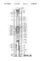
- FIG 2is a cross-sectional view of the releasable gun hanger of the present invention.
- FIG. 3is a cross-sectional view of a portion of the releasable gun hanger of the present invention.
- FIG. 4is a cross-sectional view of a portion of the releasable gun hanger of the present invention.
- FIG. 1a monobore completion system is shown where the well is completed using a tubing conveyed perforating completion system having an releasable gun hanger for the tubing conveyed perforating guns.
- a well casing 10 having a liner 12is shown in a well bore 14.
- the casing 10 and liner 12are typically cemented in the well bore 14.
- Installed on the upper end of the liner 12is a polished bore receptacle 16.
- the polished bore receptacle 16may be of any suitable type, such as sold by Otis Engineering Corporation, Dallas, Tx. Additionally, the polished bore receptacle may be either installed on the upper end of the liner 12 or the lower end of the casing 10.
- a tie-back seal assembly 18Engaging the polished bore of receptacle 16 is a tie-back seal assembly 18 having a plurality of seals 20 thereon, the tie-back seal assembly 18 being connected to the lower end of production pipe string 22
- the tie-back seal assembly 18may be of any suitable type such as sold by Otis Engineering Corporation, Dallas, Tx.
- FIG. 1a tubing conveyed perforating gun assembly 24 having a centralizer 26 thereon to centralize the perforating gun assembly 24 in the liner 12, a firing head 28 thereon, an on-off mandrel 30 on the upper end of the firing head 28, and a releasable gun hanger 32 connected to the lower end thereof.
- the on-off mandrel 30may be of any suitable type which is capable of mating with a suitable on-off shoe (not shown) attached to the end of either a drill pipe work string (not shown) or tubing string (not shown) which is used to run the perforating gun assembly 24 having releasable gun hanger 32 thereon into the liner 12 to the desired location.
- the perforating gun assembly 24is installed in the liner 12 and the drill pipe work string or tubing string is disconnected from the perforating gun assembly 24 and removed from the well.
- the firing head 28 on the perforating gun assembly 24may be of any suitable type, such as described in U.S. Pat. No. 4,614,156.
- the releasable gun hanger 32is shown in the liner 12.
- the releasable gun hanger 32comprises an automatic gun release section 34 and support section 36. As shown in FIG. 2, the releasable gun hanger 32 has the support section 36 in its locked running position for running through the liner 12.
- the automatic gun release section 34comprises a mandrel assembly 40, housing assembly 42 and explosive charge carrier assembly 44.
- the mandrel assembly 40comprises upper mandrel 46 and charge carrier mandrel 48.
- the upper mandrel 46comprises an elongated annular cylindrical member having, on the exterior thereof, first cylindrical surface 52, second cylindrical surface 54 and third cylindrical surface 56 and having, on the interior thereof, first bore 58, first threaded bore 60, second bore 62, frusto-conical bore 64, third bore 66, second threaded bore 68 and fourth bore 70.
- Charge carrier mandrel 48comprises an elongated annular cylindrical member having, on the exterior thereof, threaded surface 72 which threadedly engages second threaded bore 68 of upper mandrel 46, first cylindrical surface 74 having, in turn, a plurality of annular recesses 76 therein containing annular elastomeric seal means 78 therein which sealingly engage fourth bore 70 of upper mandrel 46, annular recess 80 therein, third cylindrical surface 84 and having, on the interior thereof, first bore 86, blind bore 88 and threaded recess 90 on the end thereof.
- the charge carrier mandrel 48further includes threaded aperture 92 having, in turn, set screw 94 therein and spacer sleeve 96, located on first cylindrical surface 74 of mandrel 48 and having, in turn, a plurality of apertures 98 therein.
- the charge carrier mandrel 48is threadedly connected at its lower end to the upper end of support mandrel 200.
- the housing assembly 42comprises upper housing 102 and lower housing 104.
- the upper housing 102comprises an elongated annular cylindrical member having, on the exterior thereof, frusto-conical surface 106 and cylindrical surface 108 and having, on the interior thereof, first bore 110 having, in turn, annular recess 112 therein containing annular elastomeric seal means 114 therein, which, in turn, slidingly, sealingly engage third cylindrical surface 56 of upper mandrel 46, second bore 116 and threaded bore 118.
- lower housing 104comprises an elongated annular cylindrical member having, on the exterior thereof, first cylindrical surface 120 having, in turn, annular recess 122 containing annular elastomeric seal means 124 therein which, in turn, sealingly engage a portion of second bore 116 of upper housing 102, first threaded surface 126 which threadedly engages threaded bore 118 of upper housing 102, second cylindrical surface 128 and second threaded surface 130 and having, on the interior thereof, first bore 132, frusto-conical surface 134, second bore 136, third bore 138 having, in turn, annular recess 140 containing annular elastomeric seal means 142 therein, and fourth bore 144.
- the explosive charge carrier assembly 44comprises booster holder 150, charge carrier 152, detonating cord 154 having booster 156 on one end thereof and end seal 158 on the other end thereof, and a plurality of shaped explosive charges 160.
- the booster holder 150which is retained within second bore 62 of upper mandrel 46 comprises an annular cylindrical member having a cylindrical exterior surface 162 having annular lugs 164 thereon and bore 166 therethrough through which detonating cord 154 extends.
- Charge carrier 152which is retained within first bore 86 of charge carrier mandrel 48 comprises an elongated annular cylindrical member having cylindrical exterior surface 168 having, in turn, fluid relief grooves 170 therein and having, on the interior thereof, threaded bore 172 threaded plug 174 therein having, in turn, bore 176 therein to receive the detonating cord 154 therethrough, bore 178 through which detonating cord 154 extends and a plurality of apertures 180 in which shaped explosive charges 160 are received.
- the charge carrier 152is retained within charge carrier mandrel 48 by set screw 94 engaging exterior surface 168 of the carrier 152.
- the annular cavity 182 between the mandrel assembly 40 and housing assembly 42is filled with suitable oil, such as silicon oil, to present substantial movement of the releasable gun hanger until actuated.
- suitable oilsuch as silicon oil
- the support section 36comprises support mandrel 200, slip wedge 202, and J-slot and slip assembly 204.
- the support mandrel 200comprises upper support mandrel 206 and slip mandrel 208.
- the upper support mandrel 206comprises an elongated cylindrical member having a upper threaded end 210 (see FIG. 3) which threadedly engages threaded recess 90 of charge carrier mandrel 48, cylindrical seal section 212 which slidingly sealingly engages annular elastomeric seal means 142 of lower housing 104 to seal the lower end of annular oil filled cavity 182, annular slip wedge abutment 214 and lower threaded end 216.
- the slip mandrel 208comprises an elongated annular cylindrical member having, on the exterior thereof, cylindrical surface 218, J-slot log 220, frusto-conical annular wedge 222, and threaded lower surface 224 and having, on the interior thereof, threaded bore 226 which threadedly engages lower threaded end 216 of upper support mandrel 206 and bore 228.
- the slip wedge 202comprises an annular cylindrical member having, on the exterior thereof, first cylindrical surface 230, first frusto-conical annular surface 232, second cylindrical surface 234, and second frusto-conical annular slip surface 236 and having, on the interior thereof, threaded bore 240 which threadedly engages second threaded surface 130 of lower housing 104 and bore 242 through which a portion of upper support mandrel 206 extends.
- the J-slot and slip assembly 204comprises a slip retainer housing 250 having, in turn, a plurality of cantilevered slips 252 resiliently mounted thereon by means of springs 254 which also bias the slips 252 against liner 12 and a conventional J-slot 256 in which the J-slot lug 220 on slip mandrel 208 moves to allow the setting of the releasable gun hanger 32 in the liner 12.
- the J-slot and slip housing 250includes a central bore 260 and frusto-conical annular abutment surface 262
- the J-slot and slip assembly 204 and slip mandrel 208can be of any conventional commercially available type, such as sold by Baker Hughes, Inc., Houston, Tx.
- the well boreis drilled and has a casing 10 and liner 12 typically cemented therein having either the liner 12 or casing 10 having, in turn, a polished bore receptacle 16 installed thereon.
- a production pipe string 22 having a seal assembly 18 on the end thereofis run into the casing 10 with the seal assembly 18 being installed in the polished bore receptacle 16 thereby preparing the well to be completed by perforating and to be immediately placed on production.
- the perforating gun 24 having a releasable gun hanger 32 connected theretois run into the liner 12 with the support section 36 being actuated to support the perforating gun 24 in the liner 12.
- the tubing stringis disconnected from the perforating gun 24 at the on-off connector 30 and pulled from the well.
- the wellhas the production pipe string 22 installed therein, is ready for production, and the perforating gun 24 supported in the liner 12 at the desired point so that the perforating gun 24 may be actuated to perforate the liner 12, the cement sheath surrounding the liner 12 and the surrounding formation to be produced through the liner 12 and production pipe string 22.
- the perforating gun 24 and releasable gun hanger 32may be installed in the liner 12 prior to the production pipe string 22 having seal assembly 18 on one end thereof is installed in polished bore receptacle 16. Also, the perforating gun 24 either may be located by any suitable method in the liner 12, or may comprise any number of perforating guns from one to eighty (80) or more.
- the releasable gun hanger 32is connected to the perforating gun bottom end tandem by threading upper mandrel 46 thereto. In this manner, the booster 156 connected to the end of the detonating cord 154 will be adjacent the booster in the tandem on the bottom of the perforating gun to be actuated thereby.
- the slip wedge 202is pushed downward into engagement with slips 252 to wedge the slips 252 into the liner 12 thereby allowing the weight of the tubing string, perforating gun 24 and releasable gun hanger 32 to be carried by the slips 252 and slip wedge 202.
- the tubing stringis disconnected from on-off connector 30 and removed from the well. At this time, the perforating gun 24 is ready to be actuated.
- a firing head 28is a pressure activated time delay type, such as described in U.S. Pat. No. 4,614,156, the fluid pressure in the casing 10 and liner 12 is increased to actuate the firing head 28, then bled off to either a pressure level equal to the hydrostatic fluid pressure of the formation to be perforated, or a pressure level less than the hydrostatic fluid pressure of the formation to be perforated, or a pressure level greater than the hydrostatic fluid pressure of the formation to be perforated.
- the firing head 28will cause detonation of the perforating charges in the perforating gun 24 and actuate the releasable gun hanger 32 to release the perforating gun 24 to drop to the bottom of the liner 12, the rat hole of the well.
- the booster 156 and detonating cord 154are actuated thereby causing shaped charges 160 to detonate rupturing charge carrier mandrel 48 in a plurality of locations.
- tubing having a mating on-off tool shoe thereonmay be run into the well to retrieve the perforating gun 24 and releasable gun hanger 32 from the well.
- the releasable gun hanger 32be installed on the bottom of the perforating gun 24, it could be installed on the top thereof with simple modifications.
- the present inventionoffers an improved completion technique and apparatus for wells. It will be further appreciated that the present invention offers changes, additions and modification which are within its scope, such as placing the releasable gun hanger on the top of the perforating gun, placing the polished bore receptacle on either the top of the liner or bottom of the casing, using other types of firing heads on the perforating gun, use of wireline to run the perforating gun and releasable gun hanger into the well, use of rupture discs instead of explosive charges to release the oil from the chamber to actuate the releasable gun hanger, etc.
Landscapes
- Geology (AREA)
- Life Sciences & Earth Sciences (AREA)
- Engineering & Computer Science (AREA)
- Mining & Mineral Resources (AREA)
- Environmental & Geological Engineering (AREA)
- Fluid Mechanics (AREA)
- Physics & Mathematics (AREA)
- General Life Sciences & Earth Sciences (AREA)
- Geochemistry & Mineralogy (AREA)
- Earth Drilling (AREA)
- Electrical Discharge Machining, Electrochemical Machining, And Combined Machining (AREA)
- Jib Cranes (AREA)
- Nozzles (AREA)
Abstract
Description
Claims (22)
Priority Applications (8)
| Application Number | Priority Date | Filing Date | Title |
|---|---|---|---|
| US07/695,478US5156213A (en) | 1991-05-03 | 1991-05-03 | Well completion method and apparatus |
| NO921677ANO303841B1 (en) | 1991-05-03 | 1992-04-29 | Device for releasing a perforating gun |
| DE69215006TDE69215006T2 (en) | 1991-05-03 | 1992-04-30 | Device for releasing a perforator |
| EP92303894AEP0517362B1 (en) | 1991-05-03 | 1992-04-30 | Perforating gun release apparatus |
| CA002067686ACA2067686A1 (en) | 1991-05-03 | 1992-04-30 | Well completion method and apparatus |
| DK92303894.7TDK0517362T3 (en) | 1991-05-03 | 1992-04-30 | Apparatus for releasing a perforating explosive capsule |
| AU15985/92AAU647709B2 (en) | 1991-05-03 | 1992-05-01 | Well completion method and apparatus |
| US07/930,122US5303772A (en) | 1991-05-03 | 1992-08-14 | Well completion apparatus |
Applications Claiming Priority (1)
| Application Number | Priority Date | Filing Date | Title |
|---|---|---|---|
| US07/695,478US5156213A (en) | 1991-05-03 | 1991-05-03 | Well completion method and apparatus |
Related Child Applications (1)
| Application Number | Title | Priority Date | Filing Date |
|---|---|---|---|
| US07/930,122ContinuationUS5303772A (en) | 1991-05-03 | 1992-08-14 | Well completion apparatus |
Publications (1)
| Publication Number | Publication Date |
|---|---|
| US5156213Atrue US5156213A (en) | 1992-10-20 |
Family
ID=24793154
Family Applications (2)
| Application Number | Title | Priority Date | Filing Date |
|---|---|---|---|
| US07/695,478Expired - LifetimeUS5156213A (en) | 1991-05-03 | 1991-05-03 | Well completion method and apparatus |
| US07/930,122Expired - LifetimeUS5303772A (en) | 1991-05-03 | 1992-08-14 | Well completion apparatus |
Family Applications After (1)
| Application Number | Title | Priority Date | Filing Date |
|---|---|---|---|
| US07/930,122Expired - LifetimeUS5303772A (en) | 1991-05-03 | 1992-08-14 | Well completion apparatus |
Country Status (7)
| Country | Link |
|---|---|
| US (2) | US5156213A (en) |
| EP (1) | EP0517362B1 (en) |
| AU (1) | AU647709B2 (en) |
| CA (1) | CA2067686A1 (en) |
| DE (1) | DE69215006T2 (en) |
| DK (1) | DK0517362T3 (en) |
| NO (1) | NO303841B1 (en) |
Cited By (117)
| Publication number | Priority date | Publication date | Assignee | Title |
|---|---|---|---|---|
| US5303772A (en)* | 1991-05-03 | 1994-04-19 | Halliburton Company | Well completion apparatus |
| WO1994015061A1 (en)* | 1992-12-18 | 1994-07-07 | Baker Hughes Incorporated | Apparatus and method of perforating wellbores |
| US5361843A (en)* | 1992-09-24 | 1994-11-08 | Halliburton Company | Dedicated perforatable nipple with integral isolation sleeve |
| US5366014A (en)* | 1993-11-04 | 1994-11-22 | Halliburton Company | Method and apparatus for perforating a well using a modular perforating gun system |
| US5398760A (en)* | 1993-10-08 | 1995-03-21 | Halliburton Company | Methods of perforating a well using coiled tubing |
| US5423382A (en)* | 1993-11-10 | 1995-06-13 | Dresser Industries, Inc. | Apparatus for releasing perforating gun equipment from a well casing |
| US5429192A (en)* | 1992-03-26 | 1995-07-04 | Schlumberger Technology Corporation | Method and apparatus for anchoring a perforating gun to a casing in a wellbore including a primary and a secondary anchor release mechanism |
| US5458196A (en)* | 1994-08-31 | 1995-10-17 | Halliburton Company | Through tubing gun hanger |
| US5669448A (en)* | 1995-12-08 | 1997-09-23 | Halliburton Energy Services, Inc. | Overbalance perforating and stimulation method for wells |
| US6173779B1 (en) | 1998-03-16 | 2001-01-16 | Halliburton Energy Services, Inc. | Collapsible well perforating apparatus |
| US6189621B1 (en)* | 1999-08-16 | 2001-02-20 | Smart Drilling And Completion, Inc. | Smart shuttles to complete oil and gas wells |
| US6591912B2 (en) | 2000-11-15 | 2003-07-15 | Baker Hughes Incorporated | Full bore automatic gun release module |
| US20040123983A1 (en)* | 1998-11-16 | 2004-07-01 | Enventure Global Technology L.L.C. | Isolation of subterranean zones |
| US20040251024A1 (en)* | 2003-06-10 | 2004-12-16 | Jones Ralph Harold | Single trip perforation/packing method |
| US6854533B2 (en) | 2002-12-20 | 2005-02-15 | Weatherford/Lamb, Inc. | Apparatus and method for drilling with casing |
| US6868906B1 (en) | 1994-10-14 | 2005-03-22 | Weatherford/Lamb, Inc. | Closed-loop conveyance systems for well servicing |
| US20050067163A1 (en)* | 2003-09-25 | 2005-03-31 | George Flint R. | Monobore release for tubing conveyed perforating |
| US6899186B2 (en) | 2002-12-13 | 2005-05-31 | Weatherford/Lamb, Inc. | Apparatus and method of drilling with casing |
| US20050257933A1 (en)* | 2004-05-20 | 2005-11-24 | Bernd-Georg Pietras | Casing running head |
| US6976541B2 (en) | 2000-09-18 | 2005-12-20 | Shell Oil Company | Liner hanger with sliding sleeve valve |
| US7011161B2 (en) | 1998-12-07 | 2006-03-14 | Shell Oil Company | Structural support |
| US7021390B2 (en) | 1998-12-07 | 2006-04-04 | Shell Oil Company | Tubular liner for wellbore casing |
| US7036610B1 (en) | 1994-10-14 | 2006-05-02 | Weatherford / Lamb, Inc. | Apparatus and method for completing oil and gas wells |
| US7040396B2 (en) | 1999-02-26 | 2006-05-09 | Shell Oil Company | Apparatus for releasably coupling two elements |
| US7044218B2 (en) | 1998-12-07 | 2006-05-16 | Shell Oil Company | Apparatus for radially expanding tubular members |
| US7048067B1 (en) | 1999-11-01 | 2006-05-23 | Shell Oil Company | Wellbore casing repair |
| US7055608B2 (en) | 1999-03-11 | 2006-06-06 | Shell Oil Company | Forming a wellbore casing while simultaneously drilling a wellbore |
| US7073598B2 (en) | 2001-05-17 | 2006-07-11 | Weatherford/Lamb, Inc. | Apparatus and methods for tubular makeup interlock |
| US7077211B2 (en) | 1998-12-07 | 2006-07-18 | Shell Oil Company | Method of creating a casing in a borehole |
| US7090021B2 (en) | 1998-08-24 | 2006-08-15 | Bernd-Georg Pietras | Apparatus for connecting tublars using a top drive |
| US7090023B2 (en) | 2002-10-11 | 2006-08-15 | Weatherford/Lamb, Inc. | Apparatus and methods for drilling with casing |
| US7093675B2 (en) | 2000-08-01 | 2006-08-22 | Weatherford/Lamb, Inc. | Drilling method |
| US7100710B2 (en) | 1994-10-14 | 2006-09-05 | Weatherford/Lamb, Inc. | Methods and apparatus for cementing drill strings in place for one pass drilling and completion of oil and gas wells |
| US7100684B2 (en) | 2000-07-28 | 2006-09-05 | Enventure Global Technology | Liner hanger with standoffs |
| US7100685B2 (en) | 2000-10-02 | 2006-09-05 | Enventure Global Technology | Mono-diameter wellbore casing |
| US7108084B2 (en) | 1994-10-14 | 2006-09-19 | Weatherford/Lamb, Inc. | Methods and apparatus for cementing drill strings in place for one pass drilling and completion of oil and gas wells |
| US7117957B2 (en) | 1998-12-22 | 2006-10-10 | Weatherford/Lamb, Inc. | Methods for drilling and lining a wellbore |
| US7128161B2 (en) | 1998-12-24 | 2006-10-31 | Weatherford/Lamb, Inc. | Apparatus and methods for facilitating the connection of tubulars using a top drive |
| US7128154B2 (en) | 2003-01-30 | 2006-10-31 | Weatherford/Lamb, Inc. | Single-direction cementing plug |
| US7131505B2 (en) | 2002-12-30 | 2006-11-07 | Weatherford/Lamb, Inc. | Drilling with concentric strings of casing |
| US7137454B2 (en) | 1998-07-22 | 2006-11-21 | Weatherford/Lamb, Inc. | Apparatus for facilitating the connection of tubulars using a top drive |
| US7140445B2 (en) | 1997-09-02 | 2006-11-28 | Weatherford/Lamb, Inc. | Method and apparatus for drilling with casing |
| US7147068B2 (en) | 1994-10-14 | 2006-12-12 | Weatherford / Lamb, Inc. | Methods and apparatus for cementing drill strings in place for one pass drilling and completion of oil and gas wells |
| US7147053B2 (en) | 1998-12-07 | 2006-12-12 | Shell Oil Company | Wellhead |
| US7168499B2 (en) | 1998-11-16 | 2007-01-30 | Shell Oil Company | Radial expansion of tubular members |
| US7168496B2 (en) | 2001-07-06 | 2007-01-30 | Eventure Global Technology | Liner hanger |
| US7172024B2 (en) | 2000-10-02 | 2007-02-06 | Shell Oil Company | Mono-diameter wellbore casing |
| US7185710B2 (en) | 1998-12-07 | 2007-03-06 | Enventure Global Technology | Mono-diameter wellbore casing |
| US7188687B2 (en) | 1998-12-22 | 2007-03-13 | Weatherford/Lamb, Inc. | Downhole filter |
| US7191840B2 (en) | 2003-03-05 | 2007-03-20 | Weatherford/Lamb, Inc. | Casing running and drilling system |
| US7195064B2 (en) | 1998-12-07 | 2007-03-27 | Enventure Global Technology | Mono-diameter wellbore casing |
| US20070079960A1 (en)* | 2000-03-02 | 2007-04-12 | Schlumberger Technology Corporation | Well Treatment System and Method |
| US7213656B2 (en) | 1998-12-24 | 2007-05-08 | Weatherford/Lamb, Inc. | Apparatus and method for facilitating the connection of tubulars using a top drive |
| US7216727B2 (en) | 1999-12-22 | 2007-05-15 | Weatherford/Lamb, Inc. | Drilling bit for drilling while running casing |
| US7219744B2 (en) | 1998-08-24 | 2007-05-22 | Weatherford/Lamb, Inc. | Method and apparatus for connecting tubulars using a top drive |
| US7225879B2 (en)* | 2001-11-14 | 2007-06-05 | Halliburton Energy Services, Inc. | Method and apparatus for a monodiameter wellbore, monodiameter casing, monobore, and/or monowell |
| US7228901B2 (en) | 1994-10-14 | 2007-06-12 | Weatherford/Lamb, Inc. | Method and apparatus for cementing drill strings in place for one pass drilling and completion of oil and gas wells |
| US7231985B2 (en) | 1998-11-16 | 2007-06-19 | Shell Oil Company | Radial expansion of tubular members |
| US7234542B2 (en) | 1994-10-14 | 2007-06-26 | Weatherford/Lamb, Inc. | Methods and apparatus for cementing drill strings in place for one pass drilling and completion of oil and gas wells |
| US7234531B2 (en) | 1999-12-03 | 2007-06-26 | Enventure Global Technology, Llc | Mono-diameter wellbore casing |
| US7240728B2 (en) | 1998-12-07 | 2007-07-10 | Shell Oil Company | Expandable tubulars with a radial passage and wall portions with different wall thicknesses |
| US7243731B2 (en) | 2001-08-20 | 2007-07-17 | Enventure Global Technology | Apparatus for radially expanding tubular members including a segmented expansion cone |
| US7258168B2 (en) | 2001-07-27 | 2007-08-21 | Enventure Global Technology L.L.C. | Liner hanger with slip joint sealing members and method of use |
| US7264067B2 (en) | 2003-10-03 | 2007-09-04 | Weatherford/Lamb, Inc. | Method of drilling and completing multiple wellbores inside a single caisson |
| US7290616B2 (en) | 2001-07-06 | 2007-11-06 | Enventure Global Technology, L.L.C. | Liner hanger |
| US7290605B2 (en) | 2001-12-27 | 2007-11-06 | Enventure Global Technology | Seal receptacle using expandable liner hanger |
| US7303022B2 (en) | 2002-10-11 | 2007-12-04 | Weatherford/Lamb, Inc. | Wired casing |
| US7308755B2 (en) | 2003-06-13 | 2007-12-18 | Shell Oil Company | Apparatus for forming a mono-diameter wellbore casing |
| US7311148B2 (en) | 1999-02-25 | 2007-12-25 | Weatherford/Lamb, Inc. | Methods and apparatus for wellbore construction and completion |
| US7325602B2 (en) | 2000-10-02 | 2008-02-05 | Shell Oil Company | Method and apparatus for forming a mono-diameter wellbore casing |
| US7325610B2 (en) | 2000-04-17 | 2008-02-05 | Weatherford/Lamb, Inc. | Methods and apparatus for handling and drilling with tubulars or casing |
| US7334650B2 (en) | 2000-04-13 | 2008-02-26 | Weatherford/Lamb, Inc. | Apparatus and methods for drilling a wellbore using casing |
| US7350563B2 (en) | 1999-07-09 | 2008-04-01 | Enventure Global Technology, L.L.C. | System for lining a wellbore casing |
| US7360591B2 (en) | 2002-05-29 | 2008-04-22 | Enventure Global Technology, Llc | System for radially expanding a tubular member |
| US7360594B2 (en) | 2003-03-05 | 2008-04-22 | Weatherford/Lamb, Inc. | Drilling with casing latch |
| US7363984B2 (en) | 1998-12-07 | 2008-04-29 | Enventure Global Technology, Llc | System for radially expanding a tubular member |
| US7370707B2 (en) | 2003-04-04 | 2008-05-13 | Weatherford/Lamb, Inc. | Method and apparatus for handling wellbore tubulars |
| US7377326B2 (en) | 2002-08-23 | 2008-05-27 | Enventure Global Technology, L.L.C. | Magnetic impulse applied sleeve method of forming a wellbore casing |
| US7398832B2 (en) | 2002-06-10 | 2008-07-15 | Enventure Global Technology, Llc | Mono-diameter wellbore casing |
| US7404444B2 (en) | 2002-09-20 | 2008-07-29 | Enventure Global Technology | Protective sleeve for expandable tubulars |
| US7410000B2 (en) | 2001-01-17 | 2008-08-12 | Enventure Global Technology, Llc. | Mono-diameter wellbore casing |
| US7413020B2 (en) | 2003-03-05 | 2008-08-19 | Weatherford/Lamb, Inc. | Full bore lined wellbores |
| US7416027B2 (en) | 2001-09-07 | 2008-08-26 | Enventure Global Technology, Llc | Adjustable expansion cone assembly |
| US7424918B2 (en) | 2002-08-23 | 2008-09-16 | Enventure Global Technology, L.L.C. | Interposed joint sealing layer method of forming a wellbore casing |
| US7438133B2 (en) | 2003-02-26 | 2008-10-21 | Enventure Global Technology, Llc | Apparatus and method for radially expanding and plastically deforming a tubular member |
| US7503397B2 (en) | 2004-07-30 | 2009-03-17 | Weatherford/Lamb, Inc. | Apparatus and methods of setting and retrieving casing with drilling latch and bottom hole assembly |
| US7503393B2 (en) | 2003-01-27 | 2009-03-17 | Enventure Global Technology, Inc. | Lubrication system for radially expanding tubular members |
| US7509722B2 (en) | 1997-09-02 | 2009-03-31 | Weatherford/Lamb, Inc. | Positioning and spinning device |
| US7513313B2 (en) | 2002-09-20 | 2009-04-07 | Enventure Global Technology, Llc | Bottom plug for forming a mono diameter wellbore casing |
| US7516790B2 (en) | 1999-12-03 | 2009-04-14 | Enventure Global Technology, Llc | Mono-diameter wellbore casing |
| US7552776B2 (en) | 1998-12-07 | 2009-06-30 | Enventure Global Technology, Llc | Anchor hangers |
| US7559365B2 (en) | 2001-11-12 | 2009-07-14 | Enventure Global Technology, Llc | Collapsible expansion cone |
| US7571774B2 (en) | 2002-09-20 | 2009-08-11 | Eventure Global Technology | Self-lubricating expansion mandrel for expandable tubular |
| US7603758B2 (en) | 1998-12-07 | 2009-10-20 | Shell Oil Company | Method of coupling a tubular member |
| US7617866B2 (en) | 1998-08-24 | 2009-11-17 | Weatherford/Lamb, Inc. | Methods and apparatus for connecting tubulars using a top drive |
| US7650944B1 (en) | 2003-07-11 | 2010-01-26 | Weatherford/Lamb, Inc. | Vessel for well intervention |
| US7712522B2 (en) | 2003-09-05 | 2010-05-11 | Enventure Global Technology, Llc | Expansion cone and system |
| US7712523B2 (en) | 2000-04-17 | 2010-05-11 | Weatherford/Lamb, Inc. | Top drive casing system |
| US7730965B2 (en) | 2002-12-13 | 2010-06-08 | Weatherford/Lamb, Inc. | Retractable joint and cementing shoe for use in completing a wellbore |
| US7739917B2 (en) | 2002-09-20 | 2010-06-22 | Enventure Global Technology, Llc | Pipe formability evaluation for expandable tubulars |
| US7740076B2 (en) | 2002-04-12 | 2010-06-22 | Enventure Global Technology, L.L.C. | Protective sleeve for threaded connections for expandable liner hanger |
| US7775290B2 (en) | 2003-04-17 | 2010-08-17 | Enventure Global Technology, Llc | Apparatus for radially expanding and plastically deforming a tubular member |
| US7793721B2 (en) | 2003-03-11 | 2010-09-14 | Eventure Global Technology, Llc | Apparatus for radially expanding and plastically deforming a tubular member |
| US7819185B2 (en) | 2004-08-13 | 2010-10-26 | Enventure Global Technology, Llc | Expandable tubular |
| US7857052B2 (en) | 2006-05-12 | 2010-12-28 | Weatherford/Lamb, Inc. | Stage cementing methods used in casing while drilling |
| US7886831B2 (en) | 2003-01-22 | 2011-02-15 | Enventure Global Technology, L.L.C. | Apparatus for radially expanding and plastically deforming a tubular member |
| US7918284B2 (en) | 2002-04-15 | 2011-04-05 | Enventure Global Technology, L.L.C. | Protective sleeve for threaded connections for expandable liner hanger |
| US7938201B2 (en) | 2002-12-13 | 2011-05-10 | Weatherford/Lamb, Inc. | Deep water drilling with casing |
| USRE42877E1 (en) | 2003-02-07 | 2011-11-01 | Weatherford/Lamb, Inc. | Methods and apparatus for wellbore construction and completion |
| US8276689B2 (en) | 2006-05-22 | 2012-10-02 | Weatherford/Lamb, Inc. | Methods and apparatus for drilling with casing |
| WO2013025985A3 (en)* | 2011-08-18 | 2013-04-25 | Baker Hughes Incorporated | Full flow gun system for monobore completions |
| US20170183927A1 (en)* | 2014-06-03 | 2017-06-29 | Halliburton Energy Services, Inc. | Multistage downhole anchor |
| US10689955B1 (en) | 2019-03-05 | 2020-06-23 | SWM International Inc. | Intelligent downhole perforating gun tube and components |
| US11078762B2 (en) | 2019-03-05 | 2021-08-03 | Swm International, Llc | Downhole perforating gun tube and components |
| US11268376B1 (en) | 2019-03-27 | 2022-03-08 | Acuity Technical Designs, LLC | Downhole safety switch and communication protocol |
| US11619119B1 (en) | 2020-04-10 | 2023-04-04 | Integrated Solutions, Inc. | Downhole gun tube extension |
| US12291945B1 (en) | 2019-03-05 | 2025-05-06 | Swm International, Llc | Downhole perforating gun system |
Families Citing this family (17)
| Publication number | Priority date | Publication date | Assignee | Title |
|---|---|---|---|---|
| US5960894A (en)* | 1998-03-13 | 1999-10-05 | Primex Technologies, Inc. | Expendable tubing conveyed perforator |
| US6206100B1 (en) | 1999-12-20 | 2001-03-27 | Osca, Inc. | Separable one-trip perforation and gravel pack system and method |
| US6568474B2 (en) | 1999-12-20 | 2003-05-27 | Bj Services, Usa | Rigless one-trip perforation and gravel pack system and method |
| US6422148B1 (en) | 2000-08-04 | 2002-07-23 | Schlumberger Technology Corporation | Impermeable and composite perforating gun assembly components |
| GB0023032D0 (en) | 2000-09-20 | 2000-11-01 | Weatherford Lamb | Downhole apparatus |
| US6550539B2 (en) | 2001-06-20 | 2003-04-22 | Weatherford/Lamb, Inc. | Tie back and method for use with expandable tubulars |
| US7610969B2 (en)* | 2006-05-26 | 2009-11-03 | Owen Oil Tools Lp | Perforating methods and devices for high wellbore pressure applications |
| US12241326B2 (en) | 2019-05-14 | 2025-03-04 | DynaEnergetics Europe GmbH | Single use setting tool for actuating a tool in a wellbore |
| US11255147B2 (en) | 2019-05-14 | 2022-02-22 | DynaEnergetics Europe GmbH | Single use setting tool for actuating a tool in a wellbore |
| US11578549B2 (en) | 2019-05-14 | 2023-02-14 | DynaEnergetics Europe GmbH | Single use setting tool for actuating a tool in a wellbore |
| US10927627B2 (en) | 2019-05-14 | 2021-02-23 | DynaEnergetics Europe GmbH | Single use setting tool for actuating a tool in a wellbore |
| US11204224B2 (en) | 2019-05-29 | 2021-12-21 | DynaEnergetics Europe GmbH | Reverse burn power charge for a wellbore tool |
| US12000267B2 (en) | 2021-09-24 | 2024-06-04 | DynaEnergetics Europe GmbH | Communication and location system for an autonomous frack system |
| US12312925B2 (en) | 2021-12-22 | 2025-05-27 | DynaEnergetics Europe GmbH | Manually oriented internal shaped charge alignment system and method of use |
| US12139984B2 (en) | 2022-04-15 | 2024-11-12 | Dbk Industries, Llc | Fixed-volume setting tool |
| WO2024013338A1 (en) | 2022-07-13 | 2024-01-18 | DynaEnergetics Europe GmbH | Gas driven wireline release tool |
| US11753889B1 (en) | 2022-07-13 | 2023-09-12 | DynaEnergetics Europe GmbH | Gas driven wireline release tool |
Citations (22)
| Publication number | Priority date | Publication date | Assignee | Title |
|---|---|---|---|---|
| US2706344A (en)* | 1953-03-11 | 1955-04-19 | Southern Wood Preserving Co | Method of controlled air seasoning of wood |
| US2749849A (en)* | 1952-06-25 | 1956-06-12 | Transit Res Corp | Street railway truck |
| US2799224A (en)* | 1954-01-25 | 1957-07-16 | Johnston Testers Inc | Apparatus for perforating casing |
| US2853944A (en)* | 1951-02-06 | 1958-09-30 | Borg Warner | Apparatus for perforating well casing and the like |
| US2873675A (en)* | 1953-06-17 | 1959-02-17 | Borg Warner | Method and apparatus for detonating explosive devices in bore holes |
| US2876843A (en)* | 1954-08-23 | 1959-03-10 | Jersey Prod Res Co | Gun perforator |
| US2906339A (en)* | 1954-03-30 | 1959-09-29 | Wilber H Griffin | Method and apparatus for completing wells |
| US2981185A (en)* | 1957-04-03 | 1961-04-25 | Jet Res Ct Inc | Well perforating apparatus |
| US3032109A (en)* | 1959-10-12 | 1962-05-01 | Jersey Prod Res Co | Gun perforating apparatus for wells |
| US3966236A (en)* | 1974-10-23 | 1976-06-29 | Vann Roy Randell | Releasable coupling |
| US4066282A (en)* | 1974-10-23 | 1978-01-03 | Vann Roy Randell | Positive tubing release coupling |
| US4078611A (en)* | 1975-10-14 | 1978-03-14 | Vann Roy Randell | High temperature perforating method |
| US4122899A (en)* | 1977-08-08 | 1978-10-31 | Brieger Emmet F | Well perforator with anchor and method |
| US4526233A (en)* | 1984-01-20 | 1985-07-02 | Baker Oil Tools, Inc. | Releasable coupling for tubing conveyed subterranean well perforating gun |
| US4557331A (en)* | 1983-11-14 | 1985-12-10 | Baker Oil Tools, Inc. | Well perforating method and apparatus |
| US4614156A (en)* | 1984-03-08 | 1986-09-30 | Halliburton Company | Pressure responsive explosion initiator with time delay and method of use |
| US4694878A (en)* | 1986-07-15 | 1987-09-22 | Hughes Tool Company | Disconnect sub for a tubing conveyed perforating gun |
| US4771827A (en)* | 1987-04-23 | 1988-09-20 | Halliburton Company | Automatic drop-off device for perforating guns |
| US4776393A (en)* | 1987-02-06 | 1988-10-11 | Dresser Industries, Inc. | Perforating gun automatic release mechanism |
| US4815540A (en)* | 1987-11-30 | 1989-03-28 | Baker Hughes Incorporated | Method and apparatus for releasing a well perforating gun from a supporting tubing string |
| US4905759A (en)* | 1988-03-25 | 1990-03-06 | Halliburton Company | Collapsible gun assembly |
| US5025861A (en)* | 1989-12-15 | 1991-06-25 | Schlumberger Technology Corporation | Tubing and wireline conveyed perforating method and apparatus |
Family Cites Families (8)
| Publication number | Priority date | Publication date | Assignee | Title |
|---|---|---|---|---|
| US2169559A (en)* | 1937-07-06 | 1939-08-15 | Halliburton Oil Well Cementing | Formation tester |
| US2192591A (en)* | 1938-09-13 | 1940-03-05 | Henry S Riehmond | Casing perforating gun |
| US3195646A (en)* | 1963-06-03 | 1965-07-20 | Brown Oil Tools | Multiple cone liner hanger |
| US3314478A (en)* | 1964-06-16 | 1967-04-18 | Burns Erwin | Method and apparatus for drilling oil wells |
| US3531236A (en)* | 1969-02-17 | 1970-09-29 | Texas Iron Works | Methods and apparatus for completing oil and gas wells |
| US4317485A (en)* | 1980-05-23 | 1982-03-02 | Baker International Corporation | Pump catcher apparatus |
| US4756363A (en)* | 1987-01-15 | 1988-07-12 | Nl Industries, Inc. | Apparatus for releasing a perforation gun |
| US5156213A (en)* | 1991-05-03 | 1992-10-20 | Halliburton Company | Well completion method and apparatus |
- 1991
- 1991-05-03USUS07/695,478patent/US5156213A/ennot_activeExpired - Lifetime
- 1992
- 1992-04-29NONO921677Apatent/NO303841B1/ennot_activeIP Right Cessation
- 1992-04-30EPEP92303894Apatent/EP0517362B1/ennot_activeExpired - Lifetime
- 1992-04-30CACA002067686Apatent/CA2067686A1/ennot_activeAbandoned
- 1992-04-30DEDE69215006Tpatent/DE69215006T2/ennot_activeExpired - Fee Related
- 1992-04-30DKDK92303894.7Tpatent/DK0517362T3/enactive
- 1992-05-01AUAU15985/92Apatent/AU647709B2/ennot_activeExpired
- 1992-08-14USUS07/930,122patent/US5303772A/ennot_activeExpired - Lifetime
Patent Citations (22)
| Publication number | Priority date | Publication date | Assignee | Title |
|---|---|---|---|---|
| US2853944A (en)* | 1951-02-06 | 1958-09-30 | Borg Warner | Apparatus for perforating well casing and the like |
| US2749849A (en)* | 1952-06-25 | 1956-06-12 | Transit Res Corp | Street railway truck |
| US2706344A (en)* | 1953-03-11 | 1955-04-19 | Southern Wood Preserving Co | Method of controlled air seasoning of wood |
| US2873675A (en)* | 1953-06-17 | 1959-02-17 | Borg Warner | Method and apparatus for detonating explosive devices in bore holes |
| US2799224A (en)* | 1954-01-25 | 1957-07-16 | Johnston Testers Inc | Apparatus for perforating casing |
| US2906339A (en)* | 1954-03-30 | 1959-09-29 | Wilber H Griffin | Method and apparatus for completing wells |
| US2876843A (en)* | 1954-08-23 | 1959-03-10 | Jersey Prod Res Co | Gun perforator |
| US2981185A (en)* | 1957-04-03 | 1961-04-25 | Jet Res Ct Inc | Well perforating apparatus |
| US3032109A (en)* | 1959-10-12 | 1962-05-01 | Jersey Prod Res Co | Gun perforating apparatus for wells |
| US4066282A (en)* | 1974-10-23 | 1978-01-03 | Vann Roy Randell | Positive tubing release coupling |
| US3966236A (en)* | 1974-10-23 | 1976-06-29 | Vann Roy Randell | Releasable coupling |
| US4078611A (en)* | 1975-10-14 | 1978-03-14 | Vann Roy Randell | High temperature perforating method |
| US4122899A (en)* | 1977-08-08 | 1978-10-31 | Brieger Emmet F | Well perforator with anchor and method |
| US4557331A (en)* | 1983-11-14 | 1985-12-10 | Baker Oil Tools, Inc. | Well perforating method and apparatus |
| US4526233A (en)* | 1984-01-20 | 1985-07-02 | Baker Oil Tools, Inc. | Releasable coupling for tubing conveyed subterranean well perforating gun |
| US4614156A (en)* | 1984-03-08 | 1986-09-30 | Halliburton Company | Pressure responsive explosion initiator with time delay and method of use |
| US4694878A (en)* | 1986-07-15 | 1987-09-22 | Hughes Tool Company | Disconnect sub for a tubing conveyed perforating gun |
| US4776393A (en)* | 1987-02-06 | 1988-10-11 | Dresser Industries, Inc. | Perforating gun automatic release mechanism |
| US4771827A (en)* | 1987-04-23 | 1988-09-20 | Halliburton Company | Automatic drop-off device for perforating guns |
| US4815540A (en)* | 1987-11-30 | 1989-03-28 | Baker Hughes Incorporated | Method and apparatus for releasing a well perforating gun from a supporting tubing string |
| US4905759A (en)* | 1988-03-25 | 1990-03-06 | Halliburton Company | Collapsible gun assembly |
| US5025861A (en)* | 1989-12-15 | 1991-06-25 | Schlumberger Technology Corporation | Tubing and wireline conveyed perforating method and apparatus |
Cited By (172)
| Publication number | Priority date | Publication date | Assignee | Title |
|---|---|---|---|---|
| US5303772A (en)* | 1991-05-03 | 1994-04-19 | Halliburton Company | Well completion apparatus |
| US5429192A (en)* | 1992-03-26 | 1995-07-04 | Schlumberger Technology Corporation | Method and apparatus for anchoring a perforating gun to a casing in a wellbore including a primary and a secondary anchor release mechanism |
| US5361843A (en)* | 1992-09-24 | 1994-11-08 | Halliburton Company | Dedicated perforatable nipple with integral isolation sleeve |
| US5390742A (en)* | 1992-09-24 | 1995-02-21 | Halliburton Company | Internally sealable perforable nipple for downhole well applications |
| WO1994015061A1 (en)* | 1992-12-18 | 1994-07-07 | Baker Hughes Incorporated | Apparatus and method of perforating wellbores |
| US5370186A (en)* | 1992-12-18 | 1994-12-06 | Baker Hughes Incorporated | Apparatus and method of perforating wellbores |
| US5398760A (en)* | 1993-10-08 | 1995-03-21 | Halliburton Company | Methods of perforating a well using coiled tubing |
| EP0647765A3 (en)* | 1993-10-08 | 1997-09-03 | Halliburton Co | Method of perforating a well using coiled tubing. |
| EP0652351A1 (en)* | 1993-11-04 | 1995-05-10 | Halliburton Company | Method of perforating a well |
| US5366014A (en)* | 1993-11-04 | 1994-11-22 | Halliburton Company | Method and apparatus for perforating a well using a modular perforating gun system |
| US5423382A (en)* | 1993-11-10 | 1995-06-13 | Dresser Industries, Inc. | Apparatus for releasing perforating gun equipment from a well casing |
| EP0882869A3 (en)* | 1994-08-31 | 1999-03-10 | Halliburton Energy Services, Inc. | Method of perforating a well casing and downhole tool hanger |
| US5458196A (en)* | 1994-08-31 | 1995-10-17 | Halliburton Company | Through tubing gun hanger |
| AU694790B2 (en)* | 1994-08-31 | 1998-07-30 | Halliburton Company | Through tubing gun hanger |
| US7165634B2 (en) | 1994-10-14 | 2007-01-23 | Weatherford/Lamb, Inc. | Method and apparatus for cementing drill strings in place for one pass drilling and completion of oil and gas wells |
| US7234542B2 (en) | 1994-10-14 | 2007-06-26 | Weatherford/Lamb, Inc. | Methods and apparatus for cementing drill strings in place for one pass drilling and completion of oil and gas wells |
| US7100710B2 (en) | 1994-10-14 | 2006-09-05 | Weatherford/Lamb, Inc. | Methods and apparatus for cementing drill strings in place for one pass drilling and completion of oil and gas wells |
| US7048050B2 (en) | 1994-10-14 | 2006-05-23 | Weatherford/Lamb, Inc. | Method and apparatus for cementing drill strings in place for one pass drilling and completion of oil and gas wells |
| US7108084B2 (en) | 1994-10-14 | 2006-09-19 | Weatherford/Lamb, Inc. | Methods and apparatus for cementing drill strings in place for one pass drilling and completion of oil and gas wells |
| US7147068B2 (en) | 1994-10-14 | 2006-12-12 | Weatherford / Lamb, Inc. | Methods and apparatus for cementing drill strings in place for one pass drilling and completion of oil and gas wells |
| US7036610B1 (en) | 1994-10-14 | 2006-05-02 | Weatherford / Lamb, Inc. | Apparatus and method for completing oil and gas wells |
| US7228901B2 (en) | 1994-10-14 | 2007-06-12 | Weatherford/Lamb, Inc. | Method and apparatus for cementing drill strings in place for one pass drilling and completion of oil and gas wells |
| US6868906B1 (en) | 1994-10-14 | 2005-03-22 | Weatherford/Lamb, Inc. | Closed-loop conveyance systems for well servicing |
| US5669448A (en)* | 1995-12-08 | 1997-09-23 | Halliburton Energy Services, Inc. | Overbalance perforating and stimulation method for wells |
| US7140445B2 (en) | 1997-09-02 | 2006-11-28 | Weatherford/Lamb, Inc. | Method and apparatus for drilling with casing |
| US7509722B2 (en) | 1997-09-02 | 2009-03-31 | Weatherford/Lamb, Inc. | Positioning and spinning device |
| US6173779B1 (en) | 1998-03-16 | 2001-01-16 | Halliburton Energy Services, Inc. | Collapsible well perforating apparatus |
| US7137454B2 (en) | 1998-07-22 | 2006-11-21 | Weatherford/Lamb, Inc. | Apparatus for facilitating the connection of tubulars using a top drive |
| US7219744B2 (en) | 1998-08-24 | 2007-05-22 | Weatherford/Lamb, Inc. | Method and apparatus for connecting tubulars using a top drive |
| US7617866B2 (en) | 1998-08-24 | 2009-11-17 | Weatherford/Lamb, Inc. | Methods and apparatus for connecting tubulars using a top drive |
| US7090021B2 (en) | 1998-08-24 | 2006-08-15 | Bernd-Georg Pietras | Apparatus for connecting tublars using a top drive |
| US7168499B2 (en) | 1998-11-16 | 2007-01-30 | Shell Oil Company | Radial expansion of tubular members |
| US7275601B2 (en) | 1998-11-16 | 2007-10-02 | Shell Oil Company | Radial expansion of tubular members |
| US20040123983A1 (en)* | 1998-11-16 | 2004-07-01 | Enventure Global Technology L.L.C. | Isolation of subterranean zones |
| US7299881B2 (en) | 1998-11-16 | 2007-11-27 | Shell Oil Company | Radial expansion of tubular members |
| US7246667B2 (en) | 1998-11-16 | 2007-07-24 | Shell Oil Company | Radial expansion of tubular members |
| US7270188B2 (en) | 1998-11-16 | 2007-09-18 | Shell Oil Company | Radial expansion of tubular members |
| US7121352B2 (en) | 1998-11-16 | 2006-10-17 | Enventure Global Technology | Isolation of subterranean zones |
| US7357190B2 (en) | 1998-11-16 | 2008-04-15 | Shell Oil Company | Radial expansion of tubular members |
| US7231985B2 (en) | 1998-11-16 | 2007-06-19 | Shell Oil Company | Radial expansion of tubular members |
| US7086475B2 (en) | 1998-12-07 | 2006-08-08 | Shell Oil Company | Method of inserting a tubular member into a wellbore |
| US7147053B2 (en) | 1998-12-07 | 2006-12-12 | Shell Oil Company | Wellhead |
| US7077213B2 (en) | 1998-12-07 | 2006-07-18 | Shell Oil Company | Expansion cone for radially expanding tubular members |
| US7665532B2 (en) | 1998-12-07 | 2010-02-23 | Shell Oil Company | Pipeline |
| US7603758B2 (en) | 1998-12-07 | 2009-10-20 | Shell Oil Company | Method of coupling a tubular member |
| US7077211B2 (en) | 1998-12-07 | 2006-07-18 | Shell Oil Company | Method of creating a casing in a borehole |
| US7552776B2 (en) | 1998-12-07 | 2009-06-30 | Enventure Global Technology, Llc | Anchor hangers |
| US7434618B2 (en) | 1998-12-07 | 2008-10-14 | Shell Oil Company | Apparatus for expanding a tubular member |
| US7048062B2 (en) | 1998-12-07 | 2006-05-23 | Shell Oil Company | Method of selecting tubular members |
| US7419009B2 (en) | 1998-12-07 | 2008-09-02 | Shell Oil Company | Apparatus for radially expanding and plastically deforming a tubular member |
| US7363984B2 (en) | 1998-12-07 | 2008-04-29 | Enventure Global Technology, Llc | System for radially expanding a tubular member |
| US7357188B1 (en) | 1998-12-07 | 2008-04-15 | Shell Oil Company | Mono-diameter wellbore casing |
| US7174964B2 (en) | 1998-12-07 | 2007-02-13 | Shell Oil Company | Wellhead with radially expanded tubulars |
| US7121337B2 (en) | 1998-12-07 | 2006-10-17 | Shell Oil Company | Apparatus for expanding a tubular member |
| US7044218B2 (en) | 1998-12-07 | 2006-05-16 | Shell Oil Company | Apparatus for radially expanding tubular members |
| US7195064B2 (en) | 1998-12-07 | 2007-03-27 | Enventure Global Technology | Mono-diameter wellbore casing |
| US7350564B2 (en) | 1998-12-07 | 2008-04-01 | Enventure Global Technology, L.L.C. | Mono-diameter wellbore casing |
| US7195061B2 (en) | 1998-12-07 | 2007-03-27 | Shell Oil Company | Apparatus for expanding a tubular member |
| US7240729B2 (en) | 1998-12-07 | 2007-07-10 | Shell Oil Company | Apparatus for expanding a tubular member |
| US7240728B2 (en) | 1998-12-07 | 2007-07-10 | Shell Oil Company | Expandable tubulars with a radial passage and wall portions with different wall thicknesses |
| US7036582B2 (en) | 1998-12-07 | 2006-05-02 | Shell Oil Company | Expansion cone for radially expanding tubular members |
| US7216701B2 (en) | 1998-12-07 | 2007-05-15 | Shell Oil Company | Apparatus for expanding a tubular member |
| US7185710B2 (en) | 1998-12-07 | 2007-03-06 | Enventure Global Technology | Mono-diameter wellbore casing |
| US7159665B2 (en) | 1998-12-07 | 2007-01-09 | Shell Oil Company | Wellbore casing |
| US7021390B2 (en) | 1998-12-07 | 2006-04-04 | Shell Oil Company | Tubular liner for wellbore casing |
| US7198100B2 (en) | 1998-12-07 | 2007-04-03 | Shell Oil Company | Apparatus for expanding a tubular member |
| US7011161B2 (en) | 1998-12-07 | 2006-03-14 | Shell Oil Company | Structural support |
| US7188687B2 (en) | 1998-12-22 | 2007-03-13 | Weatherford/Lamb, Inc. | Downhole filter |
| US7117957B2 (en) | 1998-12-22 | 2006-10-10 | Weatherford/Lamb, Inc. | Methods for drilling and lining a wellbore |
| US7213656B2 (en) | 1998-12-24 | 2007-05-08 | Weatherford/Lamb, Inc. | Apparatus and method for facilitating the connection of tubulars using a top drive |
| US7128161B2 (en) | 1998-12-24 | 2006-10-31 | Weatherford/Lamb, Inc. | Apparatus and methods for facilitating the connection of tubulars using a top drive |
| US7311148B2 (en) | 1999-02-25 | 2007-12-25 | Weatherford/Lamb, Inc. | Methods and apparatus for wellbore construction and completion |
| US7556092B2 (en) | 1999-02-26 | 2009-07-07 | Enventure Global Technology, Llc | Flow control system for an apparatus for radially expanding tubular members |
| US7044221B2 (en)* | 1999-02-26 | 2006-05-16 | Shell Oil Company | Apparatus for coupling a tubular member to a preexisting structure |
| US7040396B2 (en) | 1999-02-26 | 2006-05-09 | Shell Oil Company | Apparatus for releasably coupling two elements |
| US7438132B2 (en) | 1999-03-11 | 2008-10-21 | Shell Oil Company | Concentric pipes expanded at the pipe ends and method of forming |
| US7055608B2 (en) | 1999-03-11 | 2006-06-06 | Shell Oil Company | Forming a wellbore casing while simultaneously drilling a wellbore |
| US7350563B2 (en) | 1999-07-09 | 2008-04-01 | Enventure Global Technology, L.L.C. | System for lining a wellbore casing |
| WO2001012946A1 (en)* | 1999-08-16 | 2001-02-22 | Smart Drilling And Completion, Inc. | Smart shuttles to complete oil and gas wells |
| US6189621B1 (en)* | 1999-08-16 | 2001-02-20 | Smart Drilling And Completion, Inc. | Smart shuttles to complete oil and gas wells |
| US7048067B1 (en) | 1999-11-01 | 2006-05-23 | Shell Oil Company | Wellbore casing repair |
| US7234531B2 (en) | 1999-12-03 | 2007-06-26 | Enventure Global Technology, Llc | Mono-diameter wellbore casing |
| US7516790B2 (en) | 1999-12-03 | 2009-04-14 | Enventure Global Technology, Llc | Mono-diameter wellbore casing |
| US7216727B2 (en) | 1999-12-22 | 2007-05-15 | Weatherford/Lamb, Inc. | Drilling bit for drilling while running casing |
| US20070079960A1 (en)* | 2000-03-02 | 2007-04-12 | Schlumberger Technology Corporation | Well Treatment System and Method |
| US7428921B2 (en)* | 2000-03-02 | 2008-09-30 | Schlumberger Technology Corporation | Well treatment system and method |
| US7334650B2 (en) | 2000-04-13 | 2008-02-26 | Weatherford/Lamb, Inc. | Apparatus and methods for drilling a wellbore using casing |
| US7325610B2 (en) | 2000-04-17 | 2008-02-05 | Weatherford/Lamb, Inc. | Methods and apparatus for handling and drilling with tubulars or casing |
| US7712523B2 (en) | 2000-04-17 | 2010-05-11 | Weatherford/Lamb, Inc. | Top drive casing system |
| US7100684B2 (en) | 2000-07-28 | 2006-09-05 | Enventure Global Technology | Liner hanger with standoffs |
| US7093675B2 (en) | 2000-08-01 | 2006-08-22 | Weatherford/Lamb, Inc. | Drilling method |
| US6976541B2 (en) | 2000-09-18 | 2005-12-20 | Shell Oil Company | Liner hanger with sliding sleeve valve |
| US7172021B2 (en) | 2000-09-18 | 2007-02-06 | Shell Oil Company | Liner hanger with sliding sleeve valve |
| US7172024B2 (en) | 2000-10-02 | 2007-02-06 | Shell Oil Company | Mono-diameter wellbore casing |
| US7172019B2 (en) | 2000-10-02 | 2007-02-06 | Shell Oil Company | Method and apparatus for forming a mono-diameter wellbore casing |
| US7204007B2 (en) | 2000-10-02 | 2007-04-17 | Shell Oil Company | Method and apparatus for forming a mono-diameter wellbore casing |
| US7363691B2 (en) | 2000-10-02 | 2008-04-29 | Shell Oil Company | Method and apparatus for forming a mono-diameter wellbore casing |
| US7325602B2 (en) | 2000-10-02 | 2008-02-05 | Shell Oil Company | Method and apparatus for forming a mono-diameter wellbore casing |
| US7363690B2 (en) | 2000-10-02 | 2008-04-29 | Shell Oil Company | Method and apparatus for forming a mono-diameter wellbore casing |
| US7100685B2 (en) | 2000-10-02 | 2006-09-05 | Enventure Global Technology | Mono-diameter wellbore casing |
| US7146702B2 (en) | 2000-10-02 | 2006-12-12 | Shell Oil Company | Method and apparatus for forming a mono-diameter wellbore casing |
| US7201223B2 (en) | 2000-10-02 | 2007-04-10 | Shell Oil Company | Method and apparatus for forming a mono-diameter wellbore casing |
| US20030192696A1 (en)* | 2000-11-15 | 2003-10-16 | Baker Hughes Incorporated | Full bore automatic gun release module |
| US6591912B2 (en) | 2000-11-15 | 2003-07-15 | Baker Hughes Incorporated | Full bore automatic gun release module |
| US6880637B2 (en) | 2000-11-15 | 2005-04-19 | Baker Hughes Incorporated | Full bore automatic gun release module |
| US7410000B2 (en) | 2001-01-17 | 2008-08-12 | Enventure Global Technology, Llc. | Mono-diameter wellbore casing |
| US7073598B2 (en) | 2001-05-17 | 2006-07-11 | Weatherford/Lamb, Inc. | Apparatus and methods for tubular makeup interlock |
| US7290616B2 (en) | 2001-07-06 | 2007-11-06 | Enventure Global Technology, L.L.C. | Liner hanger |
| US7168496B2 (en) | 2001-07-06 | 2007-01-30 | Eventure Global Technology | Liner hanger |
| US7258168B2 (en) | 2001-07-27 | 2007-08-21 | Enventure Global Technology L.L.C. | Liner hanger with slip joint sealing members and method of use |
| US7243731B2 (en) | 2001-08-20 | 2007-07-17 | Enventure Global Technology | Apparatus for radially expanding tubular members including a segmented expansion cone |
| US7416027B2 (en) | 2001-09-07 | 2008-08-26 | Enventure Global Technology, Llc | Adjustable expansion cone assembly |
| US7559365B2 (en) | 2001-11-12 | 2009-07-14 | Enventure Global Technology, Llc | Collapsible expansion cone |
| US7341117B2 (en) | 2001-11-14 | 2008-03-11 | Halliburton Energy Services, Inc. | Method and apparatus for a monodiameter wellbore, monodiameter casing, monobore, and/or monowell |
| US7571777B2 (en) | 2001-11-14 | 2009-08-11 | Halliburton Energy Services, Inc. | Method and apparatus for a monodiameter wellbore, monodiameter casing, monobore, and/or monowell |
| AU2009201056B2 (en)* | 2001-11-14 | 2011-06-02 | Halliburton Energy Services, Inc. | Method and apparatus for a monodiameter wellbore, monodiameter casing, monobore, and/or monowell |
| US7225879B2 (en)* | 2001-11-14 | 2007-06-05 | Halliburton Energy Services, Inc. | Method and apparatus for a monodiameter wellbore, monodiameter casing, monobore, and/or monowell |
| US7290605B2 (en) | 2001-12-27 | 2007-11-06 | Enventure Global Technology | Seal receptacle using expandable liner hanger |
| US7740076B2 (en) | 2002-04-12 | 2010-06-22 | Enventure Global Technology, L.L.C. | Protective sleeve for threaded connections for expandable liner hanger |
| US7918284B2 (en) | 2002-04-15 | 2011-04-05 | Enventure Global Technology, L.L.C. | Protective sleeve for threaded connections for expandable liner hanger |
| US7360591B2 (en) | 2002-05-29 | 2008-04-22 | Enventure Global Technology, Llc | System for radially expanding a tubular member |
| US7398832B2 (en) | 2002-06-10 | 2008-07-15 | Enventure Global Technology, Llc | Mono-diameter wellbore casing |
| US7377326B2 (en) | 2002-08-23 | 2008-05-27 | Enventure Global Technology, L.L.C. | Magnetic impulse applied sleeve method of forming a wellbore casing |
| US7424918B2 (en) | 2002-08-23 | 2008-09-16 | Enventure Global Technology, L.L.C. | Interposed joint sealing layer method of forming a wellbore casing |
| US7404444B2 (en) | 2002-09-20 | 2008-07-29 | Enventure Global Technology | Protective sleeve for expandable tubulars |
| US7513313B2 (en) | 2002-09-20 | 2009-04-07 | Enventure Global Technology, Llc | Bottom plug for forming a mono diameter wellbore casing |
| US7571774B2 (en) | 2002-09-20 | 2009-08-11 | Eventure Global Technology | Self-lubricating expansion mandrel for expandable tubular |
| US7739917B2 (en) | 2002-09-20 | 2010-06-22 | Enventure Global Technology, Llc | Pipe formability evaluation for expandable tubulars |
| US7090023B2 (en) | 2002-10-11 | 2006-08-15 | Weatherford/Lamb, Inc. | Apparatus and methods for drilling with casing |
| US7303022B2 (en) | 2002-10-11 | 2007-12-04 | Weatherford/Lamb, Inc. | Wired casing |
| US7083005B2 (en) | 2002-12-13 | 2006-08-01 | Weatherford/Lamb, Inc. | Apparatus and method of drilling with casing |
| US7730965B2 (en) | 2002-12-13 | 2010-06-08 | Weatherford/Lamb, Inc. | Retractable joint and cementing shoe for use in completing a wellbore |
| US6899186B2 (en) | 2002-12-13 | 2005-05-31 | Weatherford/Lamb, Inc. | Apparatus and method of drilling with casing |
| US7938201B2 (en) | 2002-12-13 | 2011-05-10 | Weatherford/Lamb, Inc. | Deep water drilling with casing |
| US6854533B2 (en) | 2002-12-20 | 2005-02-15 | Weatherford/Lamb, Inc. | Apparatus and method for drilling with casing |
| US7131505B2 (en) | 2002-12-30 | 2006-11-07 | Weatherford/Lamb, Inc. | Drilling with concentric strings of casing |
| US7886831B2 (en) | 2003-01-22 | 2011-02-15 | Enventure Global Technology, L.L.C. | Apparatus for radially expanding and plastically deforming a tubular member |
| US7503393B2 (en) | 2003-01-27 | 2009-03-17 | Enventure Global Technology, Inc. | Lubrication system for radially expanding tubular members |
| US7128154B2 (en) | 2003-01-30 | 2006-10-31 | Weatherford/Lamb, Inc. | Single-direction cementing plug |
| USRE42877E1 (en) | 2003-02-07 | 2011-11-01 | Weatherford/Lamb, Inc. | Methods and apparatus for wellbore construction and completion |
| US7438133B2 (en) | 2003-02-26 | 2008-10-21 | Enventure Global Technology, Llc | Apparatus and method for radially expanding and plastically deforming a tubular member |
| US7191840B2 (en) | 2003-03-05 | 2007-03-20 | Weatherford/Lamb, Inc. | Casing running and drilling system |
| US7360594B2 (en) | 2003-03-05 | 2008-04-22 | Weatherford/Lamb, Inc. | Drilling with casing latch |
| US7413020B2 (en) | 2003-03-05 | 2008-08-19 | Weatherford/Lamb, Inc. | Full bore lined wellbores |
| US7793721B2 (en) | 2003-03-11 | 2010-09-14 | Eventure Global Technology, Llc | Apparatus for radially expanding and plastically deforming a tubular member |
| US7370707B2 (en) | 2003-04-04 | 2008-05-13 | Weatherford/Lamb, Inc. | Method and apparatus for handling wellbore tubulars |
| US7775290B2 (en) | 2003-04-17 | 2010-08-17 | Enventure Global Technology, Llc | Apparatus for radially expanding and plastically deforming a tubular member |
| US20040251024A1 (en)* | 2003-06-10 | 2004-12-16 | Jones Ralph Harold | Single trip perforation/packing method |
| US7165611B2 (en) | 2003-06-10 | 2007-01-23 | Halliburton Energy Services, Inc. | Single trip perforation/packing method |
| US7308755B2 (en) | 2003-06-13 | 2007-12-18 | Shell Oil Company | Apparatus for forming a mono-diameter wellbore casing |
| US7650944B1 (en) | 2003-07-11 | 2010-01-26 | Weatherford/Lamb, Inc. | Vessel for well intervention |
| US7712522B2 (en) | 2003-09-05 | 2010-05-11 | Enventure Global Technology, Llc | Expansion cone and system |
| US20050067163A1 (en)* | 2003-09-25 | 2005-03-31 | George Flint R. | Monobore release for tubing conveyed perforating |
| US7264067B2 (en) | 2003-10-03 | 2007-09-04 | Weatherford/Lamb, Inc. | Method of drilling and completing multiple wellbores inside a single caisson |
| US20050257933A1 (en)* | 2004-05-20 | 2005-11-24 | Bernd-Georg Pietras | Casing running head |
| US7284617B2 (en) | 2004-05-20 | 2007-10-23 | Weatherford/Lamb, Inc. | Casing running head |
| US7503397B2 (en) | 2004-07-30 | 2009-03-17 | Weatherford/Lamb, Inc. | Apparatus and methods of setting and retrieving casing with drilling latch and bottom hole assembly |
| US7819185B2 (en) | 2004-08-13 | 2010-10-26 | Enventure Global Technology, Llc | Expandable tubular |
| US7857052B2 (en) | 2006-05-12 | 2010-12-28 | Weatherford/Lamb, Inc. | Stage cementing methods used in casing while drilling |
| US8276689B2 (en) | 2006-05-22 | 2012-10-02 | Weatherford/Lamb, Inc. | Methods and apparatus for drilling with casing |
| WO2013025985A3 (en)* | 2011-08-18 | 2013-04-25 | Baker Hughes Incorporated | Full flow gun system for monobore completions |
| US20170183927A1 (en)* | 2014-06-03 | 2017-06-29 | Halliburton Energy Services, Inc. | Multistage downhole anchor |
| US10689955B1 (en) | 2019-03-05 | 2020-06-23 | SWM International Inc. | Intelligent downhole perforating gun tube and components |
| US11078762B2 (en) | 2019-03-05 | 2021-08-03 | Swm International, Llc | Downhole perforating gun tube and components |
| US11624266B2 (en) | 2019-03-05 | 2023-04-11 | Swm International, Llc | Downhole perforating gun tube and components |
| US11976539B2 (en) | 2019-03-05 | 2024-05-07 | Swm International, Llc | Downhole perforating gun tube and components |
| US12221864B1 (en) | 2019-03-05 | 2025-02-11 | Swm International, Llc | Downhole perforating gun tube and components |
| US12291945B1 (en) | 2019-03-05 | 2025-05-06 | Swm International, Llc | Downhole perforating gun system |
| US12398627B1 (en) | 2019-03-05 | 2025-08-26 | Swm International, Llc | Downhole perforating gun tube and components |
| US11268376B1 (en) | 2019-03-27 | 2022-03-08 | Acuity Technical Designs, LLC | Downhole safety switch and communication protocol |
| US11686195B2 (en) | 2019-03-27 | 2023-06-27 | Acuity Technical Designs, LLC | Downhole switch and communication protocol |
| US11619119B1 (en) | 2020-04-10 | 2023-04-04 | Integrated Solutions, Inc. | Downhole gun tube extension |
Also Published As
| Publication number | Publication date |
|---|---|
| NO921677D0 (en) | 1992-04-29 |
| EP0517362A3 (en) | 1993-04-28 |
| EP0517362B1 (en) | 1996-11-06 |
| DE69215006T2 (en) | 1997-03-06 |
| AU1598592A (en) | 1992-11-05 |
| NO921677L (en) | 1992-11-04 |
| US5303772A (en) | 1994-04-19 |
| CA2067686A1 (en) | 1992-11-04 |
| DK0517362T3 (en) | 1996-11-25 |
| AU647709B2 (en) | 1994-03-24 |
| DE69215006D1 (en) | 1996-12-12 |
| EP0517362A2 (en) | 1992-12-09 |
| NO303841B1 (en) | 1998-09-07 |
Similar Documents
| Publication | Publication Date | Title |
|---|---|---|
| US5156213A (en) | Well completion method and apparatus | |
| US5398760A (en) | Methods of perforating a well using coiled tubing | |
| US11542766B2 (en) | Compact setting tool | |
| EP0180520B1 (en) | Firing system for tubing conveyed perforating gun | |
| US4605074A (en) | Method and apparatus for controlling borehole pressure in perforating wells | |
| EP0092476B1 (en) | Pressure activated well perforating technique | |
| US4815540A (en) | Method and apparatus for releasing a well perforating gun from a supporting tubing string | |
| US4694878A (en) | Disconnect sub for a tubing conveyed perforating gun | |
| US4924952A (en) | Detonating heads | |
| US4650010A (en) | Borehole devices actuated by fluid pressure | |
| US6220370B1 (en) | Circulating gun system | |
| US5370186A (en) | Apparatus and method of perforating wellbores | |
| EP1004745A2 (en) | Downhole pressure actuated locating system and locating method | |
| US4917189A (en) | Method and apparatus for perforating a well | |
| US6223818B1 (en) | Perforating gun brake | |
| US4726610A (en) | Annulus pressure firer mechanism with releasable fluid conduit force transmission means | |
| US6152233A (en) | Surge anchor assembly | |
| US5421414A (en) | Siphon string assembly compatible for use with subsurface safety devices within a wellbore | |
| WO1998050678A1 (en) | Perforating apparatus and method |
Legal Events
| Date | Code | Title | Description |
|---|---|---|---|
| AS | Assignment | Owner name:HALLIBURTON COMPANY A DE CORPORATION, OKLAHOMA Free format text:ASSIGNMENT OF ASSIGNORS INTEREST.;ASSIGNOR:MINNI, SHERMAN C.;REEL/FRAME:005828/0379 Effective date:19910827 Owner name:HALLIBURTON COMPANY A DE CORPORATION, OKLAHOMA Free format text:ASSIGNMENT OF ASSIGNORS INTEREST.;ASSIGNORS:GEORGE, KEVIN R.;GEORGE, FLINT R.;REEL/FRAME:005828/0376 Effective date:19910708 | |
| STCF | Information on status: patent grant | Free format text:PATENTED CASE | |
| FEPP | Fee payment procedure | Free format text:PAYOR NUMBER ASSIGNED (ORIGINAL EVENT CODE: ASPN); ENTITY STATUS OF PATENT OWNER: LARGE ENTITY | |
| FEPP | Fee payment procedure | Free format text:PAYOR NUMBER ASSIGNED (ORIGINAL EVENT CODE: ASPN); ENTITY STATUS OF PATENT OWNER: LARGE ENTITY Free format text:PAYER NUMBER DE-ASSIGNED (ORIGINAL EVENT CODE: RMPN); ENTITY STATUS OF PATENT OWNER: LARGE ENTITY | |
| FPAY | Fee payment | Year of fee payment:4 | |
| FPAY | Fee payment | Year of fee payment:8 | |
| FPAY | Fee payment | Year of fee payment:12 |