US5155866A - Inflatable game gloves - Google Patents
Inflatable game glovesDownload PDFInfo
- Publication number
- US5155866A US5155866AUS07/803,279US80327991AUS5155866AUS 5155866 AUS5155866 AUS 5155866AUS 80327991 AUS80327991 AUS 80327991AUS 5155866 AUS5155866 AUS 5155866A
- Authority
- US
- United States
- Prior art keywords
- glove
- bladder
- wearer
- hand
- diaphragm
- Prior art date
- Legal status (The legal status is an assumption and is not a legal conclusion. Google has not performed a legal analysis and makes no representation as to the accuracy of the status listed.)
- Expired - Lifetime
Links
Images


Classifications
- A—HUMAN NECESSITIES
- A63—SPORTS; GAMES; AMUSEMENTS
- A63B—APPARATUS FOR PHYSICAL TRAINING, GYMNASTICS, SWIMMING, CLIMBING, OR FENCING; BALL GAMES; TRAINING EQUIPMENT
- A63B71/00—Games or sports accessories not covered in groups A63B1/00 - A63B69/00
- A63B71/08—Body-protectors for players or sportsmen, i.e. body-protecting accessories affording protection of body parts against blows or collisions
- A63B71/14—Body-protectors for players or sportsmen, i.e. body-protecting accessories affording protection of body parts against blows or collisions for the hands, e.g. baseball, boxing or golfing gloves
- A63B71/141—Body-protectors for players or sportsmen, i.e. body-protecting accessories affording protection of body parts against blows or collisions for the hands, e.g. baseball, boxing or golfing gloves in the form of gloves
- A63B71/143—Baseball or hockey gloves
- Y—GENERAL TAGGING OF NEW TECHNOLOGICAL DEVELOPMENTS; GENERAL TAGGING OF CROSS-SECTIONAL TECHNOLOGIES SPANNING OVER SEVERAL SECTIONS OF THE IPC; TECHNICAL SUBJECTS COVERED BY FORMER USPC CROSS-REFERENCE ART COLLECTIONS [XRACs] AND DIGESTS
- Y10—TECHNICAL SUBJECTS COVERED BY FORMER USPC
- Y10S—TECHNICAL SUBJECTS COVERED BY FORMER USPC CROSS-REFERENCE ART COLLECTIONS [XRACs] AND DIGESTS
- Y10S2/00—Apparel
- Y10S2/03—Inflatable garment
Definitions
- This inventionrelates to inflatable game gloves and, more particularly, to baseball or softball gloves having bladders which are selectively inflatable.
- the technology for game glovesinvolves a glove particularly sized and configured for the preference of the player.
- Human factors involved with glove designrelate to a plurality of factors.
- One human factor, hand motionincludes two ways for closing the hand. The thumb to the index finger, a natural motion which is the strongest motion. In the alternative, the thumb can move to the ring finger, the traditional glove closing motion. Strength is effected by the finger position. Two fingers are stronger than one, but there is less strength when the fingers are spread apart.
- the palmhas two flex points, the first is across the palm about 1/2 inch below the base of the fingers. The second begins at the base of the index finger around the thumb. These flex points create a wide wedge when using the natural hand motion and a narrow wedge with the traditional hand motion.
- the back of the handalso has flex lines, a first is across the knuckles and a second begins about 1/2 inch outside of the index finger straight to wrist at the base of the hand. There is an additional flex line along the middle knuckle of the fingers.
- cushioningshould be along the lower palm of the hand, in the palm of the hand, and provide for the index finger.
- considerationsshould include: (1) thumb and finger internal loops, (2) the fan shaped spreading of fingers, (3) the well shape which allows gravity to assist in glove retention, (4) tight finger slots with sufficient room for fingers, and (5) finger tension on glove.
- a preferred glove conceptemploys (1) air in a bladder in the back of the hand, (2) an air system that retains the fingers, (3) an active air system that encloses the ball after the catch, (4) quilted air bladders to create the proper flex points and (5) an active air system that enhances the closing of the glove.
- Pneumatic pads and guards for use in athletic contestsinclude U.S. Pat. No. 4,067,063 to Ettinger and U.S. Pat. No. 4,370,754 to Donzis.
- Gloves and mittens for miscellaneous purposesinclude U.S. Pat. No. 972,224 to Pease; U.S. Pat. No. 1,053,204 to Morrison; U.S. Pat. No. 2,842,771 to Foti, and U.S. Pat. No. 4,486,975 to Harreld.
- advancements in baseball gloves which include pneumatic devicesinclude U.S. Pat. No. 450,717 to Reach; U.S. Pat. No. 1,465,223 to Kobbe; U.S. Pat. No. 1,602,027 to Kennedy, and U.S. Pat. No. 4,937,882 to Hayes.
- an object of the present inventionto provide an improved game glove including a front and a back forming a major region for the fingers of the wearer and a minor region for the thumb of the wearer thereby defining a hand space therebetween; an opening at the lower edge of the glove for the passage of the hand of a wearer into the hand space; a bladder positioned in the hand space, the bladder having a major portion in the major region of the glove and a minor portion in the minor region for the glove; and an inflation system to selectively inflate the bladder the inflation system including a pump system having an oval shaped diaphragm for selectively inflating the bladder to improve the fit of the glove on a wearer's hand.
- a further object of the inventionis to implement light weight air bladders into baseball and softball gloves to provide an inner structure for custom fit and shock absorption.
- a further object of the present inventionis to provide pump buttons and releases and the like which are accessible for easy use.
- a further object of the present inventionis to provide a consistent flex pattern by the appropriate air system design while maintaining traditional design details and materials.
- a further object of the present inventionis to maintain or reduce the weight of all gloves by use of air technology to eliminate heavier padding.
- a further object of the present inventionis to improve break in characteristics of game gloves.
- a further object of the present inventionis to provide a true custom fit for baseball gloves by utilizing inflation technology.
- a further object of the present inventionis to allow baseball and softball players to change the fit of gloves by altering inflation pressures.
- a further object of the present inventionis to improve the design of pumps for use in selectively inflating bladders.
- a further object of the present inventionis to supplement a baseball glove with an inflation system comprising a low pressure bladder for hand retention and a high pressure bladder for finger rigidity.
- a further object of the inventionis to provide lacing holes in the periphery of inflatable bladders to insure proper positioning thereof.
- a further object of the inventionis to shape diaphragms of pumps for baseball gloves in an oval configuration.
- this inventionmay be incorporated into an improved game glove including a front and a back forming a major region for the fingers of the wearer and a minor region for the thumb of the wearer thereby defining a hand space therebetween; an opening at the lower edge of the glove for the passage of the hand of a wearer into the hand space; a bladder positioned in the hand space, the bladder having a major portion in the major region of the glove and a minor portion in the minor region for the glove; and an inflation system to selectively inflate the bladder the inflation system including a pump system having an oval shaped diaphragm for selectively inflating the bladder to improve the fit of the glove on a wearer's hand.
- the pump systemfurther includes a pair of axially aligned valves operatively coupled with the diaphragm, the first valve adapted to allow for the flow of air to the bladder from the diaphragm upon the depression thereof, and the second valve adapted to allow for the flow of air from atmosphere to interior of the diaphragm upon the release thereof.
- One valveis a one way, duck-bill check valve.
- One valveis a ball valve.
- the pump systemincludes a button for selectively deflating the bladder.
- the glovefurther including a housing for supporting the pump system in the back of the glove with the diaphragm and button exposed for contact and use by the wearer of the glove.
- the glovefurther includes a ledge adjacent to the button to preclude inadvertent depression thereof.
- the inventionmay also be incorporated into a game glove having a front layer and a back layer formed at material defining a hand space therebetween, the glove having an opening at its lower edge for the passage of the hand of a wearer into the hand space, the glove also having a major region for the fingers of the wearer and a laterally disposed minor region for the thumb of the wearer, and a bladder adjacent to the back material in the hand space behind the hand of the wearer the bladder having a peripheral flange with apertures for the passage of lacing therethrough.
- the game glovefurther includes valve means to selectively inflate and deflate the bladder with aperture means in the back material in the minor region to expose the operative portions of the valve means for operation and control by a wearer of the glove.
- the bladderincludes a major portion in the major region of the glove and a minor portion in the minor region of the glove with an intermediate portion therebetween.
- the game glovefurther includes quilting dots heat sealing front and back faces of the bladder in areas corresponding to joints of the wearer's hand. The intermediate portion is positionable in the central portion of the back of the wearer's hand.
- an improved pump for inflating a bladder within the glovecomprising an oval diaphragm formed of a resilient material and capable of being depressed and released by the wearer, a pair of axially aligned valves coupled with the diaphragm, the first valve being a duck bill valve adapted to allow for the flow of air to the bladder from the diaphragm upon the depression thereof, and the second valve being, a ball valve adapted to allow the flow of air from atmosphere to interior of the diaphragm upon the release thereof, and a release valve associated therewith which, when depressed, will relieve the air pressure from the bladder.
- the pumpfurther includes a housing for supporting the diaphragm and valves.
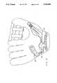
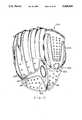
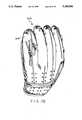
- FIGS. 1 and 2are front and rear elevational views of a baseball glove constructed in accordance with the primary embodiment of the invention.
- FIG. 3is a front elevational view similar to FIG. 1 but illustrating the wearer's hand within a glove shown in phantom lines and resting flat.
- FIG. 4is a view similar to FIG. 3 but showing an alternate embodiment of the invention.
- FIG. 5is a sectional view of the glove of FIGS. 1 through 3 and taken through the middle finger.
- FIG. 6is an elevational view of the pump system shown in the prior figures.
- FIG. 7is a partial sectional view taken along line 7--7 of FIG. 5.
- FIG. 8is a left side elevational view of the pump system of FIG. 7.
- FIG. 9is an elevational view of the fitting shown in FIGS. 6 through 8.
- FIG. 10is a sectional view of the fitting taken through line 10--10 of FIG. 9.
- FIGS. 11 and 12are front elevational views of gloves with bladders constructed in accordance with alternate embodiments of the invention.
- FIG. 13is a sectional view of the glove taken through the middle finger of the FIG. 12 embodiment.
- FIGS. 14, 15 and 16are front elevational views of bladders constructed in accordance with three additional alternate embodiments of the invention.
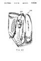
- FIGS. 17 through 20are front, back and side elevational views of a glove constructed in accordance with an additional embodiment of the invention.
- FIG. 21is a front elevational view of the glove shown in FIGS. 17 through 20 and illustrating the bladder in phantom lines.
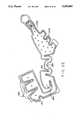
- FIG. 22is a front elevational view of the bladder itself.
- FIGS. 23 and 24are plan and front elevational views of the pump system employed in the glove of FIGS. 17 through 21.
- FIGS. 25 and 26are a plan and sectional view of a cover for the pump system of FIGS. 23 and 24.
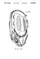
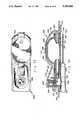
- FIGS. 27-30are perspective illustrations of a further embodiment of a inflatable baseball glove constructed in accordance with the principles of the present invention.
- FIG. 31is a plan view of the bladder of the glove of FIGS. 27-30.
- FIG. 32is a plan view of the bladder and glove of FIGS. 27-30.
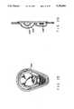
- FIGS. 33 and 34are a plan and sectional views of the air system assembly shown in FIGS. 31 and 32.
- FIGS. 35, 36 and 37are a perspective, plan and a side view of the cover for the air system assembly of FIGS. 33 and
- FIGS. 1 and 2Shown in FIGS. 1 and 2 is a game glove 10, as for baseball, softball or the like, having an inflatable bladder 12 constructed in accordance with the principles of the present invention.
- the glove 10is a generally conventional baseball glove in its design. It is fabricated of a plurality of pieces or layers 14, 16, etc. of material, preferably leather, front and back. The material defines a major region 20 for the receipt of the wearer's fingers and a minor region 22 for the receipt of the wearer's thumb.
- An opening 26is formed at the lower edge of the glove 10 between the front and back component pieces 14 and 16 through which the wearer may insert his hand into a hand space. Stitching and cords 28 couple the various pieces of the glove to render it a unitary device.
- the webbing 30Located between the thumb region and finger region of the glove are the webbing 30 at the upper extent and the well 32 at the lower extent which together form a pocket in which the ball is preferably caught.
- An aperture 34is formed in the back piece 16 through which the wearer may extend his index finger.
- the thumb region 22 and finger region 20are pivotable about the well and webbing areas by the movement of the wearer's thumb toward the fingers or the fingers towards the thumb to entrap the ball when being caught.
- the glove 10is essentially conventional in most regards except for a bladder 12 with an additional layer of material 38 interior of the glove for forming a bladder-receiving pocket 40 and a pump system 44 to inflate the bladder 12 with an aperture 46 in the glove 10 for exposing portions of the pump system.
- the glove 10 of the primary embodimentis shown in FIGS. 1 and 2 with the bladder 12 in dotted line configuration.
- the bladderis formed of two pieces 50 and 52 of air impervious elastomer, preferably urethane. Other similar light weight, air impervious, inflatable materials could readily be utilized.
- the two pieces of bladder materialare essentially of the same shape front and back and are heat sealed around their edges 54. In addition to the heat sealing around the edges, additional heat sealing is provided in the nature of dots 56. Such dots preclude the inflated bladder from becoming excessively thick. They also constitute built-in flex points at the knuckles or other joints of the wearer for the enhancement of glove bending and closure.
- the bladder 12is formed of two distinct major portions, the finger or major portion 60 and the thumb or minor portion 62 with an elongated coupling portion 64 therebetween.
- the finger portion 60has essentially linear parts 66 adapted to extend from near the central portion of the glove 10 upwardly into the fingers of the glove toward the tip ends of each finger of the glove. Such finger portions 66 of the bladder are adapted to be received in the lower extents of the fingers 68 of the glove.
- the thumb portion 70 of the bladderis also extended and adapted to be positioned within the lower extent of the thumb portion 72 of the glove 10.
- the thumb and finger portions of the bladderare each provided with a plurality of quilting dots 56 of heat sealing along the lengths thereof. Such dots add rigidity and support for the fingers and thumb. Flexibility is also enhanced due to their locations at the joints of the fingers and thumb as well as at the finger and thumb regions of the glove. A plurality of such dots 56 are also located in the coupling portion to keep the bladder portions together to a limited extent.
- the coupling portion 64 of the bladder 12is relatively thin simply to couple the thumb and finger portions 60 and 62 together for concurrent inflation and deflation. The dots also function to preclude excess ballooning of the bladder when in operation and use.
- FIG. 4is an alternate embodiment similar to FIG. 3.
- the coupling portion 64is located at the lowermost edge of the back of the glove.
- the coupling portion 65is raised slightly, midway between the lower edge of the glove and the lower edge of the finger opening 34 to give support to the back of the wearer's hand.
- FIG. 5is a cross sectional view of a portion of the bladder shown positioned within a glove, the glove being positioned on a wearer's hand.
- the deflated bladderis shown in solid lines while the inflated bladder is shown in dashed lines.
- Shown in the central extent of the gloveis the finger space 76, a portion of the hand space 78 for the wearer's hand.
- the front and back layers 14 and 16 of the glove as shown in FIGS. 1 and 2are also seen at the front and back of the FIG. 5 sectional view.
- an intermediate layer 80as of material such as leather or the like to separate the finger from additional padding 82 between such intermediate layer and the front piece.
- a layer of flexible material 38located behind the finger space is a layer of flexible material 38, as for example lamb skin or the like, which can breathe appropriately.
- the flexible material with the rear piece 16 of the gloveforms a pocket 40 in which the bladder 12 is located.
- the lower edge of the fabricencloses such pocket with the aid of a coupler such as adhesive or stitching to maintain the pocket closed.
- a releasable couplercould also be readily utilized.
- the lower edge of the bladdermay be stitched to the qlove.
- the bladder 12may be inflated to an appropriate extent through the use of the pump system 44. Similarly, the air may be selectively removed from the bladder. In this manner, the glove may be made to conform more securely to the wearer's hand so that upon catching the ball, jarring of the glove with respect to the hand is abated for increasing comfort, security and efficiency in catching balls.
- the pump system 44includes a pump or diaphragm 86, preferably blow molded, with associated check valves 88, 90 and a release valve 92, all interrelated with each other and with the bladder 12 to effect the desired result of selectively inflating and deflating the bladder for insuring proper fit of the particular glove to the particular wearer.
- the diaphragm 86is a one piece element formed of a resilient elastomeric material such as rubber, natural or synthetic or blend thereof. It is adapted to be depressed on its exposed exterior surface 94 by a user to decrease the volume of air within the diaphragm chamber. Upon release of the diaphragm, the volume of air within the chamber increases as the diaphragm returns to normal expand configuration as shown.
- each of the tubesreceives the exterior surfaces of one of the pair of check valves 88 and 90, preferably of the conventional duck-bill type.
- the upper check valve 90 as shown in FIG. 6is oriented to allow for the suction of air from the atmosphere to the chamber interior of the diaphragm 86 upon release of the diaphragm which, upon resiling of the diaphragm, increases the diaphragm chamber volume and generates a suction.
- a similarly configured but oppositely directed check valve 88is in operative association with the second tube 96 for the moving of air from interior of the diaphragm to the bladder upon depressing of the diaphragm which decreases the volume within the diaphragm chamber to increase the pressure therein.
- valves 88 and 90themselves are formed of elastomeric material, preferably silicone, with an aperture near the tip and a tube 102 of flexible, elastomeric material in a flat, ribbon-like configuration. Such arrangement constitutes a conventional duck-bill valve. Under normal conditions, each valve is such as to preclude the flow of air therethrough. When, however, a pressure differential is generated on opposite sides thereof through the depression or release of the diaphragm, the tube 102 of the check valves will open for the flow of air in one direction as shown by the arrows. Note FIG. 6. Upon the cessation of pumping, the tube 102 of each check valve will close to preclude further movement of air therethrough.
- the check valves 88 and 90are supported in a housing 104.
- the housingalso supports an adapter 112 which couples the diaphragm tubes with the one-way valves.
- the housing and the adapterare constructed of a rigid material preferably a plastic such as polyurethane.
- the housingincludes an upper aperture 106 in which is located a release ball 108.
- the release valve 92has an upper surface or button 110 adapted to be depressed by the user to force a stopper downwardly.
- the release ball 108is spherically shaped and seated in the aperture 106 which is correspondingly shaped. Downward movement of the button 110 and release ball 108 thus creates an opening between the stopper and the walls of the housing aperture for the release of the pressurized air within the bladder.
- a coil spring 114is located between the button 110 and the housing 104 to urge the stopper 108 upwardly upon the release of pressure generated by the finger of the operator to thereby retain the air within the bladder. Beneath the release ball 108 is a continuation of the air passage 118 for pneumatically coupling the bladder and the diaphragm.
- the housing 104is coupled with the bladder 12 as through an adhesive or welding and extends through an aperture 46 in the glove 10 to expose the diaphragm 86 and button 110. In this manner, the diaphragm is exposed so that it may be used by the wearer while the button of the release valve is similarly exposed, also for use by the wearer.
- FIGS. 11 and 12Alternate embodiments of the bladders are shown in FIGS. 11 and 12. Further alternate embodiments are shown in FIGS. 14, 15 and 16.
- the first alternate embodiment as shown in FIG. 11is a bladder 122 similar to the primary embodiment of FIGS. 1 through 3 except for the fact that the fingers 120 are more elongated than in the first embodiment, extending the full length of the fingers of the glove.
- heat sealing quiltingincludes lines 124 are provided in the bladder fingers and thumb for adding rigidity and strength to the glove in the region beyond the wearer's fingers and thumb.
- the inflatable bladder 128is actually a bladder system formed of a first or low pressure bladder 130 of a construction the same as or similar to that of the embodiment shown in FIGS. 1 through 3.
- a second or high pressure bladder 132is located in other regions of the glove.
- the high pressure bladder 132extends outwardly from the thumb and finger portions of the low pressure bladder 130 to fill the spaces of the glove previously unoccupied by thumb or fingers of the low pressure bladder.
- the purpose of the high pressure bladderis to add rigidity to the thumb and fingers of the gloves all the way to a location adjacent their tips 134, regions which are normally unsupported except for the strength and rigidity of the leather or other material of which the glove is fabricated. In this manner, the glove can be made of less expensive material or thinner constructions of conventional leathers for cost saving purposes.
- the second bladder 132should not be placed between the hand and glove in the location of the primary bladder since the excess pressure would cause discomfort to the wearer and possibly cut off circulation after extended use.
- no fingersare provided in the high pressure bladder adjacent to the middle and index finger of the wearer since the rigidity is mostly needed at the extremities of the glove beyond the thumb as well as the ring and little finger of the wearer. Flexibility is thus desirably extended to the central portion of the glove at the middle finger and index finger. In this manner, the entire glove and bladder are constructed to add maximum flexibility for the wearer when catching a ball.
- the primary bladderhas no finger component in the index finger area about which the thumb and other fingers pivot when catching a ball.
- the central connecting portion of the low pressure bladderis simply an extension of the sheets of air impervious material which constitute such bladder.
- a hollow tube 138connects the two portions of the high pressure bladder effecting a common pressure throughout the secondary bladders.
- a second pump 142is located on the back of the glove near the tip end of the little finger for inflating and deflating the high pressure bladder in a manner the same as for the first bladder but pneumatically independent thereof.
- the high pressure bladderis intended to be inflated to about 4 to 5 pounds per square inch while the low pressure bladder is intended to be inflated to about 2 to 3 pounds per square inch.
- each finger areais provided with a central opening 144 at its base in which is located the corresponding thumb and finger parts of the primary bladder.
- the two extreme fingers and thumb of the wearerare contacted by the primary bladder but surrounded by the secondary bladder for adding the desired rigidity to the glove without providing excess pressure to the wearer's hand.
- a sectional view of this embodiment, taken through the ring finger,is shown in FIG. 13.
- FIGS. 14, 15 and 16illustrate modified alternate designs for the primary bladder.
- the thumb and finger portions of the bladder 148are substantially the same as those in the embodiment of FIGS. 1 through 3, extending a length substantially equal to the wearer's fingers and thumb.
- the weld dots of such prior embodimentare replaced by weld lines 150 axially along the lengths of the thumb and finger portions.
- weld lines 152are provided in the back and retention area across the back of the wrist to preclude excessive enlargement of the primary bladder at such location.
- the FIG. 15 embodimentis a bladder 154 similar to FIG. 14 except that the fingers are of a shorter construction providing support only at the central portions of the fingers of the wearer. Specifically, the bladder is located to extend from above the knuckles, across the middle joints of the fingers and halfway to the outermost joints of the fingers. In addition, a modified air channel 156 provides for a more direct coupling between the wrist, thumb and finger regions of the bladder.
- the last embodiment, shown in FIG. 16,is a bladder 160 similar to FIG. 14 except that the central area 162 of the bladder, that coupling the thumb and fingers is enlarged to provide a back hand fill area to provide additional support to the central portion of the back of the wearer's hand above the wrist and beneath the knuckles or other bend points of the hand.
- the lowermost cross-piece 164is thereby located beneath the lowermost edge of a conventional glove, immediately above the wearer's wrist.
- the back of the gloveis extended downwardly, an increased amount as compared to conventional gloves, nearly to the wearer's wrist, for effecting the desired securement between the wearer's hand and glove.
- the back of the gloveis also extended downwardly, an increased amount as compared to conventional gloves, in order to accommodate the bladder or bladders.
- FIGS. 17 through 20are front and rear perspective illustrations of a further embodiment of a game glove 170 as for baseball, softball or the like, having an inflatable bladder 172 and constructed in accordance with another embodiment of the present invention.
- the gloveis provided with improved flexibility in various regions to render it more efficient for use with the bladder. Except for the flex points and the bladder, the glove is conventional in most regards. It does, as in prior embodiments, have a layer of material interior of the glove for forming a bladder-receiving pocket. It also has an inflation/deflation or pump system 174 to inflate and deflate the bladder with an aperture in the glove for exposing portions of the pump system for inflation and deflation purposes.
- FIG. 21shows the glove 170 with the bladder 172 in dotted line configuration.
- the bladderitself is more particularly seen in FIG. 22.
- the bladderis formed of two pieces and of an air impervious elastomer, preferably urethane. Other similar light weight, air impervious, inflatable materials could readily be utilized.
- the two pieces of bladder materialare essentially of the same shape front and back and are RF welded or otherwise coupled and sealed around their edges. In addition to the coupling around the edges, additional welding or heat sealing or quilting is provided in the nature of dots 178. Such quilting precludes the inflated bladder from becoming excessively thick and pillowing.
- the bladderis formed of two major portions, the finger or major portion 180 and the thumb or minor portion 182 with an elongated coupling portion 184 therebetween.
- the finger portionhas essentially linear parts 186 adapted to extend from near the central portion of the glove upwardly towards the fingers of the glove. Such finger portions correspond to the little finger, ring finger and middle finger.
- the finger portionsare adapted to overlie the back of the wearer's hand above the knuckle upwardly to below the end most joint.
- the thumb portion 182 of the bladderis also extended and adapted to be located adjacent to the lower extent of the thumb portion of the glove.
- the thumb and finger portions of the bladderare each provided with quilting dots 178 of heat sealing along the lengths thereof. Such dots add flexibility and support for the fingers and thumb while preventing pillowing. A plurality of such quilting dots are located in the thumb portion. A single quilting dot is located in each finger portion over the joint adjacent to the knuckle.
- the coupling portion of the bladderis relatively thin and functions to couple the thumb and finger portions together for concurrent inflation and deflation. Flexibility is also enhanced due to the locations of the finger and thumb regions of the bladder and glove in relationship to the joints of the fingers and thumb.
- the bladderIn the region between the portion of the bladder adjacent to the thumb and that portion adjacent to the finger, the bladder has two unique features or parts.
- the first part 188is the cross over area wherein the bladder connecting piece is bowed upwardly in an arc in the direction toward the fingers and away from the glove opening. This construction is to allow flexing of the glove about a vertical axis.
- the bladderincludes an enlarged part 190 beneath the back opening of the glove. This is to provide support to the back of the hand immediately beneath the knuckles, again for maximizing the secure coupling between the hand and glove without inhibiting movement of the wearer's hand joints.
- the areas of the glove different from conventional gloves and those of the prior embodimentsinclude a major cut out 194 in the lower back portion of the glove above the hand opening.
- This areaincludes a generally horizontal, lateral extent 196 tapering from the finger hole toward the base of the little finger. This extent also angles downwardly and covers the wearer's knuckles for added flexibility.
- Such openingalso has a vertical extent 200 which extends upwardly and downwardly from the finger hole 198 for improved flex about a vertical axis between the thumb and fingers of the wearer's hand.
- a flexible material 204as for example a neoprene sheet or knit nylon fabric, for providing limited extensibility upon the application of pressure as occurred through the inflation of the bladder.
- the materialis stitched to the interior of the glove around its periphery. Due to its location and properties, the material will provide a backing surface whereby bladder inflation will apply coupling forces between the glove due to the urging of the pocket material into pressure contact with the back of the wearer's hand with only limited stretching of the glove and its fabric. This effects maximum securement between glove and hand while still allowing for the flexibility required during use.
- cutouts 206are formed in the lower back of the glove, at the terminal ends of the webbing to supplement the flexibility provided by the fabric.
- openings 208are also located on the back side of the glove. These are shown as two sets of openings, each three in number, with the openings filled by fabric similar to that on the lower back side of the glove. In this manner, increased flexibility is allowed in the area adjacent the webbing functioning as a three piece web.
- Flexibilityis added to the front of the glove through the addition of generally vertical cut outs 212 with material covering the openings similar to the openings on the back side of the glove.
- the vertical front openingsare located on opposite sides of a central lower padding well 214.
- Such central lower paddingis a region with peripheral stitching 216 to contain a cushion-like padding material, as for example, felt in the conventional manner.
- laces 218are on opposite sides of the vertical front openings 212 which, with similar laces 220 around the periphery of the lower front padding, enhance the flex point of the glove at the bottom of the well.
- the padding on the edges and bottom of the glovethus function as three distinct pieces coupled to each other at flex lines.
- the pump systemincludes a pump or diaphragm 224 preferably rubber dip molded or blow or injection molded, with associated one way valves 226 and 228 and a release valve 230 all interrelated with each other and with the bladder to effect the desired result of selectively inflating and deflating the bladder for insuring proper fit of the particular glove to the particular wearer.
- the diaphragm 224is a one piece element formed of a resilient elastomeric material such as rubber, natural or synthetic or blend thereof. It is adapted to be depressed on its exposed exterior surface by a user to decrease the volume of air within the diaphragm chamber 234. Upon release of the diaphragm, the volume of air within the chamber increases as the diaphragm returns to normal expand configuration as shown.
- Axially aligned on opposite sides of the diaphragmare a pair of essentially rigid members, member 236 for conveying air from the interior of the diaphragm into the bladder and member 238 for conveying air from the atmosphere to interior of the diaphragm.
- the interior surface of each of the membersreceive the exterior surfaces of one of the pair of check valves 226 and 228 which are preferably of a conventional type.
- One check valve 228is a disc diaphragm valve, a commercially available valve, which is oriented to allow for the suction of air from the atmosphere to the chamber interior of the diaphragm upon release of the diaphragm.
- a duck bill, one way valve 226is an oppositely directed check valve. It is operative in association for the moving of air from interior of the diaphragm to the bladder upon depressing of the diaphragm which decreases the volume within the diaphragm chamber to increase the pressure therein.
- each valveis such as to preclude the flow of air therethrough.
- a pressure differentialis generated on opposite sides thereof through the depression or release of the diaphragm, the tube 102 of the check valves will open for the flow of air in one direction as shown by the arrows.
- the tube 102 of each check valvewill close to preclude further movement of air therethrough.
- the check valvesare supported in a housing 242.
- the housingalso supports an adapter 224 which couples the diaphragm tube with its the one-way valve.
- the housing and the adapterare constructed of a rigid material, preferably a plastic such as polyurethane. It includes an upper aperture in which is located a stopper or release ball 246.
- the release valvehas an upper surface or button 248 adapted to be depressed by the user to force a stopper downwardly.
- the release ballis spherically shaped and seated in the aperture 250 which is correspondingly shaped. Downward movement of the button against its spring 252 lowers the release ball to thus create an opening between the stopper and the walls of the housing aperture for the release of the pressurized air within the bladder.
- the coil springis located between the button and the housing to urge the stopper upwardly upon the release of pressure generated by the finger of the operator to thereby retain the air within the bladder. Beneath the release ball is a continuation of the air passage for pneumatically coupling the bladder and the diaphragm.
- the housingis coupled with the bladder as through an adhesive or welding and extends through an aperture in the glove to expose the diaphragm and button. In this manner, the diaphragm is exposed so that it may be used by the wearer while the button of the release valve is similarly exposed, also for use by the wearer.
- the diaphragm 224 and button 248are provided with a cover 254 of a flexible, resilient, elastomeric material.
- the diaphragm and buttonextend outwardly from the glove through a hole.
- the cover 254is sized and shaped to cover such diaphragm and button and is provided with a peripheral lip interior of the hole for stitching the cover to the glove hole periphery.
- the diaphragmcan be contracted and expanded to inflate the bladder by depressing on the upper half of the cover.
- the bladder pressuremay be relieved by pressing on the lower half of the cover adjacent to the button.
- the glove 302 of the final embodimentis similar to that shown in the prior figures in many regards. It has a major region 304 for the fingers of a wearer and a minor region 306 for the wearer's thumb.
- the inflatable bladder 310 behind the wearer's handincludes a major portion 312 adjacent to the finger region or portion 304 of the glove and a minor portion 314 adjacent to the thumb region or portion 306 of the glove with a coupling portion 316 therebetween.
- the bladder 310is formed of facing sheets of urethane or similar flexible, air impermeable material.
- the bladderincludes an extended periphery 320 adjacent to the edge of the glove with holes 322 which are adapted to receive the lacing strings 324 of the glove. This helps in retaining the bladder in position during use and allows proper placement of the bladder within the glove prior to stitching to the glove lining.
- the webbing 328is of a one piece construction with two elongated oval portions 330 extending generally vertically.
- Each oval portion 330is formed of superimposed material layers with apertures extending therethrough and with flexible mesh material 332 located between the layers. The ovals are on opposite sides of the vertical centerline of the webbing.
- such systemincludes an elastomeric diaphragm or pump bulb 338.
- diaphragm 338is preferably formed of latex, dip molded, and has a cylindrical input opening 340 and a cylindrical output opening 342 in axial alignment.
- the upper portion 344 of the bulbis generally oval in construction and adapted to be depressed and released by the user to pump air into the bladder 310. It is operatively coupled to the bladder adjacent to the output opening. It is operatively coupled to ambient air adjacent to the input opening.
- an inlet check valve 348is included.
- the inlet check valveincludes a cylindrical aperture 350 extending therethrough with an enlargement 352 at the neck for the receipt of an essentially rigid ball 354.
- the ballis positionable in the valve through flexible lips at the inner end of the inlet check valve 348.
- the ballis movable forwardly with the release of the diaphragm to allow air to enter the chamber 358 of the bulb.
- the ballis movable rearwardly to preclude air from escaping from the chamber to atmosphere when the diaphragm is depressed.
- a barb or ridge 360is circumferencially located and adapted to be received in an annular recess in the adjacent pump bulb opening for retaining the valve 348 in location.
- An adaptor valve 364is located at the output opening 342 of the pump bulb. Such valve 364 is adapted to communicate at its inboard end with the chamber 358 of the bulb and its outboard end with the bladder 310. A ridge 360 is received in an annular recess of the diaphragm similar to that in the inlet valve 348. A duckbill valve 366 with a circular cross section throughout the majority of its extent is received at the output end of the adapter valve 364. Its output end is tapered to a flat line 368 to allow the flow of air outwardly from the chamber toward the bladder for its filling in typical duckbill fashion.
- the check valve 348 and the adaptor valve 364are preferably fabricated of aluminum, screw machined parts, a material harder than the material of the diaphragm so that a secure coupling may be maintained therebetween.
- the entire output end of the pump bulbis received in a rigid elastomeric fitting 372.
- the fittingincludes a vertically disposed aperture 374 with a conical cross section.
- a release plunger 376 of a mating conical shapeis formed with a button 378 at its upper end positioned in the aperture.
- a spring 380is located between the plunger and fitting to urge the plunger upwardly and thereby preclude the loss of air from the bladder through the aperture in the fitting.
- Pinching the duckbill flangeno longer provides the primary seal around the duckbill. That seal is achieved by radially pinching the duckbill between the adapter valve and the fitting.
- the duckbill check valveis placed over a nipple at the output end of the adapter valve. This nipple is slightly larger than the inside diameter of the duckbill.
- the adapter-duckbill assemblyis then pressed into a hole in the fitting. The hole in the fitting is slightly smaller than the outside diameter of the duckbill.
- the entire air system assemblyis encompassed by a resilient rubber cover 384.
- the coverhas a major portion 386, oval in configuration, positionable over the pump bulb.
- the ovalhas its major axis parallel with the longitudinal axis of the glove thumb.
- the coveralso has a reduced section or minor portion 388 as its lower extent for positioning over the plunger. In this manner, the user may pump on the enlarged portion of the cover to periodically depress the bulb and thereby inflate the bladder to a desired pressure. Depression of the minor portion of the cover with its array of depressions 390, depresses the button and the plunger to allow the air to escape into the cover and outwardly through apertures on both sides thereof.
- openings 395 at the sides of the coverassists in allowing for the flow of air to and from the pump for inflation and deflation.
- One additional feature of the fittingis a plurality of downwardly extending legs 394, such legs function to hold the facing surfaces of the bladder spaced during inflation and deflation. This precludes the inadvertent stoppage of air flow in this region as would be caused by the bladder layers being in facing contact.
- the periphery of the coveris flat to form a flange 396.
- the flangeis located beneath the edge of a hole 398 in the glove through which the air system assembly and cover extends.
- a line of stitching between the glove and flangesecures the components of the system in place during operation and use.
- oval shapethere is limited width in the thumb of a glove.
- the pump cover and the lacinghave to lay side by side.
- An oval shapeincreased the pump's volume while decreasing its width.
- the reduced circumferential dimension of the diaphragmreduces the possibility of the cover inadvertently depressing the release button when a wearer squeezes the glove with its inflated bladder.
Landscapes
- Health & Medical Sciences (AREA)
- General Health & Medical Sciences (AREA)
- Physical Education & Sports Medicine (AREA)
- Gloves (AREA)
Abstract
Description
Claims (14)
Priority Applications (4)
| Application Number | Priority Date | Filing Date | Title |
|---|---|---|---|
| US07/803,279US5155866A (en) | 1991-04-23 | 1991-12-05 | Inflatable game gloves |
| KR1019920005680AKR920019383A (en) | 1991-04-23 | 1992-04-06 | Athletic Gloves with Inflatable Airbags |
| JP4129277AJPH05154227A (en) | 1991-04-23 | 1992-04-23 | Expandable glove for game |
| US07/955,191US5423088A (en) | 1991-04-23 | 1992-10-01 | Inflatable game gloves |
Applications Claiming Priority (3)
| Application Number | Priority Date | Filing Date | Title |
|---|---|---|---|
| US07/690,206US5155864A (en) | 1991-04-23 | 1991-04-23 | Inflatable bladders for game gloves |
| US07/728,476US5155865A (en) | 1991-04-23 | 1991-07-11 | Inflatable bladders for game gloves |
| US07/803,279US5155866A (en) | 1991-04-23 | 1991-12-05 | Inflatable game gloves |
Related Parent Applications (1)
| Application Number | Title | Priority Date | Filing Date |
|---|---|---|---|
| US07/728,476Continuation-In-PartUS5155865A (en) | 1991-04-23 | 1991-07-11 | Inflatable bladders for game gloves |
Related Child Applications (1)
| Application Number | Title | Priority Date | Filing Date |
|---|---|---|---|
| US07/955,191Continuation-In-PartUS5423088A (en) | 1991-04-23 | 1992-10-01 | Inflatable game gloves |
Publications (1)
| Publication Number | Publication Date |
|---|---|
| US5155866Atrue US5155866A (en) | 1992-10-20 |
Family
ID=27418526
Family Applications (2)
| Application Number | Title | Priority Date | Filing Date |
|---|---|---|---|
| US07/803,279Expired - LifetimeUS5155866A (en) | 1991-04-23 | 1991-12-05 | Inflatable game gloves |
| US07/955,191Expired - Fee RelatedUS5423088A (en) | 1991-04-23 | 1992-10-01 | Inflatable game gloves |
Family Applications After (1)
| Application Number | Title | Priority Date | Filing Date |
|---|---|---|---|
| US07/955,191Expired - Fee RelatedUS5423088A (en) | 1991-04-23 | 1992-10-01 | Inflatable game gloves |
Country Status (3)
| Country | Link |
|---|---|
| US (2) | US5155866A (en) |
| JP (1) | JPH05154227A (en) |
| KR (1) | KR920019383A (en) |
Cited By (26)
| Publication number | Priority date | Publication date | Assignee | Title |
|---|---|---|---|---|
| WO1994010868A1 (en)* | 1992-11-09 | 1994-05-26 | Reebok International Ltd. | Inflation mechanism for an inflatable article of manufacture |
| US5325539A (en)* | 1992-08-07 | 1994-07-05 | American Needle | Headwear piece with cover for size adjustment actuator |
| US5367712A (en)* | 1992-09-30 | 1994-11-29 | Alexander, Smith & Co. | System for changing the shape or fit of glove |
| USD357974S (en) | 1993-10-13 | 1995-05-02 | Reebok International Ltd. | Connector for use with an inflation mechanism |
| US5423088A (en)* | 1991-04-23 | 1995-06-13 | Lisco, Inc. | Inflatable game gloves |
| US5575005A (en)* | 1995-02-03 | 1996-11-19 | Lisco, Inc. | Baseball or softball glove having elastic liner |
| US6202213B1 (en) | 1999-09-03 | 2001-03-20 | John J. Georgick | Boxing glove with inflatable wrist cuff |
| US6785985B2 (en) | 2002-07-02 | 2004-09-07 | Reebok International Ltd. | Shoe having an inflatable bladder |
| US7278445B2 (en) | 2002-07-02 | 2007-10-09 | Reebok International Ltd. | Shoe having an inflatable bladder |
| US7622014B2 (en) | 2005-07-01 | 2009-11-24 | Reebok International Ltd. | Method for manufacturing inflatable footwear or bladders for use in inflatable articles |
| US7694438B1 (en) | 2006-12-13 | 2010-04-13 | Reebok International Ltd. | Article of footwear having an adjustable ride |
| US7784196B1 (en) | 2006-12-13 | 2010-08-31 | Reebok International Ltd. | Article of footwear having an inflatable ground engaging surface |
| US7934521B1 (en) | 2006-12-20 | 2011-05-03 | Reebok International, Ltd. | Configurable fluid transfer manifold for inflatable footwear |
| US8037623B2 (en) | 2001-06-21 | 2011-10-18 | Nike, Inc. | Article of footwear incorporating a fluid system |
| US20120180191A1 (en)* | 2011-01-14 | 2012-07-19 | Nike, Inc. | Glove With Thermally Moldable Shaping Inserts |
| US8230874B2 (en) | 2006-12-20 | 2012-07-31 | Reebok International Limited | Configurable fluid transfer manifold for inflatable footwear |
| US8256141B2 (en) | 2006-12-13 | 2012-09-04 | Reebok International Limited | Article of footwear having an adjustable ride |
| US20120246788A1 (en)* | 2011-03-28 | 2012-10-04 | Harrell Jeremy L | Multipurpose Cooling and Trauma Attenuating Devices and Associated Methods |
| US8414275B1 (en) | 2007-01-11 | 2013-04-09 | Reebok International Limited | Pump and valve combination for an article of footwear incorporating an inflatable bladder |
| US8572786B2 (en) | 2010-10-12 | 2013-11-05 | Reebok International Limited | Method for manufacturing inflatable bladders for use in footwear and other articles of manufacture |
| US8677652B2 (en) | 2002-07-02 | 2014-03-25 | Reebok International Ltd. | Shoe having an inflatable bladder |
| USD731122S1 (en) | 2013-01-14 | 2015-06-02 | Jeremy L. Harrell | Inflatable pad |
| USD738577S1 (en) | 2013-01-14 | 2015-09-08 | Jeremy L. Harrell | Inflatable pad pattern |
| USD738576S1 (en) | 2013-01-14 | 2015-09-08 | Jeremy L. Harrell | Inflatable pad pattern |
| USD743633S1 (en) | 2013-01-14 | 2015-11-17 | Jeremy L. Harrell | Inflatable pad pattern |
| USD890998S1 (en)* | 2016-07-20 | 2020-07-21 | Earl Stanley Cook, Sr. | Wrist grips and protector for a baseball glove |
Families Citing this family (12)
| Publication number | Priority date | Publication date | Assignee | Title |
|---|---|---|---|---|
| USD417757S (en)* | 1998-09-30 | 1999-12-14 | Rawlings Sporting Goods Company, Inc. | Baseball glove |
| USD420174S (en)* | 1998-11-12 | 2000-02-01 | Rawlings Sporting Goods Company, Inc. | Baseball glove |
| USD420173S (en)* | 1998-11-12 | 2000-02-01 | Rawlings Sporting Goods Company, Inc. | Baseball glove |
| US6308331B1 (en)* | 1998-12-09 | 2001-10-30 | Tim Robak | Inflatable baseball glove |
| USD530454S1 (en)* | 2005-04-07 | 2006-10-17 | Rawlings Sporting Goods Company, Inc. | Ball glove |
| USD531361S1 (en)* | 2005-04-07 | 2006-10-31 | Rawlings Sportings Goods Company, Inc. | Ball glove |
| USD531362S1 (en)* | 2005-04-07 | 2006-10-31 | Rawlings Sporting Goods Company, Inc. | Ball glove |
| USD531363S1 (en)* | 2005-04-07 | 2006-10-31 | Rawlings Sporting Goods Company, Inc. | Ball glove |
| GB0614356D0 (en)* | 2006-07-19 | 2006-08-30 | Teardrop Technologies Ltd | Sports glove |
| US8656513B2 (en)* | 2008-09-22 | 2014-02-25 | Nike, Inc. | Sports glove with impact force attenuation system |
| USD665538S1 (en)* | 2010-02-16 | 2012-08-14 | James Edward Jennings | Baseball glove shell |
| JP6829279B2 (en)* | 2019-03-14 | 2021-02-10 | トライオン株式会社 | Catch tool |
Citations (98)
| Publication number | Priority date | Publication date | Assignee | Title |
|---|---|---|---|---|
| US320972A (en)* | 1885-06-30 | Boxing-glove | ||
| US450717A (en)* | 1891-04-21 | Robert reach | ||
| US531872A (en)* | 1895-01-01 | Boxing-glove | ||
| US570092A (en)* | 1896-10-27 | Boxing-glove | ||
| US600779A (en)* | 1898-03-15 | Boxing-glove | ||
| US746338A (en)* | 1902-11-06 | 1903-12-08 | Charles H Williams | Anatomical guard, boot, or pad. |
| US812921A (en)* | 1904-11-15 | 1906-02-20 | George J Stiteley | Base-ball glove. |
| US972224A (en)* | 1910-05-16 | 1910-10-11 | Herbert H Pease | Slapping-glove. |
| US1053204A (en)* | 1910-10-12 | 1913-02-18 | William A Morrison | Hygienic mitten. |
| GB104402A (en)* | 1916-03-18 | 1917-03-08 | Charles Tuckfield | Improvements in Reaming and Drilling Machinery. |
| US1362280A (en)* | 1919-08-05 | 1920-12-14 | Robert H Young | Baseball mitt and glove |
| US1465223A (en)* | 1922-04-29 | 1923-08-14 | Kobbe Edward | Handband or protector for baseball players |
| US1602027A (en)* | 1926-06-09 | 1926-10-05 | Daniel J Kennedy | Catcher's glove |
| US1622322A (en)* | 1926-08-23 | 1927-03-29 | Daniel J Kennedy | Boxing glove |
| US1954122A (en)* | 1932-04-28 | 1934-04-10 | John M Fiori | Boot |
| US1974616A (en)* | 1932-10-31 | 1934-09-25 | Kenzie K Kirkham | Athletic glove or mitt construction |
| US2135853A (en)* | 1937-07-17 | 1938-11-08 | Slizus Joseph | Pneumatic boxing glove |
| US2275206A (en)* | 1939-10-26 | 1942-03-03 | Sutherland Frederick Henery | Pneumatic boxing glove |
| US2638690A (en)* | 1950-05-29 | 1953-05-19 | Iii Edward P Bullard | Article of footwear |
| US2653319A (en)* | 1949-07-07 | 1953-09-29 | Slizus Joseph | Pneumatic boxing glove |
| US2817088A (en)* | 1955-07-13 | 1957-12-24 | Vrana Charles | Air inflated boxing gloves |
| US2830585A (en)* | 1955-04-21 | 1958-04-15 | Efram I Weiss | Ankle support |
| US2881445A (en)* | 1957-02-08 | 1959-04-14 | Vrana Charles | Combination inner and outer inflated boxing glove |
| US2981010A (en)* | 1960-05-13 | 1961-04-25 | Aaskov Helmer | Air-filled sandals |
| US3217333A (en)* | 1963-08-09 | 1965-11-16 | Don A Sweet | Pneumatic boxing glove |
| GB1037730A (en)* | 1964-07-17 | 1966-08-03 | Daimler Benz Ag | Improvements relating to driver's cabs for motor vehicles |
| GB1037729A (en)* | 1964-04-30 | 1966-08-03 | Edouard Jean Pierre Calvet | Improvements relating to microcalorimeters having thermo-element-semi-conductors |
| GB1037728A (en)* | 1964-02-12 | 1966-08-03 | Kearney & Trecker Corp | Machine tool with travelling tool changer |
| GB1037685A (en)* | 1962-03-22 | 1966-08-03 | Standard Telephones Cables Ltd | High speed electronic switching telephone system |
| GB1041132A (en)* | 1963-06-04 | 1966-09-01 | Andre Remy Moynet | Improvements relating to the propulsion of aircraft |
| GB1044031A (en)* | 1962-04-17 | 1966-09-28 | Universal Moulded Fiber Glass | Production of articles composed of fiber reinforced resin materials |
| GB1044032A (en)* | 1962-05-09 | 1966-09-28 | Scott Inc H H | Balanced stereophonic demodulator apparatus |
| GB1044026A (en)* | 1962-04-15 | 1966-09-28 | Yissum Res Dev Co | Grazing incidence vacuum spectrometer |
| GB1044030A (en)* | 1963-12-06 | 1966-09-28 | Gen Electric Co Ltd | Improvements in or relating to telephone instruments |
| GB1044029A (en)* | 1963-11-08 | 1966-09-28 | Irish Maltsters Ass | A new and improved malting plant |
| GB1044033A (en)* | 1962-04-17 | 1966-09-28 | Dubied & Cie Sa E | Improvements in or relating to the knitted collars |
| GB1044027A (en)* | 1963-05-10 | 1966-09-28 | Amplivox Ltd | Improvements in and relating to hearing aids |
| GB1056365A (en)* | 1964-05-11 | 1967-01-25 | Ncr Co | A heat and/or pressure sensitive record material unit |
| US3602915A (en)* | 1969-12-19 | 1971-09-07 | Ato Inc | Baseball mitt or glove |
| US3605117A (en)* | 1970-01-30 | 1971-09-20 | Ato Inc | Hockey gloves |
| US3623163A (en)* | 1970-01-16 | 1971-11-30 | Ato Inc | Backstop for a ball glove |
| US3664043A (en)* | 1970-10-14 | 1972-05-23 | Emile A Polumbus Jr | Accessory for footwear |
| US3685176A (en)* | 1970-07-02 | 1972-08-22 | Marion F Rudy | Inflatable article of footwear |
| US3841304A (en)* | 1972-10-16 | 1974-10-15 | A Jones | Inflatable leakage inhibitor |
| US3854228A (en)* | 1972-05-02 | 1974-12-17 | R Conroy | Athletic armor and inflatable bag assembly |
| US3926175A (en)* | 1974-06-03 | 1975-12-16 | James H Allen | Implantable valve for medical purposes |
| US4067063A (en)* | 1975-03-31 | 1978-01-10 | Ettinger Donald N | Pneumatic athletic guard |
| US4128951A (en)* | 1975-05-07 | 1978-12-12 | Falk Construction, Inc. | Custom-formed insert |
| GB2000234A (en)* | 1977-06-27 | 1979-01-04 | Occident Ets | Fluid sealing arrangement |
| GB2000086A (en)* | 1977-06-30 | 1979-01-04 | Edholm E | Collapsible wheelchair undercarriage |
| GB2000087A (en)* | 1977-06-17 | 1979-01-04 | Firestone Tire & Rubber Co | Vehicle wheels |
| GB2003612A (en)* | 1977-09-01 | 1979-03-14 | Insele Oy | Domestic heating measurement and control |
| GB2005392A (en)* | 1977-10-05 | 1979-04-19 | Raypak Produkten Nv | Gas-fired boiler installation with draft inerrupter |
| GB2009887A (en)* | 1977-12-13 | 1979-06-20 | Ustav Pro Vyzkum Motorovych Vo | Device for an axial location of an inner shaft of a universal joint |
| GB2009889A (en)* | 1977-12-13 | 1979-06-20 | Chauvier F | Valve |
| GB2009888A (en)* | 1977-12-12 | 1979-06-20 | Sigma Enterprises Inc | Shut-off valve |
| GB2009886A (en)* | 1977-11-07 | 1979-06-20 | Agfa Gevaert Ag | Transport rollers especially for electrostatic photocopying apparatus |
| GB2009890A (en)* | 1977-12-13 | 1979-06-20 | Daimler Benz Ag | Thermostatic control valves |
| GB2013018A (en)* | 1978-01-20 | 1979-08-01 | Nissan Motor | Navigational information announcing system for motor vehicle |
| US4192018A (en)* | 1978-04-14 | 1980-03-11 | A-T-O Inc. | Baseball glove |
| US4232459A (en)* | 1977-11-02 | 1980-11-11 | Franco Vaccari | Ski boots |
| US4346481A (en)* | 1981-02-26 | 1982-08-31 | A-T-O Inc. | Baseball mitt |
| US4358902A (en)* | 1980-04-02 | 1982-11-16 | Cole George S | Thrust producing shoe sole and heel |
| US4361969A (en)* | 1979-12-28 | 1982-12-07 | Societe A Responsabilite Limitee Technisynthese | Shoe with pneumatic cushioning chamber |
| US4370754A (en)* | 1978-07-27 | 1983-02-01 | American Pneumatics Co. | Variable pressure pad |
| US4397104A (en)* | 1981-01-23 | 1983-08-09 | Doak Clayton R | Inflatable sole-shoe |
| US4446634A (en)* | 1982-09-28 | 1984-05-08 | Johnson Paul H | Footwear having improved shock absorption |
| US4449520A (en)* | 1982-09-02 | 1984-05-22 | Palomar Juan M | Penile prosthesis device |
| US4453272A (en)* | 1981-05-30 | 1984-06-12 | Mizuno Corporation | Baseball glove |
| US4477927A (en)* | 1982-02-08 | 1984-10-23 | Mizuno Corporation | Baseball glove |
| US4483022A (en)* | 1982-06-14 | 1984-11-20 | Mizuno Corporation | Baseball glove |
| US4486975A (en)* | 1983-09-12 | 1984-12-11 | Vonco Products, Inc. | Inflatable novelty device |
| US4527287A (en)* | 1983-06-24 | 1985-07-09 | Figgie International Inc. | Baseball glove or mitt |
| USD280462S (en) | 1983-06-24 | 1985-09-10 | Figgie International Inc. | Baseball glove |
| DE3427644A1 (en)* | 1983-03-24 | 1986-01-30 | Josef 8069 Jetzendorf Lederer | Ski boot |
| US4611584A (en)* | 1980-05-15 | 1986-09-16 | Medical Engineering Corp. | Expandable penile implant |
| US4643733A (en)* | 1983-04-04 | 1987-02-17 | Hilton Becker | Permanent reconstruction implant and method of performing human tissue expansion |
| US4651345A (en)* | 1986-05-29 | 1987-03-24 | Figgie International Inc. | Wrist strap construction for a baseball glove |
| DE3600437A1 (en)* | 1986-01-09 | 1987-07-16 | Josef Lederer | SKI SHOE KEYWORD: DOUBLE PUMP |
| US4702022A (en)* | 1985-10-11 | 1987-10-27 | Porcher Pierre O | Ski boot |
| US4712316A (en)* | 1985-09-09 | 1987-12-15 | Nordica S.P.A. | Ski boot with a device for securing the foot of the skier |
| US4720403A (en)* | 1986-08-07 | 1988-01-19 | Desoto, Inc. | Anticorrosive coating compositions |
| US4730403A (en)* | 1985-07-24 | 1988-03-15 | Raichle Sportschuh Ag | Pressurized ski boot |
| US4763426A (en)* | 1986-04-18 | 1988-08-16 | Michael Polus | Sport shoe with pneumatic inflating device |
| USD300182S (en) | 1986-08-18 | 1989-03-14 | Figgie International Inc. | Back wall for a baseball glove |
| US4846784A (en)* | 1987-07-01 | 1989-07-11 | C. R. Bard, Inc. | Manually adjustable sphincteric system |
| US4847915A (en)* | 1988-05-09 | 1989-07-18 | Figgie International, Inc. | Baseball glove with a flexible heel construction |
| US4852287A (en)* | 1988-09-29 | 1989-08-01 | Maurice Martin | Shooters head immobilizing apparatus |
| US4853975A (en)* | 1988-04-11 | 1989-08-08 | Figgie International Inc. | Catcher's mitt |
| US4887367A (en)* | 1987-07-09 | 1989-12-19 | Hi-Tec Sports Plc | Shock absorbing shoe sole and shoe incorporating the same |
| US4908880A (en)* | 1988-04-15 | 1990-03-20 | Figgie International Inc. | Baseball glove or mitt |
| US4912861A (en)* | 1988-04-11 | 1990-04-03 | Huang Ing Chung | Removable pressure-adjustable shock-absorbing cushion device with an inflation pump for sports goods |
| US4947486A (en)* | 1989-01-13 | 1990-08-14 | Fairdon Industrial Limited | Glove liner apparatus |
| USD310739S (en) | 1988-04-15 | 1990-09-18 | Figgie International Inc. | Web for a baseball glove |
| US4995173A (en)* | 1989-04-13 | 1991-02-26 | Leonard Cooper | High tech footwear |
| US4999932A (en)* | 1989-02-14 | 1991-03-19 | Royce Medical Company | Variable support shoe |
| USD315620S (en) | 1986-12-29 | 1991-03-19 | Figgie International Inc. | Web for a ball glove |
| US5075899A (en)* | 1989-07-21 | 1991-12-31 | Mizuno Corporation | Ball-catching glove for use in baseball and softball |
Family Cites Families (14)
| Publication number | Priority date | Publication date | Assignee | Title |
|---|---|---|---|---|
| US2744152A (en)* | 1954-10-28 | 1956-05-01 | Gen Electric | Electric furnace with carbonaceous atmosphere |
| US2842771A (en)* | 1957-05-17 | 1958-07-15 | Foti Peter | Insulated glove |
| GB1037732A (en)* | 1961-09-15 | 1966-08-03 | F H Lloyd And Company Ltd | Refractory paint |
| GB1044028A (en)* | 1962-07-24 | 1966-09-28 | Grace W R & Co | Improvements relating to filled polyolefine |
| FR2413302A1 (en) | 1977-12-29 | 1979-07-27 | Decaux Paris J C | TAPE WINDING DEVICE, ESPECIALLY FOR DISPLAY PANEL WITH MOBILE POSTERS |
| US4453271A (en)* | 1979-09-28 | 1984-06-12 | American Pneumatics Co. | Protective garment |
| DE3326085C2 (en)* | 1983-07-20 | 1987-01-08 | Reusch & Sohn Verwaltungsgesellschaft mbH, 7430 Metzingen | Protective glove |
| EP0298449A3 (en)* | 1987-07-06 | 1989-08-23 | Reebok International Ltd. | Tubular cushioning system for shoes |
| JPS6437730A (en)* | 1987-08-03 | 1989-02-08 | Ricoh Kk | Optical information recording and reproducing device |
| US5113599A (en)* | 1989-02-08 | 1992-05-19 | Reebok International Ltd. | Athletic shoe having inflatable bladder |
| US4937882A (en)* | 1988-02-22 | 1990-07-03 | Rufus Hayes | Baseball gloves and attachments therefor |
| US5155864A (en)* | 1991-04-23 | 1992-10-20 | Lisco, Inc. | Inflatable bladders for game gloves |
| US5155866A (en)* | 1991-04-23 | 1992-10-20 | Lisco, Inc. | Inflatable game gloves |
| US5155865A (en)* | 1991-04-23 | 1992-10-20 | Lisco, Inc. | Inflatable bladders for game gloves |
- 1991
- 1991-12-05USUS07/803,279patent/US5155866A/ennot_activeExpired - Lifetime
- 1992
- 1992-04-06KRKR1019920005680Apatent/KR920019383A/ennot_activeWithdrawn
- 1992-04-23JPJP4129277Apatent/JPH05154227A/enactivePending
- 1992-10-01USUS07/955,191patent/US5423088A/ennot_activeExpired - Fee Related
Patent Citations (98)
| Publication number | Priority date | Publication date | Assignee | Title |
|---|---|---|---|---|
| US320972A (en)* | 1885-06-30 | Boxing-glove | ||
| US450717A (en)* | 1891-04-21 | Robert reach | ||
| US531872A (en)* | 1895-01-01 | Boxing-glove | ||
| US570092A (en)* | 1896-10-27 | Boxing-glove | ||
| US600779A (en)* | 1898-03-15 | Boxing-glove | ||
| US746338A (en)* | 1902-11-06 | 1903-12-08 | Charles H Williams | Anatomical guard, boot, or pad. |
| US812921A (en)* | 1904-11-15 | 1906-02-20 | George J Stiteley | Base-ball glove. |
| US972224A (en)* | 1910-05-16 | 1910-10-11 | Herbert H Pease | Slapping-glove. |
| US1053204A (en)* | 1910-10-12 | 1913-02-18 | William A Morrison | Hygienic mitten. |
| GB104402A (en)* | 1916-03-18 | 1917-03-08 | Charles Tuckfield | Improvements in Reaming and Drilling Machinery. |
| US1362280A (en)* | 1919-08-05 | 1920-12-14 | Robert H Young | Baseball mitt and glove |
| US1465223A (en)* | 1922-04-29 | 1923-08-14 | Kobbe Edward | Handband or protector for baseball players |
| US1602027A (en)* | 1926-06-09 | 1926-10-05 | Daniel J Kennedy | Catcher's glove |
| US1622322A (en)* | 1926-08-23 | 1927-03-29 | Daniel J Kennedy | Boxing glove |
| US1954122A (en)* | 1932-04-28 | 1934-04-10 | John M Fiori | Boot |
| US1974616A (en)* | 1932-10-31 | 1934-09-25 | Kenzie K Kirkham | Athletic glove or mitt construction |
| US2135853A (en)* | 1937-07-17 | 1938-11-08 | Slizus Joseph | Pneumatic boxing glove |
| US2275206A (en)* | 1939-10-26 | 1942-03-03 | Sutherland Frederick Henery | Pneumatic boxing glove |
| US2653319A (en)* | 1949-07-07 | 1953-09-29 | Slizus Joseph | Pneumatic boxing glove |
| US2638690A (en)* | 1950-05-29 | 1953-05-19 | Iii Edward P Bullard | Article of footwear |
| US2830585A (en)* | 1955-04-21 | 1958-04-15 | Efram I Weiss | Ankle support |
| US2817088A (en)* | 1955-07-13 | 1957-12-24 | Vrana Charles | Air inflated boxing gloves |
| US2881445A (en)* | 1957-02-08 | 1959-04-14 | Vrana Charles | Combination inner and outer inflated boxing glove |
| US2981010A (en)* | 1960-05-13 | 1961-04-25 | Aaskov Helmer | Air-filled sandals |
| GB1037685A (en)* | 1962-03-22 | 1966-08-03 | Standard Telephones Cables Ltd | High speed electronic switching telephone system |
| GB1044026A (en)* | 1962-04-15 | 1966-09-28 | Yissum Res Dev Co | Grazing incidence vacuum spectrometer |
| GB1044031A (en)* | 1962-04-17 | 1966-09-28 | Universal Moulded Fiber Glass | Production of articles composed of fiber reinforced resin materials |
| GB1044033A (en)* | 1962-04-17 | 1966-09-28 | Dubied & Cie Sa E | Improvements in or relating to the knitted collars |
| GB1044032A (en)* | 1962-05-09 | 1966-09-28 | Scott Inc H H | Balanced stereophonic demodulator apparatus |
| GB1044027A (en)* | 1963-05-10 | 1966-09-28 | Amplivox Ltd | Improvements in and relating to hearing aids |
| GB1041132A (en)* | 1963-06-04 | 1966-09-01 | Andre Remy Moynet | Improvements relating to the propulsion of aircraft |
| US3217333A (en)* | 1963-08-09 | 1965-11-16 | Don A Sweet | Pneumatic boxing glove |
| GB1044029A (en)* | 1963-11-08 | 1966-09-28 | Irish Maltsters Ass | A new and improved malting plant |
| GB1044030A (en)* | 1963-12-06 | 1966-09-28 | Gen Electric Co Ltd | Improvements in or relating to telephone instruments |
| GB1037728A (en)* | 1964-02-12 | 1966-08-03 | Kearney & Trecker Corp | Machine tool with travelling tool changer |
| GB1037729A (en)* | 1964-04-30 | 1966-08-03 | Edouard Jean Pierre Calvet | Improvements relating to microcalorimeters having thermo-element-semi-conductors |
| GB1056365A (en)* | 1964-05-11 | 1967-01-25 | Ncr Co | A heat and/or pressure sensitive record material unit |
| GB1037730A (en)* | 1964-07-17 | 1966-08-03 | Daimler Benz Ag | Improvements relating to driver's cabs for motor vehicles |
| US3602915A (en)* | 1969-12-19 | 1971-09-07 | Ato Inc | Baseball mitt or glove |
| US3623163A (en)* | 1970-01-16 | 1971-11-30 | Ato Inc | Backstop for a ball glove |
| US3605117A (en)* | 1970-01-30 | 1971-09-20 | Ato Inc | Hockey gloves |
| US3685176A (en)* | 1970-07-02 | 1972-08-22 | Marion F Rudy | Inflatable article of footwear |
| US3664043A (en)* | 1970-10-14 | 1972-05-23 | Emile A Polumbus Jr | Accessory for footwear |
| US3854228A (en)* | 1972-05-02 | 1974-12-17 | R Conroy | Athletic armor and inflatable bag assembly |
| US3841304A (en)* | 1972-10-16 | 1974-10-15 | A Jones | Inflatable leakage inhibitor |
| US3926175A (en)* | 1974-06-03 | 1975-12-16 | James H Allen | Implantable valve for medical purposes |
| US4067063A (en)* | 1975-03-31 | 1978-01-10 | Ettinger Donald N | Pneumatic athletic guard |
| US4128951A (en)* | 1975-05-07 | 1978-12-12 | Falk Construction, Inc. | Custom-formed insert |
| GB2000087A (en)* | 1977-06-17 | 1979-01-04 | Firestone Tire & Rubber Co | Vehicle wheels |
| GB2000234A (en)* | 1977-06-27 | 1979-01-04 | Occident Ets | Fluid sealing arrangement |
| GB2000086A (en)* | 1977-06-30 | 1979-01-04 | Edholm E | Collapsible wheelchair undercarriage |
| GB2003612A (en)* | 1977-09-01 | 1979-03-14 | Insele Oy | Domestic heating measurement and control |
| GB2005392A (en)* | 1977-10-05 | 1979-04-19 | Raypak Produkten Nv | Gas-fired boiler installation with draft inerrupter |
| US4232459A (en)* | 1977-11-02 | 1980-11-11 | Franco Vaccari | Ski boots |
| GB2009886A (en)* | 1977-11-07 | 1979-06-20 | Agfa Gevaert Ag | Transport rollers especially for electrostatic photocopying apparatus |
| GB2009888A (en)* | 1977-12-12 | 1979-06-20 | Sigma Enterprises Inc | Shut-off valve |
| GB2009889A (en)* | 1977-12-13 | 1979-06-20 | Chauvier F | Valve |
| GB2009890A (en)* | 1977-12-13 | 1979-06-20 | Daimler Benz Ag | Thermostatic control valves |
| GB2009887A (en)* | 1977-12-13 | 1979-06-20 | Ustav Pro Vyzkum Motorovych Vo | Device for an axial location of an inner shaft of a universal joint |
| GB2013018A (en)* | 1978-01-20 | 1979-08-01 | Nissan Motor | Navigational information announcing system for motor vehicle |
| US4192018A (en)* | 1978-04-14 | 1980-03-11 | A-T-O Inc. | Baseball glove |
| US4370754A (en)* | 1978-07-27 | 1983-02-01 | American Pneumatics Co. | Variable pressure pad |
| US4361969A (en)* | 1979-12-28 | 1982-12-07 | Societe A Responsabilite Limitee Technisynthese | Shoe with pneumatic cushioning chamber |
| US4358902A (en)* | 1980-04-02 | 1982-11-16 | Cole George S | Thrust producing shoe sole and heel |
| US4611584A (en)* | 1980-05-15 | 1986-09-16 | Medical Engineering Corp. | Expandable penile implant |
| US4397104A (en)* | 1981-01-23 | 1983-08-09 | Doak Clayton R | Inflatable sole-shoe |
| US4346481A (en)* | 1981-02-26 | 1982-08-31 | A-T-O Inc. | Baseball mitt |
| US4453272A (en)* | 1981-05-30 | 1984-06-12 | Mizuno Corporation | Baseball glove |
| US4477927A (en)* | 1982-02-08 | 1984-10-23 | Mizuno Corporation | Baseball glove |
| US4483022A (en)* | 1982-06-14 | 1984-11-20 | Mizuno Corporation | Baseball glove |
| US4449520A (en)* | 1982-09-02 | 1984-05-22 | Palomar Juan M | Penile prosthesis device |
| US4446634A (en)* | 1982-09-28 | 1984-05-08 | Johnson Paul H | Footwear having improved shock absorption |
| DE3427644A1 (en)* | 1983-03-24 | 1986-01-30 | Josef 8069 Jetzendorf Lederer | Ski boot |
| US4643733A (en)* | 1983-04-04 | 1987-02-17 | Hilton Becker | Permanent reconstruction implant and method of performing human tissue expansion |
| USD280462S (en) | 1983-06-24 | 1985-09-10 | Figgie International Inc. | Baseball glove |
| US4527287A (en)* | 1983-06-24 | 1985-07-09 | Figgie International Inc. | Baseball glove or mitt |
| US4486975A (en)* | 1983-09-12 | 1984-12-11 | Vonco Products, Inc. | Inflatable novelty device |
| US4730403A (en)* | 1985-07-24 | 1988-03-15 | Raichle Sportschuh Ag | Pressurized ski boot |
| US4712316A (en)* | 1985-09-09 | 1987-12-15 | Nordica S.P.A. | Ski boot with a device for securing the foot of the skier |
| US4702022A (en)* | 1985-10-11 | 1987-10-27 | Porcher Pierre O | Ski boot |
| DE3600437A1 (en)* | 1986-01-09 | 1987-07-16 | Josef Lederer | SKI SHOE KEYWORD: DOUBLE PUMP |
| US4763426A (en)* | 1986-04-18 | 1988-08-16 | Michael Polus | Sport shoe with pneumatic inflating device |
| US4651345A (en)* | 1986-05-29 | 1987-03-24 | Figgie International Inc. | Wrist strap construction for a baseball glove |
| US4720403A (en)* | 1986-08-07 | 1988-01-19 | Desoto, Inc. | Anticorrosive coating compositions |
| USD300182S (en) | 1986-08-18 | 1989-03-14 | Figgie International Inc. | Back wall for a baseball glove |
| USD315620S (en) | 1986-12-29 | 1991-03-19 | Figgie International Inc. | Web for a ball glove |
| US4846784A (en)* | 1987-07-01 | 1989-07-11 | C. R. Bard, Inc. | Manually adjustable sphincteric system |
| US4887367A (en)* | 1987-07-09 | 1989-12-19 | Hi-Tec Sports Plc | Shock absorbing shoe sole and shoe incorporating the same |
| US4853975A (en)* | 1988-04-11 | 1989-08-08 | Figgie International Inc. | Catcher's mitt |
| US4912861A (en)* | 1988-04-11 | 1990-04-03 | Huang Ing Chung | Removable pressure-adjustable shock-absorbing cushion device with an inflation pump for sports goods |
| US4908880A (en)* | 1988-04-15 | 1990-03-20 | Figgie International Inc. | Baseball glove or mitt |
| USD310739S (en) | 1988-04-15 | 1990-09-18 | Figgie International Inc. | Web for a baseball glove |
| US4847915A (en)* | 1988-05-09 | 1989-07-18 | Figgie International, Inc. | Baseball glove with a flexible heel construction |
| US4852287A (en)* | 1988-09-29 | 1989-08-01 | Maurice Martin | Shooters head immobilizing apparatus |
| US4947486A (en)* | 1989-01-13 | 1990-08-14 | Fairdon Industrial Limited | Glove liner apparatus |
| US4999932A (en)* | 1989-02-14 | 1991-03-19 | Royce Medical Company | Variable support shoe |
| US4995173A (en)* | 1989-04-13 | 1991-02-26 | Leonard Cooper | High tech footwear |
| US5075899A (en)* | 1989-07-21 | 1991-12-31 | Mizuno Corporation | Ball-catching glove for use in baseball and softball |
Cited By (43)
| Publication number | Priority date | Publication date | Assignee | Title |
|---|---|---|---|---|
| US5423088A (en)* | 1991-04-23 | 1995-06-13 | Lisco, Inc. | Inflatable game gloves |
| US5325539A (en)* | 1992-08-07 | 1994-07-05 | American Needle | Headwear piece with cover for size adjustment actuator |
| US5367712A (en)* | 1992-09-30 | 1994-11-29 | Alexander, Smith & Co. | System for changing the shape or fit of glove |
| WO1994010868A1 (en)* | 1992-11-09 | 1994-05-26 | Reebok International Ltd. | Inflation mechanism for an inflatable article of manufacture |
| US5351710A (en)* | 1992-11-09 | 1994-10-04 | Reebok International Ltd. | Inflation mechanism for inflatable article of manufacture |
| USD357974S (en) | 1993-10-13 | 1995-05-02 | Reebok International Ltd. | Connector for use with an inflation mechanism |
| US5575005A (en)* | 1995-02-03 | 1996-11-19 | Lisco, Inc. | Baseball or softball glove having elastic liner |
| US6202213B1 (en) | 1999-09-03 | 2001-03-20 | John J. Georgick | Boxing glove with inflatable wrist cuff |
| US8037623B2 (en) | 2001-06-21 | 2011-10-18 | Nike, Inc. | Article of footwear incorporating a fluid system |
| US7278445B2 (en) | 2002-07-02 | 2007-10-09 | Reebok International Ltd. | Shoe having an inflatable bladder |
| US7735241B2 (en) | 2002-07-02 | 2010-06-15 | Reebok International, Ltd. | Shoe having an inflatable bladder |
| US7152625B2 (en) | 2002-07-02 | 2006-12-26 | Reebok International Ltd. | Combination check valve and release valve |
| US8677652B2 (en) | 2002-07-02 | 2014-03-25 | Reebok International Ltd. | Shoe having an inflatable bladder |
| US7337560B2 (en) | 2002-07-02 | 2008-03-04 | Reebok International Ltd. | Shoe having an inflatable bladder |
| US7340851B2 (en) | 2002-07-02 | 2008-03-11 | Reebok International Ltd. | Shoe having an inflatable bladder |
| US7513067B2 (en) | 2002-07-02 | 2009-04-07 | Reebok International Ltd. | Shoe having an inflatable bladder |
| US8151489B2 (en) | 2002-07-02 | 2012-04-10 | Reebok International Ltd. | Shoe having an inflatable bladder |
| US10251450B2 (en) | 2002-07-02 | 2019-04-09 | Reebok International Limited | Shoe having an inflatable bladder |
| US7721465B2 (en) | 2002-07-02 | 2010-05-25 | Reebok International Ltd. | Shoe having an inflatable bladder |
| US7047670B2 (en) | 2002-07-02 | 2006-05-23 | Reebok International Ltd. | Shoe having an inflatable bladder |
| US6988329B2 (en) | 2002-07-02 | 2006-01-24 | Reebok International Ltd. | Shoe having an inflatable bladder |
| US9474323B2 (en) | 2002-07-02 | 2016-10-25 | Reebok International Limited | Shoe having an inflatable bladder |
| US6785985B2 (en) | 2002-07-02 | 2004-09-07 | Reebok International Ltd. | Shoe having an inflatable bladder |
| US7622014B2 (en) | 2005-07-01 | 2009-11-24 | Reebok International Ltd. | Method for manufacturing inflatable footwear or bladders for use in inflatable articles |
| US8540838B2 (en) | 2005-07-01 | 2013-09-24 | Reebok International Limited | Method for manufacturing inflatable footwear or bladders for use in inflatable articles |
| US7784196B1 (en) | 2006-12-13 | 2010-08-31 | Reebok International Ltd. | Article of footwear having an inflatable ground engaging surface |
| US9144266B2 (en) | 2006-12-13 | 2015-09-29 | Reebok International Limited | Article of footwear having an adjustable ride |
| US8919013B2 (en) | 2006-12-13 | 2014-12-30 | Reebok International Limited | Article of footwear having an adjustable ride |
| US8256141B2 (en) | 2006-12-13 | 2012-09-04 | Reebok International Limited | Article of footwear having an adjustable ride |
| US7694438B1 (en) | 2006-12-13 | 2010-04-13 | Reebok International Ltd. | Article of footwear having an adjustable ride |
| US8230874B2 (en) | 2006-12-20 | 2012-07-31 | Reebok International Limited | Configurable fluid transfer manifold for inflatable footwear |
| US7934521B1 (en) | 2006-12-20 | 2011-05-03 | Reebok International, Ltd. | Configurable fluid transfer manifold for inflatable footwear |
| US8414275B1 (en) | 2007-01-11 | 2013-04-09 | Reebok International Limited | Pump and valve combination for an article of footwear incorporating an inflatable bladder |
| US8858200B2 (en) | 2007-01-11 | 2014-10-14 | Reebok International Limited | Pump and valve combination for an article of footwear incorporating an inflatable bladder |
| US8572786B2 (en) | 2010-10-12 | 2013-11-05 | Reebok International Limited | Method for manufacturing inflatable bladders for use in footwear and other articles of manufacture |
| US20120180191A1 (en)* | 2011-01-14 | 2012-07-19 | Nike, Inc. | Glove With Thermally Moldable Shaping Inserts |
| US20120246788A1 (en)* | 2011-03-28 | 2012-10-04 | Harrell Jeremy L | Multipurpose Cooling and Trauma Attenuating Devices and Associated Methods |
| USD731122S1 (en) | 2013-01-14 | 2015-06-02 | Jeremy L. Harrell | Inflatable pad |
| USD743633S1 (en) | 2013-01-14 | 2015-11-17 | Jeremy L. Harrell | Inflatable pad pattern |
| USD738576S1 (en) | 2013-01-14 | 2015-09-08 | Jeremy L. Harrell | Inflatable pad pattern |
| USD738577S1 (en) | 2013-01-14 | 2015-09-08 | Jeremy L. Harrell | Inflatable pad pattern |
| USD890998S1 (en)* | 2016-07-20 | 2020-07-21 | Earl Stanley Cook, Sr. | Wrist grips and protector for a baseball glove |
| USD899003S1 (en)* | 2016-07-20 | 2020-10-13 | Earl Stanley Cook, Sr. | Wrist grips for a baseball glove |
Also Published As
| Publication number | Publication date |
|---|---|
| KR920019383A (en) | 1992-11-19 |
| US5423088A (en) | 1995-06-13 |
| JPH05154227A (en) | 1993-06-22 |
Similar Documents
| Publication | Publication Date | Title |
|---|---|---|
| US5155866A (en) | Inflatable game gloves | |
| US5155864A (en) | Inflatable bladders for game gloves | |
| US5155865A (en) | Inflatable bladders for game gloves | |
| US5309573A (en) | Inflatable wrist-stabilizing system | |
| US5427577A (en) | Selectively pneumatic bowling glove | |
| US5345609A (en) | Protective glove having closed and isolated fluid filled cells | |
| US5593369A (en) | Inflatable hand orthosis | |
| US5074765A (en) | Elastomeric air pump | |
| JP5219510B2 (en) | Air venting mechanism of footwear with inflatable air bag | |
| US4985931A (en) | Shock absorbing pad structure for athletic equipment | |
| US5031246A (en) | Headwear with size adjustment feature | |
| US5263203A (en) | Integrated pump mechanism and inflatable liner for protective | |
| US5416988A (en) | Customized fit shoe and bladder therefor | |
| US5351710A (en) | Inflation mechanism for inflatable article of manufacture | |
| US5253435A (en) | Pressure-adjustable shoe bladder assembly | |
| US6298499B1 (en) | Removable, pressure-adjustable, shock absorbing cushion device with an inflation pump for sport goods | |
| US6253376B1 (en) | Knee pad | |
| US6428865B1 (en) | Shock-absorbing cushion with a multi-holed and/or grooved surface | |
| US5297541A (en) | Athletic therapeutic glove | |
| US5592688A (en) | Reversible catching mitt | |
| US5329640A (en) | Cushioned sock | |
| US8273001B2 (en) | Exercise kit, apparel item and method of using same | |
| US5603118A (en) | Inflatable padded glove | |
| US5113530A (en) | Fielder's glove with inflatable chambers | |
| US20160082342A1 (en) | Protective sports glove |
Legal Events
| Date | Code | Title | Description |
|---|---|---|---|
| AS | Assignment | Owner name:LISCO, INC., FLORIDA Free format text:ASSIGNMENT OF ASSIGNORS INTEREST.;ASSIGNORS:WALKER, ALAN D.;JONES, ANDREW;CHASTAIN, DAVID P.;AND OTHERS;REEL/FRAME:006054/0556;SIGNING DATES FROM 19920210 TO 19920227 | |
| STCF | Information on status: patent grant | Free format text:PATENTED CASE | |
| FPAY | Fee payment | Year of fee payment:4 | |
| AS | Assignment | Owner name:BANK OF AMERICA NATIONAL TRUST & SAVINGS ASSOCIATI Free format text:SECURITY AGREEMENT;ASSIGNORS:EVENFLO & SPALDING HOLDINGS CORPORATION;SPALDING & EVENFLO COMPANIES, INC.;EVENFLO COMPANY, INC.;AND OTHERS;REEL/FRAME:009342/0379 Effective date:19980330 | |
| AS | Assignment | Owner name:BANK OF AMERICA NATIONAL TRUST & SAVINGS ASSOCIATI Free format text:SECURITY INTEREST;ASSIGNORS:EVENFLO & SPALDING HOLDINGS CORPORATION;SPALDING & EVENFLO COMPANIES, INC.;EVENFLO COMPANY, INC.;AND OTHERS;REEL/FRAME:009227/0574 Effective date:19980331 Owner name:BANK OF AMERICA NATIONAL TRUST & SAVINGS ASSOCIATI Free format text:SECURITY AGREEMENT;ASSIGNORS:EVENFLO & SPALDING HOLDINGS CORPORATION;SPALDING & EVENFLO COMPANIES, INC.;EVENFLO COMPANY, INC.;AND OTHERS;REEL/FRAME:009516/0369 Effective date:19980330 | |
| AS | Assignment | Owner name:SPALDING SPORTS WORLDWIDE, INC., MASSACHUSETTS Free format text:MERGER;ASSIGNOR:LISCO, INC.;REEL/FRAME:010121/0025 Effective date:19980930 | |
| FEPP | Fee payment procedure | Free format text:PAYOR NUMBER ASSIGNED (ORIGINAL EVENT CODE: ASPN); ENTITY STATUS OF PATENT OWNER: LARGE ENTITY | |
| FPAY | Fee payment | Year of fee payment:8 | |
| AS | Assignment | Owner name:SGG PATENTS LLC, A DELAWARE LIMITED LIABILITY COMP Free format text:ASSIGNMENT OF ASSIGNORS INTEREST;ASSIGNOR:SPALDING SPORTS WORLDWIDE, INC., A DELAWARE CORPORATION;REEL/FRAME:013333/0699 Effective date:20030107 | |
| AS | Assignment | Owner name:RUSSELL ASSET MANAGEMENT, INC., DELAWARE Free format text:ASSIGNMENT OF ASSIGNORS INTEREST;ASSIGNOR:SGG PATENTS LLC;REEL/FRAME:014235/0811 Effective date:20030521 | |
| FPAY | Fee payment | Year of fee payment:12 | |
| AS | Assignment | Owner name:BANK OF AMERICA, N.A., GEORGIA Free format text:SECURITY AGREEMENT;ASSIGNOR:RUSSELL ASSET MANAGEMENT, INC.;REEL/FRAME:017882/0466 Effective date:20060630 | |
| AS | Assignment | Owner name:RUSSELL ASSET MANAGEMENT, INC., DELAWARE Free format text:RELEASE BY SECURED PARTY;ASSIGNOR:BANK OF AMERICA, N.A;REEL/FRAME:018235/0499 Effective date:20060824 | |
| AS | Assignment | Owner name:RUSSELL CORPORATION, GEORGIA Free format text:MERGER;ASSIGNOR:RUSSELL ASSET MANAGEMENT, INC.;REEL/FRAME:018757/0976 Effective date:20061219 | |
| AS | Assignment | Owner name:RUSSELL BRANDS, LLC, ALABAMA Free format text:"CHANGE OF NAME AND CONVERSION OF CORPORATE FORM UNDER SECTION 266 OF THE DELAWARE GENERAL CORPORATION LAW (DELAWARE CODE TITLE 8) AND SECTIONS 18-214 OF THE DELAWARE LIMITED LIABILITY COMPANY ACT (DELAWARE CODE TITLE 6, CHAPTER 18)";ASSIGNOR:RUSSELL CORPORATION;REEL/FRAME:022390/0327 Effective date:20081231 Owner name:RUSSELL BRANDS, LLC,ALABAMA Free format text:"CHANGE OF NAME AND CONVERSION OF CORPORATE FORM UNDER SECTION 266 OF THE DELAWARE GENERAL CORPORATION LAW (DELAWARE CODE TITLE 8) AND SECTIONS 18-214 OF THE DELAWARE LIMITED LIABILITY COMPANY ACT (DELAWARE CODE TITLE 6, CHAPTER 18)";ASSIGNOR:RUSSELL CORPORATION;REEL/FRAME:022390/0327 Effective date:20081231 |