US5155343A - Omnidirectional bar code reader with method and apparatus for detecting and scanning a bar code symbol - Google Patents
Omnidirectional bar code reader with method and apparatus for detecting and scanning a bar code symbolDownload PDFInfo
- Publication number
- US5155343A US5155343AUS07/501,259US50125990AUS5155343AUS 5155343 AUS5155343 AUS 5155343AUS 50125990 AUS50125990 AUS 50125990AUS 5155343 AUS5155343 AUS 5155343A
- Authority
- US
- United States
- Prior art keywords
- scan line
- bar code
- stored
- image
- dimensional image
- Prior art date
- Legal status (The legal status is an assumption and is not a legal conclusion. Google has not performed a legal analysis and makes no representation as to the accuracy of the status listed.)
- Expired - Fee Related
Links
Images


Classifications
- G—PHYSICS
- G06—COMPUTING OR CALCULATING; COUNTING
- G06K—GRAPHICAL DATA READING; PRESENTATION OF DATA; RECORD CARRIERS; HANDLING RECORD CARRIERS
- G06K7/00—Methods or arrangements for sensing record carriers, e.g. for reading patterns
- G06K7/10—Methods or arrangements for sensing record carriers, e.g. for reading patterns by electromagnetic radiation, e.g. optical sensing; by corpuscular radiation
- G06K7/10544—Methods or arrangements for sensing record carriers, e.g. for reading patterns by electromagnetic radiation, e.g. optical sensing; by corpuscular radiation by scanning of the records by radiation in the optical part of the electromagnetic spectrum
- G06K7/10821—Methods or arrangements for sensing record carriers, e.g. for reading patterns by electromagnetic radiation, e.g. optical sensing; by corpuscular radiation by scanning of the records by radiation in the optical part of the electromagnetic spectrum further details of bar or optical code scanning devices
- G06K7/10861—Methods or arrangements for sensing record carriers, e.g. for reading patterns by electromagnetic radiation, e.g. optical sensing; by corpuscular radiation by scanning of the records by radiation in the optical part of the electromagnetic spectrum further details of bar or optical code scanning devices sensing of data fields affixed to objects or articles, e.g. coded labels
- G06K7/10871—Methods or arrangements for sensing record carriers, e.g. for reading patterns by electromagnetic radiation, e.g. optical sensing; by corpuscular radiation by scanning of the records by radiation in the optical part of the electromagnetic spectrum further details of bar or optical code scanning devices sensing of data fields affixed to objects or articles, e.g. coded labels randomly oriented data-fields, code-marks therefore, e.g. concentric circles-code
- G—PHYSICS
- G06—COMPUTING OR CALCULATING; COUNTING
- G06K—GRAPHICAL DATA READING; PRESENTATION OF DATA; RECORD CARRIERS; HANDLING RECORD CARRIERS
- G06K7/00—Methods or arrangements for sensing record carriers, e.g. for reading patterns
- G06K7/10—Methods or arrangements for sensing record carriers, e.g. for reading patterns by electromagnetic radiation, e.g. optical sensing; by corpuscular radiation
- G06K7/10544—Methods or arrangements for sensing record carriers, e.g. for reading patterns by electromagnetic radiation, e.g. optical sensing; by corpuscular radiation by scanning of the records by radiation in the optical part of the electromagnetic spectrum
- G06K7/10821—Methods or arrangements for sensing record carriers, e.g. for reading patterns by electromagnetic radiation, e.g. optical sensing; by corpuscular radiation by scanning of the records by radiation in the optical part of the electromagnetic spectrum further details of bar or optical code scanning devices
- G06K7/1093—Methods or arrangements for sensing record carriers, e.g. for reading patterns by electromagnetic radiation, e.g. optical sensing; by corpuscular radiation by scanning of the records by radiation in the optical part of the electromagnetic spectrum further details of bar or optical code scanning devices sensing, after transfer of the image of the data-field to an intermediate store, e.g. storage with cathode ray tube
- G—PHYSICS
- G06—COMPUTING OR CALCULATING; COUNTING
- G06K—GRAPHICAL DATA READING; PRESENTATION OF DATA; RECORD CARRIERS; HANDLING RECORD CARRIERS
- G06K7/00—Methods or arrangements for sensing record carriers, e.g. for reading patterns
- G06K7/10—Methods or arrangements for sensing record carriers, e.g. for reading patterns by electromagnetic radiation, e.g. optical sensing; by corpuscular radiation
- G06K7/14—Methods or arrangements for sensing record carriers, e.g. for reading patterns by electromagnetic radiation, e.g. optical sensing; by corpuscular radiation using light without selection of wavelength, e.g. sensing reflected white light
- G06K7/1404—Methods for optical code recognition
- G06K7/1439—Methods for optical code recognition including a method step for retrieval of the optical code
- G06K7/1443—Methods for optical code recognition including a method step for retrieval of the optical code locating of the code in an image
- G—PHYSICS
- G06—COMPUTING OR CALCULATING; COUNTING
- G06K—GRAPHICAL DATA READING; PRESENTATION OF DATA; RECORD CARRIERS; HANDLING RECORD CARRIERS
- G06K7/00—Methods or arrangements for sensing record carriers, e.g. for reading patterns
- G06K7/10—Methods or arrangements for sensing record carriers, e.g. for reading patterns by electromagnetic radiation, e.g. optical sensing; by corpuscular radiation
- G06K7/14—Methods or arrangements for sensing record carriers, e.g. for reading patterns by electromagnetic radiation, e.g. optical sensing; by corpuscular radiation using light without selection of wavelength, e.g. sensing reflected white light
- G06K7/1404—Methods for optical code recognition
- G06K7/1439—Methods for optical code recognition including a method step for retrieval of the optical code
- G06K7/1456—Methods for optical code recognition including a method step for retrieval of the optical code determining the orientation of the optical code with respect to the reader and correcting therefore
- G—PHYSICS
- G06—COMPUTING OR CALCULATING; COUNTING
- G06K—GRAPHICAL DATA READING; PRESENTATION OF DATA; RECORD CARRIERS; HANDLING RECORD CARRIERS
- G06K7/00—Methods or arrangements for sensing record carriers, e.g. for reading patterns
- G06K7/10—Methods or arrangements for sensing record carriers, e.g. for reading patterns by electromagnetic radiation, e.g. optical sensing; by corpuscular radiation
- G06K7/14—Methods or arrangements for sensing record carriers, e.g. for reading patterns by electromagnetic radiation, e.g. optical sensing; by corpuscular radiation using light without selection of wavelength, e.g. sensing reflected white light
- G06K7/1404—Methods for optical code recognition
- G06K7/146—Methods for optical code recognition the method including quality enhancement steps
- G06K7/1491—Methods for optical code recognition the method including quality enhancement steps the method including a reconstruction step, e.g. stitching two pieces of bar code together to derive the full bar code
Definitions
- This inventionrelates to the field of machine readable symbols, and particularly to a method and apparatus for high speed omnidirectional reading of bar code symbols.
- a bar codeis a particular type of machine readable symbol.
- a typical bar codeincludes parallel solid lines, or bars, of varying width and spacing. The alternating light and dark areas defined by the bars and the spaces between the bars, represent a digital code which serves to identify the content of the bar code symbol. After being read, the digital code is then directly translated to a sequence of alphanumeric characters and then by means of a data base, may be further translated to the common language description of the item bearing the subject bar code label, along with other pertinent data, such as for example the current price of the item.
- a bar codemay be read by scanning.
- a small spot of lightis directed from a source of illumination to the surface of the bar code.
- the reflected lightis sensed by a photosensitive element.
- the small illuminated spot of lightis then swept across the bar code surface, all the while sensing the intensity of the resulting reflected light. Since light areas reflect more light than dark areas, the reflected light intensity represents the digital code which serves to identify the content of the bar code symbol.
- a hand held laser or LEDis used as the source of illumination, and the reader is manually swept across the bar code surface.
- the light sourceis stationary while the light beam is moved in a scanning pattern.
- a laser beamis swept through a complex series of repetitive geometric patterns in order to provide for some degree of omnidirectional scanning.
- the present inventionis embodied in a bar code reader in which bar codes are rapidly and reliably read. Furthermore, a bar code reader in accordance with the present invention provides for high speed omnidirectional reading of multiple or stacked bar code symbols, or even damaged bar code labels, which may be at a random orientation, distance and relative motion with respect to the reader.
- an omnidirectional bar code readerincludes, 1) means for capturing and storing a two dimensional image in memory storage, which stored image includes a bar code symbol somewhere within the field of view, 2) detecting means for processing the stored image for detecting a potential location, or locations, anywhere within the field of view of the stored image, each of which locations being likely to contain a bar code symbol, 3)orientation processing means for determining the orientation of said detected bar code symbol at said detected location likely to contain a bar code symbol, 4) filtering means for filtering said detected bar code symbol in a direction perpendicular to said determined orientation of said detected bar code symbol in order to utilize the redundancy of the bar code symbology, and 5) means for scanning through said detected bar code symbol at a location corresponding to said detected potential location and at an angle substantially corresponding to said determined orientation of said detected bar code symbol
- a bar code reader in accordance with the present inventionincludes a method and apparatus for performing the second step in the above mentioned bar code reader, i.e. determining which areas of the stored two dimensional image are the locations likely to contain a bar code symbol.
- two parallel scan linesare selected.
- the derivatives of the first and second scan lines respectivelyare calculated.
- the point by point product of respective derivatives of said first and second scan linesis computed.
- An accumulated total of the sum of the respective products of derivatives of the first and second scan linesis computed as a location score which represents the relative probability that the area of the stored two dimensional image under consideration contains a bar code symbol. The higher the location score for given area, the more likely the area is to contain a bar code symbol.
- the approximate derivative of a scan lineis calculated as the difference between adjacent pixel values. Since the bars of a bar code are black to white transitions, and vice versa, a scan across the bars will produce high magnitude difference values, both positive and negative. It is suggested that the first and second scan lines be adjacent, but not too close. For example, it is suggested that the first and second scan lines be four scan lines apart. In the presence of a bar code, the approximate derivative of the second scan line will produce similar high magnitude difference values, both positive and negative and in the same sequence as for the first scan line. The product of the two approximate derivatives will be all high magnitude positive values since, for parallel bars, the high positive and high negative values will be aligned. In order to assure better alignment at slight angles, and improve processing speed, every other pixel value may be used in computing the approximate derivative.
- a bar code readerincludes a method and apparatus for performing the third step in the above mentioned bar code reader, i.e. determining the orientation of the detected bar code symbol at the detected location likely to contain a bar code symbol.
- first and second interpolated scan line dataare cross-correlated.
- the cross-correlation functionis a measure of the similarity, or correlation, between two curves as a function of the relative position of the two curves, i.e. as one curve is translated relative to the other curve.
- the peak of the cross-correlation function for the first and second interpolated scan line datarepresents the offset between the first and second scan lines.
- the detected position of the peak of the cross-correlation function and the distance between the first and second interpolated scan line dataare used to calculate the fine orientation, or angle, of the bars of the bar code symbol.
- the orientation angle of the bar codeis zero, i.e. the bar code is perpendicular to the first and second parallel scan lines.
- the location of the peak of the cross-correlation functionrepresents the offset between the first and second scan lines.
- the calculated offsetis used to shift the two scan lines into alignment.
- each scan line through the bar codeis shifted into alignment, which compensates for the angle between the scan lines and the bar code.
- the located peak of the cross-correlationis also a measurement of the fine orientation angle of the bar code symbol.
- the bar code symbolis filtered by computing the average value of the corresponding data points of the shifted and aligned scan line data.
- the median value of the corresponding data points of the shifted and aligned scan line datamay be used to filter the bar code image.
- the position of the peak of the cross-correlation functionis used in conjunction with the known spacing between the first and second scan lines.
- the tangent of the angle of the bar code symbolis the ratio of the offset between the first and second scan lines to the distance between the first and second scan lines.
- the fine orientation angle of the bar code symbolis the arctangent of the ratio of the calculated position of the peak of the cross-correlation function to the distance between the first an second scan lines.
- FIG. 1is a block diagram, partially in flow chart form, indicating a method and apparatus in accordance with the present invention.
- FIG. 2is a block diagram of a system for a bar code reader in accordance with the present invention.
- FIG. 3is a graphical representation of a two dimensional image area illustrating individual cells used in determining location and orientation of a bar code symbol in accordance with the present invention.
- FIG. 3Ais a representation of a portion of the image area of FIG. 3, which portion contains a bar code symbol.
- FIG. 4is a flow chart illustrating the control program for the ASIC controller of FIG. 2, in accordance with the present invention.
- FIGS. 5A and 5Bshow a flow chart illustrating the control program for the digital signal processor of FIG. 2, in accordance with the present invention.
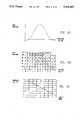
- FIG. 6Ais a representation of a bar code symbol with two typical parallel scan lines, which may be utilized in conjunction with the embodiments of the present invention.
- FIG. 6Billustrates the reflectance signals from the two parallel scan lines of FIG. 6A.
- FIG. 6Crepresents the signal differences between successive data points along each of the two respective scan lines of FIG. 6B utilized in the present invention.
- FIG. 6Dillustrates the products of the signal differences for each of the respective data points for the signal differences shown in FIG. 6C, and the sum total of all products of the signal differences along two parallel scan lines utilized in conjunction with the present invention.
- FIG. 7Ais a representation of a black to white transition with two typical parallel scan lines, which may be distinguished from a bar code symbol in conjunction with the present invention.
- FIG. 7Billustrates the reflectance signals from the two parallel scan lines of FIG. 7A.
- FIG. 7Crepresents the signal differences between successive data points along each of the two respective scan lines of FIG. 7B utilized in the present invention.
- FIG. 7Dillustrates the products of the signal differences for each of the respective data points for the signal differences shown in FIG. 7C, and the sum total of all products of the signal differences along two parallel scan lines utilized in the present invention.
- FIG. 8Ais an image of a bar code symbol at an angle to the direction of scan with a portion of the scanned area indicated.
- FIG. 8Billustrates the reflectance signal from one scan line of the scanned area indicated in FIG. 8A.
- FIG. 8Cillustrates the scan line of FIG. 8B after processing by interpolation.
- FIG. 8Dshows one interpolated scan line and another interpolated scan line, four scan lines apart.
- FIG. 8Eshows eight interpolated scan lines which have been shifted respectively into alignment.
- FIG. 8Fshows the average of the eight interpolated and shifted scan lines of FIG. 8E.
- FIG. 8Gis a binary signal representation of the waveform of FIG. 8F using the overall signal average as the binary threshold value.
- FIG. 9Ais the cross-correlation function of the interpolated first and second scan lines of the portion of the scanned area in FIG. 8A.
- FIG. 9Bis a family of cross-correlation curves, each resulting from cross-correlating the first interpolated scan line with successive interpolated scan lines of the portion of the scanned area in FIG. 8A.
- FIG. 9Cshows the peak values of the cross-correlation function for each interpolated scan line compared to the first interpolated scan line for the portion of the scanned area indicated in FIG. 8A.
- FIG. 10is an illustration of a bar code symbol, depicting the manner in which overlapping partial scans are concatenated to form a complete scan.
- FIG. 1A brief overview of a bar code reader in accordance with the present invention is shown in FIG. 1.
- An image acquisition system 14which includes the necessary optical and photosensitive elements, captures an image of the reader's field of view, which captured image may contain a bar code label 12.
- image acquisition 14 and bar code image location and orientation 16comprise the portion of the present bar code reader which serves to generally locate a bar code within a field of view.
- means 18are provided for determining the fine orientation of the bar code. Having located the bar code and determining its fine orientation, means 20 for filtering the bar code, are provided. Thereafter, bar code scanning 22 is performed. The operation of determining the fine orientation 18, bar code filtering 20, and bar code scanning 22, together comprise the portion of the present bar code reader which serves to "scan" a bar code once having been located within a field of view.
- a decoder 23well known to those skilled in the art, provides the decoded bar code label output 24.
- the operation of "scanning a bar code”, as used in the prior art,relates to sweeping an illuminated spot across a bar code.
- the operation of "scanning a bar code”means to extract from image memory storage, sequential values derived from said image memory storage corresponding to reflectivities along a sweep traversing the bar code.
- FIG. 2A preferred hardware embodiment of the present invention is shown in FIG. 2.
- An optical system 26is coupled to an image sensor array 28.
- the output of the image sensor array 28is converted from analog to digital in A/D converter 30, and stored in a first memory 32.
- the first memory 32is preferably a dynamic random access memory (DRAM).
- a controller 34which may be an application specific integrated circuit (ASIC) controls the image acquisition system so as to capture and digitize an image and store it in DRAM 32.
- ASIC controller 34also performs several other processing tasks under the control of a digital signal processor 38.
- Digital signal processor 38is typically a high speed microprocessor such as the ADSP-2101 available from Analog Devices, Norwood, Mass.
- the memory space for digital signal processor 38is both ROM for program storage and a static random access memory 42 (SRAM) for image processing storage. Portions of the stored image memory in DRAM 32 are transferable to SRAM 42 under the control of ASIC controller 34. Finally, an input terminal 40 is coupled to the input of digital signal processor 38, and output terminal 44 is coupled to a decoder 23 which is coupled to the output of digital signal processor 38.
- SRAMstatic random access memory
- a bar code readis initiated by an input signal on terminal 40 to digital signal processor 38.
- ASIC controller 34acquires an image for storage in DRAM memory 32.
- ASIC controller 34processes the stored image in DRAM 32 so as to determine the potential location or locations which are likely to contain a bar code symbol.
- the image stored in DRAM 32is divided into smaller areas, or cells, and a location score is assigned to each cell. The higher the location score for a given cell, the more likely is the cell to contain at least a partial bar code symbol.
- digital signal processor 38examines the resulting scores and commands the ASIC controller 34 to transfer those image areas of interest from DRAM 32 to SRAM 42.
- Digital signal processor 38thereafter processes the partial image in SRAM 42 to determine the orientation of the stored bar code image, to filter the oriented bar code image along a direction perpendicular to the determined orientation, and to scan the oriented and filtered bar code image. After all areas of interest have been transferred from DRAM 32 to SRAM 42 and processed by digital signal processor 38, a complete bar code output scan is provided to decoder 23 which provides a decoded bar code label output at terminal 44.
- digital signal processor 38may command the optical system 26, the image sensor array 28 and the A/D converter 30 to acquire another image in DRAM 32 for processing.
- the process of acquiring and processing imagesmay continue until a bar code symbol is successfully scanned.
- the organization of the stored DRAM image area 48is shown in FIG. 3.
- the image sensor array 28(FIG. 2) has 768 pixels in the horizontal direction and 576 pixels in the vertical direction.
- a suitable image sensor for use with the present inventionis the MOS image sensor array 98268 available from Hitachi Corporation.
- the image area 48is conceptually divided into cells, such as cell 49. Specifically, the image area 48 is divided into 24 cells in the horizontal direction and 72 cells in the vertical direction, with each cell being 8 by 32 pixels. That is, each cell has 8 scan lines, with each scan line having 32 pixels.
- the image area 48is divided into cells in each of four directions. That is, image area 48 is divided into horizontal cells such as cell 50. However, image area 48 is also divided vertical cells such as cell 52. Similarly, image area 48 is divided into cells along a rising diagonal i.e. 45 degrees such as cell 56. Finally, image area 48 is divided into cells along a falling diagonal i.e. 135 degrees such as cell 54. Using four directions of scan lines permits the location process to also determine the coarse orientation of the located bar code image in the same operation.
- FIG. 3Ashows a bar code symbol somewhere within the field of view of image area 48 and oriented 14 degrees off the vertical direction.
- a typical vertical cell 52is shown superimposed over a portion of bar code symbol 58.
- the portion of the program of the ASIC controller 34(FIG. 2) for determining the location or locations likely to contain a bar code symbol is shown in the flow chart of FIG. 4.
- the processuses two scan lines, i.e. scan line A, and scan line B.
- scan line Ais the first of the eight scan lines of a given cell
- scan line Bis the fifth scan line of a given cell.
- the approximate derivative of scan line A, and the approximate derivative of scan line Bare calculated at step 60.
- a derivativeis approximated by taking the difference between any two consecutive pixels.
- every other pixelis used in the calculation, i.e. instead of using all 32 pixels across a scan line of a given cell, every other pixel i.e. 16 pixels are used to approximate a derivative.
- the point by point product of both derivativesis calculated at step 62. Thereafter, the sum of the products of derivatives is accumulated at step 64. This process of accumulating the sum of the product of derivatives continues until all the points of scan lines A and B are completed for this cell at step 66. At this point, the accumulated product of derivatives constitutes the location score for this particular cell. The location score is then stored in SRAM at step 68. The program increments to the next cell in the image area at step 70. The process of computing location scores continues from cell to cell until the end of the image area is detected at step 72, and the program is exited.
- FIGS. 6A through 6DThe process of computing a location score for a cell is illustrated in FIGS. 6A through 6D.
- scan line A and scan line Bare shown at a slight angle across a portion of a bar code symbol.
- FIG. 6Bshows the reflectance signals at approximately 1.5 pixels per narrow bar for both scan line A and scan line B. The data points are simply connected by straight lines.
- FIG. 6Cshows the result of taking the difference between successive data points along scan line A and successive data points along scan line B to produce an approximate derivative shown as delta scan line A and delta scan line B, respectively.
- FIG. 6Dshows the product of each data point along delta scan line A and the corresponding data point along delta scan line B.
- 6D for each data pointis the product of the approximate derivatives of each respective data point of scan line A and scan line B. Adding up the sum of the derivatives produces a location score equal to 810, which is a relatively high score because scan line A and scan line B are directly through a bar code symbol.
- FIGS. 7A through 7Dindicate the corresponding location score for a simple black to white transition.
- FIG. 7Ashows an image with a black to white transition with two scan lines, scan line A and scan line B therethrough.
- FIG. 7Bshows the reflectance signals for scan line A and scan line B.
- FIG. 7Cshows the approximate derivative or delta scan line A and delta scan line B, while FIG. 7D shows the sum of the derivatives for each point on both scan line A and scan line B.
- the resulting location score of 57 from FIG. 7D for the image in FIG. 7Ais considerably less than the location score of 810 for the bar code in FIG. 6A.
- the program flow chart for the digital signal processor 38 in FIG. 2,is shown in FIGS. 5A and 5B. Responsive to an input signal on terminal 40 of FIG. 2, to initiate a bar code read, the digital signal processor 38 enters the program as shown in the flow chart of FIG. 5A.
- the first step 74is to command the ASIC controller to capture the image area to DRAM. Once the image area is captured, the next step 76 is to command the ASIC controller to perform the bar code location algorithm (in accordance with the flow chart of FIG. 4, discussed above) for one direction i.e. the horizontal direction. As the location algorithm is performed for all cells in the horizontal direction in image area 48, the ASIC controller stores the results in SRAM. Each cell score, is an indication of the likelihood of bar code activity.
- the complete set of scores for a given directionforms a map of the likely regions of bar code activity. This process is repeated for all four directions i.e. location scores for a vertical scan are computed and stored in SRAM thorough program loop 80; location scores for a rising diagonal scan, i.e. a 45 degree scan, are computed and stored in SRAM thorough program loop 82; and location scores for a falling diagonal scan, i.e. a 135 degree scan, are computed and stored in SRAM thorough program loop 84.
- the digital signal processor programdetermines whether or not bar code activity is present at step 78. For this purpose, a simple threshold may be utilized, examining all location scores that exceed a given threshold. If no score exceeds a given threshold, then no bar code activity is found, and the program repeats starting from step 74 in which the ASIC controller captures a new image area to DRAM. However, if bar code activity is detected at step 78, the subsequent digital signal processor program, in accordance with the flow chart of FIG. 5B, proceeds to orient, filter, and scan the located bar code.
- the first stepis to determine from the location scores stored in SRAM, the center of the region of bar code activity, and the likely horizontal and vertical extent of such activity, at step 86.
- the approximate center and extent of bar code activitymay be determined by region growing applied to the cell activity score map.
- Region growingis a common image processing task to identify a particular region of an overall image which particular region possesses a specific characteristic, in this case, large values. Region growing is a technique well known to those skilled in the art of image processing, and is disclosed in "MATRIX STRUCTURED IMAGE PROCESSING" by Dougherty and Giardina, published 1987 by Prentice-Hall Inc, Englewood Cliffs, N.J. 07632.
- the digital signal processorcommands the ASIC controller to transfer the image area containing bar code activity from DRAM to SRAM at step 88.
- SRAM memory spaceis generally smaller than DRAM memory space, and typically represents a few percent of the total image area stored in DRAM.
- SRAMis generally faster than DRAM, the use of a relatively smaller SRAM is more economical since the cost of SRAM is typically more than DRAM.
- the area of the image stored in SRAMmay or may not be related to the size of the cell areas from the DRAM image memory. Due to the smaller size of the SRAM, the latter may hold only a portion of a bar code, in which case processing steps are repeated for partial scans and the partial scans later combined to form a complete scan.
- the digital signal processorinterpolates each of the scan lines of data for a given image area of interest at step 90.
- the process of interpolationis well known to those skilled in the art of digital signal processing, and is described by Peled and Liu in "DIGITAL SIGNAL PROCESSING theory, design, and implementation", published 1976 by John Wiley and Sons. Interpolation increases the effective sampling rate of the scan line data by fitting the best curve to the data with frequencies below the Nyquist limit.
- the bar code imageis initially sampled at about 1.5 pixels per narrow bar. To create a smoother curve, the signal is upsampled by four times. In simple terms, rather than connecting the data points by straight lines, additional data points are added between the actual data points to form a smoother curve.
- the first scan line of a given cellis cross-correlated with successive adjacent interpolated scan line data as indicated in step 92.
- Cross-correlationprovides a measure of the similarity, or match, between two curves. Techniques for cross-correlating two signals are well known to those skilled in the art, and a discussion of cross-correlation may be found in "DIGITAL PROCESSING OF SPEECH SIGNALS" by Rabiner and Schafer published 1978 by Prentiss Hall, Englewood Cliffs, N.J. 07632.
- Successive cross-correlation between adjacent interpolated scan line dataprovides a means to determine the fine orientation of the bar code symbol also at step 92.
- the detected fine orientation of the bar codeis derived from the difference between the average peaks of successive cross-correlations between adjacent interpolated scan lines.
- the position of the peak of the cross-correlation function of two scan linesrepresents the amount one scan line of data must be shifted in order to provide the best alignment with the other scan line of data. Calculation of the actual angle of the bars is discussed below in relation to FIG. 9A through FIG. 9C.
- each interpolated scan line datais shifted into alignment at step 94.
- the average of all scan linesis computed.
- the bar code symbolmay be decoded into a partial bar code scan at step 94.
- the partial bar code scanis stored at step 94, and the next stored region of interest is determined at step 96. That is, the next area of interest which is likely to contain a bar code image is then transferred from DRAM to SRAM at step 88. The process of interpolation and cross-correlation is repeated until another partial bar code scan, representing an adjacent image area of interest, is stored.
- the partial scansare concatenated, or connected to form a complete scan at step 9B.
- the output scanis forwarded to a decoder, known to those skilled in the art, for converting the complete concatenated bar code scan into a sequence of alphanumeric characters which represent the content of the bar code.
- FIGS. 8A through 8G and FIGS. 9A through 9Cillustrate the processes for detecting fine orientation, filtering and scanning of a bar code that has been located in a given cell.
- FIG. 8Aillustrates a vertical cell 52 consisting of 8 scan lines superimposed over a portion of a bar code label 58. The poor appearance, or spottiness of the bars is actually representative of the condition of many printed bar code labels encountered in practice.
- FIG. 8Bshows the 32 pixels of the first scan line of cell 52 connected by straight lines.
- FIG. 8Cshows the same 32 data points after interpolation, or upsampling by four times.
- FIG. 8Dshows one upsampled scan line, and another upsampled scan line which is 4 scan lines away. It is evident there is an offset between the two waveforms. This offset is indicative of the orientation offset of the bars.
- FIGS. 9A through 9Cillustrate the process of determining the fine orientation of the bar code symbol.
- FIG. 9Ashows the cross-correlation function of the first and second scan lines of the sampled signal Note that the peak is at a lag of about minus one. This means that over a distance from one scan line to the next, the waveform is shifted one upsampled pixel, or one fourth of an original pixel. This yields a bar code slope of one fourth, or 0.25, which corresponds well with the measured slope of about 14 degrees, since the arctangent of 0.25 equals 14.036 degrees.
- FIG. 9Bshows a family of cross-correlation curves. Each curve is the result of cross-correlating the first scan line with the scan line successively further away. Note that the peaks step over extremely consistently by one for each curve. By using interpolation, it is possible to find the position of a peak in the cross-correlation function to fractional pixel accuracy.
- FIG. 9Cis a plot of the cross-correlation function for each scan line compared to the first scan line of the given area of interest. Note that the calculated peak values lie almost perfectly along a straight line, the slope of which represents the fine orientation angle of the bar code symbol. In general, not all of the peak values may lie on a straight line, in which case the average slope may be taken to represent the fine orientation of the bar code symbol.
- each of the interpolated scan line datais shifted into alignment as shown in FIG. 8E, and the average value taken as shown in FIG. 8F.
- Taking the average of corresponding sample points from the shifted lines of interpolated scan line dataprovides a simple approach to bar code filtering. Averaging effectively filters perpendicular to the orientation of the bar code.
- the median value of each data pointcould be used to reduce the effect of occasional missing pieces of the bar code label. That is, a white spot on a black bar effects the median data value less than the average data value.
- Another approachis to take a weighted average based on cross-correlation scores to provide better rejection of poorly correlated scan line data. In the latter case, those interpolated scan lines that correlate well with each other would count more heavily in the average, while those interpolated scan lines which cross-correlate poorly would weight the average correspondingly less.
- shiftingscan line data includes both actual shifting of scan line data within the image memory as well as virtual shifting of scan line data by the use of an offset vector to be added to the location of sequential values extracted from said memory.
- bar code fine orientationmay be achieved by cross-correlation of selected pairs of scan line data alone, without interpolation of scan line data if there are sufficient data points, or pixels per narrow bar. Otherwise, interpolation is used to generate the additional data points for the cross-correlation to be meaningful. Finally, in shifting scan lines into alignment, all successive scan line data may be correlated to a single reference line, or in the alternative, successive scan line data may be correlated in line pairs and not referenced to a single scan line.
- the aggregate waveform in FIG. 8Fis then converted to a binary value waveform as shown in FIG. 8G using the overall signal average as the binary threshold.
- the zero level of the waveform in FIG. 8Gcorresponds to the black level of the bar code in FIG. 8A, while the one level corresponds to the white level.
- FIG. 10shows how successive partial scans 100, 102 and 104 may be concatenated to form a complete scan of bar code 58.
- the partial scansoverlap each other so that no bar code data is lost.
- the successive partial scansare taken in steps along an angle corresponding to the measured fine orientation of the bars. That is, since the fine orientation of the bars is 14 degrees, a staircase of partial scans along a 14 degree angle off the vertical, is constructed in order to acquire partial scans which can be concatenated into a complete scan of the bar code label.
- a bar code readerhas been disclosed which is capable of reading a bar code symbol contained anywhere within the field of view of an image area in an omnidirectional manner.
- an area image capture deviceit will be appreciated that a linear image capture device as may be used with a moving conveyor belt, may also be used.
Landscapes
- Physics & Mathematics (AREA)
- Engineering & Computer Science (AREA)
- Electromagnetism (AREA)
- Artificial Intelligence (AREA)
- Toxicology (AREA)
- General Health & Medical Sciences (AREA)
- Health & Medical Sciences (AREA)
- Computer Vision & Pattern Recognition (AREA)
- General Physics & Mathematics (AREA)
- Theoretical Computer Science (AREA)
- Quality & Reliability (AREA)
- Image Analysis (AREA)
- Image Processing (AREA)
Abstract
Description
Claims (58)
Priority Applications (4)
| Application Number | Priority Date | Filing Date | Title |
|---|---|---|---|
| US07/501,259US5155343A (en) | 1990-03-28 | 1990-03-28 | Omnidirectional bar code reader with method and apparatus for detecting and scanning a bar code symbol |
| JP3064909AJP2927562B2 (en) | 1990-03-28 | 1991-03-28 | Barcode symbol detection and scanning method and apparatus in omnidirectional barcode reader |
| DE69131216TDE69131216T2 (en) | 1990-03-28 | 1991-03-28 | Determining the position of bar codes |
| EP91302787AEP0449645B1 (en) | 1990-03-28 | 1991-03-28 | Locating bar code symbols |
Applications Claiming Priority (1)
| Application Number | Priority Date | Filing Date | Title |
|---|---|---|---|
| US07/501,259US5155343A (en) | 1990-03-28 | 1990-03-28 | Omnidirectional bar code reader with method and apparatus for detecting and scanning a bar code symbol |
Publications (1)
| Publication Number | Publication Date |
|---|---|
| US5155343Atrue US5155343A (en) | 1992-10-13 |
Family
ID=23992790
Family Applications (1)
| Application Number | Title | Priority Date | Filing Date |
|---|---|---|---|
| US07/501,259Expired - Fee RelatedUS5155343A (en) | 1990-03-28 | 1990-03-28 | Omnidirectional bar code reader with method and apparatus for detecting and scanning a bar code symbol |
Country Status (4)
| Country | Link |
|---|---|
| US (1) | US5155343A (en) |
| EP (1) | EP0449645B1 (en) |
| JP (1) | JP2927562B2 (en) |
| DE (1) | DE69131216T2 (en) |
Cited By (121)
| Publication number | Priority date | Publication date | Assignee | Title |
|---|---|---|---|---|
| US5276315A (en)* | 1992-05-14 | 1994-01-04 | United Parcel Service Of America, Inc. | Method and apparatus for processing low resolution images of degraded bar code symbols |
| US5278398A (en)* | 1990-01-05 | 1994-01-11 | Symbol Technologies, Inc. | Decoding bar code symbols by determining the best alignment of partial scans |
| US5286960A (en)* | 1991-11-04 | 1994-02-15 | Welch Allyn, Inc. | Method of programmable digitization and bar code scanning apparatus employing same |
| US5329105A (en)* | 1992-08-10 | 1994-07-12 | United Parcel Service Of America, Inc. | Method and apparatus for determining the width of elements of bar code symbols |
| US5343028A (en)* | 1992-08-10 | 1994-08-30 | United Parcel Service Of America, Inc. | Method and apparatus for detecting and decoding bar code symbols using two-dimensional digital pixel images |
| US5352878A (en)* | 1993-01-29 | 1994-10-04 | United Parcel Service Of America, Inc. | Method and apparatus for decoding bar code symbols using independent bar and space analysis |
| US5357093A (en)* | 1993-02-01 | 1994-10-18 | Storage Technology Corporation | System and method for converting bar code scan line data into machine-readable code |
| US5384451A (en)* | 1993-01-29 | 1995-01-24 | United Parcel Service Of America, Inc. | Method and apparatus for decoding bar code symbols using composite signals |
| US5404003A (en)* | 1993-02-01 | 1995-04-04 | United Parcel Service Of America, Inc. | Method and apparatus for decoding bar code symbols using byte-based searching |
| US5412196A (en)* | 1994-04-01 | 1995-05-02 | United Parcel Service Of America, Inc. | Method and apparatus for decoding bar code images using multi-order feature vectors |
| US5412197A (en)* | 1993-01-29 | 1995-05-02 | United Parcel Service Of America, Inc. | Method and apparatus for decoding bar code symbols using gradient signals |
| US5418862A (en)* | 1992-08-10 | 1995-05-23 | United Parcel Service Of America | Method and apparatus for detecting artifact corners in two-dimensional images |
| US5422470A (en)* | 1992-08-31 | 1995-06-06 | Olympus Optical Co., Ltd. | Symbol information reading apparatus |
| US5428211A (en)* | 1994-05-02 | 1995-06-27 | United Parcel Service Of America Inc. | Postnet bar code decoder |
| US5430283A (en)* | 1992-09-10 | 1995-07-04 | Olympus Optical Co., Ltd. | Bar-code symbol reading apparatus |
| US5438636A (en)* | 1992-05-14 | 1995-08-01 | United Parcel Service Of America, Inc. | Apparatus for simultaneously convolving multiple digital binary images using a single convolver with a binary mask to determine pixel densities |
| US5438188A (en)* | 1994-04-01 | 1995-08-01 | United Parcel Service Of America, Inc. | Method and apparatus for decoding bar code images using information from previous scan lines |
| US5446271A (en)* | 1993-08-06 | 1995-08-29 | Spectra-Physics Scanning Systems, Inc. | Omnidirectional scanning method and apparatus |
| US5457308A (en)* | 1993-09-14 | 1995-10-10 | Symbol Technologies, Inc. | Bar code scan stitching |
| WO1995030184A1 (en)* | 1994-04-29 | 1995-11-09 | Tps Electronics | Pcmcia interface card for input devices such as barcode scanning engines |
| US5468945A (en)* | 1994-02-25 | 1995-11-21 | Intermec Corporation | Method and apparatus for locating and decoding a postnet forwarding bar code in a field of postnet bar codes |
| US5481097A (en)* | 1993-01-25 | 1996-01-02 | Psc Inc. | Apparatus and method for decoding bar codes |
| US5487115A (en)* | 1992-05-14 | 1996-01-23 | United Parcel Service | Method and apparatus for determining the fine angular orientation of bar code symbols in two-dimensional CCD images |
| US5489769A (en)* | 1992-05-26 | 1996-02-06 | Olympus Optical Co., Ltd. | Symbol information reading apparatus |
| US5495097A (en)* | 1993-09-14 | 1996-02-27 | Symbol Technologies, Inc. | Plurality of scan units with scan stitching |
| US5504367A (en)* | 1994-03-21 | 1996-04-02 | Intermec Corporation | Symbology reader illumination system |
| US5515447A (en)* | 1994-06-07 | 1996-05-07 | United Parcel Service Of America, Inc. | Method and apparatus for locating an acquisition target in two-dimensional images by detecting symmetry in two different directions |
| US5521368A (en)* | 1993-09-22 | 1996-05-28 | Olympus Optical Co., Ltd. | Barcode symbol reading system having function for detecting and correcting inclination of barcode symbol |
| US5524068A (en)* | 1992-08-21 | 1996-06-04 | United Parcel Service Of America, Inc. | Method and apparatus for finding areas of interest in images |
| US5541419A (en)* | 1994-03-21 | 1996-07-30 | Intermec Corporation | Symbology reader wth reduced specular reflection |
| US5550364A (en)* | 1994-03-21 | 1996-08-27 | Intermec Corporation | Method and apparatus for spotter beam formation using a partitioned optical element |
| US5553084A (en)* | 1995-01-06 | 1996-09-03 | Intermec Corporation | Error correction enhancement for code one and other machine-readable symbologies |
| US5557091A (en)* | 1994-04-15 | 1996-09-17 | Krummel; Larry | Method and system for bar code image processing |
| US5591954A (en)* | 1995-02-23 | 1997-01-07 | At&T Global Information Solutions Company | Apparatus and method for equalizing the signal strengths of different scan lines |
| US5598007A (en)* | 1994-03-21 | 1997-01-28 | Intermec Corporation | Symbology reader with fixed focus spotter beam |
| US5614704A (en)* | 1994-03-16 | 1997-03-25 | Asahi Kogaku Kogyo Kabushiki Kaisha | Encoded symbol reader with image reversal function |
| US5642442A (en)* | 1995-04-10 | 1997-06-24 | United Parcel Services Of America, Inc. | Method for locating the position and orientation of a fiduciary mark |
| US5698833A (en)* | 1996-04-15 | 1997-12-16 | United Parcel Service Of America, Inc. | Omnidirectional barcode locator |
| US5742041A (en)* | 1996-05-29 | 1998-04-21 | Intermec Corporation | Method and apparatus for locating and decoding machine-readable symbols, including data matrix symbols |
| US5748804A (en)* | 1992-05-14 | 1998-05-05 | United Parcel Service Of America, Inc. | Method and apparatus for processing images with symbols with dense edges |
| US5770847A (en)* | 1994-12-23 | 1998-06-23 | Spectra-Physics Scanning Systems, Inc. | Bar code reader with multi-focus lens |
| US5777309A (en)* | 1995-10-30 | 1998-07-07 | Intermec Corporation | Method and apparatus for locating and decoding machine-readable symbols |
| US5811776A (en)* | 1996-02-26 | 1998-09-22 | Intermec Corporation | Method and apparatus for accurately locating data regions in stored images of symbols |
| US5814803A (en)* | 1994-12-23 | 1998-09-29 | Spectra-Physics Scanning Systems, Inc. | Image reader with multi-focus lens |
| US5821519A (en)* | 1993-09-14 | 1998-10-13 | Symbol Technologies, Inc. | Bar code scan stitching |
| US5825006A (en)* | 1994-03-04 | 1998-10-20 | Welch Allyn, Inc. | Optical reader having improved autodiscrimination features |
| US5831674A (en)* | 1994-06-10 | 1998-11-03 | Metanetics Corporation | Oblique access to image data for reading bar codes |
| US5854478A (en)* | 1996-10-11 | 1998-12-29 | Intermec Ip Corp. | Method and apparatus for reading machine-readable symbols having surface or optical distortions |
| US5862267A (en)* | 1995-12-11 | 1999-01-19 | Intermec Ip Corp. | Method and apparatus for locating data regions in stored images of symbols |
| US5867594A (en)* | 1994-06-15 | 1999-02-02 | Metanetics Corporation | Recognizing dataforms in image areas |
| US5936224A (en)* | 1996-12-11 | 1999-08-10 | Intermec Ip Corporation | Method and apparatus for reading machine-readable symbols by employing a combination of multiple operators and/or processors |
| US5988506A (en)* | 1996-07-16 | 1999-11-23 | Galore Scantec Ltd. | System and method for reading and decoding two dimensional codes of high density |
| US6000618A (en)* | 1996-12-30 | 1999-12-14 | Datalogic S.P.A. | Method of reading an object-applied bar code |
| US6012640A (en)* | 1997-07-08 | 2000-01-11 | Intermec Ip Corporation | Rule based and fuzzy logic method and apparatus for processing reflectance signals from machine-readable symbols or images |
| US6015088A (en)* | 1996-11-05 | 2000-01-18 | Welch Allyn, Inc. | Decoding of real time video imaging |
| US6016960A (en)* | 1997-07-08 | 2000-01-25 | Intermec Ip Corporation | Rule based method and apparatus for processing reflectance signals from machine-readable symbols or images |
| US6094509A (en)* | 1994-06-07 | 2000-07-25 | United Parcel Service Of America, Inc. | Method and apparatus for decoding two-dimensional symbols in the spatial domain |
| US6097839A (en)* | 1997-03-10 | 2000-08-01 | Intermec Ip Corporation | Method and apparatus for automatic discriminating and locating patterns such as finder patterns, or portions thereof, in machine-readable symbols |
| US6095420A (en)* | 1995-12-25 | 2000-08-01 | Fujitsu Limited | Method of decoding bar codes and bar code reader |
| US6123261A (en)* | 1997-05-05 | 2000-09-26 | Roustaei; Alexander R. | Optical scanner and image reader for reading images and decoding optical information including one and two dimensional symbologies at variable depth of field |
| US6128414A (en)* | 1997-09-29 | 2000-10-03 | Intermec Ip Corporation | Non-linear image processing and automatic discriminating method and apparatus for images such as images of machine-readable symbols |
| US6145745A (en)* | 1997-04-22 | 2000-11-14 | Sick Ag | Method and apparatus for the reading of a bar code |
| US6236735B1 (en) | 1995-04-10 | 2001-05-22 | United Parcel Service Of America, Inc. | Two camera system for locating and storing indicia on conveyed items |
| US6328214B1 (en)* | 1999-01-22 | 2001-12-11 | Intermec Ip Corporation | Opto-electronic device for acquisition of images of codes in one and two dimensions |
| US6343740B1 (en)* | 1994-06-10 | 2002-02-05 | Paul P. Ju | Oblique access to image data for reading apparatus |
| US20020136469A1 (en)* | 2001-03-23 | 2002-09-26 | Fujitsu Limited | Image processing apparatus, image processing method and computer-readable medium on which image processing program is recorded |
| US20030085282A1 (en)* | 1996-09-03 | 2003-05-08 | Welch Allyn Data Collection, Inc. | Scanning and decoding control for an optical reader |
| US20030121980A1 (en)* | 1995-01-03 | 2003-07-03 | Lemelson Jerome H. | Method and apparatus for encoding and decoding bar codes with primary and secondary information and method of using such bar codes |
| US6616039B1 (en)* | 1998-12-22 | 2003-09-09 | Datalogic S.P.A. | Method for automatic regulation of the characteristics of an optical code reading system |
| US20030181168A1 (en)* | 1997-08-05 | 2003-09-25 | Allan Herrod | Terminal with optical reader for locating products in a retail establishment |
| US20040004128A1 (en)* | 1996-09-03 | 2004-01-08 | Hand Held Products, Inc. | Optical reader system comprising digital conversion circuit |
| US6681994B1 (en) | 1988-08-31 | 2004-01-27 | Intermec Ip Corp. | Method and apparatus for optically reading information |
| US6708884B1 (en)* | 2002-06-25 | 2004-03-23 | The United States Of America As Represented By The Secretary Of The Army | Method and apparatus for rapid and precision detection of omnidirectional postnet barcode location |
| US20040164155A1 (en)* | 2003-02-21 | 2004-08-26 | Fujitsu Limited | Bar-code reader and method of reading bar code |
| US20040223663A1 (en)* | 2003-05-05 | 2004-11-11 | International Business Machines Corporation | Apparatus and method for determining whether machine readable information on an item matches the item |
| US6889903B1 (en) | 1988-08-31 | 2005-05-10 | Intermec Ip Corp. | Method and apparatus for optically reading information |
| US20050145698A1 (en)* | 2003-12-02 | 2005-07-07 | Havens William H. | Method and apparatus for reading under sampled bar code symbols |
| US6941026B1 (en) | 2000-06-13 | 2005-09-06 | Cognex Corporation | Method and apparatus using intensity gradients for visual identification of 2D matrix symbols |
| US20050258249A1 (en)* | 2004-04-29 | 2005-11-24 | Giebel James R | Imaging pixel array with programmable pixel aspect ratio for an optical code reader |
| US20060027657A1 (en)* | 2004-08-04 | 2006-02-09 | Laurens Ninnink | Method and apparatus for high resolution decoding of encoded symbols |
| US20060043186A1 (en)* | 2004-08-30 | 2006-03-02 | Nadabar Sateesha G | Methods and apparatus for reading bar code identifications |
| US20060043191A1 (en)* | 2004-08-31 | 2006-03-02 | Mehul Patel | System and method for aiming an optical code scanning device |
| US20060081712A1 (en)* | 2004-10-18 | 2006-04-20 | Psc Scanning, Inc. | System and method of optical reading employing virtual scan lines |
| US20060109526A1 (en)* | 2004-11-24 | 2006-05-25 | Zhang Daoxian H | Case divider for organizing patient films |
| US20060163355A1 (en)* | 2005-01-26 | 2006-07-27 | Psc Scanning, Inc. | Data reader and methods for imaging targets subject to specular reflection |
| US7181066B1 (en) | 2002-12-26 | 2007-02-20 | Cognex Technology And Investment Corporation | Method for locating bar codes and symbols in an image |
| US20070170259A1 (en)* | 2006-01-25 | 2007-07-26 | Laurens Nunnink | Method and apparatus for providing a focus indication for optical imaging of visual codes |
| US20070262147A1 (en)* | 2006-05-10 | 2007-11-15 | Mckesson Automation Inc. | System, method and corresponding apparatus for storing, retrieving and delivering unit dose blisters |
| US20080004822A1 (en)* | 2006-06-29 | 2008-01-03 | Sateesha Nadabar | Method and Apparatus for Verifying Two Dimensional Mark Quality |
| US20080023561A1 (en)* | 1992-03-12 | 2008-01-31 | Intermec Ip Corp. | Reader for decoding two-dimensional optically readable information |
| US20080318191A1 (en)* | 2004-03-25 | 2008-12-25 | Mcadams John B | Braille type device, system, and method |
| US20090067731A1 (en)* | 2007-09-07 | 2009-03-12 | Datalogic Scanning, Inc. | Compensated virtual scan lines |
| US20090166424A1 (en)* | 2007-12-28 | 2009-07-02 | Gerst Carl W | Method And Apparatus Using Aiming Pattern For Machine Vision Training |
| US20100010660A1 (en)* | 2005-04-11 | 2010-01-14 | The Boeing Company | Method of manufacturing a product using scan targets |
| US20100078477A1 (en)* | 2008-09-30 | 2010-04-01 | Hand Held Products, Inc. | Method and apparatus for operating indicia reading terminal including parameter determination |
| US20100176319A1 (en)* | 2009-01-12 | 2010-07-15 | Cognex Corporation | Modular focus system for image based code readers (as amended) |
| US20100193588A1 (en)* | 2009-02-04 | 2010-08-05 | Datalogic Scanning, Inc. | Systems and methods for selectively masking a scan volume of a data reader |
| US20110073657A1 (en)* | 2009-09-30 | 2011-03-31 | Miroslav Trajkovic | Method and apparatus for detecting a barcode |
| US7963448B2 (en) | 2004-12-22 | 2011-06-21 | Cognex Technology And Investment Corporation | Hand held machine vision method and apparatus |
| US8009913B2 (en) | 2007-05-29 | 2011-08-30 | Mckesson Automation, Inc. | System, method, apparatus and computer program product for capturing human-readable text displayed on a unit dose package |
| US8169478B2 (en) | 2006-12-14 | 2012-05-01 | Cognex Corporation | Method and apparatus for calibrating a mark verifier |
| US8326037B1 (en)* | 2005-11-23 | 2012-12-04 | Matrox Electronic Systems, Ltd. | Methods and apparatus for locating an object in an image |
| US8587595B2 (en) | 2009-10-01 | 2013-11-19 | Hand Held Products, Inc. | Low power multi-core decoder system and method |
| US8628015B2 (en) | 2008-10-31 | 2014-01-14 | Hand Held Products, Inc. | Indicia reading terminal including frame quality evaluation processing |
| US8646689B2 (en) | 2007-12-28 | 2014-02-11 | Cognex Corporation | Deformable light pattern for machine vision system |
| US8929641B2 (en) | 2009-03-17 | 2015-01-06 | Aesynt Incorporated | System and method for determining the orientation of a unit dose package |
| US20150156365A1 (en)* | 2013-12-04 | 2015-06-04 | University Of Rochester | Image Based Correction of Distortion from a Scanner |
| US20150169925A1 (en)* | 2012-06-27 | 2015-06-18 | Honeywell International Inc. | Encoded information reading terminal with micro-projector |
| US9122952B2 (en) | 2011-12-23 | 2015-09-01 | Cognex Corporation | Methods and apparatus for one-dimensional signal extraction |
| US9495571B1 (en) | 2015-09-30 | 2016-11-15 | Datalogic Automation, Inc. | Two-dimensional representation of linear barcode derived from laser barcode scanner scanline data |
| US9519817B1 (en)* | 2016-08-18 | 2016-12-13 | Benq Co., Ltd. | Method for digitizing barcode image by using dynamic threshold |
| US9552506B1 (en) | 2004-12-23 | 2017-01-24 | Cognex Technology And Investment Llc | Method and apparatus for industrial identification mark verification |
| US9746636B2 (en) | 2012-10-19 | 2017-08-29 | Cognex Corporation | Carrier frame and circuit board for an electronic device |
| US10067312B2 (en) | 2011-11-22 | 2018-09-04 | Cognex Corporation | Vision system camera with mount for multiple lens types |
| US10498934B2 (en) | 2011-11-22 | 2019-12-03 | Cognex Corporation | Camera system with exchangeable illumination assembly |
| US10592715B2 (en) | 2007-11-13 | 2020-03-17 | Cognex Corporation | System and method for reading patterns using multiple image frames |
| CN113551578A (en)* | 2021-08-01 | 2021-10-26 | 李里 | Bar-shaped displacement code, bar-shaped displacement code ruler and displacement detection device |
| US11317050B2 (en) | 2005-03-11 | 2022-04-26 | Hand Held Products, Inc. | Image reader comprising CMOS based image sensor array |
| US11366284B2 (en) | 2011-11-22 | 2022-06-21 | Cognex Corporation | Vision system camera with mount for multiple lens types and lens module for the same |
| US11604933B2 (en) | 2005-06-03 | 2023-03-14 | Hand Held Products, Inc. | Apparatus having hybrid monochrome and color image sensor array |
| EP4404050A3 (en)* | 2023-01-18 | 2024-07-31 | Dynavisual AG | Display module, display system comprising display modules and method for operating the display system |
Families Citing this family (5)
| Publication number | Priority date | Publication date | Assignee | Title |
|---|---|---|---|---|
| US5979768A (en)* | 1988-01-14 | 1999-11-09 | Intermec I.P. Corp. | Enhanced bar code resolution through relative movement of sensor and object |
| US6688523B1 (en) | 1988-08-31 | 2004-02-10 | Intermec Ip Corp. | System for reading optical indicia |
| SE519145C2 (en)* | 2000-06-02 | 2003-01-21 | C Technologies Ab | Procedure and apparatus for recording information |
| SE0301143D0 (en) | 2003-04-17 | 2003-04-17 | C Technologies Ab | Method and device for loading data |
| JP5140820B2 (en) | 2008-03-31 | 2013-02-13 | 日本電産サンキョー株式会社 | Symbol information reading apparatus and symbol information reading method |
Citations (17)
| Publication number | Priority date | Publication date | Assignee | Title |
|---|---|---|---|---|
| US3801775A (en)* | 1972-08-07 | 1974-04-02 | Scanner | Method and apparatus for identifying objects |
| US4000397A (en)* | 1975-03-21 | 1976-12-28 | Spectra-Physics, Inc. | Signal processor method and apparatus |
| US4007377A (en)* | 1975-09-08 | 1977-02-08 | The Singer Company | Optical scanning system for universal product code |
| US4232216A (en)* | 1977-12-30 | 1980-11-04 | Compagnie Internationale Pour L'informatique Cii-Honeywell Bull (Societe Anonyme) | Method and device for reading coded information in the form of intervals of predetermined sizes |
| US4282425A (en)* | 1979-07-25 | 1981-08-04 | Norand Corporation | Instant portable bar code reader |
| US4354101A (en)* | 1977-04-15 | 1982-10-12 | Msi Data Corporation | Method and apparatus for reading and decoding a high density linear bar code |
| US4394683A (en)* | 1980-06-26 | 1983-07-19 | Diffracto Ltd. | New photodetector array based optical measurement systems |
| US4488679A (en)* | 1982-11-01 | 1984-12-18 | Western Publishing Company, Inc. | Code and reading system |
| US4500776A (en)* | 1982-11-08 | 1985-02-19 | Vadim Laser | Method and apparatus for remotely reading and decoding bar codes |
| US4570057A (en)* | 1981-12-28 | 1986-02-11 | Norand Corporation | Instant portable bar code reader |
| US4652731A (en)* | 1984-08-10 | 1987-03-24 | Thomson-Csf | Process and device for detecting bar codes |
| US4727419A (en)* | 1985-04-04 | 1988-02-23 | Bridgestone Corporation | Method and apparatus for detecting tire information mark |
| US4749879A (en)* | 1987-06-18 | 1988-06-07 | Spectra-Physics, Inc. | Signal transition detection method and system |
| US4766300A (en)* | 1984-08-06 | 1988-08-23 | Norand Corporation | Instant portable bar code reader |
| US4874936A (en)* | 1988-04-08 | 1989-10-17 | United Parcel Service Of America, Inc. | Hexagonal, information encoding article, process and system |
| US4896029A (en)* | 1988-04-08 | 1990-01-23 | United Parcel Service Of America, Inc. | Polygonal information encoding article, process and system |
| US4958064A (en)* | 1989-01-30 | 1990-09-18 | Image Recognition Equipment Corporation | Bar code locator for video scanner/reader system |
Family Cites Families (3)
| Publication number | Priority date | Publication date | Assignee | Title |
|---|---|---|---|---|
| FR2341900A1 (en)* | 1976-02-20 | 1977-09-16 | Mitsubishi Electric Corp | INFORMATION READING SYSTEM |
| EP0027594B1 (en)* | 1979-10-23 | 1984-05-09 | Scantron GmbH & Co. Elektronische Lesegeräte KG | Method and device for the identification of objects |
| DE3203897A1 (en)* | 1981-11-07 | 1983-05-19 | Licentia Patent-Verwaltungs-Gmbh, 6000 Frankfurt | Device for detecting and processing characters and/or predetermined optical details |
- 1990
- 1990-03-28USUS07/501,259patent/US5155343A/ennot_activeExpired - Fee Related
- 1991
- 1991-03-28JPJP3064909Apatent/JP2927562B2/ennot_activeExpired - Fee Related
- 1991-03-28EPEP91302787Apatent/EP0449645B1/ennot_activeExpired - Lifetime
- 1991-03-28DEDE69131216Tpatent/DE69131216T2/ennot_activeExpired - Lifetime
Patent Citations (17)
| Publication number | Priority date | Publication date | Assignee | Title |
|---|---|---|---|---|
| US3801775A (en)* | 1972-08-07 | 1974-04-02 | Scanner | Method and apparatus for identifying objects |
| US4000397A (en)* | 1975-03-21 | 1976-12-28 | Spectra-Physics, Inc. | Signal processor method and apparatus |
| US4007377A (en)* | 1975-09-08 | 1977-02-08 | The Singer Company | Optical scanning system for universal product code |
| US4354101A (en)* | 1977-04-15 | 1982-10-12 | Msi Data Corporation | Method and apparatus for reading and decoding a high density linear bar code |
| US4232216A (en)* | 1977-12-30 | 1980-11-04 | Compagnie Internationale Pour L'informatique Cii-Honeywell Bull (Societe Anonyme) | Method and device for reading coded information in the form of intervals of predetermined sizes |
| US4282425A (en)* | 1979-07-25 | 1981-08-04 | Norand Corporation | Instant portable bar code reader |
| US4394683A (en)* | 1980-06-26 | 1983-07-19 | Diffracto Ltd. | New photodetector array based optical measurement systems |
| US4570057A (en)* | 1981-12-28 | 1986-02-11 | Norand Corporation | Instant portable bar code reader |
| US4488679A (en)* | 1982-11-01 | 1984-12-18 | Western Publishing Company, Inc. | Code and reading system |
| US4500776A (en)* | 1982-11-08 | 1985-02-19 | Vadim Laser | Method and apparatus for remotely reading and decoding bar codes |
| US4766300A (en)* | 1984-08-06 | 1988-08-23 | Norand Corporation | Instant portable bar code reader |
| US4652731A (en)* | 1984-08-10 | 1987-03-24 | Thomson-Csf | Process and device for detecting bar codes |
| US4727419A (en)* | 1985-04-04 | 1988-02-23 | Bridgestone Corporation | Method and apparatus for detecting tire information mark |
| US4749879A (en)* | 1987-06-18 | 1988-06-07 | Spectra-Physics, Inc. | Signal transition detection method and system |
| US4874936A (en)* | 1988-04-08 | 1989-10-17 | United Parcel Service Of America, Inc. | Hexagonal, information encoding article, process and system |
| US4896029A (en)* | 1988-04-08 | 1990-01-23 | United Parcel Service Of America, Inc. | Polygonal information encoding article, process and system |
| US4958064A (en)* | 1989-01-30 | 1990-09-18 | Image Recognition Equipment Corporation | Bar code locator for video scanner/reader system |
Cited By (221)
| Publication number | Priority date | Publication date | Assignee | Title |
|---|---|---|---|---|
| US6681994B1 (en) | 1988-08-31 | 2004-01-27 | Intermec Ip Corp. | Method and apparatus for optically reading information |
| US6889903B1 (en) | 1988-08-31 | 2005-05-10 | Intermec Ip Corp. | Method and apparatus for optically reading information |
| US5278398A (en)* | 1990-01-05 | 1994-01-11 | Symbol Technologies, Inc. | Decoding bar code symbols by determining the best alignment of partial scans |
| US5286960A (en)* | 1991-11-04 | 1994-02-15 | Welch Allyn, Inc. | Method of programmable digitization and bar code scanning apparatus employing same |
| US20080023561A1 (en)* | 1992-03-12 | 2008-01-31 | Intermec Ip Corp. | Reader for decoding two-dimensional optically readable information |
| US7571860B2 (en)* | 1992-03-12 | 2009-08-11 | Intermec Ip Corp. | Reader for decoding two-dimensional optically readable information |
| US5438636A (en)* | 1992-05-14 | 1995-08-01 | United Parcel Service Of America, Inc. | Apparatus for simultaneously convolving multiple digital binary images using a single convolver with a binary mask to determine pixel densities |
| US5276315A (en)* | 1992-05-14 | 1994-01-04 | United Parcel Service Of America, Inc. | Method and apparatus for processing low resolution images of degraded bar code symbols |
| US5487115A (en)* | 1992-05-14 | 1996-01-23 | United Parcel Service | Method and apparatus for determining the fine angular orientation of bar code symbols in two-dimensional CCD images |
| US5748804A (en)* | 1992-05-14 | 1998-05-05 | United Parcel Service Of America, Inc. | Method and apparatus for processing images with symbols with dense edges |
| US5489769A (en)* | 1992-05-26 | 1996-02-06 | Olympus Optical Co., Ltd. | Symbol information reading apparatus |
| US5418862A (en)* | 1992-08-10 | 1995-05-23 | United Parcel Service Of America | Method and apparatus for detecting artifact corners in two-dimensional images |
| US5550365A (en)* | 1992-08-10 | 1996-08-27 | United Parcel Service Of America, Inc. | Method and apparatus for decoding bar code symbols using subpixel interpolation |
| US5343028A (en)* | 1992-08-10 | 1994-08-30 | United Parcel Service Of America, Inc. | Method and apparatus for detecting and decoding bar code symbols using two-dimensional digital pixel images |
| US5478999A (en)* | 1992-08-10 | 1995-12-26 | United Parcel Service Of America, Inc. | Method and apparatus for decoding bar code symbols along search steps |
| US5329105A (en)* | 1992-08-10 | 1994-07-12 | United Parcel Service Of America, Inc. | Method and apparatus for determining the width of elements of bar code symbols |
| US5524068A (en)* | 1992-08-21 | 1996-06-04 | United Parcel Service Of America, Inc. | Method and apparatus for finding areas of interest in images |
| US5422470A (en)* | 1992-08-31 | 1995-06-06 | Olympus Optical Co., Ltd. | Symbol information reading apparatus |
| US5430283A (en)* | 1992-09-10 | 1995-07-04 | Olympus Optical Co., Ltd. | Bar-code symbol reading apparatus |
| US5481097A (en)* | 1993-01-25 | 1996-01-02 | Psc Inc. | Apparatus and method for decoding bar codes |
| US5545887A (en)* | 1993-01-29 | 1996-08-13 | United Parcel Service Of America, Inc. | Method and apparatus for decoding bar code symbols using subpixel scan lines |
| US5384451A (en)* | 1993-01-29 | 1995-01-24 | United Parcel Service Of America, Inc. | Method and apparatus for decoding bar code symbols using composite signals |
| US5352878A (en)* | 1993-01-29 | 1994-10-04 | United Parcel Service Of America, Inc. | Method and apparatus for decoding bar code symbols using independent bar and space analysis |
| US5412197A (en)* | 1993-01-29 | 1995-05-02 | United Parcel Service Of America, Inc. | Method and apparatus for decoding bar code symbols using gradient signals |
| US5404003A (en)* | 1993-02-01 | 1995-04-04 | United Parcel Service Of America, Inc. | Method and apparatus for decoding bar code symbols using byte-based searching |
| US5357093A (en)* | 1993-02-01 | 1994-10-18 | Storage Technology Corporation | System and method for converting bar code scan line data into machine-readable code |
| US5635699A (en)* | 1993-08-06 | 1997-06-03 | Spectra-Physics Scanning Systems, Inc. | Omnidirectional scanning method and apparatus |
| US6142376A (en)* | 1993-08-06 | 2000-11-07 | Spectra-Physics Scanning Systems, Inc. | Method and apparatus for reading symbols on items moved by conveyor |
| US5446271A (en)* | 1993-08-06 | 1995-08-29 | Spectra-Physics Scanning Systems, Inc. | Omnidirectional scanning method and apparatus |
| US5495097A (en)* | 1993-09-14 | 1996-02-27 | Symbol Technologies, Inc. | Plurality of scan units with scan stitching |
| US5821519A (en)* | 1993-09-14 | 1998-10-13 | Symbol Technologies, Inc. | Bar code scan stitching |
| US5457308A (en)* | 1993-09-14 | 1995-10-10 | Symbol Technologies, Inc. | Bar code scan stitching |
| US5521368A (en)* | 1993-09-22 | 1996-05-28 | Olympus Optical Co., Ltd. | Barcode symbol reading system having function for detecting and correcting inclination of barcode symbol |
| US5468945A (en)* | 1994-02-25 | 1995-11-21 | Intermec Corporation | Method and apparatus for locating and decoding a postnet forwarding bar code in a field of postnet bar codes |
| US7546954B2 (en) | 1994-03-04 | 2009-06-16 | Hand Held Products, Inc. | Bar code reading device for reading 1D or 2D bar code symbols |
| US7398929B2 (en) | 1994-03-04 | 2008-07-15 | Hand Held Products, Inc. | Method and apparatus for reading decodable indicia |
| US20070164114A1 (en)* | 1994-03-04 | 2007-07-19 | Longacre Andrew Jr | Method and apparatus for reading decodable indicia |
| US7398930B2 (en) | 1994-03-04 | 2008-07-15 | Hand Held Products, Inc. | Bar code reading device having image data in plurality of different formats |
| US5825006A (en)* | 1994-03-04 | 1998-10-20 | Welch Allyn, Inc. | Optical reader having improved autodiscrimination features |
| US8397992B2 (en) | 1994-03-04 | 2013-03-19 | Hand Held Products, Inc. | Optical reader having image sensor for reading decodable indicia |
| US20060278709A1 (en)* | 1994-03-04 | 2006-12-14 | Longacre Andrew Jr | Bar code reading device for reading 1D or 2D bar code symbols |
| US8602309B2 (en) | 1994-03-04 | 2013-12-10 | Hand Held Products, Inc. | Bar code reading device for reading 1D or 2D bar code symbols |
| US5614704A (en)* | 1994-03-16 | 1997-03-25 | Asahi Kogaku Kogyo Kabushiki Kaisha | Encoded symbol reader with image reversal function |
| US5627360A (en)* | 1994-03-21 | 1997-05-06 | Intermec Corporation | Symbology reader with converging cursor beams |
| US5684290A (en)* | 1994-03-21 | 1997-11-04 | Intermec Corporation | Symbology reader illumination system |
| US5598007A (en)* | 1994-03-21 | 1997-01-28 | Intermec Corporation | Symbology reader with fixed focus spotter beam |
| US5550364A (en)* | 1994-03-21 | 1996-08-27 | Intermec Corporation | Method and apparatus for spotter beam formation using a partitioned optical element |
| US5886338A (en)* | 1994-03-21 | 1999-03-23 | Intermec Ip Corporation | Symbology reader illumination system |
| US5541419A (en)* | 1994-03-21 | 1996-07-30 | Intermec Corporation | Symbology reader wth reduced specular reflection |
| US5504367A (en)* | 1994-03-21 | 1996-04-02 | Intermec Corporation | Symbology reader illumination system |
| US5412196A (en)* | 1994-04-01 | 1995-05-02 | United Parcel Service Of America, Inc. | Method and apparatus for decoding bar code images using multi-order feature vectors |
| US5438188A (en)* | 1994-04-01 | 1995-08-01 | United Parcel Service Of America, Inc. | Method and apparatus for decoding bar code images using information from previous scan lines |
| US5557091A (en)* | 1994-04-15 | 1996-09-17 | Krummel; Larry | Method and system for bar code image processing |
| US5664231A (en)* | 1994-04-29 | 1997-09-02 | Tps Electronics | PCMCIA interface card for coupling input devices such as barcode scanning engines to personal digital assistants and palmtop computers |
| US6923377B2 (en) | 1994-04-29 | 2005-08-02 | Psc Inc. | PCMCIA interface card for coupling input devices such as barcode scanning engines to personal digital assistants and palmtop computers |
| US5671374A (en)* | 1994-04-29 | 1997-09-23 | Tps Electronics | PCMCIA interface card coupling input devices such as barcode scanning engines to personal digital assistants and palmtop computers |
| US20040041029A1 (en)* | 1994-04-29 | 2004-03-04 | Psc Scanning, Inc. | PCMIA interface card for coupling input devices such as barcode scanning engines to personal digital assistants and palmtop computers |
| WO1995030184A1 (en)* | 1994-04-29 | 1995-11-09 | Tps Electronics | Pcmcia interface card for input devices such as barcode scanning engines |
| US6041374A (en)* | 1994-04-29 | 2000-03-21 | Psc Inc. | PCMCIA interface card for coupling input devices such as barcode scanning engines to personal digital assistants and palmtop computers |
| US6536670B1 (en) | 1994-04-29 | 2003-03-25 | Psc Scanning, Inc. | PCMCIA interface card for coupling input devices such as barcode scanning engines to personal digital assistants and palmtop computers |
| US5428211A (en)* | 1994-05-02 | 1995-06-27 | United Parcel Service Of America Inc. | Postnet bar code decoder |
| US5515447A (en)* | 1994-06-07 | 1996-05-07 | United Parcel Service Of America, Inc. | Method and apparatus for locating an acquisition target in two-dimensional images by detecting symmetry in two different directions |
| US6094509A (en)* | 1994-06-07 | 2000-07-25 | United Parcel Service Of America, Inc. | Method and apparatus for decoding two-dimensional symbols in the spatial domain |
| US5831674A (en)* | 1994-06-10 | 1998-11-03 | Metanetics Corporation | Oblique access to image data for reading bar codes |
| US6343740B1 (en)* | 1994-06-10 | 2002-02-05 | Paul P. Ju | Oblique access to image data for reading apparatus |
| US5867594A (en)* | 1994-06-15 | 1999-02-02 | Metanetics Corporation | Recognizing dataforms in image areas |
| US5867595A (en)* | 1994-06-15 | 1999-02-02 | Metanetics Corporation | Recognizing dataforms in image areas |
| US5917945A (en)* | 1994-06-15 | 1999-06-29 | Metanetics Corporation | Recognizing dataforms in image areas |
| US5770847A (en)* | 1994-12-23 | 1998-06-23 | Spectra-Physics Scanning Systems, Inc. | Bar code reader with multi-focus lens |
| US5814803A (en)* | 1994-12-23 | 1998-09-29 | Spectra-Physics Scanning Systems, Inc. | Image reader with multi-focus lens |
| US6042012A (en)* | 1994-12-23 | 2000-03-28 | Spectra-Physics Scanning Systems, Inc. | Method and apparatus for reading images without need for self-generated illumination source |
| US6991164B2 (en)* | 1995-01-03 | 2006-01-31 | Lemelson Medical, Education & Research Foundation, Limited Partnership | Method and apparatus for encoding and decoding bar codes with primary and secondary information and method of using such bar codes |
| US20030121980A1 (en)* | 1995-01-03 | 2003-07-03 | Lemelson Jerome H. | Method and apparatus for encoding and decoding bar codes with primary and secondary information and method of using such bar codes |
| US5553084A (en)* | 1995-01-06 | 1996-09-03 | Intermec Corporation | Error correction enhancement for code one and other machine-readable symbologies |
| US5591954A (en)* | 1995-02-23 | 1997-01-07 | At&T Global Information Solutions Company | Apparatus and method for equalizing the signal strengths of different scan lines |
| US5642442A (en)* | 1995-04-10 | 1997-06-24 | United Parcel Services Of America, Inc. | Method for locating the position and orientation of a fiduciary mark |
| US6236735B1 (en) | 1995-04-10 | 2001-05-22 | United Parcel Service Of America, Inc. | Two camera system for locating and storing indicia on conveyed items |
| US5777309A (en)* | 1995-10-30 | 1998-07-07 | Intermec Corporation | Method and apparatus for locating and decoding machine-readable symbols |
| US5862267A (en)* | 1995-12-11 | 1999-01-19 | Intermec Ip Corp. | Method and apparatus for locating data regions in stored images of symbols |
| US6095420A (en)* | 1995-12-25 | 2000-08-01 | Fujitsu Limited | Method of decoding bar codes and bar code reader |
| US5811776A (en)* | 1996-02-26 | 1998-09-22 | Intermec Corporation | Method and apparatus for accurately locating data regions in stored images of symbols |
| US5698833A (en)* | 1996-04-15 | 1997-12-16 | United Parcel Service Of America, Inc. | Omnidirectional barcode locator |
| US5742041A (en)* | 1996-05-29 | 1998-04-21 | Intermec Corporation | Method and apparatus for locating and decoding machine-readable symbols, including data matrix symbols |
| US5988506A (en)* | 1996-07-16 | 1999-11-23 | Galore Scantec Ltd. | System and method for reading and decoding two dimensional codes of high density |
| US20030085282A1 (en)* | 1996-09-03 | 2003-05-08 | Welch Allyn Data Collection, Inc. | Scanning and decoding control for an optical reader |
| US20040004128A1 (en)* | 1996-09-03 | 2004-01-08 | Hand Held Products, Inc. | Optical reader system comprising digital conversion circuit |
| US6698656B2 (en) | 1996-09-03 | 2004-03-02 | Hand Held Products, Inc. | Scanning and decoding control for an optical reader |
| US7077317B2 (en) | 1996-09-03 | 2006-07-18 | Hand Held Products, Inc. | Bar code reading apparatus having one-dimensional image sensor and digital digitizer |
| US7059525B2 (en) | 1996-09-03 | 2006-06-13 | Hand Held Products, Inc. | Apparatus processing two dimensional image representations for optical reading |
| US7383998B2 (en) | 1996-09-03 | 2008-06-10 | Hand Held Products, Inc. | Optical reader system comprising host processor and optical reader |
| US7387253B1 (en) | 1996-09-03 | 2008-06-17 | Hand Held Products, Inc. | Optical reader system comprising local host processor and optical reader |
| US7104456B2 (en) | 1996-09-03 | 2006-09-12 | Hand Held Products, Inc. | Reprogrammable optical reader |
| US5854478A (en)* | 1996-10-11 | 1998-12-29 | Intermec Ip Corp. | Method and apparatus for reading machine-readable symbols having surface or optical distortions |
| US6015088A (en)* | 1996-11-05 | 2000-01-18 | Welch Allyn, Inc. | Decoding of real time video imaging |
| US5936224A (en)* | 1996-12-11 | 1999-08-10 | Intermec Ip Corporation | Method and apparatus for reading machine-readable symbols by employing a combination of multiple operators and/or processors |
| US6000618A (en)* | 1996-12-30 | 1999-12-14 | Datalogic S.P.A. | Method of reading an object-applied bar code |
| US6097839A (en)* | 1997-03-10 | 2000-08-01 | Intermec Ip Corporation | Method and apparatus for automatic discriminating and locating patterns such as finder patterns, or portions thereof, in machine-readable symbols |
| US6145745A (en)* | 1997-04-22 | 2000-11-14 | Sick Ag | Method and apparatus for the reading of a bar code |
| US6123261A (en)* | 1997-05-05 | 2000-09-26 | Roustaei; Alexander R. | Optical scanner and image reader for reading images and decoding optical information including one and two dimensional symbologies at variable depth of field |
| US6016960A (en)* | 1997-07-08 | 2000-01-25 | Intermec Ip Corporation | Rule based method and apparatus for processing reflectance signals from machine-readable symbols or images |
| US6012640A (en)* | 1997-07-08 | 2000-01-11 | Intermec Ip Corporation | Rule based and fuzzy logic method and apparatus for processing reflectance signals from machine-readable symbols or images |
| US20030181168A1 (en)* | 1997-08-05 | 2003-09-25 | Allan Herrod | Terminal with optical reader for locating products in a retail establishment |
| US6128414A (en)* | 1997-09-29 | 2000-10-03 | Intermec Ip Corporation | Non-linear image processing and automatic discriminating method and apparatus for images such as images of machine-readable symbols |
| US6616039B1 (en)* | 1998-12-22 | 2003-09-09 | Datalogic S.P.A. | Method for automatic regulation of the characteristics of an optical code reading system |
| US6328214B1 (en)* | 1999-01-22 | 2001-12-11 | Intermec Ip Corporation | Opto-electronic device for acquisition of images of codes in one and two dimensions |
| US6941026B1 (en) | 2000-06-13 | 2005-09-06 | Cognex Corporation | Method and apparatus using intensity gradients for visual identification of 2D matrix symbols |
| US20020136469A1 (en)* | 2001-03-23 | 2002-09-26 | Fujitsu Limited | Image processing apparatus, image processing method and computer-readable medium on which image processing program is recorded |
| US7010178B2 (en)* | 2001-03-23 | 2006-03-07 | Fujitsu Limited | Image processing apparatus, image processing method and computer-readable medium on which image processing program is recorded |
| US6708884B1 (en)* | 2002-06-25 | 2004-03-23 | The United States Of America As Represented By The Secretary Of The Army | Method and apparatus for rapid and precision detection of omnidirectional postnet barcode location |
| US7181066B1 (en) | 2002-12-26 | 2007-02-20 | Cognex Technology And Investment Corporation | Method for locating bar codes and symbols in an image |
| US20040164155A1 (en)* | 2003-02-21 | 2004-08-26 | Fujitsu Limited | Bar-code reader and method of reading bar code |
| US7431214B2 (en)* | 2003-02-21 | 2008-10-07 | Fujitsu Limited | Bar-code reader and method of reading bar code |
| US7492973B2 (en) | 2003-05-05 | 2009-02-17 | International Business Machines Corporation | Apparatus and method for determining whether machine readable information on an item matches the item |
| US20040223663A1 (en)* | 2003-05-05 | 2004-11-11 | International Business Machines Corporation | Apparatus and method for determining whether machine readable information on an item matches the item |
| US7248754B2 (en) | 2003-05-05 | 2007-07-24 | International Business Machines Corporation | Apparatus and method for determining whether machine readable information on an item matches the item |
| US20080011846A1 (en)* | 2003-05-05 | 2008-01-17 | Cato Robert T | Apparatus and method for determining whether machine readable information on an item matches the item |
| US20050145698A1 (en)* | 2003-12-02 | 2005-07-07 | Havens William H. | Method and apparatus for reading under sampled bar code symbols |
| US7364081B2 (en)* | 2003-12-02 | 2008-04-29 | Hand Held Products, Inc. | Method and apparatus for reading under sampled bar code symbols |
| US20080318191A1 (en)* | 2004-03-25 | 2008-12-25 | Mcadams John B | Braille type device, system, and method |
| US20050258249A1 (en)* | 2004-04-29 | 2005-11-24 | Giebel James R | Imaging pixel array with programmable pixel aspect ratio for an optical code reader |
| US9036929B2 (en) | 2004-08-04 | 2015-05-19 | Cognex Technology And Investment Llc | Method and apparatus for high resolution decoding of encoded symbols |
| US20060027657A1 (en)* | 2004-08-04 | 2006-02-09 | Laurens Ninnink | Method and apparatus for high resolution decoding of encoded symbols |
| US8265404B2 (en) | 2004-08-04 | 2012-09-11 | Cognex Technology And Investment Corporation | Method and apparatus for high resolution decoding of encoded symbols |
| US20060043186A1 (en)* | 2004-08-30 | 2006-03-02 | Nadabar Sateesha G | Methods and apparatus for reading bar code identifications |
| US7427028B2 (en) | 2004-08-30 | 2008-09-23 | Cognex Corporation | Methods and apparatus for reading bar code identifications |
| US7175090B2 (en) | 2004-08-30 | 2007-02-13 | Cognex Technology And Investment Corporation | Methods and apparatus for reading bar code identifications |
| US20060043191A1 (en)* | 2004-08-31 | 2006-03-02 | Mehul Patel | System and method for aiming an optical code scanning device |
| US7478753B2 (en)* | 2004-08-31 | 2009-01-20 | Symbol Technologies, Inc. | System and method for aiming an optical code scanning device |
| EP1784762B1 (en)* | 2004-08-31 | 2010-10-06 | Symbol Technologies, Inc. | System and method for aiming an optical code scanning device |
| US8113428B2 (en) | 2004-10-18 | 2012-02-14 | Datalogic ADC, Inc. | System and method of optical reading employing virtual scan lines |
| US20060081712A1 (en)* | 2004-10-18 | 2006-04-20 | Psc Scanning, Inc. | System and method of optical reading employing virtual scan lines |
| US8561906B2 (en) | 2004-10-18 | 2013-10-22 | Datalogic ADC, Inc. | System and method of optical code reading |
| US20100308114A1 (en)* | 2004-10-18 | 2010-12-09 | Datalogic Scanning, Inc. | System and method of optical reading employing virtual scan lines |
| US7721966B2 (en) | 2004-10-18 | 2010-05-25 | Datalogic Scanning, Inc. | System and method of optical reading employing virtual scan lines |
| US20060109526A1 (en)* | 2004-11-24 | 2006-05-25 | Zhang Daoxian H | Case divider for organizing patient films |
| US9798910B2 (en) | 2004-12-22 | 2017-10-24 | Cognex Corporation | Mobile hand held machine vision method and apparatus using data from multiple images to perform processes |
| US7963448B2 (en) | 2004-12-22 | 2011-06-21 | Cognex Technology And Investment Corporation | Hand held machine vision method and apparatus |
| US9552506B1 (en) | 2004-12-23 | 2017-01-24 | Cognex Technology And Investment Llc | Method and apparatus for industrial identification mark verification |
| US10061946B2 (en) | 2004-12-23 | 2018-08-28 | Cognex Technology And Investment Llc | Method and apparatus for industrial identification mark verification |
| US20060163355A1 (en)* | 2005-01-26 | 2006-07-27 | Psc Scanning, Inc. | Data reader and methods for imaging targets subject to specular reflection |
| US7398927B2 (en) | 2005-01-26 | 2008-07-15 | Datalogic Scanning, Inc. | Data reader and methods for imaging targets subject to specular reflection |
| US11317050B2 (en) | 2005-03-11 | 2022-04-26 | Hand Held Products, Inc. | Image reader comprising CMOS based image sensor array |
| US11968464B2 (en) | 2005-03-11 | 2024-04-23 | Hand Held Products, Inc. | Image reader comprising CMOS based image sensor array |
| US11863897B2 (en) | 2005-03-11 | 2024-01-02 | Hand Held Products, Inc. | Image reader comprising CMOS based image sensor array |
| US12075176B2 (en) | 2005-03-11 | 2024-08-27 | Hand Held Products, Inc. | Image reader comprising CMOS based image sensor array |
| US12185006B2 (en) | 2005-03-11 | 2024-12-31 | Hand Held Products, Inc. | Image reader comprising CMOS based image sensor array |
| US11323649B2 (en) | 2005-03-11 | 2022-05-03 | Hand Held Products, Inc. | Image reader comprising CMOS based image sensor array |
| US11323650B2 (en) | 2005-03-11 | 2022-05-03 | Hand Held Products, Inc. | Image reader comprising CMOS based image sensor array |
| US7780070B2 (en)* | 2005-04-11 | 2010-08-24 | The Boeing Company | Method of manufacturing a product using scan targets |
| US20100010660A1 (en)* | 2005-04-11 | 2010-01-14 | The Boeing Company | Method of manufacturing a product using scan targets |
| US12321814B2 (en) | 2005-06-03 | 2025-06-03 | Hand Held Products, Inc. | Apparatus having hybrid monochrome and color image sensor array |
| US11625550B2 (en) | 2005-06-03 | 2023-04-11 | Hand Held Products, Inc. | Apparatus having hybrid monochrome and color image sensor array |
| US11604933B2 (en) | 2005-06-03 | 2023-03-14 | Hand Held Products, Inc. | Apparatus having hybrid monochrome and color image sensor array |
| US12001913B2 (en) | 2005-06-03 | 2024-06-04 | Hand Held Products, Inc. | Apparatus having hybrid monochrome and color image sensor array |
| US12001914B2 (en) | 2005-06-03 | 2024-06-04 | Hand Held Products, Inc. | Apparatus having hybrid monochrome and color image sensor array |
| US12236312B2 (en) | 2005-06-03 | 2025-02-25 | Hand Held Products, Inc. | Apparatus having hybrid monochrome and color image sensor array |
| US12020111B2 (en) | 2005-06-03 | 2024-06-25 | Hand Held Products, Inc. | Apparatus having hybrid monochrome and color image sensor array |
| US12026580B2 (en) | 2005-06-03 | 2024-07-02 | Hand Held Products, Inc. | Apparatus having hybrid monochrome and color image sensor array |
| US12321815B2 (en) | 2005-06-03 | 2025-06-03 | Hand Held Products, Inc. | Apparatus having hybrid monochrome and color image sensor array |
| US12073283B2 (en) | 2005-06-03 | 2024-08-27 | Hand Held Products, Inc. | Apparatus having hybrid monochrome and color image sensor array |
| US12321813B2 (en) | 2005-06-03 | 2025-06-03 | Hand Held Products, Inc. | Apparatus having hybrid monochrome and color image sensor array |
| US8326037B1 (en)* | 2005-11-23 | 2012-12-04 | Matrox Electronic Systems, Ltd. | Methods and apparatus for locating an object in an image |
| US8181878B2 (en) | 2006-01-25 | 2012-05-22 | Cognex Technology And Investment Corporation | Method and apparatus for providing a focus indication for optical imaging of visual codes |
| US20070170259A1 (en)* | 2006-01-25 | 2007-07-26 | Laurens Nunnink | Method and apparatus for providing a focus indication for optical imaging of visual codes |
| US8483867B2 (en) | 2006-05-10 | 2013-07-09 | Mckesson Automation Inc. | System, method and corresponding apparatus for storing, retrieving and delivering unit dose blisters |
| US8036773B2 (en) | 2006-05-10 | 2011-10-11 | Mckesson Automation Inc. | System, method and corresponding apparatus for storing, retrieving and delivering unit dose blisters |
| US20070262147A1 (en)* | 2006-05-10 | 2007-11-15 | Mckesson Automation Inc. | System, method and corresponding apparatus for storing, retrieving and delivering unit dose blisters |
| US7748628B2 (en) | 2006-05-10 | 2010-07-06 | Mckesson Automation Inc. | Systems and methods for scanning an identification code of an unknown orientation |
| US8027802B1 (en) | 2006-06-29 | 2011-09-27 | Cognex Corporation | Method and apparatus for verifying two dimensional mark quality |
| US20080004822A1 (en)* | 2006-06-29 | 2008-01-03 | Sateesha Nadabar | Method and Apparatus for Verifying Two Dimensional Mark Quality |
| US8108176B2 (en) | 2006-06-29 | 2012-01-31 | Cognex Corporation | Method and apparatus for verifying two dimensional mark quality |
| US9465962B2 (en) | 2006-06-29 | 2016-10-11 | Cognex Corporation | Method and apparatus for verifying two dimensional mark quality |
| US8169478B2 (en) | 2006-12-14 | 2012-05-01 | Cognex Corporation | Method and apparatus for calibrating a mark verifier |
| US8009913B2 (en) | 2007-05-29 | 2011-08-30 | Mckesson Automation, Inc. | System, method, apparatus and computer program product for capturing human-readable text displayed on a unit dose package |
| US20090067731A1 (en)* | 2007-09-07 | 2009-03-12 | Datalogic Scanning, Inc. | Compensated virtual scan lines |
| US8335341B2 (en)* | 2007-09-07 | 2012-12-18 | Datalogic ADC, Inc. | Compensated virtual scan lines |
| US10592715B2 (en) | 2007-11-13 | 2020-03-17 | Cognex Corporation | System and method for reading patterns using multiple image frames |
| US8302864B2 (en) | 2007-12-28 | 2012-11-06 | Cognex Corporation | Method and apparatus using aiming pattern for machine vision training |
| US20090166424A1 (en)* | 2007-12-28 | 2009-07-02 | Gerst Carl W | Method And Apparatus Using Aiming Pattern For Machine Vision Training |
| US8646689B2 (en) | 2007-12-28 | 2014-02-11 | Cognex Corporation | Deformable light pattern for machine vision system |
| US20100078477A1 (en)* | 2008-09-30 | 2010-04-01 | Hand Held Products, Inc. | Method and apparatus for operating indicia reading terminal including parameter determination |
| US8794520B2 (en)* | 2008-09-30 | 2014-08-05 | Hand Held Products, Inc. | Method and apparatus for operating indicia reading terminal including parameter determination |
| US9323969B2 (en) | 2008-10-31 | 2016-04-26 | Hand Held Products, Inc. | Indicia reading terminal including frame quality evaluation processing |
| US10296770B2 (en) | 2008-10-31 | 2019-05-21 | Hand Held Products, Inc. | Indicia reading terminal including frame quality evaluation processing |
| US8628015B2 (en) | 2008-10-31 | 2014-01-14 | Hand Held Products, Inc. | Indicia reading terminal including frame quality evaluation processing |
| US9990520B2 (en) | 2008-10-31 | 2018-06-05 | Hand Held Products, Inc. | Indicia reading terminal including frame quality evaluation processing |
| US20100176319A1 (en)* | 2009-01-12 | 2010-07-15 | Cognex Corporation | Modular focus system for image based code readers (as amended) |
| US8134116B2 (en) | 2009-01-12 | 2012-03-13 | Cognex Corporation | Modular focus system for image based code readers |
| US8803060B2 (en) | 2009-01-12 | 2014-08-12 | Cognex Corporation | Modular focus system alignment for image based readers |
| US20100193588A1 (en)* | 2009-02-04 | 2010-08-05 | Datalogic Scanning, Inc. | Systems and methods for selectively masking a scan volume of a data reader |
| US8322617B2 (en) | 2009-02-04 | 2012-12-04 | Datalogic ADC, Inc. | Systems and methods for selectively masking a scan volume of a data reader |
| US8929641B2 (en) | 2009-03-17 | 2015-01-06 | Aesynt Incorporated | System and method for determining the orientation of a unit dose package |
| US9779507B2 (en) | 2009-03-17 | 2017-10-03 | Aesynt Incorporated | System and method for determining the orientation of a unit dose package |
| US20110073657A1 (en)* | 2009-09-30 | 2011-03-31 | Miroslav Trajkovic | Method and apparatus for detecting a barcode |
| US8587595B2 (en) | 2009-10-01 | 2013-11-19 | Hand Held Products, Inc. | Low power multi-core decoder system and method |
| US9659203B2 (en) | 2009-10-01 | 2017-05-23 | Hand Held Products, Inc. | Low power multi-core decoder system and method |
| US9384378B2 (en) | 2009-10-01 | 2016-07-05 | Hand Held Products, Inc. | Low power multi-core decoder system and method |
| US9092686B2 (en) | 2009-10-01 | 2015-07-28 | Hand Held Products, Inc. | Low power multi-core decoder system and method |
| US10067312B2 (en) | 2011-11-22 | 2018-09-04 | Cognex Corporation | Vision system camera with mount for multiple lens types |
| US10498933B2 (en) | 2011-11-22 | 2019-12-03 | Cognex Corporation | Camera system with exchangeable illumination assembly |
| US11366284B2 (en) | 2011-11-22 | 2022-06-21 | Cognex Corporation | Vision system camera with mount for multiple lens types and lens module for the same |
| US11115566B2 (en) | 2011-11-22 | 2021-09-07 | Cognex Corporation | Camera system with exchangeable illumination assembly |
| US10498934B2 (en) | 2011-11-22 | 2019-12-03 | Cognex Corporation | Camera system with exchangeable illumination assembly |
| US10678019B2 (en) | 2011-11-22 | 2020-06-09 | Cognex Corporation | Vision system camera with mount for multiple lens types |
| US11921350B2 (en) | 2011-11-22 | 2024-03-05 | Cognex Corporation | Vision system camera with mount for multiple lens types and lens module for the same |
| US11936964B2 (en) | 2011-11-22 | 2024-03-19 | Cognex Corporation | Camera system with exchangeable illumination assembly |
| US9589199B2 (en) | 2011-12-23 | 2017-03-07 | Cognex Corporation | Methods and apparatus for one-dimensional signal extraction |
| EP3547220B1 (en)* | 2011-12-23 | 2023-10-11 | Cognex Corporation | System for one-dimensional signal extraction |
| US9218536B2 (en)* | 2011-12-23 | 2015-12-22 | Cognex Corporation | Methods and apparatus for one-dimensional signal extraction |
| US9122952B2 (en) | 2011-12-23 | 2015-09-01 | Cognex Corporation | Methods and apparatus for one-dimensional signal extraction |
| US20150169925A1 (en)* | 2012-06-27 | 2015-06-18 | Honeywell International Inc. | Encoded information reading terminal with micro-projector |
| US9390304B2 (en)* | 2012-06-27 | 2016-07-12 | Honeywell International | Encoded information reading terminal with micro-projector |
| US9773145B2 (en) | 2012-06-27 | 2017-09-26 | Honeywell International, Inc. | Encoded information reading terminal with micro-projector |
| US10754122B2 (en) | 2012-10-19 | 2020-08-25 | Cognex Corporation | Carrier frame and circuit board for an electronic device |
| US9746636B2 (en) | 2012-10-19 | 2017-08-29 | Cognex Corporation | Carrier frame and circuit board for an electronic device |
| US20150156365A1 (en)* | 2013-12-04 | 2015-06-04 | University Of Rochester | Image Based Correction of Distortion from a Scanner |
| US9485383B2 (en)* | 2013-12-04 | 2016-11-01 | Canon Kabushiki Kaisha | Image based correction of distortion from a scanner |
| US9495571B1 (en) | 2015-09-30 | 2016-11-15 | Datalogic Automation, Inc. | Two-dimensional representation of linear barcode derived from laser barcode scanner scanline data |
| US9519817B1 (en)* | 2016-08-18 | 2016-12-13 | Benq Co., Ltd. | Method for digitizing barcode image by using dynamic threshold |
| CN113551578A (en)* | 2021-08-01 | 2021-10-26 | 李里 | Bar-shaped displacement code, bar-shaped displacement code ruler and displacement detection device |
| EP4404050A3 (en)* | 2023-01-18 | 2024-07-31 | Dynavisual AG | Display module, display system comprising display modules and method for operating the display system |
Also Published As
| Publication number | Publication date |
|---|---|
| EP0449645B1 (en) | 1999-05-12 |
| EP0449645A1 (en) | 1991-10-02 |
| JPH04225487A (en) | 1992-08-14 |
| DE69131216D1 (en) | 1999-06-17 |
| DE69131216T2 (en) | 1999-09-16 |
| JP2927562B2 (en) | 1999-07-28 |
Similar Documents
| Publication | Publication Date | Title |
|---|---|---|
| US5155343A (en) | Omnidirectional bar code reader with method and apparatus for detecting and scanning a bar code symbol | |
| US5512739A (en) | Dual processor omnidirectional bar code reader with dual memory for bar code location and orientation | |
| US5296690A (en) | System for locating and determining the orientation of bar codes in a two-dimensional image | |
| EP0449634B1 (en) | Omnidirectional bar code reader | |
| US6015089A (en) | High speed image acquisition system and method of processing and decoding bar code symbol | |
| US5504319A (en) | Method and system for bar code acquisition | |
| JP3526880B2 (en) | Multi-resolution machine readable symbol | |
| EP0669593B1 (en) | Two-dimensional code recognition method | |
| US5814801A (en) | Maxicode data extraction using spatial domain features exclusive of fourier type domain transfer processing | |
| CA1145049A (en) | Bar code reader system | |
| US5877486A (en) | Method and apparatus for enhancing resolution of reflectance signals produced from machine-readable symbols | |
| EP1138013B1 (en) | Skew processing of raster scan images | |
| US5477042A (en) | 2-D bar code scanner/decoder having a redundancy canceller | |
| EP0757325A2 (en) | Method and apparatus for capturing a decodable representation of a 2D bar code symbol using a hand-held reader having a 1D image sensor | |
| US6173893B1 (en) | Fast finding algorithm for two-dimensional symbologies | |
| JP2000501209A (en) | Sub-pixel data form reader | |
| JPH0687270B2 (en) | Line segment direction detecting device and method | |
| US6036091A (en) | Method and apparatus supporting high speed evaluation of bar code indicia | |
| KR20060100376A (en) | Method and Image Processing Apparatus for Analyzing Object Contour Image, Method and Image Processing Apparatus for Detecting Object, Industrial Vision Apparatus, Smart Camera, Image Display, Security System, and Computer Program Products | |
| US9495571B1 (en) | Two-dimensional representation of linear barcode derived from laser barcode scanner scanline data | |
| US5902987A (en) | Apparatus and method of rapidly locating edges of machine-readable symbols or other linear images | |
| US20020021835A1 (en) | Method and device for recording of information | |
| JPH09160997A (en) | Bar code detecting method and bar code detecting device | |
| EP1303830B1 (en) | Method and device for recording of information | |
| JPH06203193A (en) | Two-dimensional code reader |
Legal Events
| Date | Code | Title | Description |
|---|---|---|---|
| AS | Assignment | Owner name:OMNIPLANAR, INC., A CORP. OF NJ, NEW JERSEY Free format text:ASSIGNMENT OF ASSIGNORS INTEREST.;ASSIGNORS:CHANDLER, DONALD G.;BATTERMAN, ERIC P.;REEL/FRAME:005269/0664 Effective date:19900327 | |
| AS | Assignment | Owner name:INTERMEC CORPORATION, WASHINGTON Free format text:LICENSE;ASSIGNOR:OMNIPLANAR INC.;REEL/FRAME:007297/0024 Effective date:19910123 Owner name:INTERMEC CORPORATION, WASHINGTON Free format text:LICENSE;ASSIGNOR:OMNIPLANAR INC.;REEL/FRAME:007297/0046 Effective date:19900416 Owner name:INTERMEC CORPORATION, WASHINGTON Free format text:LICENSE;ASSIGNOR:OMNIPLANAR INC.;REEL/FRAME:007297/0067 Effective date:19891030 | |
| FEPP | Fee payment procedure | Free format text:PAT HOLDER CLAIMS SMALL ENTITY STATUS - SMALL BUSINESS (ORIGINAL EVENT CODE: SM02); ENTITY STATUS OF PATENT OWNER: LARGE ENTITY | |
| FPAY | Fee payment | Year of fee payment:4 | |
| FEPP | Fee payment procedure | Free format text:PAT HLDR NO LONGER CLAIMS SMALL ENT STAT AS SMALL BUSINESS (ORIGINAL EVENT CODE: LSM2); ENTITY STATUS OF PATENT OWNER: LARGE ENTITY | |
| FPAY | Fee payment | Year of fee payment:8 | |
| REMI | Maintenance fee reminder mailed | ||
| LAPS | Lapse for failure to pay maintenance fees | ||
| STCH | Information on status: patent discontinuation | Free format text:PATENT EXPIRED DUE TO NONPAYMENT OF MAINTENANCE FEES UNDER 37 CFR 1.362 | |
| FP | Lapsed due to failure to pay maintenance fee | Effective date:20041013 |