US5154816A - Process for depositing an anti-wear coating on titanium based substrates - Google Patents
Process for depositing an anti-wear coating on titanium based substratesDownload PDFInfo
- Publication number
- US5154816A US5154816AUS07/736,381US73638191AUS5154816AUS 5154816 AUS5154816 AUS 5154816AUS 73638191 AUS73638191 AUS 73638191AUS 5154816 AUS5154816 AUS 5154816A
- Authority
- US
- United States
- Prior art keywords
- substrate
- process according
- nickel
- deposition
- minutes
- Prior art date
- Legal status (The legal status is an assumption and is not a legal conclusion. Google has not performed a legal analysis and makes no representation as to the accuracy of the status listed.)
- Expired - Lifetime
Links
- 239000000758substrateSubstances0.000titleclaimsabstractdescription38
- 238000000151depositionMethods0.000titleclaimsabstractdescription31
- 238000000034methodMethods0.000titleclaimsabstractdescription27
- 238000000576coating methodMethods0.000titleclaimsabstractdescription25
- 239000011248coating agentSubstances0.000titleclaimsabstractdescription19
- RTAQQCXQSZGOHL-UHFFFAOYSA-NTitaniumChemical compound[Ti]RTAQQCXQSZGOHL-UHFFFAOYSA-N0.000titleclaimsabstractdescription13
- 239000010936titaniumSubstances0.000titleclaimsabstractdescription11
- 229910052719titaniumInorganic materials0.000titleclaimsabstractdescription11
- PXHVJJICTQNCMI-UHFFFAOYSA-NNickelChemical compound[Ni]PXHVJJICTQNCMI-UHFFFAOYSA-N0.000claimsabstractdescription60
- 229910052759nickelInorganic materials0.000claimsabstractdescription30
- 230000008021depositionEffects0.000claimsabstractdescription26
- 229910052804chromiumInorganic materials0.000claimsabstractdescription12
- 239000000463materialSubstances0.000claimsabstractdescription7
- 239000000203mixtureSubstances0.000claimsabstractdescription7
- 230000004913activationEffects0.000claimsabstractdescription6
- 239000000919ceramicSubstances0.000claimsabstractdescription5
- 239000002245particleSubstances0.000claimsabstractdescription5
- 238000004544sputter depositionMethods0.000claimsabstractdescription5
- 229910018404Al2 O3Inorganic materials0.000claimsabstractdescription4
- 229910019830Cr2 O3Inorganic materials0.000claimsabstractdescription4
- 238000004140cleaningMethods0.000claimsabstractdescription4
- 238000007654immersionMethods0.000claimsabstractdescription4
- 238000007788rougheningMethods0.000claimsabstractdescription4
- 229910052709silverInorganic materials0.000claimsabstractdescription4
- XFXPMWWXUTWYJX-UHFFFAOYSA-NCyanideChemical compoundN#[C-]XFXPMWWXUTWYJX-UHFFFAOYSA-N0.000claimsabstractdescription3
- IIACRCGMVDHOTQ-UHFFFAOYSA-MsulfamateChemical compoundNS([O-])(=O)=OIIACRCGMVDHOTQ-UHFFFAOYSA-M0.000claimsdescription7
- XLYOFNOQVPJJNP-UHFFFAOYSA-NwaterSubstancesOXLYOFNOQVPJJNP-UHFFFAOYSA-N0.000claimsdescription7
- XKRFYHLGVUSROY-UHFFFAOYSA-NArgonChemical compound[Ar]XKRFYHLGVUSROY-UHFFFAOYSA-N0.000claimsdescription6
- 238000005554picklingMethods0.000claimsdescription5
- 239000002253acidSubstances0.000claimsdescription4
- 229910052786argonInorganic materials0.000claimsdescription3
- 238000007598dipping methodMethods0.000claimsdescription2
- 238000005507sprayingMethods0.000abstractdescription10
- 238000011282treatmentMethods0.000description15
- 239000011651chromiumSubstances0.000description14
- KERTUBUCQCSNJU-UHFFFAOYSA-Lnickel(2+);disulfamateChemical compound[Ni+2].NS([O-])(=O)=O.NS([O-])(=O)=OKERTUBUCQCSNJU-UHFFFAOYSA-L0.000description12
- 238000005452bendingMethods0.000description10
- 239000010410layerSubstances0.000description8
- VYZAMTAEIAYCRO-UHFFFAOYSA-NChromiumChemical compound[Cr]VYZAMTAEIAYCRO-UHFFFAOYSA-N0.000description7
- 238000009661fatigue testMethods0.000description7
- WGLPBDUCMAPZCE-UHFFFAOYSA-NTrioxochromiumChemical compoundO=[Cr](=O)=OWGLPBDUCMAPZCE-UHFFFAOYSA-N0.000description6
- 229910017709Ni CoInorganic materials0.000description5
- 239000011247coating layerSubstances0.000description5
- 229910017052cobaltInorganic materials0.000description5
- 239000010941cobaltSubstances0.000description5
- GUTLYIVDDKVIGB-UHFFFAOYSA-Ncobalt atomChemical compound[Co]GUTLYIVDDKVIGB-UHFFFAOYSA-N0.000description5
- 238000005240physical vapour depositionMethods0.000description5
- 229910001069Ti alloyChemical group0.000description4
- QXZUUHYBWMWJHK-UHFFFAOYSA-N[Co].[Ni]Chemical compound[Co].[Ni]QXZUUHYBWMWJHK-UHFFFAOYSA-N0.000description4
- 239000007789gasSubstances0.000description4
- KRHYYFGTRYWZRS-UHFFFAOYSA-Nhydrofluoric acidSubstancesFKRHYYFGTRYWZRS-UHFFFAOYSA-N0.000description4
- 239000000126substanceSubstances0.000description4
- QTBSBXVTEAMEQO-UHFFFAOYSA-NAcetic acidChemical compoundCC(O)=OQTBSBXVTEAMEQO-UHFFFAOYSA-N0.000description3
- 230000005684electric fieldEffects0.000description3
- 238000005868electrolysis reactionMethods0.000description3
- 229910052751metalChemical class0.000description3
- 239000002184metalChemical class0.000description3
- 238000002360preparation methodMethods0.000description3
- 229910003556H2 SO4Inorganic materials0.000description2
- 229910003887H3 BO3Inorganic materials0.000description2
- UFHFLCQGNIYNRP-UHFFFAOYSA-NHydrogenChemical compound[H][H]UFHFLCQGNIYNRP-UHFFFAOYSA-N0.000description2
- XEEYBQQBJWHFJM-UHFFFAOYSA-NIronChemical group[Fe]XEEYBQQBJWHFJM-UHFFFAOYSA-N0.000description2
- 229910003267Ni-CoInorganic materials0.000description2
- 229910003262Ni‐CoInorganic materials0.000description2
- 230000001464adherent effectEffects0.000description2
- 150000004678hydridesChemical class0.000description2
- 239000001257hydrogenSubstances0.000description2
- 229910052739hydrogenInorganic materials0.000description2
- 239000011261inert gasSubstances0.000description2
- 150000002500ionsChemical class0.000description2
- 230000035515penetrationEffects0.000description2
- 239000010944silver (metal)Substances0.000description2
- 229910017937Ag-NiInorganic materials0.000description1
- 229910017984Ag—NiInorganic materials0.000description1
- VEXZGXHMUGYJMC-UHFFFAOYSA-MChloride anionChemical compound[Cl-]VEXZGXHMUGYJMC-UHFFFAOYSA-M0.000description1
- 229910021586Nickel(II) chlorideInorganic materials0.000description1
- 229910019142PO4Inorganic materials0.000description1
- HCHKCACWOHOZIP-UHFFFAOYSA-NZincChemical group[Zn]HCHKCACWOHOZIP-UHFFFAOYSA-N0.000description1
- 230000002378acidificating effectEffects0.000description1
- 150000007513acidsChemical class0.000description1
- WLQXLCXXAPYDIU-UHFFFAOYSA-Lcobalt(2+);disulfamateChemical compound[Co+2].NS([O-])(=O)=O.NS([O-])(=O)=OWLQXLCXXAPYDIU-UHFFFAOYSA-L0.000description1
- 238000010835comparative analysisMethods0.000description1
- 238000009833condensationMethods0.000description1
- 230000005494condensationEffects0.000description1
- 239000010431corundumSubstances0.000description1
- 229910052593corundumInorganic materials0.000description1
- 125000004122cyclic groupChemical group0.000description1
- 238000007872degassingMethods0.000description1
- 238000005238degreasingMethods0.000description1
- 230000000694effectsEffects0.000description1
- 239000013505freshwaterSubstances0.000description1
- 238000000227grindingMethods0.000description1
- 230000005283ground stateEffects0.000description1
- 238000009776industrial productionMethods0.000description1
- 229910052742ironInorganic materials0.000description1
- 230000002045lasting effectEffects0.000description1
- 238000003754machiningMethods0.000description1
- 238000004519manufacturing processMethods0.000description1
- 229910001512metal fluorideInorganic materials0.000description1
- 238000012544monitoring processMethods0.000description1
- QMMRZOWCJAIUJA-UHFFFAOYSA-Lnickel dichlorideChemical compoundCl[Ni]ClQMMRZOWCJAIUJA-UHFFFAOYSA-L0.000description1
- NBIIXXVUZAFLBC-UHFFFAOYSA-KphosphateChemical compound[O-]P([O-])([O-])=ONBIIXXVUZAFLBC-UHFFFAOYSA-K0.000description1
- 239000010452phosphateSubstances0.000description1
- 230000010287polarizationEffects0.000description1
- 230000001681protective effectEffects0.000description1
- 239000010453quartzSubstances0.000description1
- 150000003839saltsChemical class0.000description1
- VYPSYNLAJGMNEJ-UHFFFAOYSA-Nsilicon dioxideInorganic materialsO=[Si]=OVYPSYNLAJGMNEJ-UHFFFAOYSA-N0.000description1
- 239000013077target materialSubstances0.000description1
- 238000007669thermal treatmentMethods0.000description1
- 238000001771vacuum depositionMethods0.000description1
- 238000004804windingMethods0.000description1
- 229910052725zincInorganic materials0.000description1
- 239000011701zincSubstances0.000description1
Images

Classifications
- C—CHEMISTRY; METALLURGY
- C23—COATING METALLIC MATERIAL; COATING MATERIAL WITH METALLIC MATERIAL; CHEMICAL SURFACE TREATMENT; DIFFUSION TREATMENT OF METALLIC MATERIAL; COATING BY VACUUM EVAPORATION, BY SPUTTERING, BY ION IMPLANTATION OR BY CHEMICAL VAPOUR DEPOSITION, IN GENERAL; INHIBITING CORROSION OF METALLIC MATERIAL OR INCRUSTATION IN GENERAL
- C23C—COATING METALLIC MATERIAL; COATING MATERIAL WITH METALLIC MATERIAL; SURFACE TREATMENT OF METALLIC MATERIAL BY DIFFUSION INTO THE SURFACE, BY CHEMICAL CONVERSION OR SUBSTITUTION; COATING BY VACUUM EVAPORATION, BY SPUTTERING, BY ION IMPLANTATION OR BY CHEMICAL VAPOUR DEPOSITION, IN GENERAL
- C23C28/00—Coating for obtaining at least two superposed coatings either by methods not provided for in a single one of groups C23C2/00 - C23C26/00 or by combinations of methods provided for in subclasses C23C and C25C or C25D
- C23C28/02—Coating for obtaining at least two superposed coatings either by methods not provided for in a single one of groups C23C2/00 - C23C26/00 or by combinations of methods provided for in subclasses C23C and C25C or C25D only coatings only including layers of metallic material
- C23C28/027—Coating for obtaining at least two superposed coatings either by methods not provided for in a single one of groups C23C2/00 - C23C26/00 or by combinations of methods provided for in subclasses C23C and C25C or C25D only coatings only including layers of metallic material including at least one metal matrix material comprising a mixture of at least two metals or metal phases or metal matrix composites, e.g. metal matrix with embedded inorganic hard particles, CERMET, MMC.
- C—CHEMISTRY; METALLURGY
- C23—COATING METALLIC MATERIAL; COATING MATERIAL WITH METALLIC MATERIAL; CHEMICAL SURFACE TREATMENT; DIFFUSION TREATMENT OF METALLIC MATERIAL; COATING BY VACUUM EVAPORATION, BY SPUTTERING, BY ION IMPLANTATION OR BY CHEMICAL VAPOUR DEPOSITION, IN GENERAL; INHIBITING CORROSION OF METALLIC MATERIAL OR INCRUSTATION IN GENERAL
- C23C—COATING METALLIC MATERIAL; COATING MATERIAL WITH METALLIC MATERIAL; SURFACE TREATMENT OF METALLIC MATERIAL BY DIFFUSION INTO THE SURFACE, BY CHEMICAL CONVERSION OR SUBSTITUTION; COATING BY VACUUM EVAPORATION, BY SPUTTERING, BY ION IMPLANTATION OR BY CHEMICAL VAPOUR DEPOSITION, IN GENERAL
- C23C28/00—Coating for obtaining at least two superposed coatings either by methods not provided for in a single one of groups C23C2/00 - C23C26/00 or by combinations of methods provided for in subclasses C23C and C25C or C25D
- C23C28/02—Coating for obtaining at least two superposed coatings either by methods not provided for in a single one of groups C23C2/00 - C23C26/00 or by combinations of methods provided for in subclasses C23C and C25C or C25D only coatings only including layers of metallic material
- C23C28/023—Coating for obtaining at least two superposed coatings either by methods not provided for in a single one of groups C23C2/00 - C23C26/00 or by combinations of methods provided for in subclasses C23C and C25C or C25D only coatings only including layers of metallic material only coatings of metal elements only
- C—CHEMISTRY; METALLURGY
- C25—ELECTROLYTIC OR ELECTROPHORETIC PROCESSES; APPARATUS THEREFOR
- C25D—PROCESSES FOR THE ELECTROLYTIC OR ELECTROPHORETIC PRODUCTION OF COATINGS; ELECTROFORMING; APPARATUS THEREFOR
- C25D15/00—Electrolytic or electrophoretic production of coatings containing embedded materials, e.g. particles, whiskers, wires
- C25D15/02—Combined electrolytic and electrophoretic processes with charged materials
- C—CHEMISTRY; METALLURGY
- C25—ELECTROLYTIC OR ELECTROPHORETIC PROCESSES; APPARATUS THEREFOR
- C25D—PROCESSES FOR THE ELECTROLYTIC OR ELECTROPHORETIC PRODUCTION OF COATINGS; ELECTROFORMING; APPARATUS THEREFOR
- C25D5/00—Electroplating characterised by the process; Pretreatment or after-treatment of workpieces
- C25D5/10—Electroplating with more than one layer of the same or of different metals
- C25D5/12—Electroplating with more than one layer of the same or of different metals at least one layer being of nickel or chromium
- C—CHEMISTRY; METALLURGY
- C25—ELECTROLYTIC OR ELECTROPHORETIC PROCESSES; APPARATUS THEREFOR
- C25D—PROCESSES FOR THE ELECTROLYTIC OR ELECTROPHORETIC PRODUCTION OF COATINGS; ELECTROFORMING; APPARATUS THEREFOR
- C25D5/00—Electroplating characterised by the process; Pretreatment or after-treatment of workpieces
- C25D5/34—Pretreatment of metallic surfaces to be electroplated
- C25D5/38—Pretreatment of metallic surfaces to be electroplated of refractory metals or nickel
- Y—GENERAL TAGGING OF NEW TECHNOLOGICAL DEVELOPMENTS; GENERAL TAGGING OF CROSS-SECTIONAL TECHNOLOGIES SPANNING OVER SEVERAL SECTIONS OF THE IPC; TECHNICAL SUBJECTS COVERED BY FORMER USPC CROSS-REFERENCE ART COLLECTIONS [XRACs] AND DIGESTS
- Y10—TECHNICAL SUBJECTS COVERED BY FORMER USPC
- Y10S—TECHNICAL SUBJECTS COVERED BY FORMER USPC CROSS-REFERENCE ART COLLECTIONS [XRACs] AND DIGESTS
- Y10S205/00—Electrolysis: processes, compositions used therein, and methods of preparing the compositions
- Y10S205/917—Treatment of workpiece between coating steps
Definitions
- the present inventionrelates to the deposition of anti-wear coatings on titanium or titanium alloy parts, and the coated parts thus obtained.
- a further object of the inventionis to achieve a deposition sequence in which the technique of nickel deposition by magnetron cathodic spraying (cathode sputtering) so as to obtain a particularly adherent sub-layer on the substrate is associated with an electrolytic deposition permitting the deposition of a final anti-wear coating.
- Yet another object of the inventionis to define parameters for the deposition of nickel by cathodic spraying, compatible with subsequent electrolytic depositions.
- a process for depositing an anti-wear coating on a titanium-based substratecomprises the steps of:
- step (d)electrolytic deposition of a layer of nickel on the activated part obtained from step (d);
- a final, anti-wear layerof a material selected from the group consisting of Ag, Cr, Ni, Co, and mixtures of any two or more thereof, with or without ceramic particles such as SiC, Cr 2 C 3 , Al 2 O 3 , Cr 2 O 3 .
- step (b)comprises two successive sub-steps, (b 1 ) and (b 2 ), carried out in an inert gas atmosphere, the two sub-steps being:
- the cathodic spraying of sub-step (b 2 )is carried out with a magnetron cathode.
- the inventionalso provides a coated part comprising a titanium based substrate; a first coating layer of nickel deposited on said substrate by magnetron cathode spraying to a thickness ranging from 3 to 7 microns; a second coating layer of nickel deposited electrolytically on said first layer by prenickelling in an acid bath followed by nickelling in a sulphamate bath, said second coating layer having a thickness between 18 and 20 microns; and a final, anti-wear coating layer deposited on said second layer and comprising a material selected from the group consisting of Ag, Cr, Ni, Co, and mixtures of any two or more thereof, with or without ceramic particles such as SiC, Cr 2 C 3 , Al 2 O 3 , Cr 2 O 3 , said final coating layer having a thickness in excess of 80 microns.
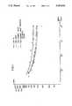
- FIGS. 1 and 2are graphs showing the results of rotary bending fatigue tests carried out on annular test pieces of TA6V treated in various different ways in accordance with the state of the art defined by FR-A-1 322 970 or in accordance with the invention, as indicated by the legends associated with the graphs, said graphs plotting the permissible rotary bending stresses against the number of cycles performed.
- test pieces of TA6V titanium alloy in the cast statewere as follows:
- the first stepis a roughening of the substrate, e.g. by sanding in the dry state with 50 micron corundum or by wet sanding with quartz of 40 microns, an operation shown by tests to be desirable to obtain a satisfactory adherence of the subsequently deposited nickel.
- the partis then placed in a vacuum enclosure at a high secondary vacuum, i.e. at a pressure between 3 ⁇ 10 -4 and 3 ⁇ 10 -1 Pa, and the substrate is subjected to ionic pickling which cleans the substrate by removal of matter.
- the partis placed in an inert gas atmosphere, for example argon injected into the enclosure at a pressure between 1 ⁇ 10 -1 and 50 Pa, while a negative voltage is applied to the substrate so as to attract the ions to the substrate during the luminescent discharge carried out in the enclosure.
- the operationmay be carried out within a power density range of from 0.05 to 0.4 W/cm 2 . Tests have shown that the preferred range is between 0.1 and 0.15 W/cm 2 for a perod of from 15 to 20 minutes.
- the deposition of a keying layer of nickel on the substrateis effected.
- the method chosen for this depositioncomprises cathodic spraying.
- This techniqueis a vacuum deposition process conducted in the cold state, in luminescent plasma, in a gas maintained at a reduced pressure of 0.1 to 10 Pa.
- the material to be deposited, nickel in this instanceis termed the target material and is introduced into the vacuum enclosure in the form of a plate of a few millimeters thickness, this being placed at the cathode position.
- the substrateis placed at the anode position.
- the electric field created between the two electrodesgives rise to ionization of the residual gas which produces a luminescent cloud between the electrodes.
- the substratethen becomes covered with a layer of the same material as the target, due to the condensation of atoms originating from the target under the impact of positive ions contained in the luminescent gas and attracted by the target as a result of its negative polarization.
- the deposition of the keying nickelis carried out by cathodic spraying with a magnetron cathode, so as to improve the quality of adherence of the nickel and increase the deposition rate to obtain an operating time compatible with the demands of industrial production.
- the substrate to be coatedwhich is placed at the anode position, is polarized at a voltage between -20 and -500 V.
- the best resultsare obtained between -100 and -150 V.
- the targetis of pure nickel and is bombarded at a power density between 70 and 700 W/dm 2 , the power density for the bombardment of the target being selected depending upon the temperature admissible by the substrate to be coated.
- Sprayingis carried out in an inert atmosphere within a pressure range of from 0.2 to 5 Pa, the best results being obtained between 0.4 and 0.8 Pa.
- the partthen undergoes an alkaline immersion degreasing operation for from 3 to 7 minutes (typically 5 minutes) in an aqueous bath containing from 30 to 45 g/l of Turco 4215 NCLT or from 40 to 60 g/l Ardrox PST 39 (registered trade marks), followed by rinsing in cold water with monitoring of the water film continuity.
- an alkaline immersion degreasing operationfor from 3 to 7 minutes (typically 5 minutes) in an aqueous bath containing from 30 to 45 g/l of Turco 4215 NCLT or from 40 to 60 g/l Ardrox PST 39 (registered trade marks), followed by rinsing in cold water with monitoring of the water film continuity.
- Electrolytic activation of the partis then effected by dipping it for one minute in an aqueous bath containing from 60 to 80/l KCN and from 10 to 50 g/l K 2 CO 3 at a current density (c.d.) of from 1.5 to 3 A/dm 2 .
- the partis then further rinsed in cold water, after which an electrolytic nickelling operation is performed. This is carried out in two successive stages:
- NiCl 2 .6H 2 Ofrom 280 to 350 g/l
- Ni metalfrom 69 to 86 g/l
- H 3 BO 3from 28 to 35 g/l
- the average deposited thicknessis 15 microns, and the part is again rinsed in fresh water before the next stage.
- Ni sulphamatefrom 75 to 90 g/l
- H 3 BO 3from 30 to 40 g/l
- the thickness of nickel depositedranges from 3 to 5 microns.
- the partis then again rinsed in cold water before being given its anti-wear coating, for example of Cr, Ni-Co, Ni Co Sic or Ag-Ni.
- anti-wear coatingfor example of Cr, Ni-Co, Ni Co Sic or Ag-Ni.
- an electrolytic chromium coatingmay be obtained under the following working conditions:
- the average thickness obtainedis between 120 and 150 microns.
- an anti-wear coating of Ni-Co containing 29% Comay be obtained using a bath in which the Ni/Co mass ratio is 20 and the total Ni+Co in solution is 87.5 g/l.
- the nickel and the cobaltare introduced into the bath in the form of nickel sulphamate Ni (NH 2 SO 3 ) 2 , 4H 2 O and cobalt sulphamate Co (NH 2 SO 3 ) 2 , 4H 2 O, and are deposited under the following operational conditions:
- the partsare placed on a rotary mounting and the bath stirred with compressed air.
- the average coating thickness obtainedis from 120 to 140 microns.
- the partAfter receiving its anti-wear coating, the part is rinsed in cold water and then dried with compressed air, followed by degassing at 200° ⁇ 5° C. for 3 hours.
- test pieces coated in accordance with the inventionwere compared with test pieces coated according to the state of the art as taught by FR-A-1322970.
- Table 1shows the treatment steps applied to 56 test pieces, some of which were left at various intermediate stages of the coating processes before subjecting them to the rotary bending fatigue tests.
- Table 2illustrates the precise operational conditions of the electrolysis carried out in the operations indicated in Table 1.
- FIGS. 1 and 2illustrate the results of the rotary bending fatigue tests, showing the variation of stresses as a function of the number of cycles according to the finished state of the parts, and depending on whether they were obtained by the invention or in accordance with the state of the art.
- Table 3shows the results of vibratory fatigue tests carried out on a number of samples, depending upon the nature of the treatment used for each sample, the number of cycles, and the maximum stresses applied.
- the drop in fatigue limit after 10 8 cycles of parts having undergone only the nickellingis 61% if the part is obtained according to the state of the art, but only 23% if the part is obtained by nickel PVD, then electrolysis as proposed by the invention.
- the drop in fatigue limitis 52% for parts produced according to the state of the art and only 15% for the parts produced in accordance with the invention.
- the differenceis even greater as the drop in fatigue limit is 67% for parts coated according to the state of the art and 27% for the parts coated in accordance with the invention.
- the inventionenables coated titanium parts to be produced for use in restrictive environments where such parts could not previously be used.
- titanium substrateswhich are very much lighter than the materials normally used, for parts subjected to lasting fatigue stresses, due both to rotary bending and to vibrations.
Landscapes
- Chemical & Material Sciences (AREA)
- Organic Chemistry (AREA)
- Engineering & Computer Science (AREA)
- Chemical Kinetics & Catalysis (AREA)
- Materials Engineering (AREA)
- Metallurgy (AREA)
- Electrochemistry (AREA)
- Mechanical Engineering (AREA)
- Composite Materials (AREA)
- Inorganic Chemistry (AREA)
- Electroplating Methods And Accessories (AREA)
- Physical Vapour Deposition (AREA)
- Other Surface Treatments For Metallic Materials (AREA)
- Electroplating And Plating Baths Therefor (AREA)
Abstract
Description
______________________________________ Substrate TA 6 V σ (MPa) (ref.) Prenickelling Ni Co Cr ______________________________________ STATE OF 500 200 170 250 THEART INVENTION 500 380 380 440 ______________________________________
TABLE 1 ______________________________________ TREATMENT STEPS APPLIED IN THE CASE OF ROTARY BENDING FATIGUE TEST PIECES TEST PIECE REFERENCES TREATMENT STEPS ______________________________________ 42-33-26-38-35-29-40 Polished ground condition + Nickel PVD (1) 64-65-66-67-68-69-70 Dry sanding + Nickel PVD (1) 50-51-52-53-54-55-56 Dry sanding + Ni PVD + prenickelling pH = 1.1 + sulphamate nickelling (1) 15-37-32-36-34-30-33 Dry sanding + Ni PVD + prenickelling pH = 1.1 + sulphamate nickelling + nickel-cobalt (1) 25-31-41-36-37-38-39 as above + chromium (1) 9-10-11-12-13-14-16 Dry sanding + activation + prenickelling pH = 1.1 + sulphamate nickelling (2) 57-58-59-60-61-62-63 Same preparation steps + chromium (2) 17-19-20-21-22-23-24 As above + nickel-cobalt (2) ______________________________________ (1) Steps in accordance with the invention (nickel PVD + electrolytic depositions) (2) Steps in accordance with the state of the art (chemical preparation + galvanization)
TABLE 2 __________________________________________________________________________OPERATIONAL ELECTROLYSIS CONDITIONS (*) APPLIED TO THE ROTARY BENDING FATIGUE TEST PIECES Steps according to Steps in accordance the state of the art with the invention c.d. I1 I2 duration c.d. I1 I2 duration BATHS A/dm2 mA mA minutes A/dm2 mA mA minutes __________________________________________________________________________PRENICKELLING 8 540 816 5 7 476 714 3 pH = 1.1 4 272 408 10 4.5 306 459 10 NICKEL-SULPHAMATE 2 135 204 5 2 136 204 5 4 272 408 5 4 272 408 5 CHROMIUM 40 2720 4080 10 25 1700 2550 10 35 2400 3500 8h 20 1360 2040 12h NICKEL-COBALT 2 135 204 10 2 135 204 10 (29% cobalt) 4 272 408 3h25 4 272 408 3h25 __________________________________________________________________________ (*) Rotary mounting I1 = 2 test pieces; I2 = 3 test pieces
TABLE 3 __________________________________________________________________________RESULTS OF VIBRATORY FATIGUE TESTS Maximum Drop in Maximum Drop in stress Fatigue stress Fatigue NATURE OF TREATMENT 10.sup.5 cycles limit 10.sup.8 cycles limit __________________________________________________________________________(1) TA6V reference state 600 MPa / 520 MPa / (2) Polished ground state + Nickel PVD (1) 570 MPa 5% 420 MPa 19% (3) Dry sanding state + nickel PVD (1) 550 MPa 9% 420 MPa 19% (4) Dry sanding + nickel PVD + pre- 550 MPa 9% 400 MPa 23% nickelling + nickel sulphamate (1) (5) Same as treatment (4) + nickel- 480 MPa 20% 380 MPa 27% cobalt 0.1 mm + 3 h 200° C. (1) (6) Same as treatment (4) + chromium 520 MPa 13% 440 MPa 15% 0.1 mm + 3h 200° C. (1) (7) Dry sanding + activation + pre- 400 MPa 33% 200 MPa 61% nickelling + nickel sulphamate (2) (8) Same as treatment (7) + nickel- 300 MPa 50% 170 MPa 67% cobalt 0.1 mm + 3 h 200° C. (2) (9) Same as treatment (7) + chromium 280 MPa 53% 250 MPa 52% 0.1 mm + 3h 200° C. (2) __________________________________________________________________________ (1) Steps in accordance with the invention (nickel PVD + electrolytic depositions) (2) Steps in accordance with the state of the art (chemical preparation + electrolytic depositions)
Claims (12)
Applications Claiming Priority (2)
| Application Number | Priority Date | Filing Date | Title |
|---|---|---|---|
| FR9009554AFR2665185B1 (en) | 1990-07-26 | 1990-07-26 | ANTI-WEAR COATING ON A TITANIUM BASED SUBSTRATE. |
| FR9009554 | 1990-07-26 |
Publications (1)
| Publication Number | Publication Date |
|---|---|
| US5154816Atrue US5154816A (en) | 1992-10-13 |
Family
ID=9399123
Family Applications (1)
| Application Number | Title | Priority Date | Filing Date |
|---|---|---|---|
| US07/736,381Expired - LifetimeUS5154816A (en) | 1990-07-26 | 1991-07-26 | Process for depositing an anti-wear coating on titanium based substrates |
Country Status (8)
| Country | Link |
|---|---|
| US (1) | US5154816A (en) |
| EP (1) | EP0470878B1 (en) |
| JP (1) | JP2564218B2 (en) |
| CN (1) | CN1029995C (en) |
| DE (1) | DE69102687T2 (en) |
| FR (1) | FR2665185B1 (en) |
| RU (1) | RU2068032C1 (en) |
| WO (1) | WO1992001823A1 (en) |
Cited By (8)
| Publication number | Priority date | Publication date | Assignee | Title |
|---|---|---|---|---|
| DE4410369A1 (en)* | 1994-03-25 | 1995-09-28 | Acr Automation In Cleanroom | Plasma priming of light metal useful in electrical, electronics and aircraft industry |
| US20040053197A1 (en)* | 2002-09-16 | 2004-03-18 | Zoran Minevski | Biocompatible implants |
| US20050215350A1 (en)* | 2004-03-23 | 2005-09-29 | Callaway Golf Company | Plated magnesium golf club head |
| US20050221008A1 (en)* | 2004-03-30 | 2005-10-06 | Callaway Golf Company | Method of Plating a Golf Club Head |
| US20070172695A1 (en)* | 2006-01-26 | 2007-07-26 | Hamilton Sundstrand Corporation | Low cost, environmentally favorable, chromium plate replacement coating for improved wear performance |
| DE102008056741A1 (en) | 2008-11-11 | 2010-05-12 | Mtu Aero Engines Gmbh | Wear protection layer for Tial |
| CN106048534A (en)* | 2016-06-03 | 2016-10-26 | 南通市申海工业技术科技有限公司 | Surface treatment process of molybdenum foil for spaceflight interconnection piece |
| CN119144957A (en)* | 2024-11-20 | 2024-12-17 | 鑫鹏源(聊城)智能科技有限公司 | Hydrogen-resistant coating for high-pressure hydrogen-transporting titanium alloy pipeline and preparation method thereof |
Families Citing this family (6)
| Publication number | Priority date | Publication date | Assignee | Title |
|---|---|---|---|---|
| RU2175686C1 (en)* | 2000-05-03 | 2001-11-10 | Институт надежности машин Национальной Академии Наук Беларуси | Composite coating and method of making thereof |
| RU2251589C1 (en)* | 2003-10-21 | 2005-05-10 | Федеральное государственное унитарное предприятие "Всероссийский научно-исследовательский институт авиационных материалов" (ФГУП "ВИАМ") | Method for applying two-layer wear resistant coating on titanium and its alloys |
| DE102004006127A1 (en)* | 2004-02-07 | 2005-08-25 | Dr.Ing.H.C. F. Porsche Ag | Process for the production of corrosion-resistant and decorative coatings and layer systems for substrates of metals |
| RU2398045C1 (en)* | 2008-12-25 | 2010-08-27 | Борис Львович Горберг | Procedure for modifying surface of textile material |
| RU2631573C1 (en)* | 2016-04-11 | 2017-09-25 | Общество с ограниченной ответственностью "Научно-производственное предприятие "Уралавиаспецтехнология" | Method of applying multilayer ion-plasma coating on stamp engraving surface from heat-resistant nickel alloy |
| CN111424303B (en)* | 2020-05-19 | 2021-06-11 | 暨南大学 | SiC nano-silver composite electrodeposition coating and preparation method and application thereof |
Citations (10)
| Publication number | Priority date | Publication date | Assignee | Title |
|---|---|---|---|---|
| FR1322970A (en)* | 1962-02-22 | 1963-04-05 | Snecma | Process for obtaining metallic coatings on titanium and its alloys |
| US3497426A (en)* | 1964-07-02 | 1970-02-24 | Nippon Carbide Kogyo Kk | Manufacture of electrode |
| EP0155611A2 (en)* | 1984-03-21 | 1985-09-25 | Deutsche Lufthansa AG | Process for the electrochemical and chemical deposition of a layer on niobium |
| EP0186266A1 (en)* | 1984-11-19 | 1986-07-02 | Avco Corporation | Erosion-resistant coating system |
| EP0188057A1 (en)* | 1984-11-19 | 1986-07-23 | Avco Corporation | Erosion resistant coatings |
| US4604168A (en)* | 1984-12-20 | 1986-08-05 | General Motors Corporation | Pretreatment for electroplating mineral-filled nylon |
| US4904352A (en)* | 1988-01-13 | 1990-02-27 | Microdot Inc. | Electrodeposited multilayer coating for titanium |
| US4919773A (en)* | 1984-11-19 | 1990-04-24 | Avco Corporation | Method for imparting erosion-resistance to metallic substrates |
| US4931152A (en)* | 1984-11-19 | 1990-06-05 | Avco Corporation | Method for imparting erosion-resistance to metallic substrate |
| US4938850A (en)* | 1988-09-26 | 1990-07-03 | Hughes Aircraft Company | Method for plating on titanium |
- 1990
- 1990-07-26FRFR9009554Apatent/FR2665185B1/ennot_activeExpired - Lifetime
- 1991
- 1991-07-24WOPCT/FR1991/000610patent/WO1992001823A1/enunknown
- 1991-07-24RUSU915011802Apatent/RU2068032C1/ennot_activeIP Right Cessation
- 1991-07-24EPEP91402065Apatent/EP0470878B1/ennot_activeExpired - Lifetime
- 1991-07-24DEDE69102687Tpatent/DE69102687T2/ennot_activeExpired - Fee Related
- 1991-07-25CNCN91105050Apatent/CN1029995C/ennot_activeExpired - Fee Related
- 1991-07-26JPJP3187757Apatent/JP2564218B2/ennot_activeExpired - Fee Related
- 1991-07-26USUS07/736,381patent/US5154816A/ennot_activeExpired - Lifetime
Patent Citations (11)
| Publication number | Priority date | Publication date | Assignee | Title |
|---|---|---|---|---|
| FR1322970A (en)* | 1962-02-22 | 1963-04-05 | Snecma | Process for obtaining metallic coatings on titanium and its alloys |
| US3497426A (en)* | 1964-07-02 | 1970-02-24 | Nippon Carbide Kogyo Kk | Manufacture of electrode |
| EP0155611A2 (en)* | 1984-03-21 | 1985-09-25 | Deutsche Lufthansa AG | Process for the electrochemical and chemical deposition of a layer on niobium |
| US4632734A (en)* | 1984-03-21 | 1986-12-30 | Deutsche Lufthansa Ag | Process for electrochemically or chemically coating niobium |
| EP0186266A1 (en)* | 1984-11-19 | 1986-07-02 | Avco Corporation | Erosion-resistant coating system |
| EP0188057A1 (en)* | 1984-11-19 | 1986-07-23 | Avco Corporation | Erosion resistant coatings |
| US4919773A (en)* | 1984-11-19 | 1990-04-24 | Avco Corporation | Method for imparting erosion-resistance to metallic substrates |
| US4931152A (en)* | 1984-11-19 | 1990-06-05 | Avco Corporation | Method for imparting erosion-resistance to metallic substrate |
| US4604168A (en)* | 1984-12-20 | 1986-08-05 | General Motors Corporation | Pretreatment for electroplating mineral-filled nylon |
| US4904352A (en)* | 1988-01-13 | 1990-02-27 | Microdot Inc. | Electrodeposited multilayer coating for titanium |
| US4938850A (en)* | 1988-09-26 | 1990-07-03 | Hughes Aircraft Company | Method for plating on titanium |
Non-Patent Citations (4)
| Title |
|---|
| John L. Vossen et al, Thin Film Processes, Academic Press, New York, 1978, pp. 11 24.* |
| John L. Vossen et al, Thin Film Processes, Academic Press, New York, 1978, pp. 11-24. |
| Plating & Surface Finishing, vol. 75, No. 2, Feb. 1988, pp. 71 75, T. G. Beat, et al., Plating on Molybdenum .* |
| Plating & Surface Finishing, vol. 75, No. 2, Feb. 1988, pp. 71-75, T. G. Beat, et al., "Plating on Molybdenum". |
Cited By (16)
| Publication number | Priority date | Publication date | Assignee | Title |
|---|---|---|---|---|
| DE4410369A1 (en)* | 1994-03-25 | 1995-09-28 | Acr Automation In Cleanroom | Plasma priming of light metal useful in electrical, electronics and aircraft industry |
| US20040053197A1 (en)* | 2002-09-16 | 2004-03-18 | Zoran Minevski | Biocompatible implants |
| US20040053198A1 (en)* | 2002-09-16 | 2004-03-18 | Lynntech, Inc. | Biocompatible implants |
| US20040053199A1 (en)* | 2002-09-16 | 2004-03-18 | Lynntech, Inc. | Biocompatible implants |
| US20050215350A1 (en)* | 2004-03-23 | 2005-09-29 | Callaway Golf Company | Plated magnesium golf club head |
| US7063628B2 (en) | 2004-03-23 | 2006-06-20 | Callaway Golf Company | Plated magnesium golf club head |
| US20050221008A1 (en)* | 2004-03-30 | 2005-10-06 | Callaway Golf Company | Method of Plating a Golf Club Head |
| US7087268B2 (en) | 2004-03-30 | 2006-08-08 | Callaway Golf Company | Method of plating a golf club head |
| US20070172695A1 (en)* | 2006-01-26 | 2007-07-26 | Hamilton Sundstrand Corporation | Low cost, environmentally favorable, chromium plate replacement coating for improved wear performance |
| US7897265B2 (en) | 2006-01-26 | 2011-03-01 | Hamilton Sundstrand Corporation | Low cost, environmentally favorable, chromium plate replacement coating for improved wear performance |
| US20110114495A1 (en)* | 2006-01-26 | 2011-05-19 | Hamilton Sundstrand Corporation | Low cost, environmentally favorable, chromium plate replacement coating for improved wear performance |
| US8246807B2 (en) | 2006-01-26 | 2012-08-21 | Hamilton Sundstrand Corporation | Low cost, environmentally favorable, chromium plate replacement coating for improved wear performance |
| DE102008056741A1 (en) | 2008-11-11 | 2010-05-12 | Mtu Aero Engines Gmbh | Wear protection layer for Tial |
| WO2010054633A3 (en)* | 2008-11-11 | 2010-12-29 | Mtu Aero Engines Gmbh | Wear-resistant layer for tial |
| CN106048534A (en)* | 2016-06-03 | 2016-10-26 | 南通市申海工业技术科技有限公司 | Surface treatment process of molybdenum foil for spaceflight interconnection piece |
| CN119144957A (en)* | 2024-11-20 | 2024-12-17 | 鑫鹏源(聊城)智能科技有限公司 | Hydrogen-resistant coating for high-pressure hydrogen-transporting titanium alloy pipeline and preparation method thereof |
Also Published As
| Publication number | Publication date |
|---|---|
| CN1029995C (en) | 1995-10-11 |
| DE69102687T2 (en) | 1994-11-17 |
| JP2564218B2 (en) | 1996-12-18 |
| FR2665185B1 (en) | 1992-10-16 |
| EP0470878A1 (en) | 1992-02-12 |
| EP0470878B1 (en) | 1994-06-29 |
| RU2068032C1 (en) | 1996-10-20 |
| WO1992001823A1 (en) | 1992-02-06 |
| DE69102687D1 (en) | 1994-08-04 |
| FR2665185A1 (en) | 1992-01-31 |
| JPH0693469A (en) | 1994-04-05 |
| CN1058429A (en) | 1992-02-05 |
Similar Documents
| Publication | Publication Date | Title |
|---|---|---|
| US5154816A (en) | Process for depositing an anti-wear coating on titanium based substrates | |
| EP0605179B1 (en) | Hard carbon coating-clad base material | |
| US20020177001A1 (en) | Plasma processing container internal member and production method thereof | |
| HK1000424B (en) | Hard carbon coating-clad base material | |
| CN107937875A (en) | A kind of preparation method of Sintered NdFeB magnet surface protection coating | |
| US6913791B2 (en) | Method of surface treating titanium-containing metals followed by plating in the same electrolyte bath and parts made in accordance therewith | |
| US4999259A (en) | Chrome-coated stainless steel having good atmospheric corrosion resistance | |
| GB2058842A (en) | Low overvoltage electrode | |
| JP2934263B2 (en) | Aluminum material and method of manufacturing the same | |
| KR20020050829A (en) | Ni multilayer plated Nd-Fe-B magnet and its manufacturing method | |
| US20240159156A1 (en) | Methods for creating a nickel strike layer and nickel electrolytic bondcoat onto a non-conductive carbon fiber composite surface and the coating system derived therefrom | |
| KR20110078848A (en) | Electrodeposition coating method using vacuum ion plating method | |
| CN109136849B (en) | Pt-modified gradient Al coating and preparation method thereof | |
| JPH10273775A (en) | Abrasion-resistant surface-treated Al or Al-based metal and its production method | |
| JP2576042Y2 (en) | Substrate with carbon hard coating | |
| JP2975120B2 (en) | Method of forming ceramic film | |
| JPS639919A (en) | Manufacture of magnet | |
| JPH02504169A (en) | Method of surface protection against corrosion and wear of metal objects or objects consisting of composite materials with a metal matrix by depositing silicon carbide | |
| JP2001011603A (en) | Member with laminated film and laminated film | |
| KR100320130B1 (en) | Method of forming AlN layer for aluminum parts | |
| JP2000160365A (en) | High corrosion resistant member with coating and its coating | |
| Wielonski et al. | The Effect of Temperatures Developed During Sputter Ion Plating on the Microstructure and Microhardness of AISI 4340 Steel | |
| US20040094423A1 (en) | Method and treating hinge holder | |
| JPH11219809A (en) | Rare earth magnet with high resistance coating | |
| JPS639107A (en) | Manufacture of magnet |
Legal Events
| Date | Code | Title | Description |
|---|---|---|---|
| AS | Assignment | Owner name:SOCIETE NATIONALE D'ETUDE ET DE CONSTRUCTION DE MO Free format text:ASSIGNMENT OF ASSIGNORS INTEREST.;ASSIGNORS:MARTINOU, ROBERT LUCIEN;RUIMI, MICHEL MEYER;REEL/FRAME:006113/0591 Effective date:19910717 | |
| STCF | Information on status: patent grant | Free format text:PATENTED CASE | |
| FEPP | Fee payment procedure | Free format text:PAYOR NUMBER ASSIGNED (ORIGINAL EVENT CODE: ASPN); ENTITY STATUS OF PATENT OWNER: LARGE ENTITY | |
| FPAY | Fee payment | Year of fee payment:4 | |
| FPAY | Fee payment | Year of fee payment:8 | |
| FEPP | Fee payment procedure | Free format text:PAYER NUMBER DE-ASSIGNED (ORIGINAL EVENT CODE: RMPN); ENTITY STATUS OF PATENT OWNER: LARGE ENTITY Free format text:PAYOR NUMBER ASSIGNED (ORIGINAL EVENT CODE: ASPN); ENTITY STATUS OF PATENT OWNER: LARGE ENTITY | |
| AS | Assignment | Owner name:SNECMA MOTEURS, FRANCE Free format text:CHANGE OF NAME;ASSIGNOR:SOCIETE NATIONALE D'ETUDES ET DE CONSTRUCTION DE MOTEURS D'AVIATION;REEL/FRAME:014754/0192 Effective date:20000117 | |
| FPAY | Fee payment | Year of fee payment:12 | |
| AS | Assignment | Owner name:SNECMA, FRANCE Free format text:CHANGE OF NAME;ASSIGNOR:SNECMA MOTEURS;REEL/FRAME:020609/0569 Effective date:20050512 Owner name:SNECMA,FRANCE Free format text:CHANGE OF NAME;ASSIGNOR:SNECMA MOTEURS;REEL/FRAME:020609/0569 Effective date:20050512 |