US5154708A - Unitary scalpel for contact laser surgery - Google Patents
Unitary scalpel for contact laser surgeryDownload PDFInfo
- Publication number
- US5154708A US5154708AUS07/678,170US67817091AUS5154708AUS 5154708 AUS5154708 AUS 5154708AUS 67817091 AUS67817091 AUS 67817091AUS 5154708 AUS5154708 AUS 5154708A
- Authority
- US
- United States
- Prior art keywords
- support member
- laser
- conductor
- scalpel
- laser energy
- Prior art date
- Legal status (The legal status is an assumption and is not a legal conclusion. Google has not performed a legal analysis and makes no representation as to the accuracy of the status listed.)
- Expired - Lifetime
Links
Images

Classifications
- A—HUMAN NECESSITIES
- A61—MEDICAL OR VETERINARY SCIENCE; HYGIENE
- A61B—DIAGNOSIS; SURGERY; IDENTIFICATION
- A61B18/00—Surgical instruments, devices or methods for transferring non-mechanical forms of energy to or from the body
- A61B18/18—Surgical instruments, devices or methods for transferring non-mechanical forms of energy to or from the body by applying electromagnetic radiation, e.g. microwaves
- A61B18/20—Surgical instruments, devices or methods for transferring non-mechanical forms of energy to or from the body by applying electromagnetic radiation, e.g. microwaves using laser
- A61B18/22—Surgical instruments, devices or methods for transferring non-mechanical forms of energy to or from the body by applying electromagnetic radiation, e.g. microwaves using laser the beam being directed along or through a flexible conduit, e.g. an optical fibre; Couplings or hand-pieces therefor
Definitions
- the present inventionrelates to scalpels for contact laser surgery, in particular, to scalpels intended for use in conjunction with, or as an integral member of, a flexible optical fiber delivery system.
- Such delivery systemsare generally used, for example, with Nd:Yag and other lasers of wavelength suitable the for efficient transfer of laser energy through an optical fiber medium.
- the present scalpelfinds particular application in orthopedic surgery, for example, in the removal of damaged meniscus from the knee.
- the operative situs for such a procedureis commonly and preferably surrounded by water. This presence of water, however, creates significant problems for contact laser scalpels of conventional design.
- the tip region of the contact scalpelnecessarily heats following any sustained interval of cutting.
- the heated tipis suddenly exposed and emersed in the relatively cool liquid surrounding the cut location thereby causing a corresponding rapid cooling of the tip.
- This coolinghas been known to weaken or even fracture the sapphire or other crystalline material of which conventional laser scalpels are fabricated.
- the contact laser scalpel of the present inventionhas been developed to overcome this and certain other known problems associated with conventional non-unitary scalpel configurations.
- the present scalpeldoes not utilize conventional sapphire or similar optically transparent contact members--at least, not in such configuration as to expose the material to the rigors of extreme temperature cycling. Rather, the optically active elements of the present invention are at least partially encased within, and protected by, an opaque ceramic ferrule, preferably of alumina, which material exhibits numerous advantageous properties with particular reference to aqueous environments.
- the coefficient of thermal conductivity of aluminais quite low.
- the heat which is generated at the distal tip end region of the probeis not propagated along the probe and handle and therefore does not ordinarily heat non-active portions of the scalpel system.
- this heatis this heat communicated to the ferrule core where such fiber is located.
- a further and very significant property of aluminais its resistance to thermal shock-induced fracturing. This problem is particularly acute, as noted, in certain orthopedic applications where the scalpel must be withdrawn from the meniscus through its surrounding fluid environment.
- Aluminahas been found to exhibit greater tolerance to the lateral sheer loads to which a scalpel is invariably subjected during any cutting procedure.
- the alumina ferruleis not, however, an active element of the scalpel in an optical sense. Indeed, alumina and most similar ceramic materials are opaque to the laser wavelengths of interest.
- optical focusing of the laser energy to the tip end region of the scalpelis achieved by placement of a narrow optical fiber within the ferrule, along the central axis thereof.
- This fiberis of uniform diameter and is preferably formed as an extension, in whole or in part, of the delivery system optical fiber, i.e. the fiber through which the laser energy is conveyed from the laser to the operative situs.
- a fiber of greater diameteris employed with the fiber and ceramic ferrule combination being ground or otherwise machined to form a tapered conical profile.
- the fiberwill be seen to extend forwardly of the reinforcing ceramic ferrule.
- the present scalpelprovides, in addition to the above-enumerated advantages associated with the ceramic ferrule itself, the elimination of the interface between fiber and scalpel contact member. This advantage may be realized with either the narrow or wider tapered fiber embodiments of the present invention.
- This interfacerepresents a perennial problem area in contact laser probe and scalpel implementation.
- the threaded connectors which affix the scalpel to the fiber optic delivery systemmust be of accurate design, thread, placement, and construction in order to assure proper alignment between the delivery fiber and the scalpel. Not only are the metallic couplings expensive, but their retention often requires grooves or other indentations in the sapphire thereby causing potential stress breakage points.
- the angle of dispersion from the end of a bald, unfocused optical fiberis generally rather narrow, e.g. about 10 degrees, and therefore is not appropriate for many surgical applications.
- the dispersion angle for conventional sapphire contact laser probesis approximately 25-35 degrees.
- the narrow fiber embodiment of the present scalpelovercomes these restrictions by limiting the diameter of the ceramic ferrule in the tip end region, preferably to about twice the fiber diameter or less. Further, the fiber is extended into flush relationship with the distal end of the ceramic thereby permitting or causing the corresponding distal end of the fiber to, as presently understood, partially liquify and/or recrystallize, in turn, resulting in a wider energy dispersion profile.
- the ceramic ferruleserves these additional functions including the support of the otherwise highly flexible fiber as well as the maintenance of the integrity of the distal portion of such fiber when the latter is subjected to the elevated temperature regime associated with actual scalpel operation.
- the fiberitself generally defines a tapered conical extension from the ceramic ferrule and serves to contain or focus the laser energy to the tip end of the tapered fiber as taught, for example, in U.S. Pat. No. 4,693,244, owned by the present applicant.
- an optically transparent enamelis baked onto the surface of scalpel, generally from the tip region back between 1 and 2 mm.
- This coatingmay advantageously contain infrared absorbing material as taught in U.S. Pat. No. 4,736,743, although such is not required for the practice of this invention.
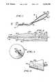
- FIG. 1is a front elevation view of the narrow fiber embodiment of the ceramic laser scalpel of the present invention shown affixed to handpiece;
- FIG. 2is a sectional view of the ceramic laser scalpel taken along line 2--2 of FIG. 1;
- FIG. 3is a left side elevation view of the ceramic scalpel of FIG. 1;
- FIG. 4is an enlarged fragmentary front elevation view of the tip end region of the ceramic scalpel of FIG. 1 illustrating the enamel coating thereon;
- FIG. 5is a front elevation view of the wider fiber embodiment of the present invention.
- FIG. 6is a front elevation view of the ceramic ferrule used in connection with the scalpel of FIG. 5 prior to the assembly and conical machining thereof;
- FIG. 7is a front elevation view of a partially assembled scalpel of FIG. 5 illustrating the positioning of the unmachined ceramic ferrule on the optical fiber;
- FIG. 8is a front elevation view of a partially assembled scalpel of FIG. 5 shown with the metal wand in position prior to the machining of the ceramic and fiber.
- the narrow fiber contact laser ceramic scalpel 10 of the present inventionis shown positioned at the distal end of a surgical handpiece 12.
- Handpiece 12is of conventional design having a widened body portion or handle 14 with a tubular member or wand 16 extending therefrom.
- a channel or opening 18is provided in the handpiece through which an optical fiber system 20 passes.
- This systemis also of known design and includes an optical fiber 22, preferably of fused silica, through which the laser energy is channelled and a protective sheathing 24 concentrically thereon.
- optical fibers of varying diametersare found in connection with known contact laser probes and scalpels, a fiber of relatively narrow diameter, for example 200 microns, is preferred for the present extended-fiber ceramic scalpel--this by reason that the delivery system fiber extends through, and thereby defines, the entire optical path of the scalpel itself.
- the present scalpelincludes a tapered or conically-shaped ferrule 26 fabricated from a ceramic material of high sheer strength and low thermal conductivity.
- Aluminahas been found to be satisfactory and is preferred in view of its extremely low thermal conductivity (0.07 cal/cm.sec.° C.) and its proven resistance to mechanical failure under ordinary surgical conditions.
- the present ceramic scalpel 10is positioned and affixed to the distal end of the handpiece wand 16. More specifically, the rear or input portion 28 of the ferrule is machined, or molded, to a diameter generally equal to the inside dimension of the tubular member thereby permitting the ferrule to be snugly received therein.
- the diameter of the cylindrical body portion 30 of the ferruleis preferably the same as that of the wand 16 thereby defining a smooth, even transition between the scalpel and handpiece.
- the forward scalpel region 32is of conical profile having, in one preferred arrangement, a taper angle of approximately 8 degrees. This taper extends from its widest diameter generally, as noted, equal to that of the tubular member, to a narrow cross-section at the scalpel tip end 34 preferably in the order of twice the diameter of the fiber or, in the present case, to a diameter of 400 microns.
- the enlarged side elevation or end view of FIG. 3illustrates the cylindrical body, the narrow tip, and fiber diameters, respectively, as 36, 38, and 40.
- tip end diameters 38may be utilized. However, proper scalpel cutting action may be comprised as the tip end diameter is increased. Tip diameters in excess of 3 or 4 times that of the fiber are not, as presently understood, suitable.
- a hole or passage 42is provided along the longitudinal scalpel axis through which an extended portion of fiber 22 is passed.
- This holeis of appropriate diameter to snugly receive fiber 22 therein, although retention of the fiber within the scalpel may be assured by, for example, epoxying the fiber to the rear portion of the scalpel as shown at 46 (FIG. 2).
- the distal end 44 of this fiberis positioned, or cleaved, flush with the scalpel tip end 34.
- the present ferruleincluding machining, molding, and drawing or extrusion.
- the preferred manner of manufactureis by drawing or extruding the ferrule with a pin member in the die to form the axial fiber passage 42.
- the present extended fiber scalpelprovides for the transmission of the laser energy from the laser source (not shown) to the point of operative tissue contact (i.e. at the scalpel tip end 34) along a single continuous fiber path without the fiber-to-scalpel interface ordinarily found in other contact laser instruments. Such interfaces necessarily exhibit losses which, in turn, require cooling or restricted operating regimes to limit unacceptable heat concentrations.
- the present scalpelprovides conventional cutting action, and does so in the hostile liquid-filled environment characteristic of orthopedic surgery, while simultaneously exhibiting improved strength, fracture resistance, and little or no requirement for scalpel cooling.
- a connectormay be provided to permit removal of the scalpel and/or handpiece from the laser delivery system optical fiber, but, at a spaced, remote location from the scalpel. In this manner, fibers and scalpels may be exchanged or replaced as required without having to place an optical fiber-to-scalpel interface adjacent the operative site.
- Bare optical fibers of conventional designfor example the 200 micron fiber 22 of the present scalpel, ordinarily exhibit radiation divergence angles which are too narrow for surgical applications--typically in the order of about 8 degrees. Divergence angles of between two and three or more times that of a bare fiber are considered standard for best scalpel operation.
- the present structuredoes not exhibit the narrow divergence characteristic of conventional bare fibers.
- Use of the low thermal conductivity ferrule, with its relatively narrow cross-section in the tip end region, and the partial exposure of the optical fiber at the scalpel tip end 34combine to create a scalpel of wider laser divergence.
- the ceramic material at the extreme scalpel tip endlocally heats due, as noted, to its narrow cross-section and low thermal conductivity. This heating, in combination with the exposed nature of the fiber tip itself, is believed to cause a slight structural realignment or bubbling of the fiber tip which, in turn, results in a greater laser radiation divergence angle.
- the ceramic ferruleserves several important functions.
- the ferruleprovides the necessary strength and rigidity to an otherwise flexible fiber and, importantly protects the fiber against undue thermal deterioration.
- the narrowed tip region of the ceramic ferruleprovides the requisite strength and protection of the optical fiber while simultaneously cooperating in the limited restructuring of the fiber which, in turn, facilitates increased laser divergence.
- FIG. 4illustrates another embodiment of the present invention adapted to further enhance the laser divergence angle.
- the tip end of the scalpel described above(FIGS. 1-3) is dipped in an enamel silica paste and thereafter baked to cure or harden the coating 48.
- the enamel coatingimproves scalpel cutting by further enhancing the laser divergence angle and by conducting heat energy through the coating thereby to create limited side heating in the tip end region of the scalpel.
- the enamel coatingis applied to the tip end region, typically covering about 11/2 mm, although extended or more restricted applications may be applied to create scalpels having correspondingly differing side cutting characteristics.
- FIGS. 5-8illustrate yet another embodiment of the present scalpel employing a wider diameter optical fiber 50, for example 1000 ⁇ .
- the present embodimentpreferably employs a continuous fiber that interconnects the source of laser energy with the operative situs. In this manner, additional laser energy interfaces may be avoided.
- the ceramic ferrule 52defines a tapered, conical profile 54.
- the ferrulecannot be machined to narrow point. Rather, as set forth more fully hereinafter, the ceramic ferrule and optical fiber or jointly machined to form an overall tapered, conical profile in which the distal end of the optical fiber 56 is, itself, tapered and thereby extending forwardly of the ferrule to define a surgical cutting surface.
- FIG. 6depicts the ceramic ferrule blank 58 prior to assembly and machining into its tapered form.
- Ferrule blank 58is of cylindrical cross-section having, as previously described, an outer diameter 60 generally equal to that of the supporting wand 62 (FIGS. 5 and 8) and a narrower diameter portion 64 adapted for insertion into the distal end of the tubular wand 62.
- the unmachined blankis approximately 0.31 inches in length.
- An aperture 66is provided along the longitudinal axis of the ferrule blank through which the optical fiber is passed. More specifically, and referring to FIG. 7, the ceramic ferrule blank 58 is slipped onto the optical fiber 50 after approximately 3/8 inch of cladding has been removed therefrom. The blank is held in position by an expoxy, for example, No. 353. Thereafter the tubular wand 62 is slipped and epoxied into position as shown in FIG. 8.
- Wand 50includes a wing member 68 rigidly affixed thereto. This member is within the plastic housing or handle 70 thereby precluding the angular movement of the wand with respect to the handle. This is particularly important where offset or angled wands of the type illustrated at 16 in FIG. 1 are employed.
- the assembled wand/fiber/ferrule of FIG. 8is thereafter placed, for example, in a spin fixture where a diamond wheel machines the requisite taper into the distal end of the scalpel, in particular, into the assembled ceramic ferrule and optical fiber combination thereby forming the tapered ferrule and fiber surfaces respectively at 54 and 56 of FIG. 5.
- the tapered end of the optical fibermay thereafter be roughened, by bead blasting or otherwise, to facilitate adhesion of an infrared coating material as set forth in U.S. Pat. No. 4,736,743.
- the above-described wide-diameter scalpelalso represents a strong and substantially inflexible surgical instrument--such structural integrity being attributable to the combination of the inherent strength of the 1000 ⁇ fiber and, importantly, the ceramic ferrule support member.
Landscapes
- Health & Medical Sciences (AREA)
- Surgery (AREA)
- Physics & Mathematics (AREA)
- Life Sciences & Earth Sciences (AREA)
- Engineering & Computer Science (AREA)
- Medical Informatics (AREA)
- Nuclear Medicine, Radiotherapy & Molecular Imaging (AREA)
- Electromagnetism (AREA)
- Optics & Photonics (AREA)
- Biomedical Technology (AREA)
- Heart & Thoracic Surgery (AREA)
- Otolaryngology (AREA)
- Molecular Biology (AREA)
- Animal Behavior & Ethology (AREA)
- General Health & Medical Sciences (AREA)
- Public Health (AREA)
- Veterinary Medicine (AREA)
- Laser Surgery Devices (AREA)
- Surgical Instruments (AREA)
Abstract
Description
Claims (5)
Priority Applications (6)
| Application Number | Priority Date | Filing Date | Title |
|---|---|---|---|
| US07/678,170US5154708A (en) | 1990-05-15 | 1991-03-29 | Unitary scalpel for contact laser surgery |
| CA002042308ACA2042308A1 (en) | 1990-05-15 | 1991-05-10 | Unitary scalpel for contact laser surgery |
| DE69114358TDE69114358D1 (en) | 1990-05-15 | 1991-05-14 | One-piece scalpel for contact laser surgery. |
| AT91304300TATE129878T1 (en) | 1990-05-15 | 1991-05-14 | ONE-PIECE SCALPEL FOR CONTACT LASER SURGERY. |
| EP91304300AEP0458506B1 (en) | 1990-05-15 | 1991-05-14 | Unitary scalpel for contact laser surgery |
| JP3138656AJPH0685782B2 (en) | 1990-05-15 | 1991-05-15 | Contact laser surgical scalpel |
Applications Claiming Priority (2)
| Application Number | Priority Date | Filing Date | Title |
|---|---|---|---|
| US52388490A | 1990-05-15 | 1990-05-15 | |
| US07/678,170US5154708A (en) | 1990-05-15 | 1991-03-29 | Unitary scalpel for contact laser surgery |
Related Parent Applications (1)
| Application Number | Title | Priority Date | Filing Date |
|---|---|---|---|
| US52388490AContinuation-In-Part | 1990-05-15 | 1990-05-15 |
Publications (1)
| Publication Number | Publication Date |
|---|---|
| US5154708Atrue US5154708A (en) | 1992-10-13 |
Family
ID=27061298
Family Applications (1)
| Application Number | Title | Priority Date | Filing Date |
|---|---|---|---|
| US07/678,170Expired - LifetimeUS5154708A (en) | 1990-05-15 | 1991-03-29 | Unitary scalpel for contact laser surgery |
Country Status (6)
| Country | Link |
|---|---|
| US (1) | US5154708A (en) |
| EP (1) | EP0458506B1 (en) |
| JP (1) | JPH0685782B2 (en) |
| AT (1) | ATE129878T1 (en) |
| CA (1) | CA2042308A1 (en) |
| DE (1) | DE69114358D1 (en) |
Cited By (25)
| Publication number | Priority date | Publication date | Assignee | Title |
|---|---|---|---|---|
| US5495541A (en)* | 1994-04-19 | 1996-02-27 | Murray; Steven C. | Optical delivery device with high numerical aperture curved waveguide |
| WO1998011462A1 (en)* | 1996-09-16 | 1998-03-19 | Focal, Inc. | Optical fiber diffuser and method of making |
| US5756015A (en)* | 1995-06-06 | 1998-05-26 | Ngk Insulators, Ltd. | Method for producing cylindrical ceramic body |
| WO2001028447A1 (en) | 1999-10-19 | 2001-04-26 | Wolfgang Illich | Method and system for laser surgery |
| US6383179B1 (en)* | 1999-08-11 | 2002-05-07 | Ceramoptec Industries Inc. | Diode laser scalpel |
| US20040010248A1 (en)* | 2002-07-10 | 2004-01-15 | Appling William M. | Endovascular treatment device having a fiber tip spacer |
| US6709167B2 (en)* | 2000-09-27 | 2004-03-23 | Kyoueisenzai Kabushiki Gaisha | Composite ferrule of connector for optical fibers, and method of manufacturing the same |
| US20040114879A1 (en)* | 2002-09-27 | 2004-06-17 | Dornier Medtech Laser Gmbh | Laser with intelligent therapeutic fiber |
| US20050288655A1 (en)* | 2004-06-29 | 2005-12-29 | Howard Root | Laser fiber for endovenous therapy having a shielded distal tip |
| US20070014521A1 (en)* | 2005-04-18 | 2007-01-18 | Dornier Medtech Laser Gmbh | Optical fibre |
| US20070155669A1 (en)* | 2005-12-30 | 2007-07-05 | Dornier Medtech Laser Gmbh | Treatment of cancer by a combination of non-ionizing radiation and androgen deprivation |
| US20070179486A1 (en)* | 2004-06-29 | 2007-08-02 | Jeff Welch | Laser fiber for endovenous therapy having a shielded distal tip |
| US20070260231A1 (en)* | 2005-04-21 | 2007-11-08 | Ondine International, Ltd. | Optical probe for delivery of light |
| US20080158629A1 (en)* | 2006-10-17 | 2008-07-03 | Dornier Medtech Laser Gmbh | Light guide |
| US20080188843A1 (en)* | 2002-07-10 | 2008-08-07 | Appling William M | Device and method for endovascular treatment for causing closure of a blood vessel |
| US20110125140A1 (en)* | 2008-04-25 | 2011-05-26 | Domier MedTech Laser GmbH | Light-Based Method for the Endovascular Treatment of Pathologically Altered Blood Vessels |
| US9782562B2 (en) | 2002-04-04 | 2017-10-10 | Angiodynamics, Inc. | Venous insufficiency treatment method |
| US9814513B2 (en) | 2011-06-30 | 2017-11-14 | Angiodynamics, Inc. | Endovascular plasma treatment device and method of use |
| CN113069203A (en)* | 2021-03-23 | 2021-07-06 | 江西麦帝施科技有限公司 | Stepped temperature working system and method for surgical tool bit of laser surgical system |
| US11154380B2 (en) | 2017-10-26 | 2021-10-26 | King Abdulaziz University | Dental restoration scalpel |
| US11369398B2 (en) | 2020-08-19 | 2022-06-28 | Tag Dream Medical Ltd. | Hybrid laser cutter |
| US11576724B2 (en) | 2011-02-24 | 2023-02-14 | Eximo Medical Ltd. | Hybrid catheter for vascular intervention |
| US11684420B2 (en) | 2016-05-05 | 2023-06-27 | Eximo Medical Ltd. | Apparatus and methods for resecting and/or ablating an undesired tissue |
| US12038322B2 (en) | 2022-06-21 | 2024-07-16 | Eximo Medical Ltd. | Devices and methods for testing ablation systems |
| US12376904B1 (en) | 2020-09-08 | 2025-08-05 | Angiodynamics, Inc. | Dynamic laser stabilization and calibration system |
Families Citing this family (1)
| Publication number | Priority date | Publication date | Assignee | Title |
|---|---|---|---|---|
| CN111419393B (en)* | 2020-04-13 | 2024-07-09 | 西安交通大学医学院第一附属医院 | Magnetic anchoring laser energy device for stab reduction card endoscopic surgery |
Citations (11)
| Publication number | Priority date | Publication date | Assignee | Title |
|---|---|---|---|---|
| US3467098A (en)* | 1967-03-24 | 1969-09-16 | Becton Dickinson Co | Flexible conduit for laser surgery |
| US3834391A (en)* | 1973-01-19 | 1974-09-10 | Block Carol Ltd | Method and apparatus for photoepilation |
| DE2821265A1 (en)* | 1977-05-16 | 1978-11-23 | Olympus Optical Co | LASER SCALPEL |
| US4170997A (en)* | 1977-08-26 | 1979-10-16 | Hughes Aircraft Company | Medical laser instrument for transmitting infrared laser energy to a selected part of the body |
| DE2826383A1 (en)* | 1978-06-16 | 1979-12-20 | Eichler Juergen | Probe for laser surgery - is tubular and placed against or inserted in tissue, with or without heated end |
| GB2154761A (en)* | 1984-02-21 | 1985-09-11 | Quentron Optics Pty Ltd | Diffusive optical fibre termination |
| US4576177A (en)* | 1983-02-18 | 1986-03-18 | Webster Wilton W Jr | Catheter for removing arteriosclerotic plaque |
| US4592353A (en)* | 1984-05-22 | 1986-06-03 | Surgical Laser Technologies Ohio, Inc. | Medical and surgical laser probe |
| US4693244A (en)* | 1984-05-22 | 1987-09-15 | Surgical Laser Technologies, Inc. | Medical and surgical laser probe I |
| US4736743A (en)* | 1986-05-12 | 1988-04-12 | Surgical Laser Technology, Inc. | Vaporization contact laser probe |
| WO1990001907A1 (en)* | 1988-08-25 | 1990-03-08 | Arthur Vassiliadis | Dental laser assembly |
Family Cites Families (3)
| Publication number | Priority date | Publication date | Assignee | Title |
|---|---|---|---|---|
| JPS6125544A (en)* | 1984-07-17 | 1986-02-04 | アロカ株式会社 | Laser medical optical fiber applicator |
| JPS6125545A (en)* | 1984-07-17 | 1986-02-04 | アロカ株式会社 | Laser medical optical fiber applicator |
| JPS63115552A (en)* | 1986-11-04 | 1988-05-20 | 星野 雅彦 | Laser knife |
- 1991
- 1991-03-29USUS07/678,170patent/US5154708A/ennot_activeExpired - Lifetime
- 1991-05-10CACA002042308Apatent/CA2042308A1/ennot_activeAbandoned
- 1991-05-14DEDE69114358Tpatent/DE69114358D1/ennot_activeExpired - Lifetime
- 1991-05-14ATAT91304300Tpatent/ATE129878T1/enactive
- 1991-05-14EPEP91304300Apatent/EP0458506B1/ennot_activeExpired - Lifetime
- 1991-05-15JPJP3138656Apatent/JPH0685782B2/ennot_activeExpired - Lifetime
Patent Citations (12)
| Publication number | Priority date | Publication date | Assignee | Title |
|---|---|---|---|---|
| US3467098A (en)* | 1967-03-24 | 1969-09-16 | Becton Dickinson Co | Flexible conduit for laser surgery |
| US3834391A (en)* | 1973-01-19 | 1974-09-10 | Block Carol Ltd | Method and apparatus for photoepilation |
| DE2821265A1 (en)* | 1977-05-16 | 1978-11-23 | Olympus Optical Co | LASER SCALPEL |
| US4170997A (en)* | 1977-08-26 | 1979-10-16 | Hughes Aircraft Company | Medical laser instrument for transmitting infrared laser energy to a selected part of the body |
| DE2826383A1 (en)* | 1978-06-16 | 1979-12-20 | Eichler Juergen | Probe for laser surgery - is tubular and placed against or inserted in tissue, with or without heated end |
| US4576177A (en)* | 1983-02-18 | 1986-03-18 | Webster Wilton W Jr | Catheter for removing arteriosclerotic plaque |
| GB2154761A (en)* | 1984-02-21 | 1985-09-11 | Quentron Optics Pty Ltd | Diffusive optical fibre termination |
| US4592353A (en)* | 1984-05-22 | 1986-06-03 | Surgical Laser Technologies Ohio, Inc. | Medical and surgical laser probe |
| US4693244A (en)* | 1984-05-22 | 1987-09-15 | Surgical Laser Technologies, Inc. | Medical and surgical laser probe I |
| US4592353B1 (en)* | 1984-05-22 | 1989-04-18 | ||
| US4736743A (en)* | 1986-05-12 | 1988-04-12 | Surgical Laser Technology, Inc. | Vaporization contact laser probe |
| WO1990001907A1 (en)* | 1988-08-25 | 1990-03-08 | Arthur Vassiliadis | Dental laser assembly |
Cited By (44)
| Publication number | Priority date | Publication date | Assignee | Title |
|---|---|---|---|---|
| US5495541A (en)* | 1994-04-19 | 1996-02-27 | Murray; Steven C. | Optical delivery device with high numerical aperture curved waveguide |
| US5756015A (en)* | 1995-06-06 | 1998-05-26 | Ngk Insulators, Ltd. | Method for producing cylindrical ceramic body |
| WO1998011462A1 (en)* | 1996-09-16 | 1998-03-19 | Focal, Inc. | Optical fiber diffuser and method of making |
| US6004315A (en)* | 1996-09-16 | 1999-12-21 | Focal, Inc. | Optical fiber diffuser and method of making |
| US6383179B1 (en)* | 1999-08-11 | 2002-05-07 | Ceramoptec Industries Inc. | Diode laser scalpel |
| WO2001028447A1 (en) | 1999-10-19 | 2001-04-26 | Wolfgang Illich | Method and system for laser surgery |
| US6709167B2 (en)* | 2000-09-27 | 2004-03-23 | Kyoueisenzai Kabushiki Gaisha | Composite ferrule of connector for optical fibers, and method of manufacturing the same |
| US9782562B2 (en) | 2002-04-04 | 2017-10-10 | Angiodynamics, Inc. | Venous insufficiency treatment method |
| US20090264875A1 (en)* | 2002-07-10 | 2009-10-22 | Appling William M | Method of Treating a Blood Vessel with an Optical Fiber Having a Spacer |
| US20080015559A1 (en)* | 2002-07-10 | 2008-01-17 | Appling William M | Endovascular treatment device having a fiber tip spacer |
| US10238453B2 (en) | 2002-07-10 | 2019-03-26 | Angiodynamics, Inc. | Method of making an endovascular laser treatment device for causing closure of a blood vessel |
| US7559329B2 (en) | 2002-07-10 | 2009-07-14 | Angiodynamics, Inc. | Method of treating a blood vessel with an optical fiber having a spacer |
| US8864755B2 (en) | 2002-07-10 | 2014-10-21 | Angiodynamics, Inc. | Device and method for endovascular treatment for causing closure of a blood vessel |
| US8425501B2 (en) | 2002-07-10 | 2013-04-23 | Angiodynamics, Inc. | Method of treating a blood vessel with an optical fiber having a spacer |
| US8864754B2 (en) | 2002-07-10 | 2014-10-21 | Angiodynamics, Inc. | Device and method for endovascular treatment for causing closure of a blood vessel |
| US20040010248A1 (en)* | 2002-07-10 | 2004-01-15 | Appling William M. | Endovascular treatment device having a fiber tip spacer |
| US8840606B2 (en) | 2002-07-10 | 2014-09-23 | Angiodynamics, Inc. | Method of treating a blood vessel with an optical fiber having a spacer |
| US20080188843A1 (en)* | 2002-07-10 | 2008-08-07 | Appling William M | Device and method for endovascular treatment for causing closure of a blood vessel |
| US20070150032A1 (en)* | 2002-09-27 | 2007-06-28 | Dornier Medtech Laser Gmbh | Laser with intelligent therapeutic fiber |
| US20040114879A1 (en)* | 2002-09-27 | 2004-06-17 | Dornier Medtech Laser Gmbh | Laser with intelligent therapeutic fiber |
| US20070179486A1 (en)* | 2004-06-29 | 2007-08-02 | Jeff Welch | Laser fiber for endovenous therapy having a shielded distal tip |
| US20050288655A1 (en)* | 2004-06-29 | 2005-12-29 | Howard Root | Laser fiber for endovenous therapy having a shielded distal tip |
| US7503701B2 (en) | 2005-04-18 | 2009-03-17 | Dornier Medtech Laser Gmbh | Systems and methods for cleaning an optical fibre |
| US20070014521A1 (en)* | 2005-04-18 | 2007-01-18 | Dornier Medtech Laser Gmbh | Optical fibre |
| US20070260231A1 (en)* | 2005-04-21 | 2007-11-08 | Ondine International, Ltd. | Optical probe for delivery of light |
| US20080200395A1 (en)* | 2005-12-30 | 2008-08-21 | Dornier Medtech Laser Gmbh | Treatment of cancer by a combination of non-ionizing radiation and androgen deprivation |
| US20070155669A1 (en)* | 2005-12-30 | 2007-07-05 | Dornier Medtech Laser Gmbh | Treatment of cancer by a combination of non-ionizing radiation and androgen deprivation |
| US8114068B2 (en) | 2006-10-17 | 2012-02-14 | Dornier Medtech Laser Gmbh | Light guide |
| US20080158629A1 (en)* | 2006-10-17 | 2008-07-03 | Dornier Medtech Laser Gmbh | Light guide |
| US20110125140A1 (en)* | 2008-04-25 | 2011-05-26 | Domier MedTech Laser GmbH | Light-Based Method for the Endovascular Treatment of Pathologically Altered Blood Vessels |
| US9168098B2 (en) | 2008-04-25 | 2015-10-27 | Dornier Medtech Laser Gmbh | Light-based method for the endovascular treatment of pathologically altered blood vessels |
| US9149334B2 (en) | 2008-04-25 | 2015-10-06 | Dornier Medtech Laser Gmbh | Light-based method for the endovascular treatment of pathologically altered blood vessels |
| US12042223B2 (en) | 2011-02-24 | 2024-07-23 | Eximo Medical Ltd. | Hybrid catheter for vascular intervention |
| US11576724B2 (en) | 2011-02-24 | 2023-02-14 | Eximo Medical Ltd. | Hybrid catheter for vascular intervention |
| US9814513B2 (en) | 2011-06-30 | 2017-11-14 | Angiodynamics, Inc. | Endovascular plasma treatment device and method of use |
| US11684420B2 (en) | 2016-05-05 | 2023-06-27 | Eximo Medical Ltd. | Apparatus and methods for resecting and/or ablating an undesired tissue |
| US11154380B2 (en) | 2017-10-26 | 2021-10-26 | King Abdulaziz University | Dental restoration scalpel |
| US11219503B2 (en) | 2017-10-26 | 2022-01-11 | King Abdulaziz University | Method for contouring a dental restoration |
| US11219504B1 (en) | 2017-10-26 | 2022-01-11 | King Abdulaziz University | Dental cosmetic scalpel |
| US11638591B2 (en) | 2020-08-19 | 2023-05-02 | Tag Dream Medical Ltd. | Hybrid laser cutter |
| US11369398B2 (en) | 2020-08-19 | 2022-06-28 | Tag Dream Medical Ltd. | Hybrid laser cutter |
| US12376904B1 (en) | 2020-09-08 | 2025-08-05 | Angiodynamics, Inc. | Dynamic laser stabilization and calibration system |
| CN113069203A (en)* | 2021-03-23 | 2021-07-06 | 江西麦帝施科技有限公司 | Stepped temperature working system and method for surgical tool bit of laser surgical system |
| US12038322B2 (en) | 2022-06-21 | 2024-07-16 | Eximo Medical Ltd. | Devices and methods for testing ablation systems |
Also Published As
| Publication number | Publication date |
|---|---|
| CA2042308A1 (en) | 1991-11-16 |
| JPH04231038A (en) | 1992-08-19 |
| EP0458506B1 (en) | 1995-11-08 |
| DE69114358D1 (en) | 1995-12-14 |
| EP0458506A1 (en) | 1991-11-27 |
| JPH0685782B2 (en) | 1994-11-02 |
| ATE129878T1 (en) | 1995-11-15 |
Similar Documents
| Publication | Publication Date | Title |
|---|---|---|
| US5154708A (en) | Unitary scalpel for contact laser surgery | |
| US5349590A (en) | Medical laser apparatus for delivering high power infrared light | |
| US5707368A (en) | Contact tip for laser surgery | |
| US5163935A (en) | Surgical laser endoscopic focusing guide with an optical fiber link | |
| US9820632B2 (en) | Optical imaging probe having a handle with a cleaning mechanism | |
| US6948862B2 (en) | Apparatus and method for coupling laser energy into small core fibers | |
| US9519107B2 (en) | Methods and apparatus related to a launch connector portion of a ureteroscope laser-energy-delivery device | |
| US5231684A (en) | Optical fiber microlens | |
| EP0689797B1 (en) | Lensed caps for radial medical laser delivery systems | |
| US4537193A (en) | Laser endocoagulator apparatus | |
| US4641912A (en) | Excimer laser delivery system, angioscope and angioplasty system incorporating the delivery system and angioscope | |
| US6445939B1 (en) | Ultra-small optical probes, imaging optics, and methods for using same | |
| EP0597195B1 (en) | Fiber optic guide wire | |
| US5807389A (en) | Laterally reflecting tip for laser transmitting fiber | |
| US5782825A (en) | Microlens tip assembly for light delivery catheter | |
| US5304172A (en) | Fiber optic probe | |
| EP0187744A1 (en) | Medical and surgical laser probe ii | |
| CA2092250A1 (en) | Two-piece tip for fiber optic catheter | |
| JP2002511951A (en) | Optical fiber feeder for infrared lasers. | |
| JP3076875B2 (en) | Optical waveguide plug connector | |
| JP3732529B2 (en) | Optical fiber fittings | |
| US5833684A (en) | Handpiece for a stomatological application for laser light | |
| EP0372362B1 (en) | Laser scalpel | |
| DE3443073A1 (en) | Light-guide arrangement for endoscopes | |
| US20250268755A1 (en) | Handheld fiber probe for laser treatment of medical tissue, in particular for treatment of glaucoma |
Legal Events
| Date | Code | Title | Description |
|---|---|---|---|
| STCF | Information on status: patent grant | Free format text:PATENTED CASE | |
| CC | Certificate of correction | ||
| FPAY | Fee payment | Year of fee payment:4 | |
| FEPP | Fee payment procedure | Free format text:PAYOR NUMBER ASSIGNED (ORIGINAL EVENT CODE: ASPN); ENTITY STATUS OF PATENT OWNER: SMALL ENTITY | |
| FPAY | Fee payment | Year of fee payment:8 | |
| FPAY | Fee payment | Year of fee payment:12 | |
| AS | Assignment | Owner name:PERSEUS PARTNERS VII, L.P., DISTRICT OF COLUMBIA Free format text:SECURITY AGREEMENT;ASSIGNORS:PHOTOMEDEX, INC.;PROCYTE CORPORATION;PHOTO THERAPEUTICS, INC.;AND OTHERS;REEL/FRAME:024244/0480 Effective date:20100319 Owner name:PERSEUS PARTNERS VII, L.P.,DISTRICT OF COLUMBIA Free format text:SECURITY AGREEMENT;ASSIGNORS:PHOTOMEDEX, INC.;PROCYTE CORPORATION;PHOTO THERAPEUTICS, INC.;AND OTHERS;REEL/FRAME:024244/0480 Effective date:20100319 | |
| AS | Assignment | Owner name:PHOTOMEDEX, INC., PENNSYLVANIA Free format text:RELEASE OF SECURITY INTEREST IN PATENTS;ASSIGNOR:PERSEUS PARTNERS VII, L.P.;REEL/FRAME:027374/0134 Effective date:20111213 Owner name:SLT TECHNOLOGIES, INC., PENNSYLVANIA Free format text:RELEASE OF SECURITY INTEREST IN PATENTS;ASSIGNOR:PERSEUS PARTNERS VII, L.P.;REEL/FRAME:027374/0134 Effective date:20111213 Owner name:PROCYTE CORPORATION, PENNSYLVANIA Free format text:RELEASE OF SECURITY INTEREST IN PATENTS;ASSIGNOR:PERSEUS PARTNERS VII, L.P.;REEL/FRAME:027374/0134 Effective date:20111213 Owner name:PHOTO THERAPEUTICS, INC., PENNSYLVANIA Free format text:RELEASE OF SECURITY INTEREST IN PATENTS;ASSIGNOR:PERSEUS PARTNERS VII, L.P.;REEL/FRAME:027374/0134 Effective date:20111213 |