US5154661A - Thermal electric cooling system and method - Google Patents
Thermal electric cooling system and methodDownload PDFInfo
- Publication number
- US5154661A US5154661AUS07/727,986US72798691AUS5154661AUS 5154661 AUS5154661 AUS 5154661AUS 72798691 AUS72798691 AUS 72798691AUS 5154661 AUS5154661 AUS 5154661A
- Authority
- US
- United States
- Prior art keywords
- cooling
- tank
- liquid
- thermal electric
- cooling plate
- Prior art date
- Legal status (The legal status is an assumption and is not a legal conclusion. Google has not performed a legal analysis and makes no representation as to the accuracy of the status listed.)
- Expired - Lifetime
Links
- 238000001816coolingMethods0.000titleclaimsabstractdescription72
- 238000000034methodMethods0.000titleclaimsdescription4
- 239000007788liquidSubstances0.000claimsabstractdescription42
- 239000004020conductorSubstances0.000claimsabstractdescription6
- 239000002826coolantSubstances0.000claimsabstractdescription5
- 235000012431wafersNutrition0.000description9
- XLYOFNOQVPJJNP-UHFFFAOYSA-NwaterSubstancesOXLYOFNOQVPJJNP-UHFFFAOYSA-N0.000description7
- 229910052782aluminiumInorganic materials0.000description4
- XAGFODPZIPBFFR-UHFFFAOYSA-NaluminiumChemical compound[Al]XAGFODPZIPBFFR-UHFFFAOYSA-N0.000description4
- 239000000110cooling liquidSubstances0.000description4
- 238000010438heat treatmentMethods0.000description3
- 239000002245particleSubstances0.000description3
- 235000012459muffinsNutrition0.000description2
- 230000000740bleeding effectEffects0.000description1
- 238000009529body temperature measurementMethods0.000description1
- 238000004891communicationMethods0.000description1
- 239000012153distilled waterSubstances0.000description1
- 238000001125extrusionMethods0.000description1
- 239000007789gasSubstances0.000description1
- 210000003141lower extremityAnatomy0.000description1
- 238000005259measurementMethods0.000description1
- 229910052751metalInorganic materials0.000description1
- 239000002184metalSubstances0.000description1
- 239000003507refrigerantSubstances0.000description1
- 239000007787solidSubstances0.000description1
- 210000001364upper extremityAnatomy0.000description1
Images

Classifications
- G—PHYSICS
- G03—PHOTOGRAPHY; CINEMATOGRAPHY; ANALOGOUS TECHNIQUES USING WAVES OTHER THAN OPTICAL WAVES; ELECTROGRAPHY; HOLOGRAPHY
- G03F—PHOTOMECHANICAL PRODUCTION OF TEXTURED OR PATTERNED SURFACES, e.g. FOR PRINTING, FOR PROCESSING OF SEMICONDUCTOR DEVICES; MATERIALS THEREFOR; ORIGINALS THEREFOR; APPARATUS SPECIALLY ADAPTED THEREFOR
- G03F7/00—Photomechanical, e.g. photolithographic, production of textured or patterned surfaces, e.g. printing surfaces; Materials therefor, e.g. comprising photoresists; Apparatus specially adapted therefor
- G03F7/70—Microphotolithographic exposure; Apparatus therefor
- G03F7/708—Construction of apparatus, e.g. environment aspects, hygiene aspects or materials
- G03F7/70858—Environment aspects, e.g. pressure of beam-path gas, temperature
- G03F7/70866—Environment aspects, e.g. pressure of beam-path gas, temperature of mask or workpiece
- F—MECHANICAL ENGINEERING; LIGHTING; HEATING; WEAPONS; BLASTING
- F25—REFRIGERATION OR COOLING; COMBINED HEATING AND REFRIGERATION SYSTEMS; HEAT PUMP SYSTEMS; MANUFACTURE OR STORAGE OF ICE; LIQUEFACTION SOLIDIFICATION OF GASES
- F25B—REFRIGERATION MACHINES, PLANTS OR SYSTEMS; COMBINED HEATING AND REFRIGERATION SYSTEMS; HEAT PUMP SYSTEMS
- F25B21/00—Machines, plants or systems, using electric or magnetic effects
- F25B21/02—Machines, plants or systems, using electric or magnetic effects using Peltier effect; using Nernst-Ettinghausen effect
- F—MECHANICAL ENGINEERING; LIGHTING; HEATING; WEAPONS; BLASTING
- F25—REFRIGERATION OR COOLING; COMBINED HEATING AND REFRIGERATION SYSTEMS; HEAT PUMP SYSTEMS; MANUFACTURE OR STORAGE OF ICE; LIQUEFACTION SOLIDIFICATION OF GASES
- F25D—REFRIGERATORS; COLD ROOMS; ICE-BOXES; COOLING OR FREEZING APPARATUS NOT OTHERWISE PROVIDED FOR
- F25D31/00—Other cooling or freezing apparatus
- F25D31/002—Liquid coolers, e.g. beverage cooler
Definitions
- This inventionrelates to a thermal electric cooling system for liquids, and more particularly to such a system which is a solid-state product CFC free.
- thermo electric cooling systemwhich is relatively compact and a method for operating the same.
- Another object of the inventionis to provide a system of the above character which is self-contained and can provide heating and chilling.
- Another object of the inventionis to provide a system of the above character which eliminates the need for muffin fans.
- Another object of the inventionis to provide a system of the above character in which the thermal electronics are utilized to transfer cooling to an internal heat exchanger.
- Another object of the inventionis to provide a system of the above character which does not generate particles.
- Another object of the inventionis to provide a system of the above character which can be utilized in Class 10 to Class 1 cleanrooms.
- Another object of the inventionis to provide a system of the above character in which heat is removed by water through a water jacket.
- Another object of the inventionis to provide a system of the above character which is reliable and efficient.
- FIG. 1is an isometric view of a thermal electric cooling system incorporating the present invention which is utilized for cooling a wafer chuck.
- FIG. 2is an isometric view of a system of the above character similar to FIG. 1 used for cooling developer.
- FIG. 3is an enlarged elevational view showing the tee-type connections shown in FIG. 2.
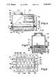
- FIG. 4is a side elevational view partially in cross-section of the thermal electric cooler shown in FIGS. 1 and 2.
- FIG. 5is an end elevational view in cross-section taken along the line 5--5 of FIG. 4.
- FIG. 6is a cross-sectional view of the thermal electric cooler shown in FIGS. 1 and 2 taken along the line 6--6 of FIG. 4.
- the thermal electric liquid cooling system of the present inventionconsists of a tank for containing the liquid.
- a cooling plateis secured to the tank and forms a part of the tank.
- the cooling plateis formed of a heat conductive material and has first and second surfaces with the first surface in contact with the liquid in the tank.
- a plurality of thermal electric modulesare in contact with the second surface of the cooling plate.
- a cooling manifoldis secured to the cooling plate and is in engagement with the thermal electric cooling devices and serves to sandwich the thermal electric cooling modules between the cooling plate and the cooling manifold.
- Meansis provided for supplying a liquid coolant to the cooling manifold to withdraw heat from the cooling manifold.
- the thermal electric cooling system 11 of the present invention as shown in FIG. 1consists of a thermal electric cooler 12 which is shown in detail in FIGS. 4, 5 and 6.
- the thermal electric cooler 12consists of an upper tank 16 and a lower tank 17.
- the upper tank 16is generally rectangular in configuration and is provided with spaced apart parallel side walls 18 and 19, and spaced apart end walls 21 and 22 which adjoin the side walls 18 and 19 at right angles thereto.
- a flange 24which is secured to the lower extremities of the side walls 18 and 19 and the end walls 21 and 22 and extend horizontally therefrom.
- the lower tank 17also has a rectangular configuration and is provided with spaced apart parallel side walls 26 and 27, and spaced apart parallel end walls 28 and 29 which adjoin the side walls 26 and 27 at right angles thereto. It is also provided with a bottom wall 31.
- a flange 32extends around the upper extremities of the side walls 26 and 27 and end walls 28 and 29 and extends at right angles or horizontally therefrom.
- a thermal electric unit or plate 36is provided which is formed of a suitable conducting metal such as aluminum which is generally planar and is provided with first and second planar parallel surfaces 37 and 38. The plate 36 has generally the same dimensions as the flanges 24 and 32.
- a gasket 41is disposed between the flange 24 and the second surface 38 of the plate 36 to form a fluid-tight seal between the plate 36 and the flange 24 and for the upper tank 16.
- the upper tank 16, the gasket 41, the thermal electric unit or plate 36 and lower tank 17are secured into a unitary assembly by bolts 42 extending through the flanges 24 and 32 and the gasket 41 and the plate 36.
- a plurality of spaced apart parallel vertically upstanding fins 46are mounted on the plate 36 and are also formed of a suitable conducting material as aluminum.
- the fins 46can be formed of separate elements and then bonded to the plate 36, or, alternatively, the plate 36 with the upstanding fins 46 can be formed integral in a suitable manner such as by forming both the plate and the fins from an aluminum extrusion.
- the fins 46extend upwardly into the upper tank 16 and are adapted to come into contact with any liquid placed in the upper tank 16.
- the fins 46 with the associated plate 36serve as a heat sink.
- the thermal electric unit 34also includes a plurality of spaced apart thermal electric cooler cells 48 of a suitable size, as for example approximately 11/4" by 11/4" with a thickness of approximately 1/8".
- These cells or modules 48are of a conventional type manufactured by Marlow Industries, Inc., at 10451 Vista Park Road, Dallas, Tex., 75232. As shown in FIG. 6, twelve of such cells or modules 48 have been provided and arranged with six in two spaced apart parallel rows on the bottom or first surface of the plate 37 and are held in intimate contact therewith and are sandwiched between the bottom or second surface 38 of plate 36 and the upper or first surface 51 of a water jacket or manifold 52.
- the water jacket or manifold 52is formed of a suitable conducting material such as aluminum and is secured to the plate 36 by suitable means such as screws 54.
- the manifold 52is provided with a serpentine flow passage 56 which extends through the manifold as shown in dotted lines in FIG. 6 and is in communication with an inlet fitting 57 and an outlet fitting 58 mounted on one end of the manifold facing the end wall 28 of the lower tank 17.
- the serpentine flow passageprovides spaced parallel passages 56a, 56b, 56c and 56d lying adjacent each of the two rows of thermal electric cells or modules 48 as shown particularly in FIG. 6.
- the passages 56a and 56bare interconnected by a passage 56e and passages 56c and 56d are interconnected by a passage 56f.
- Passages 56b and 56care interconnected by a U 59.
- the inlet and outlet fittings 57 and 58are connected to piping 60 and 61 for supplying a suitable cooling liquid such as water to the serpentine flow passage 56 within the manifold 52.
- An inlet fitting 63is provided on the front end wall 21 of the upper tank 16 and an outlet fitting 64 is provided in the side wall 19 of the upper tank 16.
- a large clean-out opening 66is also provided in the top wall 33 and has a removable threaded cap 67 mounted thereon.
- Another fitting 68is also provided in the top wall 23 and there is provided a valve (not shown) mounted therein to permit the bleeding of air into and out of the upper tank 16 as the same is being filled with liquid or liquid is being withdrawn therefrom.
- a rod-like or cylindrical cartridge electric heater 71is mounted in the end wall and is provided for heating the liquid in the upper tank 16 as hereinafter described.
- a temperature switch 72 and a liquid level float switch 73are also mounted in the end wall 22.
- a compartment 76is mounted on the end 22 of the upper tank 16 and is provided for making electrical connections to the heater 71, the temperature sensor 72 and the liquid level switch 73 as well as for making connections to the thermal electric unit 34 with the cells or modules 48 therein.
- the lines 59 and 61 connected to the manifold 52are connected to a heat exchanger and a city water supply in a conventional manner.
- the compartment 76is connected by a control cable 77 connector to a controller 78.
- the inlet fitting 63is connected by a line or conduit 81 to a fitting 82 provided on a wafer chuck 83.
- An outlet 64 on the wafer chuckis connected by a line 86 to the outlet 87 of a pump 88.
- Inlet 89 to the pump 81is connected by a line 91 to the outlet 64 on the upper tank 16.
- the operation and use of the system shown in FIG. 1may now be briefly described as follows. Let it be assumed that wafers (not shown) are transported from a hot zone onto the wafer chuck 83.
- the wafer chuckserves to cool the wafers down to a predetermined desired temperature plus or minus 1/10th of a degree.
- the upper tank 16is filled with the cooling liquid, as for example distilled water, which is cooled to a desired temperature by the thermal electric unit 34 under the control of the controller 78.
- the controller 78can be of a conventional type, as for example a proportional plus integral plus derivative type of controller. Such controller responds to the rate at which the measurement is changing even though the actual error is still small.
- thermal electric cells or modules 48are always operating under the same polarity so that the thermal electric cells or modules 48 are always cooling and are not used for heating. If heat is needed to maintain the desired temperature, the heat is supplied from the cartridge heater 71 to provide the constant temperature under the control of the controller 78. Since polarity is not reversed on the thermal electric cells or modules 48, improved reliability is obtained from the thermal electric cells or modules 48.
- FIG. 2Another system 101 shown in FIG. 2 utilizes the thermal electric cooler 12 for cooling a developer in a developer cooling tank 102 which is provided with a coil 103 which is helically wound into a cylindrical shape.
- the coil 103is connected to the lines 81 and 86 of a suitable size such as 1" through tees 104 to the cooler 12 through the pump 88 so that a cooling liquid is pumped through the coil 103.
- the developer to be cooledis supplied from a tank (not shown) to the coil 103 through a line 106 of a suitable size as for example 1/4" through a plug 107 mounted in one leg of the tee 104.
- the line 106extends through the coil 103 and is connected to a line 108 which exits through the other tee 104 and a plug 107 is provided therein and is connected to the wafer process station (not shown) for use therein.
- heat or coldcan be transferred from the liquid within the lines 81 and 86 under the control of the controller 78 for the thermal electric cooler 12 to cool or heat the developer flowing internally of lines 106 and 108 within the coil 103 in which the cooling liquid from the thermal electric cooler 12 is flowing. In this way, a developer can be maintained at a predetermined desired temperature.
- thermal electric coolers of the present inventionare ideally suited to a wide variety of systems because of their size, wide operating range, low power requirements and high reliability.
- the thermal electric coolers in the systems of the present inventionare solid state with no moving parts. Since there are no moving parts, extreme reliability is obtained which reduces downtime. They are environmentally more desirable because they do not use conventional refrigerants such as Freon and CFCs (chlorofluorocarbons). They also do not use corrosive liquids and gases. There are no compressor noises or particle generating fans.
- thermal electric coolers made in accordance with the present inventionhave had the ability to cool and heat the tank contents from 40° C. to 15° C. and keep a precise temperature control with a tolerance of plus or minus 0° C.
- the physical size for one coolerprovides a small footprint, as for example 101/2" wide, 16" long and 11" high.
Landscapes
- Engineering & Computer Science (AREA)
- Physics & Mathematics (AREA)
- Health & Medical Sciences (AREA)
- Thermal Sciences (AREA)
- General Engineering & Computer Science (AREA)
- Mechanical Engineering (AREA)
- Epidemiology (AREA)
- Atmospheric Sciences (AREA)
- Environmental & Geological Engineering (AREA)
- Combustion & Propulsion (AREA)
- Toxicology (AREA)
- General Physics & Mathematics (AREA)
- Life Sciences & Earth Sciences (AREA)
- Chemical & Material Sciences (AREA)
- Public Health (AREA)
- Heat-Exchange Devices With Radiators And Conduit Assemblies (AREA)
Abstract
Description
This invention relates to a thermal electric cooling system for liquids, and more particularly to such a system which is a solid-state product CFC free.
In U.S. Pat. No. 5,029,445 issued on Jul. 9, 1991 there is disclosed a thermal electric cooling system for liquids which incorporates muffin fans and a pump motor. It has been found in certain applications that the thermal electric cooling system disclosed in U.S. Pat. No. 5,029,445 is too bulky and is objectionable on some applications because of the fan noise and particle generation. There is therefore a need for a new and improved thermal electric cooling system.
In general, it is an object of the present invention to provide a thermal electric cooling system which is relatively compact and a method for operating the same.
Another object of the invention is to provide a system of the above character which is self-contained and can provide heating and chilling.
Another object of the invention is to provide a system of the above character which eliminates the need for muffin fans.
Another object of the invention is to provide a system of the above character in which the thermal electronics are utilized to transfer cooling to an internal heat exchanger.
Another object of the invention is to provide a system of the above character which does not generate particles.
Another object of the invention is to provide a system of the above character which can be utilized in Class 10 to Class 1 cleanrooms.
Another object of the invention is to provide a system of the above character in which heat is removed by water through a water jacket.
Another object of the invention is to provide a system of the above character which is reliable and efficient.
Additional objects and features of the invention will appear from the following description in which the preferred embodiments are set forth in conjunction with the accompanying drawings.
FIG. 1 is an isometric view of a thermal electric cooling system incorporating the present invention which is utilized for cooling a wafer chuck.
FIG. 2 is an isometric view of a system of the above character similar to FIG. 1 used for cooling developer.
FIG. 3 is an enlarged elevational view showing the tee-type connections shown in FIG. 2.
FIG. 4 is a side elevational view partially in cross-section of the thermal electric cooler shown in FIGS. 1 and 2.
FIG. 5 is an end elevational view in cross-section taken along theline 5--5 of FIG. 4.
FIG. 6 is a cross-sectional view of the thermal electric cooler shown in FIGS. 1 and 2 taken along theline 6--6 of FIG. 4.
In general the thermal electric liquid cooling system of the present invention consists of a tank for containing the liquid. A cooling plate is secured to the tank and forms a part of the tank. The cooling plate is formed of a heat conductive material and has first and second surfaces with the first surface in contact with the liquid in the tank. A plurality of thermal electric modules are in contact with the second surface of the cooling plate. A cooling manifold is secured to the cooling plate and is in engagement with the thermal electric cooling devices and serves to sandwich the thermal electric cooling modules between the cooling plate and the cooling manifold. Means is provided for supplying a liquid coolant to the cooling manifold to withdraw heat from the cooling manifold.
More in particular, the thermalelectric cooling system 11 of the present invention as shown in FIG. 1 consists of a thermalelectric cooler 12 which is shown in detail in FIGS. 4, 5 and 6. As shown therein, the thermalelectric cooler 12 consists of anupper tank 16 and alower tank 17. Theupper tank 16 is generally rectangular in configuration and is provided with spaced apartparallel side walls end walls side walls flange 24 which is secured to the lower extremities of theside walls end walls
Thelower tank 17 also has a rectangular configuration and is provided with spaced apartparallel side walls parallel end walls side walls flange 32 extends around the upper extremities of theside walls end walls plate 36 is provided which is formed of a suitable conducting metal such as aluminum which is generally planar and is provided with first and second planarparallel surfaces plate 36 has generally the same dimensions as theflanges gasket 41 is disposed between theflange 24 and thesecond surface 38 of theplate 36 to form a fluid-tight seal between theplate 36 and theflange 24 and for theupper tank 16. Theupper tank 16, thegasket 41, the thermal electric unit orplate 36 andlower tank 17 are secured into a unitary assembly bybolts 42 extending through theflanges gasket 41 and theplate 36.
A plurality of spaced apart parallel verticallyupstanding fins 46 are mounted on theplate 36 and are also formed of a suitable conducting material as aluminum. Thefins 46 can be formed of separate elements and then bonded to theplate 36, or, alternatively, theplate 36 with theupstanding fins 46 can be formed integral in a suitable manner such as by forming both the plate and the fins from an aluminum extrusion. As can be seen from FIG. 5, thefins 46 extend upwardly into theupper tank 16 and are adapted to come into contact with any liquid placed in theupper tank 16. Thus thefins 46 with the associatedplate 36 serve as a heat sink.
The thermal electric unit 34 also includes a plurality of spaced apart thermalelectric cooler cells 48 of a suitable size, as for example approximately 11/4" by 11/4" with a thickness of approximately 1/8". These cells ormodules 48 are of a conventional type manufactured by Marlow Industries, Inc., at 10451 Vista Park Road, Dallas, Tex., 75232. As shown in FIG. 6, twelve of such cells ormodules 48 have been provided and arranged with six in two spaced apart parallel rows on the bottom or first surface of theplate 37 and are held in intimate contact therewith and are sandwiched between the bottom orsecond surface 38 ofplate 36 and the upper or first surface 51 of a water jacket ormanifold 52.
The water jacket ormanifold 52 is formed of a suitable conducting material such as aluminum and is secured to theplate 36 by suitable means such asscrews 54. Themanifold 52 is provided with aserpentine flow passage 56 which extends through the manifold as shown in dotted lines in FIG. 6 and is in communication with an inlet fitting 57 and an outlet fitting 58 mounted on one end of the manifold facing theend wall 28 of thelower tank 17. The serpentine flow passage provides spacedparallel passages modules 48 as shown particularly in FIG. 6. Thepassages passage 56e andpassages passage 56f.Passages U 59. The inlet andoutlet fittings piping serpentine flow passage 56 within themanifold 52.
Aninlet fitting 63 is provided on thefront end wall 21 of theupper tank 16 and an outlet fitting 64 is provided in theside wall 19 of theupper tank 16. A large clean-out opening 66 is also provided in the top wall 33 and has a removable threadedcap 67 mounted thereon. Anotherfitting 68 is also provided in thetop wall 23 and there is provided a valve (not shown) mounted therein to permit the bleeding of air into and out of theupper tank 16 as the same is being filled with liquid or liquid is being withdrawn therefrom. A rod-like or cylindrical cartridge electric heater 71 is mounted in the end wall and is provided for heating the liquid in theupper tank 16 as hereinafter described. A temperature switch 72 and a liquidlevel float switch 73 are also mounted in theend wall 22.
Acompartment 76 is mounted on theend 22 of theupper tank 16 and is provided for making electrical connections to the heater 71, the temperature sensor 72 and theliquid level switch 73 as well as for making connections to the thermal electric unit 34 with the cells ormodules 48 therein.
As shown in FIG. 1, thelines manifold 52 are connected to a heat exchanger and a city water supply in a conventional manner. Thecompartment 76 is connected by acontrol cable 77 connector to acontroller 78.
Theinlet fitting 63 is connected by a line orconduit 81 to afitting 82 provided on awafer chuck 83. Anoutlet 64 on the wafer chuck is connected by aline 86 to theoutlet 87 of apump 88.Inlet 89 to thepump 81 is connected by aline 91 to theoutlet 64 on theupper tank 16.
The operation and use of the system shown in FIG. 1 may now be briefly described as follows. Let it be assumed that wafers (not shown) are transported from a hot zone onto thewafer chuck 83. The wafer chuck serves to cool the wafers down to a predetermined desired temperature plus or minus 1/10th of a degree. Theupper tank 16 is filled with the cooling liquid, as for example distilled water, which is cooled to a desired temperature by the thermal electric unit 34 under the control of thecontroller 78. Thecontroller 78 can be of a conventional type, as for example a proportional plus integral plus derivative type of controller. Such controller responds to the rate at which the measurement is changing even though the actual error is still small. When the temperature measurement starts to change, derivative action generates an immediate response proportional to its rate of change to provide a precision temperature control for the liquid within the thermalelectric cooler 12 and to thereby provide a liquid at a predetermined temperature to thewafer chuck 83. In the operation of the system, the thermal electric cells ormodules 48 are always operating under the same polarity so that the thermal electric cells ormodules 48 are always cooling and are not used for heating. If heat is needed to maintain the desired temperature, the heat is supplied from the cartridge heater 71 to provide the constant temperature under the control of thecontroller 78. Since polarity is not reversed on the thermal electric cells ormodules 48, improved reliability is obtained from the thermal electric cells ormodules 48.
Another system 101 shown in FIG. 2 utilizes the thermal electric cooler 12 for cooling a developer in a developer cooling tank 102 which is provided with acoil 103 which is helically wound into a cylindrical shape. Thecoil 103 is connected to thelines tees 104 to the cooler 12 through thepump 88 so that a cooling liquid is pumped through thecoil 103. The developer to be cooled is supplied from a tank (not shown) to thecoil 103 through a line 106 of a suitable size as for example 1/4" through aplug 107 mounted in one leg of thetee 104. The line 106 extends through thecoil 103 and is connected to aline 108 which exits through theother tee 104 and aplug 107 is provided therein and is connected to the wafer process station (not shown) for use therein. In this manner it can be seen that heat or cold can be transferred from the liquid within thelines controller 78 for the thermal electric cooler 12 to cool or heat the developer flowing internally oflines 106 and 108 within thecoil 103 in which the cooling liquid from the thermalelectric cooler 12 is flowing. In this way, a developer can be maintained at a predetermined desired temperature.
From the foregoing it can be seen that thermal electric coolers of the present invention are ideally suited to a wide variety of systems because of their size, wide operating range, low power requirements and high reliability. The thermal electric coolers in the systems of the present invention are solid state with no moving parts. Since there are no moving parts, extreme reliability is obtained which reduces downtime. They are environmentally more desirable because they do not use conventional refrigerants such as Freon and CFCs (chlorofluorocarbons). They also do not use corrosive liquids and gases. There are no compressor noises or particle generating fans.
By way of example, thermal electric coolers made in accordance with the present invention have had the ability to cool and heat the tank contents from 40° C. to 15° C. and keep a precise temperature control with a tolerance of plus or minus 0° C. The physical size for one cooler provides a small footprint, as for example 101/2" wide, 16" long and 11" high.
Claims (10)
1. In a thermal electric cooling system for a liquid, a horizontally disposed tank for containing the liquid, a horizontal cooling plate secured to the tank and forming a section of the bottom of the tank, said cooling plate being formed of a heat conductive material and having a first inwardly facing surface and a second downwardly facing surface and having the first upward facing surface in contact with the liquid in the tank, a plurality of thermal electric modules in contact with the second downwardly facing surface of the cooling plate, a cooling manifold having liquid flow passage therein secured to the cooling plate and in engagement with the thermal electric cooling devices and serving to sandwich the thermal electric cooling modules between the cooling plate and the cooling manifold and means for supplying a liquid coolant to the liquid flow passages of the cooling manifold to withdraw heat from the cooling manifold.
2. A system as in claim 1 together with a plurality of horizontally spaced apart vertically disposed parallel fins extending inwardly into the tank and in contact with the liquid and being in contact with the first surface of the cooling plate.
3. A system as in claim 1 wherein the cooling manifold is secured to the cooling plate by a plurality of screws.
4. A system as in claim 1 wherein said cooling plate forms the bottom wall of said tank and forms a liquid tight seal therewith.
5. A system as in claim 1 together with a wafer chuck and means for supplying a liquid from within the tank to the wafer chuck for maintaining the wafer chuck at a predetermined temperature.
6. A system as in claim 1 together with piping having a liquid therein to be cooled, means disposed in the vicinity of the piping for conveying a liquid from and to the tank and in contact with the piping so that energy is transferred from the liquid in the piping to the liquid conveyed to and from the tank.
7. A system as in claim 1 wherein said tank is provided with a removable fill cap together with a liquid level sensor disposed within the tank.
8. In a thermal electric cooling system for a liquid, a tank for containing the liquid, a cooling plate secured to the tank and forming a section of the bottom of the tank, said cooling plate being formed of a heat conductive material and having first and second surfaces and having the first surface in contact with the liquid in the tank, a plurality of thermal electric modules in contact with the second surface of the cooling plate, a cooling manifold secured to the cooling plate and in engagement with the thermal electric cooling devices and serving to sandwich the thermal electric cooling modules between the cooling plate and the cooling manifold and means for supplying a liquid coolant to the cooling manifold to withdraw heat from the cooling manifold, contact means connected to said thermal electric cooling devices for operating said thermal electric cooling devices continuously in a cooling mode and an electric heater mounted within the tank for supplying heat to the liquid in the tank when the liquid coolant drops below a predetermined temperature.
9. A system as in claim 8 together with a temperature sensor disposed within the tank controlling the operation of the electric heater.
10. A method for cooling a liquid in a tank having a cooling plate with thermal electric modules mounted thereon forming a section of the bottom of the tank and with an electric heater mounted in the tank comprising supplying electrical energy to one polarity of the thermal electric modules so that the thermal electric modules are always in the cooling mode and supplying electrical energy when needed to the electric heater to supply heat to maintain the liquid within the tank at a predetermined temperature.
Priority Applications (1)
| Application Number | Priority Date | Filing Date | Title |
|---|---|---|---|
| US07/727,986US5154661A (en) | 1991-07-10 | 1991-07-10 | Thermal electric cooling system and method |
Applications Claiming Priority (1)
| Application Number | Priority Date | Filing Date | Title |
|---|---|---|---|
| US07/727,986US5154661A (en) | 1991-07-10 | 1991-07-10 | Thermal electric cooling system and method |
Publications (1)
| Publication Number | Publication Date |
|---|---|
| US5154661Atrue US5154661A (en) | 1992-10-13 |
Family
ID=24924948
Family Applications (1)
| Application Number | Title | Priority Date | Filing Date |
|---|---|---|---|
| US07/727,986Expired - LifetimeUS5154661A (en) | 1991-07-10 | 1991-07-10 | Thermal electric cooling system and method |
Country Status (1)
| Country | Link |
|---|---|
| US (1) | US5154661A (en) |
Cited By (47)
| Publication number | Priority date | Publication date | Assignee | Title |
|---|---|---|---|---|
| US5450726A (en)* | 1993-07-16 | 1995-09-19 | Noah Precision, Inc. | Thermal electric air cooling apparatus and method |
| US5483800A (en)* | 1993-06-25 | 1996-01-16 | The United States Of America As Represented By The Administrator Of The National Aeronautics And Space Administration | Augmented thermal bus |
| US5514094A (en)* | 1994-02-14 | 1996-05-07 | The Anello Corporation | Cooling system for ocular infusion solution |
| US5522215A (en)* | 1993-10-18 | 1996-06-04 | Dainippon Screen Mfg. Co., Ltd. | Substrate cooling apparatus |
| US5544487A (en)* | 1991-01-15 | 1996-08-13 | Hydrocool Pty Ltd | Thermoelectric heat pump w/hot & cold liquid heat exchange circutis |
| WO1997000411A1 (en)* | 1995-06-16 | 1997-01-03 | The Technology Partnership Plc | Apparatus and method for cooling of liquids |
| US5590532A (en)* | 1994-02-04 | 1997-01-07 | Bunn-O-Matic Corporation | Solid state liquid temperature processor |
| US5613364A (en)* | 1995-10-06 | 1997-03-25 | Pou, Inc. | Compact replaceable temperature control module |
| US5640852A (en)* | 1995-10-06 | 1997-06-24 | Atlas; Boris | Compact thermal electric heat exchanger |
| US5653111A (en)* | 1993-07-07 | 1997-08-05 | Hydrocool Pty. Ltd. | Thermoelectric refrigeration with liquid heat exchange |
| US5689958A (en)* | 1996-09-27 | 1997-11-25 | The United States Of America As Represented By The Secretary Of The Air Force | High efficiency thermal electric cooler driver |
| US5711155A (en)* | 1995-12-19 | 1998-01-27 | Thermotek, Inc. | Temperature control system with thermal capacitor |
| US5737923A (en)* | 1995-10-17 | 1998-04-14 | Marlow Industries, Inc. | Thermoelectric device with evaporating/condensing heat exchanger |
| US5784890A (en)* | 1996-06-03 | 1998-07-28 | Polkinghorne; John D. | Compact thermoelectric refrigeration drive assembly |
| US5964092A (en)* | 1996-12-13 | 1999-10-12 | Nippon Sigmax, Co., Ltd. | Electronic cooling apparatus |
| US5996353A (en)* | 1998-05-21 | 1999-12-07 | Applied Materials, Inc. | Semiconductor processing system with a thermoelectric cooling/heating device |
| US6026896A (en)* | 1997-04-10 | 2000-02-22 | Applied Materials, Inc. | Temperature control system for semiconductor processing facilities |
| US6074363A (en)* | 1997-09-05 | 2000-06-13 | Respiratory Support Products, Inc. | Intravenous fluid heat exchanger |
| US6125635A (en)* | 1997-12-08 | 2000-10-03 | Seiko Seiki Kabushiki Kaisha | Temperature adjusting device |
| US6167883B1 (en) | 1998-01-23 | 2001-01-02 | Respiratory Support Products, Inc. | Medical air hose internal flow heater |
| US6293107B1 (en)* | 1996-11-08 | 2001-09-25 | Matsushita Refrigeration Company | Thermoelectric cooling system |
| EP1188998A1 (en)* | 2000-09-19 | 2002-03-20 | BSH Bosch und Siemens Hausgeräte GmbH | System and method for making ice pieces |
| EP1188996A1 (en)* | 2000-09-18 | 2002-03-20 | BSH Bosch und Siemens Hausgeräte GmbH | System and method for lowering a fluid temperature |
| EP1188997A1 (en)* | 2000-09-19 | 2002-03-20 | BSH Bosch und Siemens Hausgeräte GmbH | System and method for making ice pieces |
| US6502405B1 (en)* | 2001-10-19 | 2003-01-07 | John Van Winkle | Fluid heat exchanger assembly |
| US6508062B2 (en) | 2001-01-31 | 2003-01-21 | Applied Materials, Inc. | Thermal exchanger for a wafer chuck |
| US6641556B1 (en) | 1999-07-06 | 2003-11-04 | Respiratory Support Products, Inc. | Intravenous fluid heating system |
| US20040025516A1 (en)* | 2002-08-09 | 2004-02-12 | John Van Winkle | Double closed loop thermoelectric heat exchanger |
| US20040134932A1 (en)* | 2002-10-23 | 2004-07-15 | Lobdell Vincent G. | Beverage dispenser |
| US20050059238A1 (en)* | 2003-09-12 | 2005-03-17 | International Business Machines Corporation | Cooling system for a semiconductor device and method of fabricating same |
| US20060075758A1 (en)* | 2004-10-07 | 2006-04-13 | Tigerone Development, Llc; | Air-conditioning and heating system utilizing thermo-electric solid state devices |
| US7064036B2 (en) | 2001-04-27 | 2006-06-20 | Micron Technology, Inc. | Dual-gate transistor device and method of forming a dual-gate transistor device |
| US20070175225A1 (en)* | 2006-02-02 | 2007-08-02 | Amit Bahat | Temperature controlling device |
| US7278269B2 (en) | 2005-11-09 | 2007-10-09 | Emerson Climate Technologies, Inc. | Refrigeration system including thermoelectric module |
| US20080006037A1 (en)* | 2001-12-26 | 2008-01-10 | Coolit Systems Inc. | Computer cooling apparatus |
| US20080016881A1 (en)* | 2006-06-28 | 2008-01-24 | Chris Steffensen | Apparatus for heating and cooling at food serving stations |
| US20080161890A1 (en)* | 2007-01-03 | 2008-07-03 | Boston Scientific Scimed, Inc. | Methods, systems, and apparatuses for protecting esophageal tissue during ablation |
| WO2008061726A3 (en)* | 2006-11-21 | 2009-01-15 | Eugster Frismag Ag | Heat exchanger for cooling or heating a fluid, coolant circuit and method for cooling or heating a working fluid or a heat exchanger |
| US20090229274A1 (en)* | 2008-03-13 | 2009-09-17 | Andre Boulay | Thermoelectric retrofit unit for a liquid recipient |
| US7752852B2 (en) | 2005-11-09 | 2010-07-13 | Emerson Climate Technologies, Inc. | Vapor compression circuit and method including a thermoelectric device |
| RU2571165C1 (en)* | 2014-08-01 | 2015-12-20 | Станислав Святославович Сагаков | Method of liquid temperature measurements |
| US20160090798A1 (en)* | 2013-05-15 | 2016-03-31 | M-I L.L.C. | Modular Waste Processing System |
| CN110081634A (en)* | 2019-03-30 | 2019-08-02 | 保定市桥与果新材料科技有限公司 | A kind of refrigerating device for materials with circulation air feed function |
| US10405650B2 (en) | 2014-01-16 | 2019-09-10 | Bi-Polar Holdings Company, LLC | Heating and cooling system for a food storage cabinet |
| US10443906B2 (en)* | 2015-10-21 | 2019-10-15 | Andor Technology Limited | Heat pump system |
| US11045857B2 (en)* | 2018-05-23 | 2021-06-29 | Pride Engineering, Llc | Fluid-cooled ToolPack |
| US11607036B2 (en) | 2016-07-12 | 2023-03-21 | Bi-Polar Holding Company LLC | Food service apparatus with peltier heating and cooling systems |
Citations (11)
| Publication number | Priority date | Publication date | Assignee | Title |
|---|---|---|---|---|
| US2837899A (en)* | 1954-10-13 | 1958-06-10 | Rca Corp | Thermoelectric refrigerator |
| US2970450A (en)* | 1958-04-28 | 1961-02-07 | Whirlpool Co | Refrigerating apparatus including warming means |
| US3008300A (en)* | 1959-04-09 | 1961-11-14 | Carrier Corp | Thermoelectric apparatus for heating or cooling of fluids |
| US3139734A (en)* | 1961-03-16 | 1964-07-07 | Kuckens Alexander | Method and means for mounting and controlling peltier elements |
| US3178895A (en)* | 1963-12-20 | 1965-04-20 | Westinghouse Electric Corp | Thermoelectric apparatus |
| US4593529A (en)* | 1984-12-03 | 1986-06-10 | Birochik Valentine L | Method and apparatus for controlling the temperature and pressure of confined substances |
| US4829771A (en)* | 1988-03-24 | 1989-05-16 | Koslow Technologies Corporation | Thermoelectric cooling device |
| US4833888A (en)* | 1987-01-29 | 1989-05-30 | James M. Kerner | Thermoelectric heating and/or cooling system using liquid for heat exchange |
| US4977953A (en)* | 1988-03-31 | 1990-12-18 | Kabushiki Kaisha Toshiba | Latent heat regenerating apparatus |
| US4989626A (en)* | 1988-11-11 | 1991-02-05 | Hitachi, Ltd. | Apparatus for and method of controlling the opening and closing of channel for liquid |
| US5063582A (en)* | 1988-09-02 | 1991-11-05 | Canon Kabushiki Kaisha | Liquid cooled x-ray lithographic exposure apparatus |
- 1991
- 1991-07-10USUS07/727,986patent/US5154661A/ennot_activeExpired - Lifetime
Patent Citations (11)
| Publication number | Priority date | Publication date | Assignee | Title |
|---|---|---|---|---|
| US2837899A (en)* | 1954-10-13 | 1958-06-10 | Rca Corp | Thermoelectric refrigerator |
| US2970450A (en)* | 1958-04-28 | 1961-02-07 | Whirlpool Co | Refrigerating apparatus including warming means |
| US3008300A (en)* | 1959-04-09 | 1961-11-14 | Carrier Corp | Thermoelectric apparatus for heating or cooling of fluids |
| US3139734A (en)* | 1961-03-16 | 1964-07-07 | Kuckens Alexander | Method and means for mounting and controlling peltier elements |
| US3178895A (en)* | 1963-12-20 | 1965-04-20 | Westinghouse Electric Corp | Thermoelectric apparatus |
| US4593529A (en)* | 1984-12-03 | 1986-06-10 | Birochik Valentine L | Method and apparatus for controlling the temperature and pressure of confined substances |
| US4833888A (en)* | 1987-01-29 | 1989-05-30 | James M. Kerner | Thermoelectric heating and/or cooling system using liquid for heat exchange |
| US4829771A (en)* | 1988-03-24 | 1989-05-16 | Koslow Technologies Corporation | Thermoelectric cooling device |
| US4977953A (en)* | 1988-03-31 | 1990-12-18 | Kabushiki Kaisha Toshiba | Latent heat regenerating apparatus |
| US5063582A (en)* | 1988-09-02 | 1991-11-05 | Canon Kabushiki Kaisha | Liquid cooled x-ray lithographic exposure apparatus |
| US4989626A (en)* | 1988-11-11 | 1991-02-05 | Hitachi, Ltd. | Apparatus for and method of controlling the opening and closing of channel for liquid |
Cited By (60)
| Publication number | Priority date | Publication date | Assignee | Title |
|---|---|---|---|---|
| US5544487A (en)* | 1991-01-15 | 1996-08-13 | Hydrocool Pty Ltd | Thermoelectric heat pump w/hot & cold liquid heat exchange circutis |
| US5483800A (en)* | 1993-06-25 | 1996-01-16 | The United States Of America As Represented By The Administrator Of The National Aeronautics And Space Administration | Augmented thermal bus |
| US5653111A (en)* | 1993-07-07 | 1997-08-05 | Hydrocool Pty. Ltd. | Thermoelectric refrigeration with liquid heat exchange |
| US5450726A (en)* | 1993-07-16 | 1995-09-19 | Noah Precision, Inc. | Thermal electric air cooling apparatus and method |
| US5522215A (en)* | 1993-10-18 | 1996-06-04 | Dainippon Screen Mfg. Co., Ltd. | Substrate cooling apparatus |
| US5590532A (en)* | 1994-02-04 | 1997-01-07 | Bunn-O-Matic Corporation | Solid state liquid temperature processor |
| US5514094A (en)* | 1994-02-14 | 1996-05-07 | The Anello Corporation | Cooling system for ocular infusion solution |
| WO1997000411A1 (en)* | 1995-06-16 | 1997-01-03 | The Technology Partnership Plc | Apparatus and method for cooling of liquids |
| US5918468A (en)* | 1995-06-16 | 1999-07-06 | Ttp Group Plc | Apparatus and method for cooling of liquids |
| WO1998043026A1 (en)* | 1995-10-06 | 1998-10-01 | Pou, Inc. | Compact replaceable temperature control module |
| US5640852A (en)* | 1995-10-06 | 1997-06-24 | Atlas; Boris | Compact thermal electric heat exchanger |
| US5613364A (en)* | 1995-10-06 | 1997-03-25 | Pou, Inc. | Compact replaceable temperature control module |
| US6003319A (en)* | 1995-10-17 | 1999-12-21 | Marlow Industries, Inc. | Thermoelectric refrigerator with evaporating/condensing heat exchanger |
| US5737923A (en)* | 1995-10-17 | 1998-04-14 | Marlow Industries, Inc. | Thermoelectric device with evaporating/condensing heat exchanger |
| US5711155A (en)* | 1995-12-19 | 1998-01-27 | Thermotek, Inc. | Temperature control system with thermal capacitor |
| US5784890A (en)* | 1996-06-03 | 1998-07-28 | Polkinghorne; John D. | Compact thermoelectric refrigeration drive assembly |
| US5689958A (en)* | 1996-09-27 | 1997-11-25 | The United States Of America As Represented By The Secretary Of The Air Force | High efficiency thermal electric cooler driver |
| EP0949463A4 (en)* | 1996-11-08 | 2002-08-14 | Matsushita Refrigeration | Thermoelectric cooling system |
| US6293107B1 (en)* | 1996-11-08 | 2001-09-25 | Matsushita Refrigeration Company | Thermoelectric cooling system |
| US5964092A (en)* | 1996-12-13 | 1999-10-12 | Nippon Sigmax, Co., Ltd. | Electronic cooling apparatus |
| US6026896A (en)* | 1997-04-10 | 2000-02-22 | Applied Materials, Inc. | Temperature control system for semiconductor processing facilities |
| US6074363A (en)* | 1997-09-05 | 2000-06-13 | Respiratory Support Products, Inc. | Intravenous fluid heat exchanger |
| US6125635A (en)* | 1997-12-08 | 2000-10-03 | Seiko Seiki Kabushiki Kaisha | Temperature adjusting device |
| US6167883B1 (en) | 1998-01-23 | 2001-01-02 | Respiratory Support Products, Inc. | Medical air hose internal flow heater |
| US5996353A (en)* | 1998-05-21 | 1999-12-07 | Applied Materials, Inc. | Semiconductor processing system with a thermoelectric cooling/heating device |
| US6641556B1 (en) | 1999-07-06 | 2003-11-04 | Respiratory Support Products, Inc. | Intravenous fluid heating system |
| EP1188996A1 (en)* | 2000-09-18 | 2002-03-20 | BSH Bosch und Siemens Hausgeräte GmbH | System and method for lowering a fluid temperature |
| EP1188997A1 (en)* | 2000-09-19 | 2002-03-20 | BSH Bosch und Siemens Hausgeräte GmbH | System and method for making ice pieces |
| EP1188998A1 (en)* | 2000-09-19 | 2002-03-20 | BSH Bosch und Siemens Hausgeräte GmbH | System and method for making ice pieces |
| US6508062B2 (en) | 2001-01-31 | 2003-01-21 | Applied Materials, Inc. | Thermal exchanger for a wafer chuck |
| US7064036B2 (en) | 2001-04-27 | 2006-06-20 | Micron Technology, Inc. | Dual-gate transistor device and method of forming a dual-gate transistor device |
| US6502405B1 (en)* | 2001-10-19 | 2003-01-07 | John Van Winkle | Fluid heat exchanger assembly |
| WO2003036192A1 (en)* | 2001-10-19 | 2003-05-01 | John Van Winkle | Fluid heat exchanger assembly |
| US20080006037A1 (en)* | 2001-12-26 | 2008-01-10 | Coolit Systems Inc. | Computer cooling apparatus |
| US20040025516A1 (en)* | 2002-08-09 | 2004-02-12 | John Van Winkle | Double closed loop thermoelectric heat exchanger |
| US20040134932A1 (en)* | 2002-10-23 | 2004-07-15 | Lobdell Vincent G. | Beverage dispenser |
| US20050059238A1 (en)* | 2003-09-12 | 2005-03-17 | International Business Machines Corporation | Cooling system for a semiconductor device and method of fabricating same |
| US7029951B2 (en) | 2003-09-12 | 2006-04-18 | International Business Machines Corporation | Cooling system for a semiconductor device and method of fabricating same |
| US20060075758A1 (en)* | 2004-10-07 | 2006-04-13 | Tigerone Development, Llc; | Air-conditioning and heating system utilizing thermo-electric solid state devices |
| US7866164B2 (en) | 2004-10-07 | 2011-01-11 | Tac Unit, Llc | Cooling and heating systems and methods utilizing thermo-electric devices |
| US8307663B2 (en) | 2005-11-09 | 2012-11-13 | Emerson Climate Technologies, Inc. | Vapor compression circuit and method including a thermoelectric device |
| US7278269B2 (en) | 2005-11-09 | 2007-10-09 | Emerson Climate Technologies, Inc. | Refrigeration system including thermoelectric module |
| US7284379B2 (en) | 2005-11-09 | 2007-10-23 | Emerson Climate Technologies, Inc. | Refrigeration system including thermoelectric module |
| US7310953B2 (en) | 2005-11-09 | 2007-12-25 | Emerson Climate Technologies, Inc. | Refrigeration system including thermoelectric module |
| US20110120145A1 (en)* | 2005-11-09 | 2011-05-26 | Masao Akei | Vapor Compression Circuit and Method Including A Thermoelectric Device |
| US7752852B2 (en) | 2005-11-09 | 2010-07-13 | Emerson Climate Technologies, Inc. | Vapor compression circuit and method including a thermoelectric device |
| US20070175225A1 (en)* | 2006-02-02 | 2007-08-02 | Amit Bahat | Temperature controlling device |
| US20080016881A1 (en)* | 2006-06-28 | 2008-01-24 | Chris Steffensen | Apparatus for heating and cooling at food serving stations |
| US7665311B2 (en)* | 2006-06-28 | 2010-02-23 | Chris Steffensen | Apparatus for heating and cooling at food serving stations |
| WO2008061726A3 (en)* | 2006-11-21 | 2009-01-15 | Eugster Frismag Ag | Heat exchanger for cooling or heating a fluid, coolant circuit and method for cooling or heating a working fluid or a heat exchanger |
| US20080161890A1 (en)* | 2007-01-03 | 2008-07-03 | Boston Scientific Scimed, Inc. | Methods, systems, and apparatuses for protecting esophageal tissue during ablation |
| US20090229274A1 (en)* | 2008-03-13 | 2009-09-17 | Andre Boulay | Thermoelectric retrofit unit for a liquid recipient |
| US20160090798A1 (en)* | 2013-05-15 | 2016-03-31 | M-I L.L.C. | Modular Waste Processing System |
| US10145191B2 (en)* | 2013-05-15 | 2018-12-04 | M-I Drilling Fluids Uk Ltd | Modular waste processing system |
| US10405650B2 (en) | 2014-01-16 | 2019-09-10 | Bi-Polar Holdings Company, LLC | Heating and cooling system for a food storage cabinet |
| RU2571165C1 (en)* | 2014-08-01 | 2015-12-20 | Станислав Святославович Сагаков | Method of liquid temperature measurements |
| US10443906B2 (en)* | 2015-10-21 | 2019-10-15 | Andor Technology Limited | Heat pump system |
| US11607036B2 (en) | 2016-07-12 | 2023-03-21 | Bi-Polar Holding Company LLC | Food service apparatus with peltier heating and cooling systems |
| US11045857B2 (en)* | 2018-05-23 | 2021-06-29 | Pride Engineering, Llc | Fluid-cooled ToolPack |
| CN110081634A (en)* | 2019-03-30 | 2019-08-02 | 保定市桥与果新材料科技有限公司 | A kind of refrigerating device for materials with circulation air feed function |
Similar Documents
| Publication | Publication Date | Title |
|---|---|---|
| US5154661A (en) | Thermal electric cooling system and method | |
| EP0338283B1 (en) | Thermoelectric cooling device | |
| US5367879A (en) | Modular thermoelectric assembly | |
| US6463743B1 (en) | Modular thermoelectric unit and cooling system using same | |
| US20030016498A1 (en) | Cooling apparatus for electronic unit | |
| US7322400B2 (en) | Cooling apparatus having low profile extrusion | |
| US3100969A (en) | Thermoelectric refrigeration | |
| US7650757B2 (en) | Thermoelectric heat transfer system | |
| WO2003012357A2 (en) | Heat exchanger assembly and heat exchange manifold | |
| JPH1172276A (en) | Thermoelectric system | |
| US2931188A (en) | Fluid cooling apparatus | |
| US20030188540A1 (en) | Cooling system for a beverage dispenser | |
| CN210220285U (en) | Over-temperature protection device of heat exchanger | |
| US4453503A (en) | Cooling device | |
| JPH11173701A (en) | Temp. regulator | |
| US20060075761A1 (en) | Apparatus for cooled or heated on demand drinking water and process for making same | |
| US7044213B2 (en) | Constant temperature refrigeration system for extensive temperature range application and control method thereof | |
| JP2001082828A (en) | Heat exchanger and heat carrier supply system | |
| JPH0317443A (en) | Heat exchanger | |
| US5450726A (en) | Thermal electric air cooling apparatus and method | |
| US7481375B2 (en) | Apparatuses and methods for controlling the temperature of a process fluid | |
| CN210000051U (en) | novel cold and hot air conditioner for vehicle and assembly thereof | |
| JP3542548B2 (en) | Fluid temperature controller | |
| RU31637U1 (en) | Device for regulating the temperature of milk during its transportation | |
| JP3641670B2 (en) | Cooler |
Legal Events
| Date | Code | Title | Description |
|---|---|---|---|
| AS | Assignment | Owner name:NOAH PRECISION, INC., A CORP. OF CA, CALIFORNIA Free format text:ASSIGNMENT OF ASSIGNORS INTEREST.;ASSIGNOR:HIGGINS, ROBERT W.;REEL/FRAME:005783/0665 Effective date:19910710 | |
| STCF | Information on status: patent grant | Free format text:PATENTED CASE | |
| FPAY | Fee payment | Year of fee payment:4 | |
| FPAY | Fee payment | Year of fee payment:8 | |
| REMI | Maintenance fee reminder mailed | ||
| FPAY | Fee payment | Year of fee payment:12 | |
| SULP | Surcharge for late payment | Year of fee payment:11 | |
| AS | Assignment | Owner name:ADVANCED ENERGY INDUSTRIES, INC., COLORADO Free format text:AGREEMENT AND PLAN OF REORGANIZATION;ASSIGNORS:NOAH PRECISION, INC.;NOAH HOLDINGS, INC.;REEL/FRAME:015259/0854 Effective date:20000405 |