US5154645A - Bulb socket - Google Patents
Bulb socketDownload PDFInfo
- Publication number
- US5154645A US5154645AUS07/665,845US66584591AUS5154645AUS 5154645 AUS5154645 AUS 5154645AUS 66584591 AUS66584591 AUS 66584591AUS 5154645 AUS5154645 AUS 5154645A
- Authority
- US
- United States
- Prior art keywords
- bulb
- socket
- connector
- socket body
- earth terminal
- Prior art date
- Legal status (The legal status is an assumption and is not a legal conclusion. Google has not performed a legal analysis and makes no representation as to the accuracy of the status listed.)
- Expired - Lifetime
Links
- 238000003780insertionMethods0.000claimsabstractdescription24
- 230000037431insertionEffects0.000claimsabstractdescription24
- 230000002093peripheral effectEffects0.000claimsabstractdescription14
- 238000001746injection mouldingMethods0.000claimsabstractdescription8
- 239000011347resinSubstances0.000claimsdescription11
- 229920005989resinPolymers0.000claimsdescription11
- 238000005452bendingMethods0.000claimsdescription2
- 239000002184metalSubstances0.000claimsdescription2
- 238000007789sealingMethods0.000claims1
- 238000000465mouldingMethods0.000description16
- 238000000034methodMethods0.000description4
- 238000010276constructionMethods0.000description1
- 230000003247decreasing effectEffects0.000description1
- 230000007812deficiencyEffects0.000description1
- WABPQHHGFIMREM-UHFFFAOYSA-Nlead(0)Chemical compound[Pb]WABPQHHGFIMREM-UHFFFAOYSA-N0.000description1
- 238000004519manufacturing processMethods0.000description1
Images


Classifications
- H—ELECTRICITY
- H01—ELECTRIC ELEMENTS
- H01R—ELECTRICALLY-CONDUCTIVE CONNECTIONS; STRUCTURAL ASSOCIATIONS OF A PLURALITY OF MUTUALLY-INSULATED ELECTRICAL CONNECTING ELEMENTS; COUPLING DEVICES; CURRENT COLLECTORS
- H01R43/00—Apparatus or processes specially adapted for manufacturing, assembling, maintaining, or repairing of line connectors or current collectors or for joining electric conductors
- H01R43/20—Apparatus or processes specially adapted for manufacturing, assembling, maintaining, or repairing of line connectors or current collectors or for joining electric conductors for assembling or disassembling contact members with insulating base, case or sleeve
- H01R43/24—Assembling by moulding on contact members
- H—ELECTRICITY
- H01—ELECTRIC ELEMENTS
- H01R—ELECTRICALLY-CONDUCTIVE CONNECTIONS; STRUCTURAL ASSOCIATIONS OF A PLURALITY OF MUTUALLY-INSULATED ELECTRICAL CONNECTING ELEMENTS; COUPLING DEVICES; CURRENT COLLECTORS
- H01R33/00—Coupling devices specially adapted for supporting apparatus and having one part acting as a holder providing support and electrical connection via a counterpart which is structurally associated with the apparatus, e.g. lamp holders; Separate parts thereof
- H01R33/05—Two-pole devices
- H01R33/46—Two-pole devices for bayonet type base
- H01R33/465—Two-pole devices for bayonet type base secured to structure or printed circuit board
Definitions
- the present inventionrelates generally to a bulb socket and method for molding same for use in a motor vehicle lamp or the like, and more particularly to a bulb socket of a so-called direct-connecting type having a bulb insertion portion and a connector insertion portion and in which a positive terminal and an earth terminal are partially embedded in the body integrally as the body of the socket is molded.
- a bulb contact portion of the earth terminalis liable to be deformed by the pressure of the molten resin during the molding thereby decreasing the yield rate of products, because the contact portion of the earth terminal is particularly thin, flattened in shape, and extends a long distance to an upper portion.
- bulb socketwhich, according to the invention, is provided with a positive terminal and an earth terminal are embedded in a body of a socket having a bulb insertion hole, a connector connecting portion, and a die insertion space formed between a peripheral wall of the socket body constituting the bulb insertion hole and a bulb contact portion of the earth terminal.
- FIG. 1is a plan view of a valve socket according to a first embodiment of the present invention
- FIG. 2is a cross-sectional view taken along the line II--II of FIG. 1 with a bulb and a connector;
- FIG. 3is a cross-sectional view taken along the line III--III of FIG. 1 with the bulb;
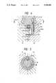
- FIG. 4is a cross-sectional view showing a die for molding the bulb socket of the first embodiment of the present invention
- FIG. 5is a cross-sectional view taken along the line V--V of FIG. 4;
- FIG. 6is a plan view of a valve socket according to the second embodiment of the present invention.
- FIG. 7is cross-sectional view showing a die for molding a bulb socket of the second embodiment of the invention.
- FIG. 8is a cross-sectional view taken along the line VII--VII of FIG. 7.
- FIGS. 1-5show a first embodiment of the present socket according to a first embodiment of the present invention
- FIG. 2is a cross-sectional view taken along the line II--II of FIG. 1 with a bulb and a connector
- FIG. 3is a cross-sectional view taken along the line III--III of FIG. 1 with the bulb
- FIG. 4is a cross-sectional view showing a die for molding the bulb socket of the first embodiment of the present invention
- FIG. 5is a cross-sectional view taken along the line V--V of FIG. 4.
- a socket body A formed of a resinhas a bulb insertion hole 1 for fitting therein a bulb B (double-dashed line), and a connector connecting hole 2 for fitting therein a connector F (double-dashed line).
- the direction of the bulb insertion hole 1 and that of the connector connecting hole 2are substantially perpendicular and thus the socket body A is integrally and generally L-shaped.
- the bulb insertion hole 1is provided with an inner peripheral wall 11 for directly supporting the bulb B, and an outer peripheral wall 12 for mounting to a socket-mounting opening of a lamp assembly.
- a J-shaped slot 14 for retaining a mounting pin B 1 of the bulb Bis formed on an inner surface 11a of the inner peripheral wall 11.
- a bayonet 15 and a flange 16 adapted to engage with the socket mounting member of the lamp assemblyare formed integrally with the outer peripheral wall 12 and project therefrom.
- a seal ring 30 formed of rubbermay be fitted on the flange 16 to thereby obtain a sealability between the socket body and the lamp assembly.
- An engaging hole 21 for engaging with the connector F by an integral engaging projection 22is provided on the bottom portion of the connector connecting hole 2.
- a positive terminal C and an earth terminal Dare embedded integrally in the socket body A by injection molding, these two terminals C and D extending from the bulb insertion hole 1 to the connector connecting hole 2 side. Both a bulb contact portion 3 of the positive terminal C and a bulb contact portion 4 of the earth terminal D are disposed in the interior of the bulb insertion hole 1. On the other hand, a connector contact portion 5 of the positive terminal C and a connector contact portion 6 of the earth terminal D are disposed in the interior of the connector connection hole 2.
- the bulb socketis for use with a single filament-type bulb having one positive terminal C
- the inventionmay similarly be applied to the type of bulb socket for use with a double filament-type bulb having two positive terminals.
- Each of the positive terminal C and the earth terminal Dis formed of a single electrically-conductive metal sheet by bending same. That is, the positive terminal C is unitary provided with the bulb contact portion 3 for electrically connecting to the bulb B and the connector contact portion 5 for electrically connecting to the connector F. Similarly, the earth terminal D is unitary provided with the bulb contact portion 4 for electrically connecting to the bulb B and the connector contact portion 6 for electrically connecting to the connector F.
- Each of the positive terminal C and the earth terminal Dis integrally embedded into the socket body by an injection molding in such a manner that the bulb contact portion 3 of the positive terminal C is disposed at substantially the bottom center of the bulb insertion hole 1. Further, at least a part of the bulb contact portion 4 of the earth terminal D is disposed between the inner peripheral wall 11 and the outer peripheral wall 12 of the bulb insertion hole 1. As shown in FIG. 4, a space portion 7 for receiving a die E 13 for molding the socket body A as shown in FIG. 2 is formed between the bulb contact portion 4 of the earth terminal D and the outer peripheral wall 12.
- the bulb contact portion 3 of the positive terminal Cis inserted into a bottom recess E 11 of a core die E 1 (one of dies E 1 , E 2 and E 3 for molding the socket body A). Further, the bulb contact portion 4 of the earth terminal D is inserted into a side recess E 12 of the core die E 1 . The bulb contact portion 4 of the earth terminal D comes into abutment against the inner wall of the side recess E 12 of the core die E 1 as shown in FIGS. 4 and 5.
- the die E 2 and the die E 3are mated together with the core die E 1 interposed therebetween, thereby forming a cavity 8 into which a molten resin is injected to thereby fill the cavity 8.
- the bulb insertion hole 1 and the connector connection hole 2 of the socket body Aare formed, and the positive terminal C and the earth terminal D are integrally provided in the socket body A, and that portion corresponding to the outer wall portion E 13 of the side recess E 12 in the core die E 1 forms the space portion 7.
- the earth terminal Dis not deformed by the pressure of the resin since the terminal D is fully supported by a die E 13 at a back thereof.
- FIGS. 6-8show a second embodiment of the invention.
- FIG. 6is a plan view of a valve socket according to the second embodiment of the present invention
- FIG. 7is cross-sectional view showing a die for molding a bulb socket of the second embodiment of the invention
- FIG. 8is a cross-sectional view taken along the line VII--VII of FIG. 7.
- same parts and components as that of the first embodimentare designated by the same reference numerals.
- a die E 113supports the earth terminal D at an upper part and a center part of the terminal D so that the molten resin injected into the cavity 8 embeds the terminal D surrounding both edges thereof as shown in FIG. 6.
- an outer wall portion E 113 of the side recess E 12 in the core die E 1partially but directly supports the bulb contact portion 4 of the earth terminal D. Therefore, the bulb socket body A is provided with a space portion 107 shown in FIG. 6 formed between the bulb contact portion 4 and the outer wall 12 of the socket body A.
- the bulb contact portion of the earth terminalcan directly be supported and reinforced by the socket body-forming die itself. Therefore, even when the bulb contact portion of the earth terminal receives the resin pressure during the molding, the bulb contact portion will not be deformed and, therefore, the yield rate of products can greatly be increased.
Landscapes
- Engineering & Computer Science (AREA)
- Manufacturing & Machinery (AREA)
- Connecting Device With Holders (AREA)
Abstract
Description
Claims (8)
Applications Claiming Priority (2)
| Application Number | Priority Date | Filing Date | Title |
|---|---|---|---|
| JP1990024722UJP2533799Y2 (en) | 1990-03-12 | 1990-03-12 | Valve socket |
| JP2-24722[U] | 1990-03-12 |
Publications (1)
| Publication Number | Publication Date |
|---|---|
| US5154645Atrue US5154645A (en) | 1992-10-13 |
Family
ID=12146054
Family Applications (1)
| Application Number | Title | Priority Date | Filing Date |
|---|---|---|---|
| US07/665,845Expired - LifetimeUS5154645A (en) | 1990-03-12 | 1991-03-07 | Bulb socket |
Country Status (2)
| Country | Link |
|---|---|
| US (1) | US5154645A (en) |
| JP (1) | JP2533799Y2 (en) |
Cited By (11)
| Publication number | Priority date | Publication date | Assignee | Title |
|---|---|---|---|---|
| US5282756A (en)* | 1992-12-11 | 1994-02-01 | General Electric Company | Electrical lamp base and socket assembly |
| US5320553A (en)* | 1991-06-11 | 1994-06-14 | Sumitomo Wiring Systems, Ltd. | Bulb socket and terminal installed thereon |
| US5507670A (en)* | 1993-09-07 | 1996-04-16 | Sumitomo Wiring Systems, Ltd. | Bulb socket |
| EP0650231A3 (en)* | 1993-10-26 | 1997-01-02 | Sumitomo Wiring Systems | Bulb socket. |
| EP0740375A3 (en)* | 1995-04-28 | 1997-11-12 | Sumitomo Wiring Systems, Ltd. | Bulb socket and the manufacturing method of the same |
| EP0809329A1 (en)* | 1996-05-22 | 1997-11-26 | Socop SA | Curved support for a lamp for electrical connection formed by casting |
| US5749743A (en)* | 1995-01-14 | 1998-05-12 | Koito Manufacturing Co., Ltd. | Bulb socket for vehicular lamp |
| US6017235A (en)* | 1996-07-29 | 2000-01-25 | Koito Manufacturing Co., Ltd, | Bulb socket |
| US6109953A (en)* | 1998-02-02 | 2000-08-29 | Koito Manufacturing Co., Ltd. | Socket plug |
| US6616474B2 (en)* | 2000-11-17 | 2003-09-09 | Koito Manufacturing Co., Ltd. | Bulb socket |
| US20050181678A1 (en)* | 2004-02-12 | 2005-08-18 | Patent-Treuhand-Gesellschaft Fur Elektrische Gluhlampen Mbh | Base for a headlight lamp and headlight lamp |
Families Citing this family (2)
| Publication number | Priority date | Publication date | Assignee | Title |
|---|---|---|---|---|
| JP4942460B2 (en)* | 2006-10-23 | 2012-05-30 | 浜井電球工業株式会社 | Large interior-lit signboard |
| JP4902630B2 (en)* | 2007-12-07 | 2012-03-21 | 株式会社マブチ照明製作所 | Light guide type lighting fixture |
Citations (5)
| Publication number | Priority date | Publication date | Assignee | Title |
|---|---|---|---|---|
| DE2361314A1 (en)* | 1972-12-13 | 1974-06-27 | Carello & C Spa Fausto | LAMP SOCKET FOR VEHICLE LIGHTS |
| US4588248A (en)* | 1985-01-30 | 1986-05-13 | Microdot Inc. | Socket |
| US4804343A (en)* | 1988-04-11 | 1989-02-14 | General Motors Corporation | Lamp socket assembly |
| US4871331A (en)* | 1988-05-25 | 1989-10-03 | Yazaki Corporation | Bulb socket for wedged-base bulb |
| US5035643A (en)* | 1989-05-17 | 1991-07-30 | Zanxx, Inc. | Axial low profile lamp socket assembly |
Family Cites Families (1)
| Publication number | Priority date | Publication date | Assignee | Title |
|---|---|---|---|---|
| JPH0756824B2 (en)* | 1988-08-24 | 1995-06-14 | 矢崎総業株式会社 | Terminal for valve socket |
- 1990
- 1990-03-12JPJP1990024722Upatent/JP2533799Y2/ennot_activeExpired - Lifetime
- 1991
- 1991-03-07USUS07/665,845patent/US5154645A/ennot_activeExpired - Lifetime
Patent Citations (5)
| Publication number | Priority date | Publication date | Assignee | Title |
|---|---|---|---|---|
| DE2361314A1 (en)* | 1972-12-13 | 1974-06-27 | Carello & C Spa Fausto | LAMP SOCKET FOR VEHICLE LIGHTS |
| US4588248A (en)* | 1985-01-30 | 1986-05-13 | Microdot Inc. | Socket |
| US4804343A (en)* | 1988-04-11 | 1989-02-14 | General Motors Corporation | Lamp socket assembly |
| US4871331A (en)* | 1988-05-25 | 1989-10-03 | Yazaki Corporation | Bulb socket for wedged-base bulb |
| US5035643A (en)* | 1989-05-17 | 1991-07-30 | Zanxx, Inc. | Axial low profile lamp socket assembly |
Cited By (17)
| Publication number | Priority date | Publication date | Assignee | Title |
|---|---|---|---|---|
| US5320553A (en)* | 1991-06-11 | 1994-06-14 | Sumitomo Wiring Systems, Ltd. | Bulb socket and terminal installed thereon |
| US5411412A (en)* | 1991-06-11 | 1995-05-02 | Sumitomo Wiring Systems, Ltd. | Bulb socket and terminal installed thereon |
| US5511988A (en)* | 1991-06-11 | 1996-04-30 | Sumitomo Wiring Systems, Ltd. | Bulb socket and terminal installed thereon |
| US5282756A (en)* | 1992-12-11 | 1994-02-01 | General Electric Company | Electrical lamp base and socket assembly |
| US5507670A (en)* | 1993-09-07 | 1996-04-16 | Sumitomo Wiring Systems, Ltd. | Bulb socket |
| EP0650231A3 (en)* | 1993-10-26 | 1997-01-02 | Sumitomo Wiring Systems | Bulb socket. |
| CN1084064C (en)* | 1995-01-14 | 2002-05-01 | 株式会社小丝制作所 | Bulb socket for vehicular lamp |
| US5749743A (en)* | 1995-01-14 | 1998-05-12 | Koito Manufacturing Co., Ltd. | Bulb socket for vehicular lamp |
| EP0740375A3 (en)* | 1995-04-28 | 1997-11-12 | Sumitomo Wiring Systems, Ltd. | Bulb socket and the manufacturing method of the same |
| CN1094670C (en)* | 1995-04-28 | 2002-11-20 | 住友电装株式会社 | Lamp socket and its producing method |
| EP0809329A1 (en)* | 1996-05-22 | 1997-11-26 | Socop SA | Curved support for a lamp for electrical connection formed by casting |
| FR2749064A1 (en)* | 1996-05-22 | 1997-11-28 | Socop Sa | ELBOW SUPPORT OF LAMP WITH CONNECTOR OBTAINED BY OVER-MOLDING |
| US6017235A (en)* | 1996-07-29 | 2000-01-25 | Koito Manufacturing Co., Ltd, | Bulb socket |
| US6109953A (en)* | 1998-02-02 | 2000-08-29 | Koito Manufacturing Co., Ltd. | Socket plug |
| US6616474B2 (en)* | 2000-11-17 | 2003-09-09 | Koito Manufacturing Co., Ltd. | Bulb socket |
| US20050181678A1 (en)* | 2004-02-12 | 2005-08-18 | Patent-Treuhand-Gesellschaft Fur Elektrische Gluhlampen Mbh | Base for a headlight lamp and headlight lamp |
| US7083476B2 (en)* | 2004-02-12 | 2006-08-01 | Patent-Treuhand-Gesellschaft für elektrische Glühlampen mbH | Base for a headlight lamp and headlight lamp |
Also Published As
| Publication number | Publication date |
|---|---|
| JPH03116586U (en) | 1991-12-03 |
| JP2533799Y2 (en) | 1997-04-23 |
Similar Documents
| Publication | Publication Date | Title |
|---|---|---|
| US5154645A (en) | Bulb socket | |
| US8951459B2 (en) | Connector producing method and molding die | |
| JPH1187011A (en) | Connector molding method | |
| US4871331A (en) | Bulb socket for wedged-base bulb | |
| EP1137111B1 (en) | A watertight connector and sealing member | |
| US20040002260A1 (en) | Insert-molded connector and method of forming it | |
| US5080615A (en) | Bulb socket and method of manufacturing the same | |
| JP2011040257A (en) | Connector producing method | |
| US5743617A (en) | Vehicular lamp | |
| JPH0778662A (en) | Bulb socket and its manufacture | |
| US6083054A (en) | Bulb socket and method for manufacturing the same | |
| EP0884805A2 (en) | Connector and method for manufacturing the same | |
| US20240162645A1 (en) | Connector | |
| CN1094670C (en) | Lamp socket and its producing method | |
| US20020121019A1 (en) | Method of assembling starter lead wire | |
| JP5212311B2 (en) | connector | |
| JP3428090B2 (en) | Connector molding method | |
| US6048231A (en) | Bulb socket plug and method of producing same | |
| JP3927029B2 (en) | Connector for equipment | |
| JPH0222951Y2 (en) | ||
| EP0704936B1 (en) | A sealing assembly | |
| CN219979984U (en) | Sealed connector and vehicle | |
| JPH09134761A (en) | Connector | |
| JPH0329898Y2 (en) | ||
| JPH0637591Y2 (en) | Wedge base bulb socket |
Legal Events
| Date | Code | Title | Description |
|---|---|---|---|
| AS | Assignment | Owner name:KOITO MANUFACTURING CO., LTD.,, JAPAN Free format text:ASSIGNMENT OF ASSIGNORS INTEREST.;ASSIGNORS:HARADA, TADASHI;HORIUCHI, KAZUYA;REEL/FRAME:005708/0526 Effective date:19910419 Owner name:SUMITOMO WIRING SYSTEMS, LTD.,, JAPAN Free format text:ASSIGNMENT OF ASSIGNORS INTEREST.;ASSIGNORS:HARADA, TADASHI;HORIUCHI, KAZUYA;REEL/FRAME:005708/0526 Effective date:19910419 Owner name:KOITO MANUFACTURING CO., LTD., JAPAN Free format text:ASSIGNMENT OF ASSIGNORS INTEREST;ASSIGNORS:HARADA, TADASHI;HORIUCHI, KAZUYA;REEL/FRAME:005708/0526 Effective date:19910419 Owner name:SUMITOMO WIRING SYSTEMS, LTD., JAPAN Free format text:ASSIGNMENT OF ASSIGNORS INTEREST;ASSIGNORS:HARADA, TADASHI;HORIUCHI, KAZUYA;REEL/FRAME:005708/0526 Effective date:19910419 | |
| STCF | Information on status: patent grant | Free format text:PATENTED CASE | |
| FPAY | Fee payment | Year of fee payment:4 | |
| FEPP | Fee payment procedure | Free format text:PAYOR NUMBER ASSIGNED (ORIGINAL EVENT CODE: ASPN); ENTITY STATUS OF PATENT OWNER: LARGE ENTITY | |
| FPAY | Fee payment | Year of fee payment:8 | |
| FPAY | Fee payment | Year of fee payment:12 |