US5154172A - Constant current sources with programmable voltage source - Google Patents
Constant current sources with programmable voltage sourceDownload PDFInfo
- Publication number
- US5154172A US5154172AUS07/434,985US43498589AUS5154172AUS 5154172 AUS5154172 AUS 5154172AUS 43498589 AUS43498589 AUS 43498589AUS 5154172 AUS5154172 AUS 5154172A
- Authority
- US
- United States
- Prior art keywords
- voltage
- control proceeds
- implant
- stimulation
- control
- Prior art date
- Legal status (The legal status is an assumption and is not a legal conclusion. Google has not performed a legal analysis and makes no representation as to the accuracy of the status listed.)
- Ceased
Links
- 230000000737periodic effectEffects0.000claimsabstract4
- 238000012544monitoring processMethods0.000claimsdescription6
- 230000008878couplingEffects0.000claimsdescription3
- 238000010168coupling processMethods0.000claimsdescription3
- 238000005859coupling reactionMethods0.000claimsdescription3
- 239000007943implantSubstances0.000abstractdescription76
- 230000000638stimulationEffects0.000abstractdescription57
- 238000004891communicationMethods0.000abstractdescription23
- 230000005540biological transmissionEffects0.000abstractdescription10
- 239000003550markerSubstances0.000abstractdescription8
- 210000001186vagus nerveAnatomy0.000abstractdescription8
- 230000004936stimulating effectEffects0.000abstractdescription2
- 239000003990capacitorSubstances0.000description33
- 235000014676Phragmites communisNutrition0.000description30
- 238000011282treatmentMethods0.000description28
- 238000000034methodMethods0.000description17
- 230000008569processEffects0.000description7
- 230000004913activationEffects0.000description6
- 230000006870functionEffects0.000description6
- 206010010904ConvulsionDiseases0.000description3
- 230000003213activating effectEffects0.000description3
- 238000010586diagramMethods0.000description3
- 230000009977dual effectEffects0.000description3
- 238000002592echocardiographyMethods0.000description3
- 206010015037epilepsyDiseases0.000description3
- 238000010276constructionMethods0.000description2
- 230000000694effectsEffects0.000description2
- 238000001914filtrationMethods0.000description2
- 238000012546transferMethods0.000description2
- KRQUFUKTQHISJB-YYADALCUSA-N2-[(E)-N-[2-(4-chlorophenoxy)propoxy]-C-propylcarbonimidoyl]-3-hydroxy-5-(thian-3-yl)cyclohex-2-en-1-oneChemical compoundCCC\C(=N/OCC(C)OC1=CC=C(Cl)C=C1)C1=C(O)CC(CC1=O)C1CCCSC1KRQUFUKTQHISJB-YYADALCUSA-N0.000description1
- 208000019430Motor diseaseDiseases0.000description1
- 208000012902Nervous system diseaseDiseases0.000description1
- 230000002159abnormal effectEffects0.000description1
- 238000004458analytical methodMethods0.000description1
- 238000006243chemical reactionMethods0.000description1
- 239000013078crystalSubstances0.000description1
- 230000003247decreasing effectEffects0.000description1
- 238000001514detection methodMethods0.000description1
- 238000011161developmentMethods0.000description1
- 238000003745diagnosisMethods0.000description1
- 239000003814drugSubstances0.000description1
- 229940079593drugDrugs0.000description1
- 238000005265energy consumptionMethods0.000description1
- 238000005516engineering processMethods0.000description1
- 230000001037epileptic effectEffects0.000description1
- 208000028329epileptic seizureDiseases0.000description1
- 238000011156evaluationMethods0.000description1
- 238000001802infusionMethods0.000description1
- 230000000977initiatory effectEffects0.000description1
- 238000004519manufacturing processMethods0.000description1
- 239000000463materialSubstances0.000description1
- 230000001537neural effectEffects0.000description1
- 230000010355oscillationEffects0.000description1
- 230000009467reductionEffects0.000description1
- 230000001105regulatory effectEffects0.000description1
- 230000002441reversible effectEffects0.000description1
- 238000005070samplingMethods0.000description1
- 239000004065semiconductorSubstances0.000description1
- 230000035945sensitivityEffects0.000description1
- 238000004088simulationMethods0.000description1
- 230000001360synchronised effectEffects0.000description1
- 238000011277treatment modalityMethods0.000description1
- 230000001960triggered effectEffects0.000description1
- 238000009966trimmingMethods0.000description1
Images


Classifications
- A—HUMAN NECESSITIES
- A61—MEDICAL OR VETERINARY SCIENCE; HYGIENE
- A61N—ELECTROTHERAPY; MAGNETOTHERAPY; RADIATION THERAPY; ULTRASOUND THERAPY
- A61N1/00—Electrotherapy; Circuits therefor
- A61N1/18—Applying electric currents by contact electrodes
- A61N1/32—Applying electric currents by contact electrodes alternating or intermittent currents
- A61N1/36—Applying electric currents by contact electrodes alternating or intermittent currents for stimulation
- A61N1/372—Arrangements in connection with the implantation of stimulators
- A61N1/37211—Means for communicating with stimulators
- A61N1/37217—Means for communicating with stimulators characterised by the communication link, e.g. acoustic or tactile
- A—HUMAN NECESSITIES
- A61—MEDICAL OR VETERINARY SCIENCE; HYGIENE
- A61N—ELECTROTHERAPY; MAGNETOTHERAPY; RADIATION THERAPY; ULTRASOUND THERAPY
- A61N1/00—Electrotherapy; Circuits therefor
- A61N1/18—Applying electric currents by contact electrodes
- A61N1/32—Applying electric currents by contact electrodes alternating or intermittent currents
- A61N1/36—Applying electric currents by contact electrodes alternating or intermittent currents for stimulation
- A61N1/3605—Implantable neurostimulators for stimulating central or peripheral nerve system
- A61N1/36053—Implantable neurostimulators for stimulating central or peripheral nerve system adapted for vagal stimulation
- A—HUMAN NECESSITIES
- A61—MEDICAL OR VETERINARY SCIENCE; HYGIENE
- A61N—ELECTROTHERAPY; MAGNETOTHERAPY; RADIATION THERAPY; ULTRASOUND THERAPY
- A61N1/00—Electrotherapy; Circuits therefor
- A61N1/18—Applying electric currents by contact electrodes
- A61N1/32—Applying electric currents by contact electrodes alternating or intermittent currents
- A61N1/36—Applying electric currents by contact electrodes alternating or intermittent currents for stimulation
- A61N1/3605—Implantable neurostimulators for stimulating central or peripheral nerve system
- A61N1/3606—Implantable neurostimulators for stimulating central or peripheral nerve system adapted for a particular treatment
- A61N1/36064—Epilepsy
- A—HUMAN NECESSITIES
- A61—MEDICAL OR VETERINARY SCIENCE; HYGIENE
- A61N—ELECTROTHERAPY; MAGNETOTHERAPY; RADIATION THERAPY; ULTRASOUND THERAPY
- A61N1/00—Electrotherapy; Circuits therefor
- A61N1/18—Applying electric currents by contact electrodes
- A61N1/32—Applying electric currents by contact electrodes alternating or intermittent currents
- A61N1/36—Applying electric currents by contact electrodes alternating or intermittent currents for stimulation
- A61N1/3605—Implantable neurostimulators for stimulating central or peripheral nerve system
- A61N1/36125—Details of circuitry or electric components
- G—PHYSICS
- G05—CONTROLLING; REGULATING
- G05F—SYSTEMS FOR REGULATING ELECTRIC OR MAGNETIC VARIABLES
- G05F1/00—Automatic systems in which deviations of an electric quantity from one or more predetermined values are detected at the output of the system and fed back to a device within the system to restore the detected quantity to its predetermined value or values, i.e. retroactive systems
- G05F1/10—Regulating voltage or current
- G05F1/46—Regulating voltage or current wherein the variable actually regulated by the final control device is DC
- G05F1/468—Regulating voltage or current wherein the variable actually regulated by the final control device is DC characterised by reference voltage circuitry, e.g. soft start, remote shutdown
Definitions
- the inventionrelates to implantable medical stimulators, and more particularly to stimulators which produce an electrical stimulation signal.
- Epilepsy and other similar motor disordersare associated with abnormal neural discharge patterns.
- Several different treatment techniques and methods involving applying an electrical signal to stop or reduce seizureswere described in U.S. Pat. No. 4,702,254 to Dr. Jacob Zabara, which patent is hereby incorporated by reference in this specification.
- One technique involveddetermining when an epileptic seizure was about to occur and applying an electrical signal to the vagus nerve.
- the patentfurther disclosed a high level block diagram of a circuit for applying electrical signals to the vagus nerve. The signals could be varied between stated limits. The limits were stated as being programmable by use of a reed switch whose openings and closings are controlled by an external programmer and electromagnet.
- Implantable medical stimulatorssuch as pacemakers and drug infusion pumps are ordinarily based on custom integrated circuits which are quite complex, and therefore expensive, and use complicated pulse position communications techniques to transfer information between the implant and an external programmer.
- the custom circuitryis developed because of the need to keep power consumption at a minimum, the allowable size for implantable devices and the complexity of the communications techniques.
- the expense of the implanted unit and the programmerthus limits both the number of persons who can obtain the units and the number of hospitals, clinics and doctors which can program the units. Therefore it is undesirable to simply port over pacemaker technology for use in epileptic and other nervous system disorder patients.
- the present inventionrelates to a more cost effective, implantable stimulator particularly tailored for use in stimulating the vagus nerve to reduce epileptic seizures.
- a conventional microprocessoris used in conjunction with other standardly available components to form the stimulator. No custom integrated circuitry is utilized.
- the communications techniqueis less complicated because it is based on asynchronous serial communication, with the presence of a radio frequency signal indicating one state and no signal indicating the other state.
- Various passwords, handshakes and parity checksare used to improve data integrity.
- the communications circuitryis simplified to reduce the space utilized.
- the coil and voltage converter used to produce the current supplied to the patientis also used to produce the transmitted signal.
- the received signal from the programmercan be received by an optimized receiver coil or can be received by the transmitter coil to further save space.
- the current driveis periodically removed to allow the receiver a clean interval for reception of signals from the programmer.
- a marker pulseis transmitted to allow external diagnostic instruments to be synchronized to the implanted circuit.
- the programmeruses an X-shaped coil pair to allow better coupling between the implanted unit and the programmer.
- the output driver used to provide the current to the electrodes coupled to the vagus nerveis programmable for both the current supplied and the voltage applied.
- An overhead voltagethe difference between the load voltage at the desired current level and the available voltage source level, is raised if the overhead voltage is below a given level. Therefore power consumption is minimized and abrupt voltage changes are reduced.
- the microprocessorcontrols its own operating voltage and that of other devices so that the microprocessor and the devices use less power during certain intervals and the microprocessor and the devices are activated during more critical operations.
- Resetting the systemis accomplished by applying both a magnetic field to a reed switch and a radio frequency signal to the receiver circuitry for a given period. This reduces the likelihood of accidental resetting of the unit and thus loss of programmed intervals.
- FIG. 1is a schematic diagram of an implantable stimulator according to the present invention
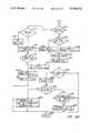
- FIG. 2is a schematic and block diagram of a programming system for use with the implantable stimulator of FIG. 1;
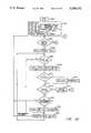
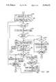
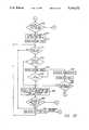
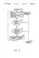
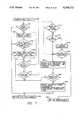
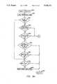
- FIGS. 3A, 3B, 3C, 3D, 4, 5, 6, 7, 8A and 8Bare flowchart illustrations of operating sequences of the implant of FIG. 1;
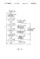
- FIGS. 9, 10A and 10Bare flowchart illustrations of operating sequences of the programming system of FIG. 2.
- the letter Igenerally represents electronic componentry installed in the implantable portion of a stimulator according to the present invention.
- the external portion or programming system(FIG. 2) is generally referred to as the letter P and is used to communicate with the implant I.
- the main component of the implant Iis a processor 20, preferably a CMOS microcomputer such as the 68C05 available from Motorola Semiconductor Products, Inc.
- the CMOS versionis preferable because this reduces the power consumed by the implant I.
- the processor 20includes a series of parallel input and output lines, an asynchronuous serial port and a timer which can generate interrupts.
- a resistor 26is connected between the voltage output of the regulator 24 and the voltage set input, with a resistor 28 connected between the voltage set input and ground. This is the basic feedback circuit utilized by the regulator 24 to regulate its output voltage.
- a control resistor 30is connected between the voltage set input of the regulator 24 and a digital output of the processor 20 to allow the processor 20 to control its own supply voltage V up . In this manner the supply voltage V up can be reduced from 2.8 volts to 1.4 volts during certain operating portions as will be explained to slow down operation of the processor 20 and thereby reduce power consumption. The voltage V up is increased during other operations of the processor 20 when higher speed operation is appropriate.
- a crystal 32, capacitor 34 and resistors 36 and 38are connected to the processor 20 according to instructions from the manufacture to produce the clocking signal for the processor 20. In the preferred embodiment the operating frequency is 76.8 kHz, but other values can be utilized if desired.
- An up converter 39 based on a CMOS step up switching regulator 40such as an MAX630 manufactured by Maxim Integrated Product, is used to develop the voltages necessary to drive the electrodes (not shown) connected to the vagus nerve according to U.S. Pat. No. 4,702,254 and to drive the transmitter portions of the implant I.
- the switching regulator 40is connected to the battery voltage V B by means of a transmit/converter coil 42.
- This transmit/converter coil 42serves the dual purpose of performing the inductance function in the up converter 39 and serving as the transmitter antenna for the radio frequency transmission portions of the implant I.
- the transmit/converter coil 42is connected between the battery voltage V B and the inductance input of the regulator 40.
- the anode of a diode 44is connected to the inductance input of the regulator 40, while the cathode of the diode 44 is connected to the supply voltage input of the regulator 40 and to one side of a capacitor 46. The other side of the capacitor 46 is connected to ground.
- a resistor 48is connected between the supply voltage input of the regulator 40 and the feedback or voltage sense input.
- a resistor 50has one terminal connected to the feedback voltage input of the regulator 40 and has its other terminal connected to the serial output of the processor 20.
- the resistor 50is used to set the feedback voltage to the regulator 40 at either high or low levels as necessary to cause the regulator 40 to produce a large signal during a low phase so that a large RF field is emitted from the coil 42 and no signal during a high phase so no RF field is emitted from the coil 42. This emitted RF field is then the transmitted signal from the implant I during communication or marker phases.
- three resistors 52, 54 and 56have one terminal connected to the voltage feedback input of the regulator 40 and their other terminals coupled to three outputs of the processor 20. These three resistors 52, 54 and 56 form a resistor divider network used to program the output voltage of the regulator 40.
- the regulator 40is designed such that the inductance output is pulsed whenever the voltage at the feedback terminal is less than 1.31 volts.
- a capacitor 58 used to set the oscillator frequency of the regulator 40is connected between ground and the capacitor input on the regulator 40.
- the oscillation frequencyis 40 kHz.
- Two resistors 60 and 62are connected in series between the battery voltage V B and ground to form a voltage divider pair.
- a capacitor 64is connected in parallel with the resistor 62, which is connected to ground.
- the connection point between the two resistors 60 and 62is connected to a battery level sense input of the regulator 40, which provides a low signal on a low battery output if the voltage at the low battery input is below 1.31 volts.
- the low battery output signalis provided to an input of the processor 20, this signal being pulled up to the microprocessor voltage V up by a resistor 66.
- the processor 20can determine when the battery voltage is low and set an appropriate flag for communication to the programmer P.
- An output from the processor 20is connected to an enable input of the regulator 40, to allow the processor 20 to disable operation of the regulator 40 when desired to reduce power consumption of the circuitry in the implant I.
- the up converter 39can be powered down when no radio frequency transmissions are occurring and when no drive is being supplied to the electrode.
- a programmable current source Cprovides the constant current which is supplied to the electrodes coupled to the vagus nerve.
- the currentis provided by an NPN transistor 70, whose emitter is connected to a resistor 72 whose other terminal is connected to a normally closed terminal 73 of a reed switch 74.
- the contact of the reed switch 74is connected to ground.
- the reed switch 74is used for manually initiating a treatment cycle, for disabling the drive to the electrodes and resetting the processor 20.
- the base of the transistor 70is connected to the output of an operational amplifier 76 and to one terminal of a resistor 78 whose other terminal is connected to ground.
- the emitter of the transistor 70is also connected to the parallel combination of a resistor 80 and a capacitor 82, which form the feedback components for the current source C.
- the second terminals of the capacitor 82 and the resistor 80are connected to the inverting input of the amplifier 76.
- Also connected to the inverting input of the amplifier 76are six resistors 84, 86, 88, 90, 92 and 94 which effectively form a binary ladder between six outputs of the microprocessor 20 and the inverting input of the amplifier 76.
- the six resistors 84-94perform the digital to analog conversion used in making the current source C programmable.
- the non-inverting input of the amplifier 76is connected to one terminal of a resistor 96 whose other terminal is connected to ground.
- the resistor 96is a selected value to allow precise trimming of the accuracy of the current source C.
- a resistor 100Also connected to the non-inverting input of the amplifier 76 is a resistor 100 whose other terminal is connected to the cathode of a precision voltage reference drawn for illustration purposes as a Zener diode 102 whose anode is connected to ground.
- a resistor 104which has its other terminal connected to an output of the processor 20. In this way the processor 20 can define a reference drive voltage to be used by the current source amplifier 76.
- a zero level voltage applied to the resistor 104shuts off the current source C.
- a resistor 106is connected between the cathode of the Zener diode 102 and the inverting input of the amplifier 76 to allow the lowest desired current setting, 0.25 mA, in the preferred embodiment, to be developed.
- a desired output for the current source Cis established by setting a non-zero level on the inverting input of the amplifier 76 by driving the output connected to the resistor 104 high and then driving the six digital to analog resistors 84-94 as desired to set the proper level.
- Power to the amplifier 76is provided by an output of the processor 20, allowing the amplifier 76 to be completely shut off during low power consumption periods.
- the drive or stepped up voltage as developed at the cathode of the diode 44, the output of the up converter 39,is provided to a resistor 110 whose other terminal is connected to the implant container.
- a capacitor 114is connected between the container and a capacitor 116, whose other terminal is connected to the negative electrode.
- the cathode of a Zener diode 118is also connected to capacitor 114, whose anode is connected to ground to limit the voltage that can be applied on the negative electrode.
- the anode of a diode 120is connected to the cathode of the Zener diode 118 and has its anode connected to the collector of the transistor 70.
- An NPN transistor 122has its emitter connected to the cathode of the Zener diode 118, its base connected to the cathode of the diode 120 and its collector connected to the positive electrode.
- a Zener diode 124has its cathode connected to the positive electrode and its anode connected to ground to provide overvoltage protection.
- a resistor 126is connected between the drive voltage and the base of the transistor 122 to bias the transistor 122 for operation.
- a capacitor 128is connected in parallel with the resistor 126.
- the sufficiency of the voltage present at the collector of the transistor 70, which is used to drive the positive electrode,is fed back to the processor 20 for use in determining the proper output voltage of the regulator 40. This is done by having a resistor 132 connected between the collector of the transistor 70 and the base of a PNP transistor 134. The emitter of the transistor 134 is connected to the microprocessor voltage V up , while the collector is connected to an input to the processor 20 and the parallel combination of a resistor 136 and a capacitor 138, whose other terminals are connected to ground.
- the processor 20can sense this point and raise the voltage output of the up converter 39 by appropriately decreasing the effective resistance supplied by the resistors 52, 54 and 56. This increases the available drive voltage so that the programmable current source C is properly driving the desired currents and is not in saturation or limiting.
- a normally open contact 71 of the reed switch 24is connected to an input of the processor 20 and is pulled up to the microprocessor voltage V up by a resistor 142. Also connected to this input of the processor 20 are the base and emitter of an NPN transistor 144. The collector of the transistor 144 is connected to the low true reset input of the processor 20 and to a capacitor which is connected to the microprocessor voltage V up . Voltage is supplied to the collector of the transistor 144 by means of a resistor 148 connected between the collector of the transistor 144 and the collector of a transistor 150. The transistor 150 is the drive transistor connected to the serial input of the processor 20 which is used to receive an incoming radio frequency transmission.
- the collector of the transistor 150is pulled up to the microprocessor voltage V up by a resistor 152.
- the emitter of the transistor 150is connected to ground.
- the base of the transistor 150is connected to two bias resistor 154 and 156, the resistor 154 being connected to ground, and the resistor 156 being connected to the battery voltage V B .
- Also connected between the base of the transistor 150 and groundis a Zener diode 158, which is used to protect the transistor 150 from any received high level input voltages.
- a capacitor 160is connected between the base of the transistor 150 and one terminal of a receive coil 162. The other terminal of the receive coil 162 is connected to ground.
- the receive coil 162receives a burst of radio frequency energy from the programmer P which is then filtered by the capacitor 160 and provided to the transistor 150 as the received input. While in the embodiment shown two separate inductors 42 and 162 are used for the functions of transmission, voltage development and reception, one single coil can be used to serve all three purposes to further save on space in the implant I.
- the sensitivity of the receive coil 162 and the biasing of the transistor 150are such that when the up converter 34 is operating the radio frequency field emitted by the transmitting/converting coil 42 interferes with reception by the transistor 150. However, when the up converter 39 is disabled the receive circuitry works properly to receive the transmissions from the programmer P.
- the transistor 150If the transistor 150 is turned on for a sufficient period of time, due to the presence of an received signal, and the reed switch 74 is activated, the capacitor 146 is charged to have a potential of the microprocessor voltage V up .
- transistor 150When the radio frequency signal is removed and the resistor 148 is connected to the microprocessor voltage V up through the resistor 152, transistor 150 is deactivated, a low level will momentarily appear on the reset input of the processor 20 until the capacitor 146 discharges through the resistors 148 and 152, thus allowing the processor 20 to be reset only by the combination of having the reed switch 74 activated and a sufficiently long burst of radio frequency energy received.
- the reset inputis kept at a high level because the transistor 144 does not allow the reset input to go to a low level. If the transistor 150 receives a signal, the voltage difference appears across the resistor 148 and the capacitor 146 remains generally discharged. If the magnet is removed before the radio frequency signal is removed, then the capacitor 146 is discharged through the base to collector diode of the transistor 144, resulting in resetting of the processor 20 if the radio frequency signal had been provided for a sufficient time. Thus the reset procedure is place the magnet to activate the reed switch 74, activate the programmer P to broadcast a stream of radio frequency energy for a sufficient time and stop the broadcast. Alternately, the magnet can be removed after a sufficient period of broadcasting.
- the radio frequency signals transmitted by the implant Iare received by a programmer P (FIG. 2), which also generates the signals received by the implant I.
- a programmed computersuch as a personal computer 200, which has a serial interface, has its serial output line 202 connected to a resistor 206 whose other terminal is connected to the anode of a diode 208.
- the cathode of the diode 208is connected to the cathode of a second diode 210 whose anode is connected to ground to provide reverse voltage protection.
- Also connected to the cathode of the diode 208is a resistor 212 whose other terminal is connected to the base of an NPN transistor 214.
- a resistor 216Connected between the base and emitter of the transistor 214 is a resistor 216, with the emitter being connected to ground.
- the collector of the transistor 214is pulled to a high voltage level by a resistor 216 and is connected to a resistor 218 who has its other terminal connected to the gate of a n-channel enhancement MOSFET transistor 220.
- the transistor 214thus serves as a level shifter and inverter between the serial output signals and the MOSFET 220.
- the source of the MOSFET 220is connected to ground while the drain is connected to a resistor 216 which is connected to the logic high level voltage.
- the voltage appearing at the drain of the MOSFET 220has the same logic state as the signal developed by the computer 200.
- the signal developed at the drain of the MOSFET 220is connected to the reset inputs of a dual multivibrator 224.
- the first multivibrator 224a in the dual unit 224is connected for astable operation, preferably with a frequency of approximately 100 kHz to provide the basic signal which is coupled to the transceiving coils 226 and 228.
- the output of the first multivibrator 224ais coupled to a push/pull transistor amplifier 230 whose output is connected to the gate of an n-channel enhancement MOSFET transistor 232 whose source is connected to ground and whose drain is connected to one terminal of the parallel combination of the coil 226 and a capacitor 234.
- the other terminal of the parallel combination of the coil 226 and a capacitor 234is connected to the battery voltage as supplied by batteries 310 and 312 which power the programmer P.
- a capacitor 236is connected between the battery voltage and ground.
- the output of the first multivibrator 224ais connected to the trigger input of the second multivibrator 224b of the multivibrator 224 so that the second multivibrator 224b inverts the output of the first multivibrator 224a.
- These operationscan be performed by the multivibrators located on the ICM7556 manufactured by Intersil, Inc.
- the output of the second multivibrator 224bis connected to a similar push/pull transistor amplifier 238 whose output is similarly connected to the gate of an n-channel enhancement MOSFET 240.
- the source of the transistor 240is connected to ground while the drain is connected to the parallel combination of the coil 228 and a capacitor 242 whose other terminals are connected to the battery voltage.
- the two coils 226 and 228are preferably located to form an X or cross so that the signal that they produce is in two different planes to increase likelihood of proper reception by the implant I and receipt by the coils 226 and 228 of any signals produced by the
- the drain of the MOSFET 232is connected to a capacitively coupled amplifier circuit 244 whose output is connected to the inverting input of a comparator 246.
- the amplifier circuit 244filters out the 40 kHz carrier frequency of the signal produced by the implant I so that the transmitted serial data is recovered.
- the drain of the MOSFET 240is connected to a similar capacitively coupled amplifier circuit 248 whose output is connected to the inverting input of a comparator 250.
- the non-inverting inputs of the comparators 246 and 250are connected to the junction between resistor 252 and potentiometer 254 whose other terminals are respectively connected to high level voltage and ground.
- the wiper arm of the potentiometer 254is connected to two resistors 256 and 258 which are connected, respectively, to the inverting inputs of the comparators 246 and 250.
- the signalis amplified by the appropriate amplifier 244 or 248 and applied to the comparator 246 or 250 so that a low level signal develops at the output of the appropriate comparator 246 or 250.
- the outputs of the two comparators 246 and 250are connected together and pulled up to a logic high level by a resistor 260.
- the output of the comparators 246 and 250is also applied to a resistor 262, whose other terminal is connected to the base of a PNP transistor 264 and to one terminal of a capacitor 266.
- the second terminal of the capacitor 266is tied to a high level voltage for noise filtering.
- the signal which is applied to the base of the transistor 264is essentially an inverted form of the signal supplied by the serial output of the processor 20, which is applied to the resistor 50 to control the voltage level output of the regulator 40.
- the emitter of the transistor 264is connected to the junction point of two resistors 268 and 270 whose other terminals are connected to, respectively, voltage high level and ground.
- the collector of the transistor 264is connected to the non-inverting input of an operational amplifier 272 and to a resistor 274 whose other terminal is connected to ground.
- the inverting input of the comparator 272is connected to the junction point between a resistor divider pair formed by resistors 276 and 278, whose other terminals are respectively connected to ground and a high level voltage to set a reference level.
- the output of the amplifier 272is provided through a resistor 280 to the serial input of the computer 200 and through a resistor 284 to the anode of a light emitting diode (LED) 286 whose cathode is connected to ground.
- LEDlight emitting diode
- the LED 286is used to indicate when a signal is being received from the implant I, which signal is supplied to the computer 200.
- the computer 200can communicate with the implant I via its conventional serial link.
- the output of the operational amplifier 272is provided to a level shifting inverter 288, which provides a signal to diagnostic equipment 290.
- the diagnostic equipment 290can thus receive marker pulses which are produced by the implant I under certain conditions.
- the marker pulsesare provided to allow the diagnostic equipment 290 to synchronize with the implant I to allow easier analysis and diagnosis of the implant's operation and the patient's condition.
- the cathode of a diode 300is connected to the collector of the transistor 214.
- the anode of the diode 300is connected to one terminal of a capacitor 302, one terminal of a resistor 304 and the gate of a P channel enhancement MOSFET 306.
- the second terminals of the capacitor 302 and resistor 304are connected to a high voltage level, as is the source of the MOSFET 306.
- the drain of the MOSFET 306is connected to the base of the transistor 264, so that whenever the multivibrator 224 is activated, causing a radio frequency signal to be transmitted to the implant I, the transistor 264 is clamped to a high level voltage so that no signal is provided to the amplifier 272 and thus back to the computer 200.
- Poweris supplied to the programmer P by two batteries 310 and 312, which are connected in series with each other and in parallel with a diode 314.
- the diodeis connected with the cathode connected to the positive voltage and the anode connected to ground.
- the positive battery voltage BATis applied to a capacitor 316, a resistor 318 and the source of a P channel enhancement MOSFET 320.
- the gate of the MOSFET 320 and the second terminals of the capacitor 316 and the resistor 318are connected to one terminal of a resistor 322, whose other terminal is connected to ground and to the collector of an NPN transistor 324.
- connection to groundis used only when the programmer P is connected to the computer 200, thereby enabling the MOSFET 320 to provide voltage to a voltage regulator 336 which provides the power for the remaining components in the programmer P when the programmer P is connected to the computer 200.
- the emitter of the transistor 324is connected to ground, while the base is connected to a resistor 326, whose other terminal is connected to ground, and to a resistor 328.
- the second terminal of the resistor 328is connected to one terminal of a resistor 330, whose other terminal is connected to one terminal of a reset switch 332.
- the other terminal of the reset switch 332is connected to the battery voltage BAT.
- the signal present at the junction of the resistors 328 and 330is provided to the cathode of the diode 208.
- the reset switch 332can then be used to provide a signal to the transistor 324, activating the series MOSFET 320 and simultaneously activating the multivibrator 224 to begin a continuous transmission. If the reset switch 332 is held for a sufficient period, 20-25 seconds in the preferred embodiment, the implant I resets, assuming the magnet is in location as described above. Thus the implant I can be reset when the programmer P is not available.
- the drain of the series MOSFET 320is connected to a capacitor 334 connected to ground and to the input terminal of a three terminal voltage regulator 336.
- the reference leg of the three terminal regulator 336is tied between two resistors 338 and 340, with the resistor 338 being connected to ground and the resistor 340 being connected to the output of the regulator 336.
- the output of the regulator 336is the high logic level voltage used in the programmer P and has a capacitor 342 connected to ground for filtering purposes.
- the input voltage to the three terminal regulator 336is also provided to a low battery indication circuit 344 which has an LED 346 to provide a low battery indication.
- the programmer Pcan be used with the computer 200 to provide commands to or receive messages from the implant I or can be used uncoupled from the computer 200 to reset the implant I when used in conjunction with the magnet used to control the reed switch 74.
- the operating sequence of the implant Icommences at the start sequence 500 (FIG. 3A).
- the processor 20clears the memory; initializes all programmable values, such as the parameters utilized with the serial port contained in the processor 20; initializes the total treatment time to zero hours; initializes the total operating time at 1 hour; initializes the treatment time per day at 24 hours; initializes default normal and magnet mode stimulation pulse amplitudes and frequencies; sets the stimulation interval at 60 minutes and sets a zero hour delay.
- the processor 20also increases the voltage supplied by the regulator 24 and programs the up converter 39 and the current source C.
- the processor 20sets up the internal timer and enables its interrupt. The timer is preferably set to overflow every 6.826 seconds.
- controlproceeds to step 508 where the total operating time is updated to indicate the passage of the 6.826 second interval and the delay counter is decremented.
- Controlthen proceeds to step 510 to determine if a space character with proper parity has been received over the communication interface during a 300 msec window. This is done by shutting off the up converter 39 for approximately 300 msec and monitoring the serial port. Thus the noise generated by the up converter 39 is removed periodically, allowing the receive circuitry to be greatly simplified. If a space character with proper parity has been received, this is an indication that the programmer P is attempting to communicate with the implant I and therefore control proceeds to step 512, the receive parameters sequence 600 (FIG. 4).
- step 514After the parameters have been received in step 512 or if a space was not received during the listening interval, control proceeds to step 514 to check to see if the delay period is over. If not, control proceeds to step 516 to determine if programming occurred in step 512. If so, control returns to step 504 to reinitiate the loop. If no programming occurred, control proceeds to step 518 where the various parameters, such as pulse amplitude, pulse frequency, pulse width, magnet activation pulse width, stimulation burst time, simulation burst interval, treatment time of day, magnet activation amplitude, and magnet activation stimulation burst time, are checked to see if the parameters are valid. If not, valid parameters are loaded. Control then proceeds to step 520 where the monitor reed switch sequence 700 (FIG.
- step 7is called to determine if manual activation is desired. There are two exits from the monitor reed switch routine 700, with the first occurring if programming occurred, in which case control proceeds to step 504. If programming of the parameters did not occur during the monitor reed switch routine 700, control proceeds from step 520 to step 506.
- step 515control proceeds to step 515, where the implant I is placed in run mode.
- the microprocessor voltage V upis increased to the high level, the up convertor 39 is enabled and power is supplied to the amplifier 74.
- Controlthen proceeds to step 522 where an internal value referred to as the stimulation counter is set to stimulation on time.
- step 524a flag is set indicating that stimulation is on and a stimulation off flag is cleared.
- step 526determines if 6.826 seconds have elapsed and it is time to monitor for a communications attempt. If not, control proceeds to step 528 which is a reference to the monitor reed switch sequence 700. If programming occurs during this operation of the monitor reed switch sequence 700, control proceeds from step 528 to step 504. If no programming occurred, control proceeds to step 530 to determine if magnet stimulation occurred. If not, control proceeds to step 526. If magnet stimulation did occur, control proceeds to step 532 (FIG. 3C).
- step 534determines if the implant I is in the process of ramping the pulse amplitude. If so, control proceeds to step 538. If ramping is not in effect, control proceeds from step 536 to step 540 to determine if a space character has been received using the process described in step 510. If not, control proceeds to step 538. If a space has been received control proceeds to the receive parameter sequence 600 in step 542. After completing the receive parameter sequence 600, step 542 transfers control to step 543 where the implant I is placed in run mode. Control then proceeds to step 544 to determine if programming occurred during the receive parameter sequence 600. If so, control returns to step 504. If not, control proceeds to step 538.
- step 538the processor 20 determines whether the parameters as indicated above are valid and updates the total operating time to indicate the 6.826 second elapsed time. Control proceeds to step 546 where the total treatment time for the day is monitored. If the total treatment time for the day has been exceeded, then control proceeds to step 548 (FIG. 3D). If the treatment time has not been exceeded, control proceeds to step 550 which decrements the stimulation counter to reduce the remaining stimulation time. Control then proceeds to step 552 to determine if the stimulation counter is zero. If the counter is not zero, indicating that the stimulation period has not ended, control proceeds to step 528. If the stimulation counter is equal to zero, this indicates an end to the stimulation period and control proceeds to step 554. In step 554 the stimulation on flag is cleared.
- Controlproceeds to step 551 where the processor 20 determines if the stimulation pulse frequency is greater than 5 Hz. If so, control proceeds to step 553 to cause the pulse to ramp down. Control proceeds to step 555, which is also where control proceeds if the stimulator pulse frequency is not greater than 5 Hz. In step 555 the stimulation off flag is set. Control then proceeds to step 532.
- step 532the stimulation counter value is set to that of the stimulation off time and control proceeds to step 556.
- step 556a determination is made as to whether a 6.826 second period has elapsed. If so, control proceeds to step 558 to determine if the pulse amplitude is ramping down. If not, control proceeds to step 559 where standby mode is entered.
- step 560determines if a space character is received over the communication interface during the listening period. If so, control proceeds to step 562, which calls the receive parameter sequence 600 to proceed with the communication sequence. After completing the communication sequence, control proceeds from step 562 to step 563 where run mode is activated. Control proceeds to step 564 where a determination is made as to whether programming did occur in the receive parameter sequence 600. If so, control proceeds to step 504. If not, control proceeds to step 566 which is also where control proceeds if the space character has not been received in step 560 or if the pulse amplitude was ramping as determined in step 558.
- step 566the processor 20 checks for valid parameters and updates the total operating time. Control then proceeds to step 568 where the total treatment time per day is monitored and adjusted. If the total treatment time per day has been exceeded, control proceeds to step 548. If the time has not been exceeded, control proceeds to step 570 where the stimulation counter is decremented to count down the off time. In step 571, which follows step 570, the processor 20 determines if the stimulation counter equals zero. If so, control proceeds to step 504. If the off time has not been completed, control proceeds to step 572 which calls the monitor reed switch sequence 700. If programming occurred during the operation of the monitor reed switch sequence 700, control proceeds to step 504. If no programming occurred, control proceeds to step 556 to loop during the off interval. Thus, under general operating conditions the processor 20 will loop between the stimulation off and stimulation on time sequences.
- step 548(FIG. 3D) where a determination is made as to whether the treatment time per day is 24 hours per day. If so, control returns to step 504. If treatment is not enabled all 24 hours of a day control proceeds to step 574, where the treatment time per day delay is loaded into a counter. Control proceeds to step 575 where the processor 20 places the implant I in standby mode. Control proceeds to step 576 to determine if a 6.826 second period has elapsed. If so, control proceeds to step 578 to determine if the pulse amplitude is in a ramp mode. If not, control proceeds to step 579 where the implant I is placed in standby mode.
- Controlproceeds to step 580 to determine if a space character is received during the listening period. If so, control proceeds to step 582 which calls the receive parameter sequence 600 to perform any communications. Control proceeds from step 582 to step 583 where the implant I is placed in run mode. Control proceeds to step 584 to determine if programming had occurred. If so, control returns to step 504. If not, control proceeds to step 586, which is also where control proceeds from step 580 if a space character was not received or from step 578 if the amplitude was ramping.
- step 586a check is made to determine if the parameters are still valid, the total operating time is updated and the treatment time per day delay is decremented. Control then proceeds to step 588 to determine if the treatment time per day delay is over. If so, control proceeds to step 504 and treatment commences. If not, control proceeds to step 590, which is also where control proceeds if the 6.826 second period has not elapsed in step 576.
- step 590the monitor reed switch sequence 700 is called. If programming occurs during the monitor reed switch sequence 700, control proceeds to step 504. If no programming occurred, control proceeds from step 590 to step 576 to complete the delay period until the next treatment time.
- the receive parameters sequence 600commences in step 602 by having the processor 20 echo back a space character. This is accomplished by loading a space character with proper parity into the serial out register in the processor 20, which shifts out the bits, changing the up convertor 39 output voltage based on the state of the bit as the particular character is being shifted out. In this manner the up convertor 39 applies energy to the coil 42 in a patterned manner so that, given a basic operating frequency of 40 kHz in the preferred embodiment, a series of large amplitude 40 kHz pulses is transmitted when the up convertor 39 is set for a high voltage as in a zero bit and no pulses are transmitted when a one bit is being transmitted by the serial port.
- the output of the coil 42is a series of 40 kHz signals bursts and no signal, depending on the bit value being shifted out of the serial port.
- All characters received or transmittedinclude parity bits which are used to improve error detection. Any transmission of a character includes the parity bit and any evaluation of a received character includes a parity check. If the parity check fails, the character is not considered to be received.
- step 604determines if this input character, which is indicated as the SCDAT value, is equal to the letter P to indicate a desire to enter programming mode. If not, control proceeds to step 606 to determine if the received character value was equal to an I to indicate a desire to enter the interrogate mode. If not, control proceeds to step 608, which disables the transmit portions of the serial port and control proceeds to step 610 which is a return from the sequence. If in step 606 the character was determined to be an I character, control proceeds to step 612 where the I character is echoed back and an additional A character is transmitted to indicate the particular model of the implant I.
- step 612control proceeds to step 614 where the interrogate sequence 670, (FIG. 6) is called. Control proceeds from step 614 to step 608.
- step 604determines whether a P character has been received. If it is determined in step 604 that a P character has been received, control proceeds to step 616, where the P character is echoed back and an A character is transmitted to indicate the particular model. Control proceeds to step 618 to receive the next character transmitted by the programmer P. If in step 620, the next step, the processor 20 determines that the received character is not an A character control proceeds to step 608. In this way programming, which may have effects on the operation of the implant I, utilizes a triple handshake, while an interrogation which merely receives values uses only a double handshake. If the A character is determined as having been received in step 620, control proceeds to step 622 which calls the program sequence 650 (FIG. 5) to allow programming of the implant I. Control proceeds from step 622 to step 608.
- the program sequence 650commences in step 652. If at any time during the operations of step 652 two seconds elapses with no communication from the programmer P, control proceeds to step 654, which is a return from the program sequence 650.
- the processor 20reads in the desired parameter address as transmitted by the programmer P and echoes this value back to the programmer P. After the address operations are completed, the processor 20 reads in and echoes back the selected parameter value and then reads in and echoes back a checksum value. By utilizing the echo back procedure for each value the programmer P can determine if the programming process is proceeding correctly and if not, can abort operations simply by not transmitting for two seconds. If the echoed back values are correct, the programmer P proceeds with the next value to be transmitted.
- controlproceeds to step 656 where the address value and the parameter value are summed and compared against the checksum value. If they are not equal, control proceeds to step 654 to abort the programming. If the values are equal, control proceeds to step 658 to determine if the address is a valid address and if the parameter values are within valid ranges. If not, control proceeds to step 654. If so, control proceeds to step 660 where the parameter value is stored at the address desired. Control then returns to step 652 to await a time out or additional programming if desired.
- the interrogate routine 670commences at step 672.
- the processor 20transmits a double quote symbol to indicate the beginning of the interrogation transmission.
- an index valueis set to zero so that all of the 64 parameter values can be readily transmitted.
- the processor 20then proceeds to step 673 to determine the address value of the first parameter by using a parameter starting address for particular serial number of the model implant I, which is added to the index value. This address value is then transmitted from the implant I to the programmer P. The parameter value located at the address value is then loaded and transmitted. Following this the checksum is determined by adding the address and parameter values. The checksum is then transmitted to the programmer P. Following the checksum transmission, the index value is incremented by one.
- the monitor reed switch sequence 700commences at step 702, where the processor 20 determines whether the reed switch 74 is closed by the magnet by interrogating the input port. If not, control proceeds to step 704 which is a return from the sequence which indicates that programming was not accomplished. If the reed switch 74 is closed, control proceeds to step 704 where the processor 20 waits until the reed switch 74 is opened, that is, the magnet removed. Control then proceeds to step 706 where the closure time of the reed switch 74 is evaluated to determine if it was closed more than one minute. If so, this is an erroneous condition and control proceeds to step 704.
- step 708a magnet stimulation flag is set and the stimulation counter is set to the magnet stimulation on time. This is the time in which stimulation is provided based on a manual demand. This feature allows the user or treating physician to trigger stimulation at any desired time.
- the use of programmed and manually triggered stimulation times and pulse parameterspermits different treatment modalities if desired.
- Controlproceeds from step 708 to step 710, where processor 20 determines if the reed switch 74 is closed, after a given interval to allow the reed switch 74 to finish bouncing. If the reed switch 74 is still closed, then control returns to step 704. If the reed switch 74 is not closed after the debounce time, control proceeds to step 712 to determine if 6.826 seconds have elapsed. If not, control returns to step 710. If the time period has elapsed, control proceeds to step 714 to determine if the applied signal is in ramping mode. If not, control proceeds to step 716 to determine if a space character is received during a listening period. If so, control proceeds to step 718 where the receive parameter sequence 600 is called.
- step 720Control then proceeds to step 720 after returning from the receive parameter sequence 600 called in step 718.
- the processor 20determines whether programming occurred. If programming had occurred, control proceeds to step 722 which is a return from the monitor reed switch sequence 700 which indicates that programming had occurred. If programming had not occurred in step 720, control proceeds to step 724, which is also where control proceeds from step 716 if a space has not been received or from step 714 if the pulse was in ramping mode.
- step 724the total operating time is updated by incrementing its value, the total treatment time is updated by incrementing to the proper value and the stimulation counter is decremented to indicate the reduction of the remaining period of stimulation.
- Controlthen proceeds to step 726 to determine if the stimulation counter has reached a zero value. If not, control returns to step 710. If the counter value has reached zero, then the manually activated stimulation period has completed and control proceeds to step 728, where the magnet activation diagnostics are updated to indicate an additional magnet activation and the total operating time at which the magnet was activated. These values can be used for various purposes by the physician. Also in step 728 the pulse amplitude is ramped down if necessary and the magnet stimulation flag is cleared to indicate that magnet stimulation is not occurring. Control then proceeds to step 704 for a not programmed return to the calling sequence.
- the timer interrupt 800(FIG. 8A) is an interrupt routine which operates transparent to or in the background of all of the proceeding sequences.
- the timer interrupt routineoperates whenever the internal timer value has counted to equal the value in a compare register which is loaded by the processor 20. During stimulation this value is set so that the interrupts occur at the stimulation frequency.
- the timer interrupt routine 800starts at step 802 where the timer is loaded with the frequency value or time to develop the pulse spacing of the applied pulse. In this manner the timer is actually utilized to control the pulse width of the applied treatment pulses. Control proceeds to step 804 to determine if the ramp down process is occurring. If not, control proceeds to step 806 to determine if the magnet stimulation flag is set.
- step 808determines if the stimulation on flag is set. If the answer was yes in either of steps 806 or 808, control proceeds to step 810 (FIG. 8B) to determine if a ramp up is finished. If the ramp up is not finished, control proceeds to step 811 where a determination is made if the stimulation frequency is 5 Hz or less, which indicates the implant I is in marker mode. If so, control proceeds to step 813 where the output current is set to the desired maximum. Control proceeds to step 814. If not in marker mode, control proceeds to step 812 which increases the pulse output current amplitude by one counter value of the D/A convertor as developed by the resistors 84-94. Control then proceeds to step 814 to determine if the magnet stimulation flag is set.
- controlproceeds to step 816 and the pulse width of the particular output is set to be that of the normal pulse width. If the stimulation flag is set as determined in step 814, control proceeds to step 818 where the pulse width is set to the magnet pulse width as set in the parameters. After step 816 or step 818 control proceeds to step 820, where the treatment pulse is transmitted.
- the pulseis developed by enabling the appropriate resistors 84-94 to ground, not enabling the other resistors 84-94, providing the voltage reference to the amplifier 74 and activating the up converter 39.
- the pulse timeis developed in a software timing loop. Control proceeds to step 822, which is a return from the timer interrupt routine 800 to the interrupted instruction.
- step 810determines if a ramp up is finished. If at step 810 it is determined that a ramp up is finished, control proceeds to step 824 to determine if the magnet stimulation flag is set. If not, control proceeds to step 826 where the pulse width is set to be the normal pulse width. If the magnet stimulation flag is set in step 824, control proceeds to step 828 where the pulse width for the pulse to be developed is set to the magnet pulse width value. Control proceeds from either step 826 or step 828 to step 830, where the treatment pulse is transmitted. Control proceeds to step 832 where a counter used to determine if it is time to try and reduce the value being applied to the up convertor 39 is decremented. It is desireable to set the up convertor voltage at the lowest possible voltage and yet have sufficient margin to insure the desired current is actually being supplied to the patient.
- Controlproceeds to step 834 to determine if the up convertor count value is equal to zero. If the up convertor count is not equal to zero, this is an indication that it is not appropriate at this point to check the output amplitude value. Control then proceeds to step 822 for a return to the interrupted sequence. If the up convertor count is equal to zero, then control proceeds to step 836 where the count value is reinitiated to ten, so that every ten cycles through the timer interrupt routine 800 the voltage value may be evaluated. Control then proceeds to step 838, where the voltage level of the collector of the transistor 134 is evaluated to determine if the output voltage amplitude is acceptable.
- step 838If the amplitude is not acceptable, control proceeds from step 838 to step 840 where the up convertor output amplitude is incremented to provide more voltage and a flag is set indicating that the up convertor output value should not be decremented. Control then proceeds to step 822 for a return from the timer interrupt routine 800.
- step 842the processor 20 determines if the up convertor amplitude can be decremented. If not, control proceeds to step 822. If the up convertor amplitude can be decremented, control proceeds to step 844 where the up convertor amplitude is actually decremented. In this manner the voltage supplied by the up convertor 39 is reduced if desireable to conserve energy and to limit the applied voltage. Control proceeds to step 822.
- step 808determines whether the stimulation on flag is not set. If in step 808 it is determined that the stimulation on flag is not set, control proceeds to step 846 to determine if the treatment time per day delay is active, that is, if stimulation should not occur for a given period. If so, control proceeds to step 848, which is a return to the interrupted sequence. If the treatment time per day delay is not active, control proceeds from step 846 to step 850 to determine if the stimulation off flag is set. If so, control proceeds to step 848. If not, control proceeds to step 852, which is also where control would proceed if it was determined in step 804 that the implant I was ramping down the applied signal. In step 852 the processor 20 determines whether the amplitude of the applied pulse is equal to zero. If it is, control proceeds to step 848. If it is not equal to zero, control proceeds to step 854 where the amplitude of the applied signal is decremented. Control then proceeds to step 848 for a return from the time interrupt routine 800.
- step 900The operating sequence for the computer system 200 begins at step 900 (FIG. 9) which is the start of the sequence.
- Controlproceeds to step 902 where the main menu is displayed with the available options. These options include interrogation of the implant I, programming of the implant I, setting of patient information, data base functions and exiting the program.
- step 904to determine if interrogation was required. If so, control proceeds to step 906 where interrogate mode is set.
- step 908which is the transmit routine 1000 (FIG. 10A) which handles the actual communication with the implant I. Control then returns to step 902 after the transmit routine 1000 is completed.
- step 904control proceeds from step 904 to step 910 to see if programming is desired. If so, control proceeds to step 912 where the desired parameters to be programmed into the implant I are obtained and programming mode is set. Control then proceeds to step 908.
- step 914If programming mode was not desired in step 910, control proceeds to step 914 to see if patient information was to be set. If so, control proceeds to step 916 to receive the necessary patient information, such as name, implant model and so on. Control then proceeds to step 902. If patient information was not requested, control proceeds from step 914 to step 916. If data base functions are desired, control proceeds from step 916 to step 920, where the particular data base operations are performed. Various statistics relating to the on-time usages and other parameters as stored by the implant I and accumulatively stored by the computer system 200 can be performed using data base capabilities. After the data base operations are complete, control proceeds from step 920 to step 902. If data base functions were not desired, control proceeds from step 916 to step 922. If exit or no options are desired, control proceeds to step 924 which exits the program and returns control to the operating system of the computer system 200. If exiting was not desired, control returns to step 902.
- the transmit routine 1000commences at step 1002 by transmitting a space character using the programmer P to the implant I.
- step 1004a check is made to see if this was the last try in transmitting a space character. If so, and successful communication has not been achieved with the implant I, control proceeds to step 1006, which is a return to the calling sequence.
- step 1008checks to see if a timeout has occurred. A particular time is allotted between retransmissions of the space character and if this time has elapsed, control returns to step 1002 to transmit another space character. If timeout has not occurred, control proceeds to step 1010 to see if a valid space has been received from the implant I. If not, control returns to step 1008. If so, control proceeds to step 1012 to determine if programming or interrogation mode is desired. If programming mode is desired, control proceeds to step 1014 where a P character is transmitted to the implant I to indicate programming mode. In step 1016 a check is made to see if a valid P character has been received back from the implant I as part of the handshake process.
- controlproceeds to step 1018 where an error message is generated and to step 1020 which is a return to the calling sequence. If the P character was validly received, control proceeds to step 1022 where the model number is received from the implant I, if appropriate. In step 1024 the determination is made as to whether this is the proper model number as indicated in the patient parameters. If not, an error message is displayed in step 1026 and control returns to the calling sequence in step 1028.
- step 1024control proceeds from step 1024 to step 1030 where the A character in the case of an A model unit is transmitted to the implant I to proceed in the handshake process.
- step 1032the address of the first parameter to be changed is transmitted to the implant.
- step 1034the processor 20 checks to see if the implant I has echoed this address back to the programmer P. If not, control proceeds to step 1036 where an error message is displayed and to step 1038 where control returns to the calling sequence. If the address was correctly echoed, control proceeds from step 1034 to step 1040 (FIG. 10B) where the actual parameter value is transmitted. Control then proceeds to step 1042 to determine if the value was echoed by the implant I.
- step 1044an error message is generated and to step 1046 which returns operation to the calling sequence. If the value was correctly echoed, control proceeds from step 1042 to step 1048 where the checksum is determined and transmitted to the implant I. In step 1050 a check is made to see whether the checksum was properly echoed. If not, control proceeds to step 1052 and an error message is generated and to step 1054 which returns control to the calling sequence. If the checksum was properly echoed, control proceeds to step 1056 to determine if any more parameters are to be transmitted. If so, control returns to step 1032 and the process repeats. If there are no more parameters to be transmitted, control proceeds to step 1058 which is a return to the calling sequence.
- step 1012determines if the I character was echoed by the implant. If not, control proceeds to step 1074 where an error message is generated and to step 1076 which returns control to the calling sequence. If the character was properly echoed, control proceeds from step 1072 to step 1078 where the model number is received. Control then proceeds to step 1080 where the first set of data is received from the implant I. Control proceeds to step 1082 to determine if this was the last data value set to be received. If so, control proceeds to step 1084 which is a return to the calling sequence.
- step 1086determines if the communication sequence has timed out. This will generally occur either in erroneous cases where the programmer P has been moved or where the implant I has ceased transmitting data, such as at the end after completion of all data. If timeout has not occurred, control proceeds from step 1086 to step 1080 to receive the next data set. If the timeout has occurred, control proceeds to step 1084 and thus to the calling sequence.
- the implant Iis operating at full power only during stimulation times and at other periods is operating at reduced power levels to conserve battery life. At all times, even during stimulation intervals, the implant I periodically reduces its radio frequency emissions and monitors a communication channel, increasing the reliability of the receiver circuitry. When the implant I is providing stimulation at below a given frequency marker pulses are developed to allow diagnostic equipment to monitor implant I operation. Additionally, by using parity and multiple handshaking of data being transmitted from the programmer P to the implant I data errors are reduced and simple communications circuitry can be used.
Landscapes
- Health & Medical Sciences (AREA)
- Engineering & Computer Science (AREA)
- Radiology & Medical Imaging (AREA)
- Veterinary Medicine (AREA)
- Public Health (AREA)
- General Health & Medical Sciences (AREA)
- Animal Behavior & Ethology (AREA)
- Neurosurgery (AREA)
- Life Sciences & Earth Sciences (AREA)
- Biomedical Technology (AREA)
- Nuclear Medicine, Radiotherapy & Molecular Imaging (AREA)
- Neurology (AREA)
- Physics & Mathematics (AREA)
- Automation & Control Theory (AREA)
- Radar, Positioning & Navigation (AREA)
- General Physics & Mathematics (AREA)
- Electromagnetism (AREA)
- Acoustics & Sound (AREA)
- Electrotherapy Devices (AREA)
Abstract
Description
Claims (6)
Priority Applications (4)
| Application Number | Priority Date | Filing Date | Title |
|---|---|---|---|
| US07/434,985US5154172A (en) | 1989-11-13 | 1989-11-13 | Constant current sources with programmable voltage source |
| US07/802,736US5235980A (en) | 1989-11-13 | 1991-12-05 | Implanted apparatus disabling switching regulator operation to allow radio frequency signal reception |
| US07/802,740US5179950A (en) | 1989-11-13 | 1991-12-05 | Implanted apparatus having micro processor controlled current and voltage sources with reduced voltage levels when not providing stimulation |
| US07/802,735US5186170A (en) | 1989-11-13 | 1991-12-05 | Simultaneous radio frequency and magnetic field microprocessor reset circuit |
Applications Claiming Priority (1)
| Application Number | Priority Date | Filing Date | Title |
|---|---|---|---|
| US07/434,985US5154172A (en) | 1989-11-13 | 1989-11-13 | Constant current sources with programmable voltage source |
Related Child Applications (3)
| Application Number | Title | Priority Date | Filing Date |
|---|---|---|---|
| US07/802,740DivisionUS5179950A (en) | 1989-11-13 | 1991-12-05 | Implanted apparatus having micro processor controlled current and voltage sources with reduced voltage levels when not providing stimulation |
| US07/802,735DivisionUS5186170A (en) | 1989-11-13 | 1991-12-05 | Simultaneous radio frequency and magnetic field microprocessor reset circuit |
| US07/802,736DivisionUS5235980A (en) | 1989-11-13 | 1991-12-05 | Implanted apparatus disabling switching regulator operation to allow radio frequency signal reception |
Publications (1)
| Publication Number | Publication Date |
|---|---|
| US5154172Atrue US5154172A (en) | 1992-10-13 |
Family
ID=23726521
Family Applications (1)
| Application Number | Title | Priority Date | Filing Date |
|---|---|---|---|
| US07/434,985CeasedUS5154172A (en) | 1989-11-13 | 1989-11-13 | Constant current sources with programmable voltage source |
Country Status (1)
| Country | Link |
|---|---|
| US (1) | US5154172A (en) |
Cited By (243)
| Publication number | Priority date | Publication date | Assignee | Title |
|---|---|---|---|---|
| US5391191A (en)* | 1990-04-24 | 1995-02-21 | Siemens Aktiengesellschaft | Device for tissue stimulation |
| US5441527A (en)* | 1992-02-20 | 1995-08-15 | Amei Technologies Inc. | Implantable bone growth stimulator and method of operation |
| USD361555S (en) | 1993-02-17 | 1995-08-22 | Amei Technologies Inc. | Combined programmer and monitor for an implantable tissue growth stimulator |
| US5524624A (en)* | 1994-05-05 | 1996-06-11 | Amei Technologies Inc. | Apparatus and method for stimulating tissue growth with ultrasound |
| US5565005A (en)* | 1992-02-20 | 1996-10-15 | Amei Technologies Inc. | Implantable growth tissue stimulator and method operation |
| WO1997013550A1 (en) | 1995-10-13 | 1997-04-17 | Jacob Zabara | Heart rhythm stabilization using a neurocybernetic prosthesis |
| US5690681A (en)* | 1996-03-29 | 1997-11-25 | Purdue Research Foundation | Method and apparatus using vagal stimulation for control of ventricular rate during atrial fibrillation |
| US5833709A (en)* | 1996-04-25 | 1998-11-10 | Medtronic, Inc. | Method of treating movement disorders by brain stimulation |
| US5978702A (en)* | 1996-05-13 | 1999-11-02 | Medtronic, Inc. | Techniques of treating epilepsy by brain stimulation and drug infusion |
| US6104956A (en)* | 1996-05-31 | 2000-08-15 | Board Of Trustees Of Southern Illinois University | Methods of treating traumatic brain injury by vagus nerve stimulation |
| EP0588957B1 (en)* | 1991-06-14 | 2000-09-20 | Cyberonics, Inc. | Voice suppression of vagal stimulation |
| US6125300A (en)* | 1998-09-11 | 2000-09-26 | Medtronic, Inc. | Implantable device with output circuitry for simultaneous stimulation at multiple sites |
| US6466822B1 (en) | 2000-04-05 | 2002-10-15 | Neuropace, Inc. | Multimodal neurostimulator and process of using it |
| US6473639B1 (en) | 2000-03-02 | 2002-10-29 | Neuropace, Inc. | Neurological event detection procedure using processed display channel based algorithms and devices incorporating these procedures |
| US6516227B1 (en) | 1999-07-27 | 2003-02-04 | Advanced Bionics Corporation | Rechargeable spinal cord stimulator system |
| US6529774B1 (en) | 2000-11-09 | 2003-03-04 | Neuropace, Inc. | Extradural leads, neurostimulator assemblies, and processes of using them for somatosensory and brain stimulation |
| US6591138B1 (en) | 2000-08-31 | 2003-07-08 | Neuropace, Inc. | Low frequency neurostimulator for the treatment of neurological disorders |
| US6622041B2 (en) | 2001-08-21 | 2003-09-16 | Cyberonics, Inc. | Treatment of congestive heart failure and autonomic cardiovascular drive disorders |
| WO2003076008A1 (en) | 2002-03-14 | 2003-09-18 | Brainsgate Ltd. | Technique for blood pressure regulation |
| US20030181958A1 (en)* | 2002-03-22 | 2003-09-25 | Dobak John D. | Electric modulation of sympathetic nervous system |
| US20030181959A1 (en)* | 2002-03-22 | 2003-09-25 | Dobak John D. | Wireless electric modulation of sympathetic nervous system |
| US20030204225A1 (en)* | 2002-04-26 | 2003-10-30 | Medtronic, Inc. | Detection of possible failure of capacitive elements in an implantable medical device |
| US6668195B2 (en) | 2001-10-30 | 2003-12-23 | Medtronic, Inc. | Methods and apparatus for reducing the likelihood of atrial fibrillation |
| US20040015068A1 (en)* | 2000-05-08 | 2004-01-22 | Alon Shalev | Method and apparatus for stimulating the sphenopalatine ganglion to modify properties of the bbb and cerebral blood flow |
| US6721603B2 (en) | 2002-01-25 | 2004-04-13 | Cyberonics, Inc. | Nerve stimulation as a treatment for pain |
| US20040138517A1 (en)* | 2002-10-15 | 2004-07-15 | Medtronic, Inc. | Multi-modal operation of a medical device system |
| US20040158119A1 (en)* | 2002-10-15 | 2004-08-12 | Medtronic, Inc. | Screening techniques for management of a nervous system disorder |
| US20040220644A1 (en)* | 2000-05-08 | 2004-11-04 | Alon Shalev | Stimulation for acute conditions |
| US20040230255A1 (en)* | 2002-03-22 | 2004-11-18 | Dobak John D. | Splanchnic nerve stimulation for treatment of obesity |
| US20050065575A1 (en)* | 2002-09-13 | 2005-03-24 | Dobak John D. | Dynamic nerve stimulation for treatment of disorders |
| US6944501B1 (en) | 2000-04-05 | 2005-09-13 | Neurospace, Inc. | Neurostimulator involving stimulation strategies and process for using it |
| US20050277999A1 (en)* | 2004-06-10 | 2005-12-15 | Ndi Medical, Llc | Implantable pulse generator for providing functional and/or therapeutic stimulation of muscles and /or nerves and/or central nervous system tissue |
| US20060004421A1 (en)* | 2004-02-12 | 2006-01-05 | Bennett Maria E | Systems and methods for bilateral stimulation of left and right branches of the dorsal genital nerves to treat dysfunctions, such as urinary incontinence |
| US20060025829A1 (en)* | 2004-07-28 | 2006-02-02 | Armstrong Randolph K | Power supply monitoring for an implantable device |
| US20060079943A1 (en)* | 2004-08-31 | 2006-04-13 | Narciso Hugh L Jr | Devices and methods for gynecologic hormone modulation in mammals |
| US20060178703A1 (en)* | 2004-12-27 | 2006-08-10 | Huston Jared M | Treating inflammatory disorders by electrical vagus nerve stimulation |
| US20060190053A1 (en)* | 2002-03-22 | 2006-08-24 | Dobak John D Iii | Neural stimulation for treatment of metabolic syndrome and type 2 diabetes |
| US20060259098A1 (en)* | 2004-04-12 | 2006-11-16 | Erickson John H | Systems and methods for use in pulse generation |
| US20060259077A1 (en)* | 2003-01-14 | 2006-11-16 | Pardo Jose V | Cervical wagal stimulation induced weight loss |
| US7146209B2 (en) | 2000-05-08 | 2006-12-05 | Brainsgate, Ltd. | Stimulation for treating eye pathologies |
| RU2289192C1 (en)* | 2005-05-12 | 2006-12-10 | Александр Петрович Молодцов | Power supply for electromagnetic compensators |
| US20070027486A1 (en)* | 2005-07-29 | 2007-02-01 | Cyberonics, Inc. | Medical devices for enhancing intrinsic neural activity |
| US7184829B2 (en) | 1996-04-30 | 2007-02-27 | Medtronic, Inc. | Method and system for nerve stimulation prior to and during a medical procedure |
| US7184828B2 (en) | 2000-09-26 | 2007-02-27 | Medtronic, Inc. | Method and system for spinal cord stimulation prior to and during a medical procedure |
| US20070073355A1 (en)* | 1998-08-05 | 2007-03-29 | Bioneuronics Corporation | Apparatus and method for closed-loop intracranial stimulation for optimal control of neurological disease |
| US20070083242A1 (en)* | 2005-10-06 | 2007-04-12 | The Cleveland Clinic Foundation | System and method for achieving regular slow ventricular rhythm in response to atrial fibrillation |
| US20070100407A1 (en)* | 2005-10-28 | 2007-05-03 | Cyberonics, Inc. | Lead condition assessment for an implantable medical device |
| US7225019B2 (en) | 1996-04-30 | 2007-05-29 | Medtronic, Inc. | Method and system for nerve stimulation and cardiac sensing prior to and during a medical procedure |
| US7231254B2 (en) | 1998-08-05 | 2007-06-12 | Bioneuronics Corporation | Closed-loop feedback-driven neuromodulation |
| US20070150027A1 (en)* | 2005-12-22 | 2007-06-28 | Rogers Lesco L | Non-invasive device and method for electrical stimulation of neural tissue |
| US7242984B2 (en) | 1998-08-05 | 2007-07-10 | Neurovista Corporation | Apparatus and method for closed-loop intracranial stimulation for optimal control of neurological disease |
| US20070173902A1 (en)* | 2006-01-26 | 2007-07-26 | Cyberonics, Inc. | Medical imaging feedback for an implantable medical device |
| US20070173890A1 (en)* | 2006-01-24 | 2007-07-26 | Cyberonics, Inc. | Stimulation mode adjustment for an implantable medical device |
| US20070173910A1 (en)* | 2006-01-24 | 2007-07-26 | Cyberonics, Inc. | Input response override for an implantable medical device |
| US20070179547A1 (en)* | 2006-01-27 | 2007-08-02 | Cyberonics, Inc. | Power supply monitoring for an implantable device |
| US20070203521A1 (en)* | 2002-03-22 | 2007-08-30 | Leptos Biomedical, Inc. | Nerve stimulation for treatment of obesity, metabolic syndrome, and type 2 diabetes |
| US7269457B2 (en) | 1996-04-30 | 2007-09-11 | Medtronic, Inc. | Method and system for vagal nerve stimulation with multi-site cardiac pacing |
| US7277758B2 (en) | 1998-08-05 | 2007-10-02 | Neurovista Corporation | Methods and systems for predicting future symptomatology in a patient suffering from a neurological or psychiatric disorder |
| US20070255374A1 (en)* | 2006-04-28 | 2007-11-01 | Cyberonics, Inc. | Compensation reduction in tissue stimulation therapy |
| US7310552B2 (en) | 1997-08-26 | 2007-12-18 | Puskas John D | Apparatus for indirectly stimulating the vagus nerve with an electrical field |
| US7324851B1 (en) | 1998-08-05 | 2008-01-29 | Neurovista Corporation | Closed-loop feedback-driven neuromodulation |
| WO2008013730A1 (en) | 2006-07-26 | 2008-01-31 | Cyberonics, Inc. | Multi-electrode assembly for an implantable medical device |
| US20080033511A1 (en)* | 2002-03-22 | 2008-02-07 | Leptos Biomedical, Inc. | Dynamic nerve stimulation employing frequency modulation |
| US20080033508A1 (en)* | 2002-10-15 | 2008-02-07 | Medtronic, Inc. | Clustering of recorded patient neurological activity to determine length of a neurological event |
| US7343202B2 (en) | 2004-02-12 | 2008-03-11 | Ndi Medical, Llc. | Method for affecting urinary function with electrode implantation in adipose tissue |
| US20080119911A1 (en)* | 2004-05-04 | 2008-05-22 | Spencer Rosero | Leadless Implantable Intravascular Electrophysiologic Device for Neurologic/Cardiovascular Sensing and Stimulation |
| US20080132974A1 (en)* | 2004-06-10 | 2008-06-05 | Ndi Medical, Inc. | Implantable systems and methods for acquisition and processing of electrical signals for therapeutic and/or functional restoration purposes |
| US20080161874A1 (en)* | 2004-02-12 | 2008-07-03 | Ndi Medical, Inc. | Systems and methods for a trial stage and/or long-term treatment of disorders of the body using neurostimulation |
| US7400119B1 (en)* | 2003-04-16 | 2008-07-15 | Sandia Corporation | Modular high voltage power supply for chemical analysis |
| US7403820B2 (en) | 1998-08-05 | 2008-07-22 | Neurovista Corporation | Closed-loop feedback-driven neuromodulation |
| US20080269834A1 (en)* | 2007-04-26 | 2008-10-30 | Cyberonics Inc. | Non-Surgical Device and Methods for Trans-Esophageal Vagus Nerve Stimulation |
| US20080269833A1 (en)* | 2007-04-26 | 2008-10-30 | Cyberonics, Inc. | Trans-esophageal vagus nerve stimulation |
| US20080294210A1 (en)* | 2004-05-04 | 2008-11-27 | Spencer Rosero | Leadless Implantable Cardioverter Defibrillator |
| US20090030493A1 (en)* | 2007-07-27 | 2009-01-29 | Colborn John C | Ribbon Electrode |
| US7489561B2 (en) | 2005-10-24 | 2009-02-10 | Cyberonics, Inc. | Implantable medical device with reconfigurable non-volatile program |
| US20090048643A1 (en)* | 2004-04-12 | 2009-02-19 | Erickson John H | Method for providing multiple voltage levels during pulse generation and implantable pulse generating employing the same |
| US20090062874A1 (en)* | 2007-08-27 | 2009-03-05 | Tracey Kevin J | Devices and methods for inhibiting granulocyte activation by neural stimulation |
| US20090112292A1 (en)* | 2007-10-26 | 2009-04-30 | Cyberonics Inc. | Dynamic lead condition detection for an implantable medical device |
| US20090118777A1 (en)* | 2007-08-09 | 2009-05-07 | Kobi Iki | Efferent and afferent splanchnic nerve stimulation |
| US20090125079A1 (en)* | 2007-10-26 | 2009-05-14 | Cyberonics Inc. | Alternative operation mode for an implantable medical device based upon lead condition |
| US7555344B2 (en) | 2005-10-28 | 2009-06-30 | Cyberonics, Inc. | Selective neurostimulation for treating epilepsy |
| US7561919B2 (en) | 2002-11-14 | 2009-07-14 | Brainsgate Ltd. | SPG stimulation via the greater palatine canal |
| US20090192567A1 (en)* | 2008-01-25 | 2009-07-30 | Armstrong Randolph K | Method, Apparatus and System for Bipolar Charge Utilization During Stimulation by an Implantable Medical Device |
| US20090259279A1 (en)* | 2002-03-22 | 2009-10-15 | Dobak Iii John D | Splanchnic nerve stimulation for treatment of obesity |
| US7620455B2 (en) | 2005-10-25 | 2009-11-17 | Cyberonics, Inc. | Cranial nerve stimulation to treat eating disorders |
| US7623928B2 (en) | 1998-08-05 | 2009-11-24 | Neurovista Corporation | Controlling a subject's susceptibility to a seizure |
| US7636597B2 (en) | 2002-11-14 | 2009-12-22 | Brainsgate, Ltd. | Surgical tools and techniques for stimulation |
| US7640062B2 (en) | 2000-05-08 | 2009-12-29 | Brainsgate Ltd. | Methods and systems for management of alzheimer's disease |
| US20100004708A1 (en)* | 1996-04-30 | 2010-01-07 | Medtronic, Inc. | Method and system for nerve stimulation and cardiac sensing prior to and during a medical procedure |
| US7657310B2 (en) | 2006-01-26 | 2010-02-02 | Cyberonics, Inc. | Treatment of reproductive endocrine disorders by vagus nerve stimulation |
| US7660628B2 (en) | 2005-03-23 | 2010-02-09 | Cardiac Pacemakers, Inc. | System to provide myocardial and neural stimulation |
| US7676263B2 (en) | 2006-06-23 | 2010-03-09 | Neurovista Corporation | Minimally invasive system for selecting patient-specific therapy parameters |
| US20100063563A1 (en)* | 2006-03-29 | 2010-03-11 | Catholic Healthcare West (d/b/a St.Joseph's Hospital and Medical Center) | Microburst electrical stimulation of cranial nerves for the treatment of medical conditions |
| US20100069995A1 (en)* | 2008-09-11 | 2010-03-18 | Ingela Danielsson | Method for Improving Functional Recovery After Stroke by Electrical Stimulation of a Cranial Nerve |
| US7684859B2 (en) | 2002-04-25 | 2010-03-23 | Brainsgate Ltd. | Stimulation of the OTIC ganglion for treating medical conditions |
| US7706874B2 (en) | 2005-07-28 | 2010-04-27 | Cyberonics, Inc. | Stimulating cranial nerve to treat disorders associated with the thyroid gland |
| US7706875B2 (en) | 2007-01-25 | 2010-04-27 | Cyberonics, Inc. | Modulation of drug effects by vagus nerve stimulation |
| US7711419B2 (en) | 2005-07-13 | 2010-05-04 | Cyberonics, Inc. | Neurostimulator with reduced size |
| US7747325B2 (en) | 1998-08-05 | 2010-06-29 | Neurovista Corporation | Systems and methods for monitoring a patient's neurological disease state |
| US7761167B2 (en) | 2004-06-10 | 2010-07-20 | Medtronic Urinary Solutions, Inc. | Systems and methods for clinician control of stimulation systems |
| US20100217347A1 (en)* | 2006-12-16 | 2010-08-26 | Greatbatch, Inc. | Neurostimulation for the treatment of pulmonary disorders |
| US7801601B2 (en) | 2006-01-27 | 2010-09-21 | Cyberonics, Inc. | Controlling neuromodulation using stimulus modalities |
| US7840280B2 (en) | 2005-07-27 | 2010-11-23 | Cyberonics, Inc. | Cranial nerve stimulation to treat a vocal cord disorder |
| US7840278B1 (en) | 1999-06-25 | 2010-11-23 | Puskas John D | Devices and methods for vagus nerve stimulation |
| EP2258444A1 (en) | 1998-05-02 | 2010-12-08 | Cyberonics, Inc. | Cardiac activity algorithm activation of a neurostimulator |
| US7856273B2 (en) | 2005-07-28 | 2010-12-21 | Cyberonics, Inc. | Autonomic nerve stimulation to treat a gastrointestinal disorder |
| US7860569B2 (en) | 2007-10-18 | 2010-12-28 | Brainsgate, Ltd. | Long-term SPG stimulation therapy for prevention of vascular dementia |
| US7869867B2 (en) | 2006-10-27 | 2011-01-11 | Cyberonics, Inc. | Implantable neurostimulator with refractory stimulation |
| US7869884B2 (en) | 2007-04-26 | 2011-01-11 | Cyberonics, Inc. | Non-surgical device and methods for trans-esophageal vagus nerve stimulation |
| US7869885B2 (en) | 2006-04-28 | 2011-01-11 | Cyberonics, Inc | Threshold optimization for tissue stimulation therapy |
| US7908000B2 (en) | 2004-02-20 | 2011-03-15 | Brainsgate Ltd. | Transmucosal electrical stimulation |
| US7925352B2 (en) | 2008-03-27 | 2011-04-12 | Synecor Llc | System and method for transvascularly stimulating contents of the carotid sheath |
| US7957796B2 (en) | 2005-10-28 | 2011-06-07 | Cyberonics, Inc. | Using physiological sensor data with an implantable medical device |
| US7966073B2 (en) | 2000-04-05 | 2011-06-21 | Neuropace, Inc. | Differential neurostimulation therapy driven by physiological therapy |
| US7974707B2 (en) | 2007-01-26 | 2011-07-05 | Cyberonics, Inc. | Electrode assembly with fibers for a medical device |
| US7974701B2 (en) | 2007-04-27 | 2011-07-05 | Cyberonics, Inc. | Dosing limitation for an implantable medical device |
| US20110213222A1 (en)* | 2007-01-25 | 2011-09-01 | Leyde Kent W | Communication Error Alerting in an Epilepsy Monitoring System |
| US8036736B2 (en) | 2007-03-21 | 2011-10-11 | Neuro Vista Corporation | Implantable systems and methods for identifying a contra-ictal condition in a subject |
| US8055347B2 (en) | 2005-08-19 | 2011-11-08 | Brainsgate Ltd. | Stimulation for treating brain events and other conditions |
| US8116883B2 (en) | 2003-06-04 | 2012-02-14 | Synecor Llc | Intravascular device for neuromodulation |
| US8165692B2 (en) | 2004-06-10 | 2012-04-24 | Medtronic Urinary Solutions, Inc. | Implantable pulse generator power management |
| US8180462B2 (en) | 2006-04-18 | 2012-05-15 | Cyberonics, Inc. | Heat dissipation for a lead assembly |
| US8204603B2 (en) | 2008-04-25 | 2012-06-19 | Cyberonics, Inc. | Blocking exogenous action potentials by an implantable medical device |
| US8239028B2 (en) | 2009-04-24 | 2012-08-07 | Cyberonics, Inc. | Use of cardiac parameters in methods and systems for treating a chronic medical condition |
| US8295926B2 (en) | 2006-06-02 | 2012-10-23 | Advanced Neuromodulation Systems, Inc. | Dynamic nerve stimulation in combination with other eating disorder treatment modalities |
| US8295934B2 (en) | 2006-11-14 | 2012-10-23 | Neurovista Corporation | Systems and methods of reducing artifact in neurological stimulation systems |
| US8321030B2 (en) | 2009-04-20 | 2012-11-27 | Advanced Neuromodulation Systems, Inc. | Esophageal activity modulated obesity therapy |
| US8340772B2 (en) | 2009-05-08 | 2012-12-25 | Advanced Neuromodulation Systems, Inc. | Brown adipose tissue utilization through neuromodulation |
| US8337404B2 (en) | 2010-10-01 | 2012-12-25 | Flint Hills Scientific, Llc | Detecting, quantifying, and/or classifying seizures using multimodal data |
| US8382667B2 (en) | 2010-10-01 | 2013-02-26 | Flint Hills Scientific, Llc | Detecting, quantifying, and/or classifying seizures using multimodal data |
| US8406868B2 (en) | 2010-04-29 | 2013-03-26 | Medtronic, Inc. | Therapy using perturbation and effect of physiological systems |
| US8412338B2 (en) | 2008-11-18 | 2013-04-02 | Setpoint Medical Corporation | Devices and methods for optimizing electrode placement for anti-inflamatory stimulation |
| US8417344B2 (en) | 2008-10-24 | 2013-04-09 | Cyberonics, Inc. | Dynamic cranial nerve stimulation based on brain state determination from cardiac data |
| US8428731B2 (en) | 2005-10-27 | 2013-04-23 | Cyberonics, Inc. | Sequenced therapy protocols for an implantable medical device |
| US8452387B2 (en) | 2010-09-16 | 2013-05-28 | Flint Hills Scientific, Llc | Detecting or validating a detection of a state change from a template of heart rate derivative shape or heart beat wave complex |
| US8457747B2 (en) | 2008-10-20 | 2013-06-04 | Cyberonics, Inc. | Neurostimulation with signal duration determined by a cardiac cycle |
| US8457734B2 (en)* | 2006-08-29 | 2013-06-04 | Cardiac Pacemakers, Inc. | System and method for neural stimulation |
| US8467875B2 (en) | 2004-02-12 | 2013-06-18 | Medtronic, Inc. | Stimulation of dorsal genital nerves to treat urologic dysfunctions |
| US8478420B2 (en) | 2006-07-12 | 2013-07-02 | Cyberonics, Inc. | Implantable medical device charge balance assessment |
| US8478428B2 (en) | 2010-04-23 | 2013-07-02 | Cyberonics, Inc. | Helical electrode for nerve stimulation |
| US8543214B2 (en) | 2002-10-15 | 2013-09-24 | Medtronic, Inc. | Configuring and testing treatment therapy parameters for a medical device system |
| US8562523B2 (en) | 2011-03-04 | 2013-10-22 | Flint Hills Scientific, Llc | Detecting, assessing and managing extreme epileptic events |
| US8562536B2 (en) | 2010-04-29 | 2013-10-22 | Flint Hills Scientific, Llc | Algorithm for detecting a seizure from cardiac data |
| US8562524B2 (en) | 2011-03-04 | 2013-10-22 | Flint Hills Scientific, Llc | Detecting, assessing and managing a risk of death in epilepsy |
| US8565867B2 (en) | 2005-01-28 | 2013-10-22 | Cyberonics, Inc. | Changeable electrode polarity stimulation by an implantable medical device |
| US8577459B2 (en) | 2011-01-28 | 2013-11-05 | Cyberonics, Inc. | System and method for estimating battery capacity |
| US8588933B2 (en) | 2009-01-09 | 2013-11-19 | Cyberonics, Inc. | Medical lead termination sleeve for implantable medical devices |
| US8594804B2 (en) | 2011-04-28 | 2013-11-26 | Cyberonics, Inc. | Implantable medical device charging |
| US8612002B2 (en) | 2009-12-23 | 2013-12-17 | Setpoint Medical Corporation | Neural stimulation devices and systems for treatment of chronic inflammation |
| US8620425B2 (en) | 2010-04-29 | 2013-12-31 | Medtronic, Inc. | Nerve signal differentiation in cardiac therapy |
| US8639327B2 (en) | 2010-04-29 | 2014-01-28 | Medtronic, Inc. | Nerve signal differentiation in cardiac therapy |
| US8641646B2 (en) | 2010-07-30 | 2014-02-04 | Cyberonics, Inc. | Seizure detection using coordinate data |
| US8649871B2 (en) | 2010-04-29 | 2014-02-11 | Cyberonics, Inc. | Validity test adaptive constraint modification for cardiac data used for detection of state changes |
| US8660647B2 (en) | 2005-07-28 | 2014-02-25 | Cyberonics, Inc. | Stimulating cranial nerve to treat pulmonary disorder |
| US8679009B2 (en) | 2010-06-15 | 2014-03-25 | Flint Hills Scientific, Llc | Systems approach to comorbidity assessment |
| US8684921B2 (en) | 2010-10-01 | 2014-04-01 | Flint Hills Scientific Llc | Detecting, assessing and managing epilepsy using a multi-variate, metric-based classification analysis |
| US8694118B2 (en) | 2005-10-28 | 2014-04-08 | Cyberonics, Inc. | Variable output ramping for an implantable medical device |
| US8700163B2 (en) | 2005-03-04 | 2014-04-15 | Cyberonics, Inc. | Cranial nerve stimulation for treatment of substance addiction |
| US8706223B2 (en) | 2011-01-19 | 2014-04-22 | Medtronic, Inc. | Preventative vagal stimulation |
| US8718763B2 (en) | 2011-01-19 | 2014-05-06 | Medtronic, Inc. | Vagal stimulation |
| US8725239B2 (en) | 2011-04-25 | 2014-05-13 | Cyberonics, Inc. | Identifying seizures using heart rate decrease |
| US8725243B2 (en) | 2005-12-28 | 2014-05-13 | Cyberonics, Inc. | Methods and systems for recommending an appropriate pharmacological treatment to a patient for managing epilepsy and other neurological disorders |
| US8725259B2 (en) | 2011-01-19 | 2014-05-13 | Medtronic, Inc. | Vagal stimulation |
| US8729129B2 (en) | 2004-03-25 | 2014-05-20 | The Feinstein Institute For Medical Research | Neural tourniquet |
| US8762065B2 (en) | 1998-08-05 | 2014-06-24 | Cyberonics, Inc. | Closed-loop feedback-driven neuromodulation |
| US8761885B2 (en) | 2011-04-29 | 2014-06-24 | Cyberonics, Inc. | Battery life estimation based on voltage depletion rate |
| US8761884B2 (en) | 2011-04-14 | 2014-06-24 | Cyberonics, Inc. | Device longevity prediction for a device having variable energy consumption |
| US8781583B2 (en) | 2011-01-19 | 2014-07-15 | Medtronic, Inc. | Vagal stimulation |
| US8781582B2 (en) | 2011-01-19 | 2014-07-15 | Medtronic, Inc. | Vagal stimulation |
| US8788034B2 (en) | 2011-05-09 | 2014-07-22 | Setpoint Medical Corporation | Single-pulse activation of the cholinergic anti-inflammatory pathway to treat chronic inflammation |
| US8786624B2 (en) | 2009-06-02 | 2014-07-22 | Cyberonics, Inc. | Processing for multi-channel signals |
| US8827912B2 (en) | 2009-04-24 | 2014-09-09 | Cyberonics, Inc. | Methods and systems for detecting epileptic events using NNXX, optionally with nonlinear analysis parameters |
| US8831732B2 (en) | 2010-04-29 | 2014-09-09 | Cyberonics, Inc. | Method, apparatus and system for validating and quantifying cardiac beat data quality |
| US8849390B2 (en) | 2008-12-29 | 2014-09-30 | Cyberonics, Inc. | Processing for multi-channel signals |
| US8849416B2 (en) | 2004-05-04 | 2014-09-30 | University Of Rochester | Implantable bio-electro-physiologic interface matrix |
| US8868172B2 (en) | 2005-12-28 | 2014-10-21 | Cyberonics, Inc. | Methods and systems for recommending an appropriate action to a patient for managing epilepsy and other neurological disorders |
| US8874229B2 (en) | 2010-04-28 | 2014-10-28 | Cyberonics, Inc. | Delivering scheduled and unscheduled therapy without detriment to battery life or accuracy of longevity predictions |
| US8886339B2 (en) | 2009-06-09 | 2014-11-11 | Setpoint Medical Corporation | Nerve cuff with pocket for leadless stimulator |
| US8914114B2 (en) | 2000-05-23 | 2014-12-16 | The Feinstein Institute For Medical Research | Inhibition of inflammatory cytokine production by cholinergic agonists and vagus nerve stimulation |
| US8965503B2 (en) | 2007-02-21 | 2015-02-24 | Cardiac Pacemakers, Inc. | Systems and methods for treating supraventricular arrhythmias |
| US8996116B2 (en) | 2009-10-30 | 2015-03-31 | Setpoint Medical Corporation | Modulation of the cholinergic anti-inflammatory pathway to treat pain or addiction |
| US9042988B2 (en) | 1998-08-05 | 2015-05-26 | Cyberonics, Inc. | Closed-loop vagus nerve stimulation |
| US9050469B1 (en) | 2003-11-26 | 2015-06-09 | Flint Hills Scientific, Llc | Method and system for logging quantitative seizure information and assessing efficacy of therapy using cardiac signals |
| US9056195B2 (en) | 2013-03-15 | 2015-06-16 | Cyberonics, Inc. | Optimization of cranial nerve stimulation to treat seizure disorderse during sleep |
| US9067071B2 (en) | 2011-07-11 | 2015-06-30 | Interventional Autonomics Corporation | System and method for neuromodulation |
| US9126048B2 (en) | 2011-04-28 | 2015-09-08 | Interventional Autonomics Corporation | Neuromodulation systems and methods for treating acute heart failure syndromes |
| US9155891B2 (en) | 2010-09-20 | 2015-10-13 | Neuropace, Inc. | Current management system for a stimulation output stage of an implantable neurostimulation system |
| US9205255B2 (en) | 2004-06-10 | 2015-12-08 | Medtronic Urinary Solutions, Inc. | Implantable pulse generator systems and methods for providing functional and/or therapeutic stimulation of muscles and/or nerves and/or central nervous system tissue |
| US9211409B2 (en) | 2008-03-31 | 2015-12-15 | The Feinstein Institute For Medical Research | Methods and systems for reducing inflammation by neuromodulation of T-cell activity |
| US9211410B2 (en) | 2009-05-01 | 2015-12-15 | Setpoint Medical Corporation | Extremely low duty-cycle activation of the cholinergic anti-inflammatory pathway to treat chronic inflammation |
| US9225194B2 (en) | 2013-04-24 | 2015-12-29 | Cyberonics, Inc. | Implantable medical device charging apparatus having both parallel and series resonators |
| US9233245B2 (en) | 2004-02-20 | 2016-01-12 | Brainsgate Ltd. | SPG stimulation |
| US9259591B2 (en) | 2007-12-28 | 2016-02-16 | Cyberonics, Inc. | Housing for an implantable medical device |
| US9302109B2 (en) | 2014-04-25 | 2016-04-05 | Cyberonics, Inc. | Cranial nerve stimulation to treat depression during sleep |
| US9314633B2 (en) | 2008-01-25 | 2016-04-19 | Cyberonics, Inc. | Contingent cardio-protection for epilepsy patients |
| US9375573B2 (en) | 1998-08-05 | 2016-06-28 | Cyberonics, Inc. | Systems and methods for monitoring a patient's neurological disease state |
| US9402550B2 (en) | 2011-04-29 | 2016-08-02 | Cybertronics, Inc. | Dynamic heart rate threshold for neurological event detection |
| US9415222B2 (en) | 1998-08-05 | 2016-08-16 | Cyberonics, Inc. | Monitoring an epilepsy disease state with a supervisory module |
| US9435830B2 (en) | 2013-01-18 | 2016-09-06 | Cyberonics, Inc. | Implantable medical device depth estimation |
| US9446240B2 (en) | 2011-07-11 | 2016-09-20 | Interventional Autonomics Corporation | System and method for neuromodulation |
| US9480846B2 (en) | 2006-05-17 | 2016-11-01 | Medtronic Urinary Solutions, Inc. | Systems and methods for patient control of stimulation systems |
| US9504390B2 (en) | 2011-03-04 | 2016-11-29 | Globalfoundries Inc. | Detecting, assessing and managing a risk of death in epilepsy |
| US9531195B2 (en) | 2011-04-29 | 2016-12-27 | Cyberonics, Inc. | Inductively rechargeable implantable device with reduced eddy currents |
| US9572983B2 (en) | 2012-03-26 | 2017-02-21 | Setpoint Medical Corporation | Devices and methods for modulation of bone erosion |
| US9585611B2 (en) | 2014-04-25 | 2017-03-07 | Cyberonics, Inc. | Detecting seizures based on heartbeat data |
| US9643019B2 (en) | 2010-02-12 | 2017-05-09 | Cyberonics, Inc. | Neurological monitoring and alerts |
| US9662490B2 (en) | 2008-03-31 | 2017-05-30 | The Feinstein Institute For Medical Research | Methods and systems for reducing inflammation by neuromodulation and administration of an anti-inflammatory drug |
| US9675796B2 (en) | 2013-11-10 | 2017-06-13 | Brainsgate Ltd. | Implant and delivery system for neural stimulator |
| US9724526B2 (en) | 2004-06-10 | 2017-08-08 | Medtronic Urinary Solutions, Inc. | Implantable pulse generator systems and methods for operating the same |
| US9788744B2 (en) | 2007-07-27 | 2017-10-17 | Cyberonics, Inc. | Systems for monitoring brain activity and patient advisory device |
| US9833621B2 (en) | 2011-09-23 | 2017-12-05 | Setpoint Medical Corporation | Modulation of sirtuins by vagus nerve stimulation |
| US9884182B2 (en) | 2011-07-11 | 2018-02-06 | Interventional Autonomics Corporation | Catheter system for acute neuromodulation |
| US9898656B2 (en) | 2007-01-25 | 2018-02-20 | Cyberonics, Inc. | Systems and methods for identifying a contra-ictal condition in a subject |
| US10206591B2 (en) | 2011-10-14 | 2019-02-19 | Flint Hills Scientific, Llc | Seizure detection methods, apparatus, and systems using an autoregression algorithm |
| US10220211B2 (en) | 2013-01-22 | 2019-03-05 | Livanova Usa, Inc. | Methods and systems to diagnose depression |
| US10271907B2 (en) | 2015-05-13 | 2019-04-30 | Brainsgate Ltd. | Implant and delivery system for neural stimulator |
| US10307594B2 (en) | 2015-06-17 | 2019-06-04 | University Of Washington | Analog front-end circuitry for biphasic stimulus signal delivery finding use in neural stimulation |
| US10314501B2 (en) | 2016-01-20 | 2019-06-11 | Setpoint Medical Corporation | Implantable microstimulators and inductive charging systems |
| US10448839B2 (en) | 2012-04-23 | 2019-10-22 | Livanova Usa, Inc. | Methods, systems and apparatuses for detecting increased risk of sudden death |
| US10583304B2 (en) | 2016-01-25 | 2020-03-10 | Setpoint Medical Corporation | Implantable neurostimulator having power control and thermal regulation and methods of use |
| US10596367B2 (en) | 2016-01-13 | 2020-03-24 | Setpoint Medical Corporation | Systems and methods for establishing a nerve block |
| US10653883B2 (en) | 2009-01-23 | 2020-05-19 | Livanova Usa, Inc. | Implantable medical device for providing chronic condition therapy and acute condition therapy using vagus nerve stimulation |
| US10695569B2 (en) | 2016-01-20 | 2020-06-30 | Setpoint Medical Corporation | Control of vagal stimulation |
| US10888701B2 (en) | 2007-11-14 | 2021-01-12 | Pacesetter, Inc. | Implantable cardiac stimulation device and method that stabilizes ventricular rate during episodes of atrial fibrillation |
| US10912712B2 (en) | 2004-03-25 | 2021-02-09 | The Feinstein Institutes For Medical Research | Treatment of bleeding by non-invasive stimulation |
| US11051744B2 (en) | 2009-11-17 | 2021-07-06 | Setpoint Medical Corporation | Closed-loop vagus nerve stimulation |
| US11173307B2 (en) | 2017-08-14 | 2021-11-16 | Setpoint Medical Corporation | Vagus nerve stimulation pre-screening test |
| US11207518B2 (en) | 2004-12-27 | 2021-12-28 | The Feinstein Institutes For Medical Research | Treating inflammatory disorders by stimulation of the cholinergic anti-inflammatory pathway |
| US11260229B2 (en) | 2018-09-25 | 2022-03-01 | The Feinstein Institutes For Medical Research | Methods and apparatuses for reducing bleeding via coordinated trigeminal and vagal nerve stimulation |
| US11311725B2 (en) | 2014-10-24 | 2022-04-26 | Setpoint Medical Corporation | Systems and methods for stimulating and/or monitoring loci in the brain to treat inflammation and to enhance vagus nerve stimulation |
| US11331492B2 (en)* | 2014-05-08 | 2022-05-17 | Board Of Supervisors Of Louisiana State University And Agricultural And Mechanical College | Neural stimulator |
| WO2022100811A1 (en) | 2020-11-10 | 2022-05-19 | Synergia Medical | Active implantable medical device comprising an optical action trigger |
| US11406317B2 (en) | 2007-12-28 | 2022-08-09 | Livanova Usa, Inc. | Method for detecting neurological and clinical manifestations of a seizure |
| US11406833B2 (en) | 2015-02-03 | 2022-08-09 | Setpoint Medical Corporation | Apparatus and method for reminding, prompting, or alerting a patient with an implanted stimulator |
| US11471681B2 (en) | 2016-01-20 | 2022-10-18 | Setpoint Medical Corporation | Batteryless implantable microstimulators |
| US11633597B2 (en) | 2008-01-25 | 2023-04-25 | Flint Hills Scientific, Llc. | Contingent cardio-protection for epilepsy patients |
| US11660443B2 (en) | 2018-04-20 | 2023-05-30 | The Feinstein Institutes For Medical Research | Methods and apparatuses for reducing bleeding via electrical trigeminal nerve stimulation |
| US11766565B2 (en) | 2008-01-25 | 2023-09-26 | Flint Hills Scientific, L.L.C. | Contingent cardio-protection for epilepsy patients |
| US11938324B2 (en) | 2020-05-21 | 2024-03-26 | The Feinstein Institutes For Medical Research | Systems and methods for vagus nerve stimulation |
| US12172017B2 (en) | 2011-05-09 | 2024-12-24 | Setpoint Medical Corporation | Vagus nerve stimulation to treat neurodegenerative disorders |
| US12343535B2 (en) | 2019-04-12 | 2025-07-01 | Setpoint Medical Corporation | Vagus nerve stimulation to treat neurodegenerative disorders |
| US12383190B2 (en) | 2011-03-04 | 2025-08-12 | Flint Hills Scientific, Llc | Detecting, assessing and managing extreme seizure events |
| US12444497B2 (en) | 2022-05-17 | 2025-10-14 | Setpoint Medical Corporation | Neurostimulation parameter authentication and expiration system for neurostimulation |
Citations (12)
| Publication number | Priority date | Publication date | Assignee | Title |
|---|---|---|---|---|
| US3182246A (en)* | 1960-09-30 | 1965-05-04 | Gen Mills Inc | Electrical power supply regulator system |
| US3471770A (en)* | 1966-03-30 | 1969-10-07 | Ibm | Pulsed current generating circuits |
| US3649906A (en)* | 1970-09-08 | 1972-03-14 | Sperry Rand Corp | Programmable dc power supply |
| US4004155A (en)* | 1975-10-03 | 1977-01-18 | Forbro Design Corporation | Bipolar regulated high voltage power supply |
| US4012685A (en)* | 1973-03-22 | 1977-03-15 | Forbro Design Corporation | Regulated power supply for very high current with voltage and current programmable to zero |
| US4302726A (en)* | 1979-07-10 | 1981-11-24 | The General Electric Company Limited | Current sources |
| US4435679A (en)* | 1981-05-26 | 1984-03-06 | General Electric Company | Programmable signal amplitude control circuits |
| US4442397A (en)* | 1981-01-26 | 1984-04-10 | Toko Kabushiki Kaisha | Direct current power circuit |
| US4702254A (en)* | 1983-09-14 | 1987-10-27 | Jacob Zabara | Neurocybernetic prosthesis |
| US4810948A (en)* | 1986-10-31 | 1989-03-07 | Texas Instruments Incorporated | Constant-voltage regulated power supply circuit |
| US4947101A (en)* | 1988-09-11 | 1990-08-07 | Hughes Aircraft Company | Digital switching voltage regulator |
| US4962350A (en)* | 1988-08-30 | 1990-10-09 | Alps Electric Co., Ltd. | Load condition detecting and driving system |
- 1989
- 1989-11-13USUS07/434,985patent/US5154172A/ennot_activeCeased
Patent Citations (12)
| Publication number | Priority date | Publication date | Assignee | Title |
|---|---|---|---|---|
| US3182246A (en)* | 1960-09-30 | 1965-05-04 | Gen Mills Inc | Electrical power supply regulator system |
| US3471770A (en)* | 1966-03-30 | 1969-10-07 | Ibm | Pulsed current generating circuits |
| US3649906A (en)* | 1970-09-08 | 1972-03-14 | Sperry Rand Corp | Programmable dc power supply |
| US4012685A (en)* | 1973-03-22 | 1977-03-15 | Forbro Design Corporation | Regulated power supply for very high current with voltage and current programmable to zero |
| US4004155A (en)* | 1975-10-03 | 1977-01-18 | Forbro Design Corporation | Bipolar regulated high voltage power supply |
| US4302726A (en)* | 1979-07-10 | 1981-11-24 | The General Electric Company Limited | Current sources |
| US4442397A (en)* | 1981-01-26 | 1984-04-10 | Toko Kabushiki Kaisha | Direct current power circuit |
| US4435679A (en)* | 1981-05-26 | 1984-03-06 | General Electric Company | Programmable signal amplitude control circuits |
| US4702254A (en)* | 1983-09-14 | 1987-10-27 | Jacob Zabara | Neurocybernetic prosthesis |
| US4810948A (en)* | 1986-10-31 | 1989-03-07 | Texas Instruments Incorporated | Constant-voltage regulated power supply circuit |
| US4962350A (en)* | 1988-08-30 | 1990-10-09 | Alps Electric Co., Ltd. | Load condition detecting and driving system |
| US4947101A (en)* | 1988-09-11 | 1990-08-07 | Hughes Aircraft Company | Digital switching voltage regulator |
Non-Patent Citations (3)
| Title |
|---|
| Medtronic, Inc., "MINIX 8340/8341/8342 Technical Manual", 1988, p. 41. |
| Medtronic, Inc., MINIX 8340/8341/8342 Technical Manual , 1988, p. 41.* |
| Schematic of Muscle Stimulator, date prior to Nov. 13, 1989.* |
Cited By (447)
| Publication number | Priority date | Publication date | Assignee | Title |
|---|---|---|---|---|
| US5391191A (en)* | 1990-04-24 | 1995-02-21 | Siemens Aktiengesellschaft | Device for tissue stimulation |
| EP0588957B1 (en)* | 1991-06-14 | 2000-09-20 | Cyberonics, Inc. | Voice suppression of vagal stimulation |
| JP3414396B2 (en) | 1991-06-14 | 2003-06-09 | サイベロニクス インク | Speech suppression of vagus nerve stimulation |
| US5441527A (en)* | 1992-02-20 | 1995-08-15 | Amei Technologies Inc. | Implantable bone growth stimulator and method of operation |
| US5565005A (en)* | 1992-02-20 | 1996-10-15 | Amei Technologies Inc. | Implantable growth tissue stimulator and method operation |
| US5766231A (en)* | 1992-02-20 | 1998-06-16 | Neomedics, Inc. | Implantable growth tissue stimulator and method of operation |
| USD361555S (en) | 1993-02-17 | 1995-08-22 | Amei Technologies Inc. | Combined programmer and monitor for an implantable tissue growth stimulator |
| US5524624A (en)* | 1994-05-05 | 1996-06-11 | Amei Technologies Inc. | Apparatus and method for stimulating tissue growth with ultrasound |
| WO1997013550A1 (en) | 1995-10-13 | 1997-04-17 | Jacob Zabara | Heart rhythm stabilization using a neurocybernetic prosthesis |
| US5700282A (en)* | 1995-10-13 | 1997-12-23 | Zabara; Jacob | Heart rhythm stabilization using a neurocybernetic prosthesis |
| US5690681A (en)* | 1996-03-29 | 1997-11-25 | Purdue Research Foundation | Method and apparatus using vagal stimulation for control of ventricular rate during atrial fibrillation |
| US5916239A (en)* | 1996-03-29 | 1999-06-29 | Purdue Research Foundation | Method and apparatus using vagal stimulation for control of ventricular rate during atrial fibrillation |
| US5833709A (en)* | 1996-04-25 | 1998-11-10 | Medtronic, Inc. | Method of treating movement disorders by brain stimulation |
| US7269457B2 (en) | 1996-04-30 | 2007-09-11 | Medtronic, Inc. | Method and system for vagal nerve stimulation with multi-site cardiac pacing |
| US7225019B2 (en) | 1996-04-30 | 2007-05-29 | Medtronic, Inc. | Method and system for nerve stimulation and cardiac sensing prior to and during a medical procedure |
| US7184829B2 (en) | 1996-04-30 | 2007-02-27 | Medtronic, Inc. | Method and system for nerve stimulation prior to and during a medical procedure |
| US8036741B2 (en) | 1996-04-30 | 2011-10-11 | Medtronic, Inc. | Method and system for nerve stimulation and cardiac sensing prior to and during a medical procedure |
| US20100004708A1 (en)* | 1996-04-30 | 2010-01-07 | Medtronic, Inc. | Method and system for nerve stimulation and cardiac sensing prior to and during a medical procedure |
| US5978702A (en)* | 1996-05-13 | 1999-11-02 | Medtronic, Inc. | Techniques of treating epilepsy by brain stimulation and drug infusion |
| US6339725B1 (en) | 1996-05-31 | 2002-01-15 | The Board Of Trustees Of Southern Illinois University | Methods of modulating aspects of brain neural plasticity by vagus nerve stimulation |
| US6556868B2 (en) | 1996-05-31 | 2003-04-29 | The Board Of Trustees Of Southern Illinois University | Methods for improving learning or memory by vagus nerve stimulation |
| US6104956A (en)* | 1996-05-31 | 2000-08-15 | Board Of Trustees Of Southern Illinois University | Methods of treating traumatic brain injury by vagus nerve stimulation |
| US7310552B2 (en) | 1997-08-26 | 2007-12-18 | Puskas John D | Apparatus for indirectly stimulating the vagus nerve with an electrical field |
| EP2258444A1 (en) | 1998-05-02 | 2010-12-08 | Cyberonics, Inc. | Cardiac activity algorithm activation of a neurostimulator |
| US7324851B1 (en) | 1998-08-05 | 2008-01-29 | Neurovista Corporation | Closed-loop feedback-driven neuromodulation |
| US9375573B2 (en) | 1998-08-05 | 2016-06-28 | Cyberonics, Inc. | Systems and methods for monitoring a patient's neurological disease state |
| US7277758B2 (en) | 1998-08-05 | 2007-10-02 | Neurovista Corporation | Methods and systems for predicting future symptomatology in a patient suffering from a neurological or psychiatric disorder |
| US9415222B2 (en) | 1998-08-05 | 2016-08-16 | Cyberonics, Inc. | Monitoring an epilepsy disease state with a supervisory module |
| US7231254B2 (en) | 1998-08-05 | 2007-06-12 | Bioneuronics Corporation | Closed-loop feedback-driven neuromodulation |
| US7853329B2 (en) | 1998-08-05 | 2010-12-14 | Neurovista Corporation | Monitoring efficacy of neural modulation therapy |
| US7930035B2 (en) | 1998-08-05 | 2011-04-19 | Neurovista Corporation | Providing output indicative of subject's disease state |
| US8762065B2 (en) | 1998-08-05 | 2014-06-24 | Cyberonics, Inc. | Closed-loop feedback-driven neuromodulation |
| US8781597B2 (en) | 1998-08-05 | 2014-07-15 | Cyberonics, Inc. | Systems for monitoring a patient's neurological disease state |
| US7403820B2 (en) | 1998-08-05 | 2008-07-22 | Neurovista Corporation | Closed-loop feedback-driven neuromodulation |
| US9042988B2 (en) | 1998-08-05 | 2015-05-26 | Cyberonics, Inc. | Closed-loop vagus nerve stimulation |
| US7623928B2 (en) | 1998-08-05 | 2009-11-24 | Neurovista Corporation | Controlling a subject's susceptibility to a seizure |
| US9113801B2 (en) | 1998-08-05 | 2015-08-25 | Cyberonics, Inc. | Methods and systems for continuous EEG monitoring |
| US7209787B2 (en) | 1998-08-05 | 2007-04-24 | Bioneuronics Corporation | Apparatus and method for closed-loop intracranial stimulation for optimal control of neurological disease |
| US7242984B2 (en) | 1998-08-05 | 2007-07-10 | Neurovista Corporation | Apparatus and method for closed-loop intracranial stimulation for optimal control of neurological disease |
| US20070073355A1 (en)* | 1998-08-05 | 2007-03-29 | Bioneuronics Corporation | Apparatus and method for closed-loop intracranial stimulation for optimal control of neurological disease |
| US9421373B2 (en)* | 1998-08-05 | 2016-08-23 | Cyberonics, Inc. | Apparatus and method for closed-loop intracranial stimulation for optimal control of neurological disease |
| US7747325B2 (en) | 1998-08-05 | 2010-06-29 | Neurovista Corporation | Systems and methods for monitoring a patient's neurological disease state |
| US9320900B2 (en) | 1998-08-05 | 2016-04-26 | Cyberonics, Inc. | Methods and systems for determining subject-specific parameters for a neuromodulation therapy |
| US6125300A (en)* | 1998-09-11 | 2000-09-26 | Medtronic, Inc. | Implantable device with output circuitry for simultaneous stimulation at multiple sites |
| US7840278B1 (en) | 1999-06-25 | 2010-11-23 | Puskas John D | Devices and methods for vagus nerve stimulation |
| US6895280B2 (en) | 1999-07-27 | 2005-05-17 | Advanced Bionics Corporation | Rechargeable spinal cord stimulator system |
| US6516227B1 (en) | 1999-07-27 | 2003-02-04 | Advanced Bionics Corporation | Rechargeable spinal cord stimulator system |
| US6473639B1 (en) | 2000-03-02 | 2002-10-29 | Neuropace, Inc. | Neurological event detection procedure using processed display channel based algorithms and devices incorporating these procedures |
| US9451891B2 (en) | 2000-04-05 | 2016-09-27 | Neuropace Inc. | Differential neurostimulation therapy driven by physiological therapy |
| US8224452B2 (en) | 2000-04-05 | 2012-07-17 | Neuropace Inc. | Differential neurostimulation therapy driven by physiological therapy |
| US8412333B2 (en) | 2000-04-05 | 2013-04-02 | Neuropace, Inc. | Neurostimulator involving stimulation strategies and process for using it |
| US20110218591A1 (en)* | 2000-04-05 | 2011-09-08 | Neuropace, Inc. | Differential Neurostimulation Therapy Driven By Physiological Therapy |
| US20110213441A1 (en)* | 2000-04-05 | 2011-09-01 | Neuropace, Inc. | Neurostimulator involving stimulation strategies and process for using it |
| US8326417B2 (en) | 2000-04-05 | 2012-12-04 | Neuropace, Inc. | Neurostimulator involving stimulation strategies and process for using it |
| US8423145B2 (en) | 2000-04-05 | 2013-04-16 | Neuropace, Inc. | Differential neurostimulation therapy driven by physiological therapy |
| US6466822B1 (en) | 2000-04-05 | 2002-10-15 | Neuropace, Inc. | Multimodal neurostimulator and process of using it |
| US8934980B2 (en) | 2000-04-05 | 2015-01-13 | Neuropace, Inc. | Differential neurostimulation therapy driven by physiological therapy |
| US8073544B2 (en) | 2000-04-05 | 2011-12-06 | Neuropace, Inc. | Neurostimulator involving stimulation strategies and process for using it |
| US20110213442A1 (en)* | 2000-04-05 | 2011-09-01 | Neuropace, Inc. | Neurostimulator involving stimulation strategies and process for using it |
| US20050222641A1 (en)* | 2000-04-05 | 2005-10-06 | Pless Benjamin D | Neurostimulator involving stimulation strategies and process for using it |
| US6944501B1 (en) | 2000-04-05 | 2005-09-13 | Neurospace, Inc. | Neurostimulator involving stimulation strategies and process for using it |
| US9878160B2 (en) | 2000-04-05 | 2018-01-30 | Neuropace, Inc. | Differential neurostimulation therapy driven by physiological therapy |
| US7966073B2 (en) | 2000-04-05 | 2011-06-21 | Neuropace, Inc. | Differential neurostimulation therapy driven by physiological therapy |
| US9943690B2 (en) | 2000-04-05 | 2018-04-17 | Neuropace, Inc. | Differential neurostimulation therapy driven by physiological therapy |
| US8694106B2 (en) | 2000-04-05 | 2014-04-08 | Neuropace, Inc. | Neurostimulator involving stimulation strategies and process for using it |
| US7190998B2 (en) | 2000-05-08 | 2007-03-13 | Braingate Ltd. | Method and apparatus for stimulating the sphenopalatine ganglion to modify properties of the BBB and cerbral blood flow |
| US7120489B2 (en) | 2000-05-08 | 2006-10-10 | Brainsgate, Ltd. | Method and apparatus for stimulating the sphenopalatine ganglion to modify properties of the BBB and cerebral blood flow |
| US20040015068A1 (en)* | 2000-05-08 | 2004-01-22 | Alon Shalev | Method and apparatus for stimulating the sphenopalatine ganglion to modify properties of the bbb and cerebral blood flow |
| US7117033B2 (en) | 2000-05-08 | 2006-10-03 | Brainsgate, Ltd. | Stimulation for acute conditions |
| US7729759B2 (en) | 2000-05-08 | 2010-06-01 | Brainsgate Ltd. | Method and apparatus for stimulating the sphenopalatine ganglion to modify properties of the BBB and cerebral blood flow |
| US7640062B2 (en) | 2000-05-08 | 2009-12-29 | Brainsgate Ltd. | Methods and systems for management of alzheimer's disease |
| US20040220644A1 (en)* | 2000-05-08 | 2004-11-04 | Alon Shalev | Stimulation for acute conditions |
| US7146209B2 (en) | 2000-05-08 | 2006-12-05 | Brainsgate, Ltd. | Stimulation for treating eye pathologies |
| US10561846B2 (en) | 2000-05-23 | 2020-02-18 | The Feinstein Institutes For Medical Research | Inhibition of inflammatory cytokine production by cholinergic agonists and vagus nerve stimulation |
| US8914114B2 (en) | 2000-05-23 | 2014-12-16 | The Feinstein Institute For Medical Research | Inhibition of inflammatory cytokine production by cholinergic agonists and vagus nerve stimulation |
| US10166395B2 (en) | 2000-05-23 | 2019-01-01 | The Feinstein Institute For Medical Research | Inhibition of inflammatory cytokine production by cholinergic agonists and vagus nerve stimulation |
| US9987492B2 (en) | 2000-05-23 | 2018-06-05 | The Feinstein Institute For Medical Research | Inhibition of inflammatory cytokine production by cholinergic agonists and vagus nerve stimulation |
| US9352168B2 (en) | 2000-08-31 | 2016-05-31 | Neuropace, Inc. | Low frequency neurostimulator for the treatment of neurological disorders |
| US10279191B2 (en) | 2000-08-31 | 2019-05-07 | Neuropace, Inc. | Low frequency neurostimulator for the treatment of neurological disorders |
| US9694195B2 (en) | 2000-08-31 | 2017-07-04 | Neuropace, Inc. | Low frequency neurostimulator for the treatment of neurological disorders |
| US20090318747A1 (en)* | 2000-08-31 | 2009-12-24 | Neuropace, Inc. | Low Frequency Neurostimulator for the Treatment of Neurological Disorders |
| US6591138B1 (en) | 2000-08-31 | 2003-07-08 | Neuropace, Inc. | Low frequency neurostimulator for the treatment of neurological disorders |
| US9033861B2 (en) | 2000-08-31 | 2015-05-19 | Neuropace, Inc. | Low frequency neurostimulator for the treatment of neurological disorders |
| US7184828B2 (en) | 2000-09-26 | 2007-02-27 | Medtronic, Inc. | Method and system for spinal cord stimulation prior to and during a medical procedure |
| US20070208381A1 (en)* | 2000-09-26 | 2007-09-06 | Medtronic, Inc. | Method and system for spinal cord stimulation prior to and during a medical procedure |
| US6529774B1 (en) | 2000-11-09 | 2003-03-04 | Neuropace, Inc. | Extradural leads, neurostimulator assemblies, and processes of using them for somatosensory and brain stimulation |
| US6622041B2 (en) | 2001-08-21 | 2003-09-16 | Cyberonics, Inc. | Treatment of congestive heart failure and autonomic cardiovascular drive disorders |
| US6668195B2 (en) | 2001-10-30 | 2003-12-23 | Medtronic, Inc. | Methods and apparatus for reducing the likelihood of atrial fibrillation |
| US6721603B2 (en) | 2002-01-25 | 2004-04-13 | Cyberonics, Inc. | Nerve stimulation as a treatment for pain |
| US20060089678A1 (en)* | 2002-03-14 | 2006-04-27 | Alon Shalev | Technique for blood pressure regulation |
| WO2003076008A1 (en) | 2002-03-14 | 2003-09-18 | Brainsgate Ltd. | Technique for blood pressure regulation |
| US20040230255A1 (en)* | 2002-03-22 | 2004-11-18 | Dobak John D. | Splanchnic nerve stimulation for treatment of obesity |
| US7937145B2 (en) | 2002-03-22 | 2011-05-03 | Advanced Neuromodulation Systems, Inc. | Dynamic nerve stimulation employing frequency modulation |
| US7937144B2 (en) | 2002-03-22 | 2011-05-03 | Advanced Neuromodulation Systems, Inc. | Electric modulation of sympathetic nervous system |
| US7236822B2 (en) | 2002-03-22 | 2007-06-26 | Leptos Biomedical, Inc. | Wireless electric modulation of sympathetic nervous system |
| US20110178568A1 (en)* | 2002-03-22 | 2011-07-21 | Advanced Neuromodulation Systems, Inc. | Electric modulation of sympathetic nervous system |
| US8838231B2 (en) | 2002-03-22 | 2014-09-16 | Advanced Neuromodulation Systems, Inc. | Neural Stimulation for treatment of metabolic syndrome and type 2 diabetes |
| US20030181959A1 (en)* | 2002-03-22 | 2003-09-25 | Dobak John D. | Wireless electric modulation of sympathetic nervous system |
| US20080033511A1 (en)* | 2002-03-22 | 2008-02-07 | Leptos Biomedical, Inc. | Dynamic nerve stimulation employing frequency modulation |
| US20030181958A1 (en)* | 2002-03-22 | 2003-09-25 | Dobak John D. | Electric modulation of sympathetic nervous system |
| US20100249889A1 (en)* | 2002-03-22 | 2010-09-30 | Dobak Iii John D | Neural Stimulation For Treatment of Metabolic Syndrome and Type 2 Diabetes |
| US20100234907A1 (en)* | 2002-03-22 | 2010-09-16 | Dobak Iii John D | Splanchnic Nerve Stimulation for Treatment of Obesity |
| US7551964B2 (en) | 2002-03-22 | 2009-06-23 | Leptos Biomedical, Inc. | Splanchnic nerve stimulation for treatment of obesity |
| US20060190053A1 (en)* | 2002-03-22 | 2006-08-24 | Dobak John D Iii | Neural stimulation for treatment of metabolic syndrome and type 2 diabetes |
| US8024035B2 (en) | 2002-03-22 | 2011-09-20 | Advanced Neuromodulation Systems, Inc. | Electric modulation of sympathetic nervous system |
| US20100145408A1 (en)* | 2002-03-22 | 2010-06-10 | Dobak Iii John D | Splanchnic Nerve Stimulation For Treatment of Obesity |
| US20110238128A1 (en)* | 2002-03-22 | 2011-09-29 | Dobak Iii John D | Neural stimulation for treatment of metabolic syndrome and type 2 diabetes |
| US20070225768A1 (en)* | 2002-03-22 | 2007-09-27 | Leptos Biomedical, Inc. | Electric modulation of sympathetic nervous system |
| US20070219596A1 (en)* | 2002-03-22 | 2007-09-20 | Leptos Biomedical, Inc. | Electric modulation of sympathetic nervous sytem |
| US20090259279A1 (en)* | 2002-03-22 | 2009-10-15 | Dobak Iii John D | Splanchnic nerve stimulation for treatment of obesity |
| US7702386B2 (en) | 2002-03-22 | 2010-04-20 | Leptos Biomedical, Inc. | Nerve stimulation for treatment of obesity, metabolic syndrome, and Type 2 diabetes |
| US7689277B2 (en) | 2002-03-22 | 2010-03-30 | Leptos Biomedical, Inc. | Neural stimulation for treatment of metabolic syndrome and type 2 diabetes |
| US8340760B2 (en) | 2002-03-22 | 2012-12-25 | Advanced Neuromodulation Systems, Inc. | Electric modulation of sympathetic nervous system |
| US20070203521A1 (en)* | 2002-03-22 | 2007-08-30 | Leptos Biomedical, Inc. | Nerve stimulation for treatment of obesity, metabolic syndrome, and type 2 diabetes |
| US8145299B2 (en) | 2002-03-22 | 2012-03-27 | Advanced Neuromodulation Systems, Inc. | Neural stimulation for treatment of metabolic syndrome and type 2 diabetes |
| US7239912B2 (en) | 2002-03-22 | 2007-07-03 | Leptos Biomedical, Inc. | Electric modulation of sympathetic nervous system |
| US7684859B2 (en) | 2002-04-25 | 2010-03-23 | Brainsgate Ltd. | Stimulation of the OTIC ganglion for treating medical conditions |
| US7089057B2 (en) | 2002-04-26 | 2006-08-08 | Medtronic, Inc. | Detection of possible failure of capacitive elements in an implantable medical device |
| US20030204225A1 (en)* | 2002-04-26 | 2003-10-30 | Medtronic, Inc. | Detection of possible failure of capacitive elements in an implantable medical device |
| US7689276B2 (en) | 2002-09-13 | 2010-03-30 | Leptos Biomedical, Inc. | Dynamic nerve stimulation for treatment of disorders |
| US20050065575A1 (en)* | 2002-09-13 | 2005-03-24 | Dobak John D. | Dynamic nerve stimulation for treatment of disorders |
| US8594798B2 (en)* | 2002-10-15 | 2013-11-26 | Medtronic, Inc. | Multi-modal operation of a medical device system |
| US8738136B2 (en) | 2002-10-15 | 2014-05-27 | Medtronic, Inc. | Clustering of recorded patient neurological activity to determine length of a neurological event |
| US20040158119A1 (en)* | 2002-10-15 | 2004-08-12 | Medtronic, Inc. | Screening techniques for management of a nervous system disorder |
| US20040138517A1 (en)* | 2002-10-15 | 2004-07-15 | Medtronic, Inc. | Multi-modal operation of a medical device system |
| US9072832B2 (en) | 2002-10-15 | 2015-07-07 | Medtronic, Inc. | Clustering of recorded patient neurological activity to determine length of a neurological event |
| US8579786B2 (en) | 2002-10-15 | 2013-11-12 | Medtronic, Inc. | Screening techniques for management of a nervous system disorder |
| US20080033508A1 (en)* | 2002-10-15 | 2008-02-07 | Medtronic, Inc. | Clustering of recorded patient neurological activity to determine length of a neurological event |
| US8543214B2 (en) | 2002-10-15 | 2013-09-24 | Medtronic, Inc. | Configuring and testing treatment therapy parameters for a medical device system |
| US7636597B2 (en) | 2002-11-14 | 2009-12-22 | Brainsgate, Ltd. | Surgical tools and techniques for stimulation |
| US7561919B2 (en) | 2002-11-14 | 2009-07-14 | Brainsgate Ltd. | SPG stimulation via the greater palatine canal |
| US8229571B2 (en) | 2002-11-14 | 2012-07-24 | Brainsgate Ltd. | Greater palatine canal stylet |
| US20060259077A1 (en)* | 2003-01-14 | 2006-11-16 | Pardo Jose V | Cervical wagal stimulation induced weight loss |
| US8064994B2 (en) | 2003-01-14 | 2011-11-22 | The United States Of America As Represented By The Department Of Veterans Affairs | Cervical vagal stimulation induced weight loss |
| US7400119B1 (en)* | 2003-04-16 | 2008-07-15 | Sandia Corporation | Modular high voltage power supply for chemical analysis |
| US7710086B1 (en)* | 2003-04-16 | 2010-05-04 | Sandia Corporation | Modular high voltage power supply for chemical analysis |
| US8116883B2 (en) | 2003-06-04 | 2012-02-14 | Synecor Llc | Intravascular device for neuromodulation |
| US9050469B1 (en) | 2003-11-26 | 2015-06-09 | Flint Hills Scientific, Llc | Method and system for logging quantitative seizure information and assessing efficacy of therapy using cardiac signals |
| US11185695B1 (en) | 2003-11-26 | 2021-11-30 | Flint Hills Scientific, L.L.C. | Method and system for logging quantitative seizure information and assessing efficacy of therapy using cardiac signals |
| US7565198B2 (en) | 2004-02-12 | 2009-07-21 | Medtronic Urinary Solutions, Inc. | Systems and methods for bilateral stimulation of left and right branches of the dorsal genital nerves to treat dysfunctions, such as urinary incontinence |
| US20080161874A1 (en)* | 2004-02-12 | 2008-07-03 | Ndi Medical, Inc. | Systems and methods for a trial stage and/or long-term treatment of disorders of the body using neurostimulation |
| US8467875B2 (en) | 2004-02-12 | 2013-06-18 | Medtronic, Inc. | Stimulation of dorsal genital nerves to treat urologic dysfunctions |
| US7343202B2 (en) | 2004-02-12 | 2008-03-11 | Ndi Medical, Llc. | Method for affecting urinary function with electrode implantation in adipose tissue |
| US20060004421A1 (en)* | 2004-02-12 | 2006-01-05 | Bennett Maria E | Systems and methods for bilateral stimulation of left and right branches of the dorsal genital nerves to treat dysfunctions, such as urinary incontinence |
| US8649870B2 (en) | 2004-02-12 | 2014-02-11 | Medtronic Uninary Solutions, Inc. | Systems and methods including lead and electrode structures sized and configured for implantation in adipose tissue |
| US7908000B2 (en) | 2004-02-20 | 2011-03-15 | Brainsgate Ltd. | Transmucosal electrical stimulation |
| US8954149B2 (en) | 2004-02-20 | 2015-02-10 | Brainsgate Ltd. | External stimulation of the SPG |
| US9233245B2 (en) | 2004-02-20 | 2016-01-12 | Brainsgate Ltd. | SPG stimulation |
| US8010189B2 (en) | 2004-02-20 | 2011-08-30 | Brainsgate Ltd. | SPG stimulation for treating complications of subarachnoid hemorrhage |
| US8729129B2 (en) | 2004-03-25 | 2014-05-20 | The Feinstein Institute For Medical Research | Neural tourniquet |
| US10912712B2 (en) | 2004-03-25 | 2021-02-09 | The Feinstein Institutes For Medical Research | Treatment of bleeding by non-invasive stimulation |
| US9533164B2 (en) | 2004-04-12 | 2017-01-03 | Advanced Neuromodulation Systems, Inc. | Method for providing multiple voltage levels during pulse generation and implantable pulse generating employing the same |
| US20060259098A1 (en)* | 2004-04-12 | 2006-11-16 | Erickson John H | Systems and methods for use in pulse generation |
| US7571007B2 (en) | 2004-04-12 | 2009-08-04 | Advanced Neuromodulation Systems, Inc. | Systems and methods for use in pulse generation |
| US20090048643A1 (en)* | 2004-04-12 | 2009-02-19 | Erickson John H | Method for providing multiple voltage levels during pulse generation and implantable pulse generating employing the same |
| US8938300B2 (en) | 2004-05-04 | 2015-01-20 | University Of Rochester | Leadless implantable intravascular electrophysiologic device for neurologic/cardiovascular sensing and stimulation |
| US20080294210A1 (en)* | 2004-05-04 | 2008-11-27 | Spencer Rosero | Leadless Implantable Cardioverter Defibrillator |
| US8849416B2 (en) | 2004-05-04 | 2014-09-30 | University Of Rochester | Implantable bio-electro-physiologic interface matrix |
| US20080119911A1 (en)* | 2004-05-04 | 2008-05-22 | Spencer Rosero | Leadless Implantable Intravascular Electrophysiologic Device for Neurologic/Cardiovascular Sensing and Stimulation |
| US10293168B2 (en) | 2004-06-10 | 2019-05-21 | Medtronic Urinary Solutions, Inc. | Systems and methods for clinician control of stimulation systems |
| US10434320B2 (en) | 2004-06-10 | 2019-10-08 | Medtronic Urinary Solutions, Inc. | Implantable pulse generator systems and methods for providing functional and/or therapeutic stimulation of muscles and/or nerves and/or central nervous system tissue |
| US9724526B2 (en) | 2004-06-10 | 2017-08-08 | Medtronic Urinary Solutions, Inc. | Implantable pulse generator systems and methods for operating the same |
| US9205255B2 (en) | 2004-06-10 | 2015-12-08 | Medtronic Urinary Solutions, Inc. | Implantable pulse generator systems and methods for providing functional and/or therapeutic stimulation of muscles and/or nerves and/or central nervous system tissue |
| US7761167B2 (en) | 2004-06-10 | 2010-07-20 | Medtronic Urinary Solutions, Inc. | Systems and methods for clinician control of stimulation systems |
| US9216294B2 (en) | 2004-06-10 | 2015-12-22 | Medtronic Urinary Solutions, Inc. | Systems and methods for clinician control of stimulation systems |
| US8706252B2 (en) | 2004-06-10 | 2014-04-22 | Medtronic, Inc. | Systems and methods for clinician control of stimulation system |
| US8165692B2 (en) | 2004-06-10 | 2012-04-24 | Medtronic Urinary Solutions, Inc. | Implantable pulse generator power management |
| US20050277999A1 (en)* | 2004-06-10 | 2005-12-15 | Ndi Medical, Llc | Implantable pulse generator for providing functional and/or therapeutic stimulation of muscles and /or nerves and/or central nervous system tissue |
| US7283867B2 (en) | 2004-06-10 | 2007-10-16 | Ndi Medical, Llc | Implantable system and methods for acquisition and processing of electrical signals from muscles and/or nerves and/or central nervous system tissue |
| US7239918B2 (en) | 2004-06-10 | 2007-07-03 | Ndi Medical Inc. | Implantable pulse generator for providing functional and/or therapeutic stimulation of muscles and/or nerves and/or central nervous system tissue |
| US7813809B2 (en) | 2004-06-10 | 2010-10-12 | Medtronic, Inc. | Implantable pulse generator for providing functional and/or therapeutic stimulation of muscles and/or nerves and/or central nervous system tissue |
| US20080132974A1 (en)* | 2004-06-10 | 2008-06-05 | Ndi Medical, Inc. | Implantable systems and methods for acquisition and processing of electrical signals for therapeutic and/or functional restoration purposes |
| US8195304B2 (en) | 2004-06-10 | 2012-06-05 | Medtronic Urinary Solutions, Inc. | Implantable systems and methods for acquisition and processing of electrical signals |
| US20060025828A1 (en)* | 2004-07-28 | 2006-02-02 | Armstrong Randolph K | Impedance measurement for an implantable device |
| US20060025829A1 (en)* | 2004-07-28 | 2006-02-02 | Armstrong Randolph K | Power supply monitoring for an implantable device |
| US7751891B2 (en) | 2004-07-28 | 2010-07-06 | Cyberonics, Inc. | Power supply monitoring for an implantable device |
| US20060079943A1 (en)* | 2004-08-31 | 2006-04-13 | Narciso Hugh L Jr | Devices and methods for gynecologic hormone modulation in mammals |
| US7623924B2 (en) | 2004-08-31 | 2009-11-24 | Leptos Biomedical, Inc. | Devices and methods for gynecologic hormone modulation in mammals |
| US11344724B2 (en) | 2004-12-27 | 2022-05-31 | The Feinstein Institutes For Medical Research | Treating inflammatory disorders by electrical vagus nerve stimulation |
| US20060178703A1 (en)* | 2004-12-27 | 2006-08-10 | Huston Jared M | Treating inflammatory disorders by electrical vagus nerve stimulation |
| US11207518B2 (en) | 2004-12-27 | 2021-12-28 | The Feinstein Institutes For Medical Research | Treating inflammatory disorders by stimulation of the cholinergic anti-inflammatory pathway |
| EP2298410A1 (en) | 2004-12-27 | 2011-03-23 | The Feinstein Institute for Medical Research | Treating inflammatory disorders by electrical vagus nerve stimulation |
| US9586047B2 (en) | 2005-01-28 | 2017-03-07 | Cyberonics, Inc. | Contingent cardio-protection for epilepsy patients |
| US8565867B2 (en) | 2005-01-28 | 2013-10-22 | Cyberonics, Inc. | Changeable electrode polarity stimulation by an implantable medical device |
| US8700163B2 (en) | 2005-03-04 | 2014-04-15 | Cyberonics, Inc. | Cranial nerve stimulation for treatment of substance addiction |
| US8478397B2 (en) | 2005-03-23 | 2013-07-02 | Cardiac Pacemakers, Inc. | System to provide myocardial and neural stimulation |
| US7660628B2 (en) | 2005-03-23 | 2010-02-09 | Cardiac Pacemakers, Inc. | System to provide myocardial and neural stimulation |
| RU2289192C1 (en)* | 2005-05-12 | 2006-12-10 | Александр Петрович Молодцов | Power supply for electromagnetic compensators |
| US7711419B2 (en) | 2005-07-13 | 2010-05-04 | Cyberonics, Inc. | Neurostimulator with reduced size |
| US7840280B2 (en) | 2005-07-27 | 2010-11-23 | Cyberonics, Inc. | Cranial nerve stimulation to treat a vocal cord disorder |
| US8660647B2 (en) | 2005-07-28 | 2014-02-25 | Cyberonics, Inc. | Stimulating cranial nerve to treat pulmonary disorder |
| US7706874B2 (en) | 2005-07-28 | 2010-04-27 | Cyberonics, Inc. | Stimulating cranial nerve to treat disorders associated with the thyroid gland |
| US7856273B2 (en) | 2005-07-28 | 2010-12-21 | Cyberonics, Inc. | Autonomic nerve stimulation to treat a gastrointestinal disorder |
| US20070027486A1 (en)* | 2005-07-29 | 2007-02-01 | Cyberonics, Inc. | Medical devices for enhancing intrinsic neural activity |
| US8055347B2 (en) | 2005-08-19 | 2011-11-08 | Brainsgate Ltd. | Stimulation for treating brain events and other conditions |
| US8958881B2 (en) | 2005-08-19 | 2015-02-17 | Brainsgate Ltd. | Neuroprotective electrical stimulation |
| US8406869B2 (en) | 2005-08-19 | 2013-03-26 | Brainsgate, Ltd. | Post-acute electrical stimulation treatment of adverse cerebrovascular events |
| US7860566B2 (en) | 2005-10-06 | 2010-12-28 | The Cleveland Clinic Foundation | System and method for achieving regular slow ventricular rhythm in response to atrial fibrillation |
| US20070083242A1 (en)* | 2005-10-06 | 2007-04-12 | The Cleveland Clinic Foundation | System and method for achieving regular slow ventricular rhythm in response to atrial fibrillation |
| US7489561B2 (en) | 2005-10-24 | 2009-02-10 | Cyberonics, Inc. | Implantable medical device with reconfigurable non-volatile program |
| US7620455B2 (en) | 2005-10-25 | 2009-11-17 | Cyberonics, Inc. | Cranial nerve stimulation to treat eating disorders |
| US8428731B2 (en) | 2005-10-27 | 2013-04-23 | Cyberonics, Inc. | Sequenced therapy protocols for an implantable medical device |
| US9802048B2 (en) | 2005-10-28 | 2017-10-31 | Cyberonics, Inc. | Variable output ramping for an implantable medical device |
| US20090270959A1 (en)* | 2005-10-28 | 2009-10-29 | Cyberonics Inc. | Lead condition assessment for an implantable medical device |
| US7567840B2 (en) | 2005-10-28 | 2009-07-28 | Cyberonics, Inc. | Lead condition assessment for an implantable medical device |
| US7957796B2 (en) | 2005-10-28 | 2011-06-07 | Cyberonics, Inc. | Using physiological sensor data with an implantable medical device |
| US20070100407A1 (en)* | 2005-10-28 | 2007-05-03 | Cyberonics, Inc. | Lead condition assessment for an implantable medical device |
| US8532773B2 (en) | 2005-10-28 | 2013-09-10 | Cyberonics, Inc. | Lead condition assessment for an implantable medical device |
| US7555344B2 (en) | 2005-10-28 | 2009-06-30 | Cyberonics, Inc. | Selective neurostimulation for treating epilepsy |
| US8694118B2 (en) | 2005-10-28 | 2014-04-08 | Cyberonics, Inc. | Variable output ramping for an implantable medical device |
| US8190258B2 (en) | 2005-10-28 | 2012-05-29 | Cyberonics, Inc. | Lead condition assessment for an implantable medical device |
| US8972013B2 (en) | 2005-10-28 | 2015-03-03 | Cyberonics, Inc. | Using physiological sensor data with an implantable medical device |
| US20110172732A1 (en)* | 2005-10-28 | 2011-07-14 | Cyberonics, Inc. | Using physiological sensor data with an implantable medical device |
| US20070150027A1 (en)* | 2005-12-22 | 2007-06-28 | Rogers Lesco L | Non-invasive device and method for electrical stimulation of neural tissue |
| US9044188B2 (en) | 2005-12-28 | 2015-06-02 | Cyberonics, Inc. | Methods and systems for managing epilepsy and other neurological disorders |
| US8868172B2 (en) | 2005-12-28 | 2014-10-21 | Cyberonics, Inc. | Methods and systems for recommending an appropriate action to a patient for managing epilepsy and other neurological disorders |
| US9592004B2 (en) | 2005-12-28 | 2017-03-14 | Cyberonics, Inc. | Methods and systems for managing epilepsy and other neurological disorders |
| US8725243B2 (en) | 2005-12-28 | 2014-05-13 | Cyberonics, Inc. | Methods and systems for recommending an appropriate pharmacological treatment to a patient for managing epilepsy and other neurological disorders |
| US7996079B2 (en) | 2006-01-24 | 2011-08-09 | Cyberonics, Inc. | Input response override for an implantable medical device |
| US20070173910A1 (en)* | 2006-01-24 | 2007-07-26 | Cyberonics, Inc. | Input response override for an implantable medical device |
| US20070173890A1 (en)* | 2006-01-24 | 2007-07-26 | Cyberonics, Inc. | Stimulation mode adjustment for an implantable medical device |
| US7657310B2 (en) | 2006-01-26 | 2010-02-02 | Cyberonics, Inc. | Treatment of reproductive endocrine disorders by vagus nerve stimulation |
| US7974697B2 (en) | 2006-01-26 | 2011-07-05 | Cyberonics, Inc. | Medical imaging feedback for an implantable medical device |
| US20070173902A1 (en)* | 2006-01-26 | 2007-07-26 | Cyberonics, Inc. | Medical imaging feedback for an implantable medical device |
| US7801601B2 (en) | 2006-01-27 | 2010-09-21 | Cyberonics, Inc. | Controlling neuromodulation using stimulus modalities |
| US20100268495A1 (en)* | 2006-01-27 | 2010-10-21 | Cyberonics, Inc. | Power supply monitoring for an implantable device |
| US7769455B2 (en) | 2006-01-27 | 2010-08-03 | Cyberonics, Inc. | Power supply monitoring for an implantable device |
| US20100198313A1 (en)* | 2006-01-27 | 2010-08-05 | Cyberonics, Inc. | Power supply monitoring for an implantable device |
| US20070179547A1 (en)* | 2006-01-27 | 2007-08-02 | Cyberonics, Inc. | Power supply monitoring for an implantable device |
| US8565881B2 (en) | 2006-01-27 | 2013-10-22 | Cyberonics, Inc. | Power supply monitoring for an implantable device |
| US8560070B2 (en) | 2006-01-27 | 2013-10-15 | Cyberonics, Inc. | Power supply monitoring for an implantable device |
| US8615309B2 (en) | 2006-03-29 | 2013-12-24 | Catholic Healthcare West | Microburst electrical stimulation of cranial nerves for the treatment of medical conditions |
| US8150508B2 (en) | 2006-03-29 | 2012-04-03 | Catholic Healthcare West | Vagus nerve stimulation method |
| US8660666B2 (en) | 2006-03-29 | 2014-02-25 | Catholic Healthcare West | Microburst electrical stimulation of cranial nerves for the treatment of medical conditions |
| US8280505B2 (en) | 2006-03-29 | 2012-10-02 | Catholic Healthcare West | Vagus nerve stimulation method |
| US8219188B2 (en) | 2006-03-29 | 2012-07-10 | Catholic Healthcare West | Synchronization of vagus nerve stimulation with the cardiac cycle of a patient |
| US9108041B2 (en) | 2006-03-29 | 2015-08-18 | Dignity Health | Microburst electrical stimulation of cranial nerves for the treatment of medical conditions |
| US20100063563A1 (en)* | 2006-03-29 | 2010-03-11 | Catholic Healthcare West (d/b/a St.Joseph's Hospital and Medical Center) | Microburst electrical stimulation of cranial nerves for the treatment of medical conditions |
| US9533151B2 (en) | 2006-03-29 | 2017-01-03 | Dignity Health | Microburst electrical stimulation of cranial nerves for the treatment of medical conditions |
| US8738126B2 (en) | 2006-03-29 | 2014-05-27 | Catholic Healthcare West | Synchronization of vagus nerve stimulation with the cardiac cycle of a patient |
| US9289599B2 (en) | 2006-03-29 | 2016-03-22 | Dignity Health | Vagus nerve stimulation method |
| US8180462B2 (en) | 2006-04-18 | 2012-05-15 | Cyberonics, Inc. | Heat dissipation for a lead assembly |
| US20070255374A1 (en)* | 2006-04-28 | 2007-11-01 | Cyberonics, Inc. | Compensation reduction in tissue stimulation therapy |
| US7869885B2 (en) | 2006-04-28 | 2011-01-11 | Cyberonics, Inc | Threshold optimization for tissue stimulation therapy |
| US7962220B2 (en) | 2006-04-28 | 2011-06-14 | Cyberonics, Inc. | Compensation reduction in tissue stimulation therapy |
| US10322287B2 (en) | 2006-05-17 | 2019-06-18 | Medtronic Urinary Solutions, Inc. | Systems and methods for patient control of stimulation systems |
| US9480846B2 (en) | 2006-05-17 | 2016-11-01 | Medtronic Urinary Solutions, Inc. | Systems and methods for patient control of stimulation systems |
| US8295926B2 (en) | 2006-06-02 | 2012-10-23 | Advanced Neuromodulation Systems, Inc. | Dynamic nerve stimulation in combination with other eating disorder treatment modalities |
| US7676263B2 (en) | 2006-06-23 | 2010-03-09 | Neurovista Corporation | Minimally invasive system for selecting patient-specific therapy parameters |
| US9480845B2 (en) | 2006-06-23 | 2016-11-01 | Cyberonics, Inc. | Nerve stimulation device with a wearable loop antenna |
| US8478420B2 (en) | 2006-07-12 | 2013-07-02 | Cyberonics, Inc. | Implantable medical device charge balance assessment |
| WO2008013730A1 (en) | 2006-07-26 | 2008-01-31 | Cyberonics, Inc. | Multi-electrode assembly for an implantable medical device |
| US8483846B2 (en) | 2006-07-26 | 2013-07-09 | Cyberonics, Inc. | Multi-electrode assembly for an implantable medical device |
| US9002448B2 (en) | 2006-08-29 | 2015-04-07 | Cardiac Pacemakers, Inc. | System and method for neural stimulation |
| US8457734B2 (en)* | 2006-08-29 | 2013-06-04 | Cardiac Pacemakers, Inc. | System and method for neural stimulation |
| US7869867B2 (en) | 2006-10-27 | 2011-01-11 | Cyberonics, Inc. | Implantable neurostimulator with refractory stimulation |
| US8855775B2 (en) | 2006-11-14 | 2014-10-07 | Cyberonics, Inc. | Systems and methods of reducing artifact in neurological stimulation systems |
| US8295934B2 (en) | 2006-11-14 | 2012-10-23 | Neurovista Corporation | Systems and methods of reducing artifact in neurological stimulation systems |
| US20100217347A1 (en)* | 2006-12-16 | 2010-08-26 | Greatbatch, Inc. | Neurostimulation for the treatment of pulmonary disorders |
| US9898656B2 (en) | 2007-01-25 | 2018-02-20 | Cyberonics, Inc. | Systems and methods for identifying a contra-ictal condition in a subject |
| US9622675B2 (en) | 2007-01-25 | 2017-04-18 | Cyberonics, Inc. | Communication error alerting in an epilepsy monitoring system |
| US20110213222A1 (en)* | 2007-01-25 | 2011-09-01 | Leyde Kent W | Communication Error Alerting in an Epilepsy Monitoring System |
| US7706875B2 (en) | 2007-01-25 | 2010-04-27 | Cyberonics, Inc. | Modulation of drug effects by vagus nerve stimulation |
| US7974707B2 (en) | 2007-01-26 | 2011-07-05 | Cyberonics, Inc. | Electrode assembly with fibers for a medical device |
| US8295946B2 (en) | 2007-01-26 | 2012-10-23 | Cyberonics, Inc. | Electrode assembly with fibers for a medical device |
| US8965503B2 (en) | 2007-02-21 | 2015-02-24 | Cardiac Pacemakers, Inc. | Systems and methods for treating supraventricular arrhythmias |
| US9445730B2 (en) | 2007-03-21 | 2016-09-20 | Cyberonics, Inc. | Implantable systems and methods for identifying a contra-ictal condition in a subject |
| US8543199B2 (en) | 2007-03-21 | 2013-09-24 | Cyberonics, Inc. | Implantable systems and methods for identifying a contra-ictal condition in a subject |
| US8036736B2 (en) | 2007-03-21 | 2011-10-11 | Neuro Vista Corporation | Implantable systems and methods for identifying a contra-ictal condition in a subject |
| US7869884B2 (en) | 2007-04-26 | 2011-01-11 | Cyberonics, Inc. | Non-surgical device and methods for trans-esophageal vagus nerve stimulation |
| US7904175B2 (en) | 2007-04-26 | 2011-03-08 | Cyberonics, Inc. | Trans-esophageal vagus nerve stimulation |
| US7962214B2 (en) | 2007-04-26 | 2011-06-14 | Cyberonics, Inc. | Non-surgical device and methods for trans-esophageal vagus nerve stimulation |
| US20080269833A1 (en)* | 2007-04-26 | 2008-10-30 | Cyberonics, Inc. | Trans-esophageal vagus nerve stimulation |
| US20080269834A1 (en)* | 2007-04-26 | 2008-10-30 | Cyberonics Inc. | Non-Surgical Device and Methods for Trans-Esophageal Vagus Nerve Stimulation |
| US7974701B2 (en) | 2007-04-27 | 2011-07-05 | Cyberonics, Inc. | Dosing limitation for an implantable medical device |
| US8306627B2 (en) | 2007-04-27 | 2012-11-06 | Cyberonics, Inc. | Dosing limitation for an implantable medical device |
| US7818069B2 (en) | 2007-07-27 | 2010-10-19 | Cyberonics, Inc. | Ribbon electrode |
| US9788744B2 (en) | 2007-07-27 | 2017-10-17 | Cyberonics, Inc. | Systems for monitoring brain activity and patient advisory device |
| US20090030493A1 (en)* | 2007-07-27 | 2009-01-29 | Colborn John C | Ribbon Electrode |
| US20090118777A1 (en)* | 2007-08-09 | 2009-05-07 | Kobi Iki | Efferent and afferent splanchnic nerve stimulation |
| US20090062874A1 (en)* | 2007-08-27 | 2009-03-05 | Tracey Kevin J | Devices and methods for inhibiting granulocyte activation by neural stimulation |
| US8391970B2 (en) | 2007-08-27 | 2013-03-05 | The Feinstein Institute For Medical Research | Devices and methods for inhibiting granulocyte activation by neural stimulation |
| US7860569B2 (en) | 2007-10-18 | 2010-12-28 | Brainsgate, Ltd. | Long-term SPG stimulation therapy for prevention of vascular dementia |
| US8942798B2 (en) | 2007-10-26 | 2015-01-27 | Cyberonics, Inc. | Alternative operation mode for an implantable medical device based upon lead condition |
| US20090112292A1 (en)* | 2007-10-26 | 2009-04-30 | Cyberonics Inc. | Dynamic lead condition detection for an implantable medical device |
| US8868203B2 (en) | 2007-10-26 | 2014-10-21 | Cyberonics, Inc. | Dynamic lead condition detection for an implantable medical device |
| US20090125079A1 (en)* | 2007-10-26 | 2009-05-14 | Cyberonics Inc. | Alternative operation mode for an implantable medical device based upon lead condition |
| US10888701B2 (en) | 2007-11-14 | 2021-01-12 | Pacesetter, Inc. | Implantable cardiac stimulation device and method that stabilizes ventricular rate during episodes of atrial fibrillation |
| US9259591B2 (en) | 2007-12-28 | 2016-02-16 | Cyberonics, Inc. | Housing for an implantable medical device |
| US11406317B2 (en) | 2007-12-28 | 2022-08-09 | Livanova Usa, Inc. | Method for detecting neurological and clinical manifestations of a seizure |
| US8260426B2 (en) | 2008-01-25 | 2012-09-04 | Cyberonics, Inc. | Method, apparatus and system for bipolar charge utilization during stimulation by an implantable medical device |
| US9314633B2 (en) | 2008-01-25 | 2016-04-19 | Cyberonics, Inc. | Contingent cardio-protection for epilepsy patients |
| US11766565B2 (en) | 2008-01-25 | 2023-09-26 | Flint Hills Scientific, L.L.C. | Contingent cardio-protection for epilepsy patients |
| US11633597B2 (en) | 2008-01-25 | 2023-04-25 | Flint Hills Scientific, Llc. | Contingent cardio-protection for epilepsy patients |
| US20090192567A1 (en)* | 2008-01-25 | 2009-07-30 | Armstrong Randolph K | Method, Apparatus and System for Bipolar Charge Utilization During Stimulation by an Implantable Medical Device |
| US8369954B2 (en) | 2008-03-27 | 2013-02-05 | Synecor Llc | System and method for transvascularly stimulating contents of the carotid sheath |
| US7925352B2 (en) | 2008-03-27 | 2011-04-12 | Synecor Llc | System and method for transvascularly stimulating contents of the carotid sheath |
| US20110166482A1 (en)* | 2008-03-27 | 2011-07-07 | Stack Richard S | System and method for transvascularly stimulating contents of the carotid sheath |
| US9662490B2 (en) | 2008-03-31 | 2017-05-30 | The Feinstein Institute For Medical Research | Methods and systems for reducing inflammation by neuromodulation and administration of an anti-inflammatory drug |
| US9211409B2 (en) | 2008-03-31 | 2015-12-15 | The Feinstein Institute For Medical Research | Methods and systems for reducing inflammation by neuromodulation of T-cell activity |
| US8204603B2 (en) | 2008-04-25 | 2012-06-19 | Cyberonics, Inc. | Blocking exogenous action potentials by an implantable medical device |
| US9079031B2 (en) | 2008-09-11 | 2015-07-14 | Trifectas Medical Corp. | Method for improving functional recovery after stroke by electrical stimulation of a cranial nerve |
| US20100069995A1 (en)* | 2008-09-11 | 2010-03-18 | Ingela Danielsson | Method for Improving Functional Recovery After Stroke by Electrical Stimulation of a Cranial Nerve |
| US8874218B2 (en) | 2008-10-20 | 2014-10-28 | Cyberonics, Inc. | Neurostimulation with signal duration determined by a cardiac cycle |
| US8457747B2 (en) | 2008-10-20 | 2013-06-04 | Cyberonics, Inc. | Neurostimulation with signal duration determined by a cardiac cycle |
| US8417344B2 (en) | 2008-10-24 | 2013-04-09 | Cyberonics, Inc. | Dynamic cranial nerve stimulation based on brain state determination from cardiac data |
| US8768471B2 (en) | 2008-10-24 | 2014-07-01 | Cyberonics, Inc. | Dynamic cranial nerve stimulation based on brain state determination from cardiac data |
| US8849409B2 (en) | 2008-10-24 | 2014-09-30 | Cyberonics, Inc. | Dynamic cranial nerve stimulation based on brain state determination from cardiac data |
| US8412338B2 (en) | 2008-11-18 | 2013-04-02 | Setpoint Medical Corporation | Devices and methods for optimizing electrode placement for anti-inflamatory stimulation |
| US8849390B2 (en) | 2008-12-29 | 2014-09-30 | Cyberonics, Inc. | Processing for multi-channel signals |
| US8588933B2 (en) | 2009-01-09 | 2013-11-19 | Cyberonics, Inc. | Medical lead termination sleeve for implantable medical devices |
| US9289595B2 (en) | 2009-01-09 | 2016-03-22 | Cyberonics, Inc. | Medical lead termination sleeve for implantable medical devices |
| US10653883B2 (en) | 2009-01-23 | 2020-05-19 | Livanova Usa, Inc. | Implantable medical device for providing chronic condition therapy and acute condition therapy using vagus nerve stimulation |
| US8321030B2 (en) | 2009-04-20 | 2012-11-27 | Advanced Neuromodulation Systems, Inc. | Esophageal activity modulated obesity therapy |
| US8827912B2 (en) | 2009-04-24 | 2014-09-09 | Cyberonics, Inc. | Methods and systems for detecting epileptic events using NNXX, optionally with nonlinear analysis parameters |
| US8239028B2 (en) | 2009-04-24 | 2012-08-07 | Cyberonics, Inc. | Use of cardiac parameters in methods and systems for treating a chronic medical condition |
| US9211410B2 (en) | 2009-05-01 | 2015-12-15 | Setpoint Medical Corporation | Extremely low duty-cycle activation of the cholinergic anti-inflammatory pathway to treat chronic inflammation |
| US9849286B2 (en) | 2009-05-01 | 2017-12-26 | Setpoint Medical Corporation | Extremely low duty-cycle activation of the cholinergic anti-inflammatory pathway to treat chronic inflammation |
| US8340772B2 (en) | 2009-05-08 | 2012-12-25 | Advanced Neuromodulation Systems, Inc. | Brown adipose tissue utilization through neuromodulation |
| US8786624B2 (en) | 2009-06-02 | 2014-07-22 | Cyberonics, Inc. | Processing for multi-channel signals |
| US9174041B2 (en) | 2009-06-09 | 2015-11-03 | Setpoint Medical Corporation | Nerve cuff with pocket for leadless stimulator |
| US10220203B2 (en) | 2009-06-09 | 2019-03-05 | Setpoint Medical Corporation | Nerve cuff with pocket for leadless stimulator |
| US12251558B2 (en) | 2009-06-09 | 2025-03-18 | Setpoint Medical Corporation | Nerve cuff with pocket for leadless stimulator |
| US10716936B2 (en) | 2009-06-09 | 2020-07-21 | Setpoint Medical Corporation | Nerve cuff with pocket for leadless stimulator |
| US9700716B2 (en) | 2009-06-09 | 2017-07-11 | Setpoint Medical Corporation | Nerve cuff with pocket for leadless stimulator |
| US8886339B2 (en) | 2009-06-09 | 2014-11-11 | Setpoint Medical Corporation | Nerve cuff with pocket for leadless stimulator |
| US8996116B2 (en) | 2009-10-30 | 2015-03-31 | Setpoint Medical Corporation | Modulation of the cholinergic anti-inflammatory pathway to treat pain or addiction |
| US11051744B2 (en) | 2009-11-17 | 2021-07-06 | Setpoint Medical Corporation | Closed-loop vagus nerve stimulation |
| US8612002B2 (en) | 2009-12-23 | 2013-12-17 | Setpoint Medical Corporation | Neural stimulation devices and systems for treatment of chronic inflammation |
| US9162064B2 (en) | 2009-12-23 | 2015-10-20 | Setpoint Medical Corporation | Neural stimulation devices and systems for treatment of chronic inflammation |
| US10384068B2 (en) | 2009-12-23 | 2019-08-20 | Setpoint Medical Corporation | Neural stimulation devices and systems for treatment of chronic inflammation |
| US11110287B2 (en) | 2009-12-23 | 2021-09-07 | Setpoint Medical Corporation | Neural stimulation devices and systems for treatment of chronic inflammation |
| US9993651B2 (en) | 2009-12-23 | 2018-06-12 | Setpoint Medical Corporation | Neural stimulation devices and systems for treatment of chronic inflammation |
| US8855767B2 (en) | 2009-12-23 | 2014-10-07 | Setpoint Medical Corporation | Neural stimulation devices and systems for treatment of chronic inflammation |
| US12290695B2 (en) | 2009-12-23 | 2025-05-06 | Setpoint Medical Corporation | Neural stimulation devices and systems for treatment of chronic inflammation |
| US9643019B2 (en) | 2010-02-12 | 2017-05-09 | Cyberonics, Inc. | Neurological monitoring and alerts |
| US8478428B2 (en) | 2010-04-23 | 2013-07-02 | Cyberonics, Inc. | Helical electrode for nerve stimulation |
| US9421355B2 (en) | 2010-04-28 | 2016-08-23 | Cyberonics, Inc. | Delivering scheduled and unscheduled therapy without detriment to battery life or accuracy of longevity predictions |
| US8874229B2 (en) | 2010-04-28 | 2014-10-28 | Cyberonics, Inc. | Delivering scheduled and unscheduled therapy without detriment to battery life or accuracy of longevity predictions |
| US8423134B2 (en) | 2010-04-29 | 2013-04-16 | Medtronic, Inc. | Therapy using perturbation and effect of physiological systems |
| US8888699B2 (en) | 2010-04-29 | 2014-11-18 | Medtronic, Inc. | Therapy using perturbation and effect of physiological systems |
| US8639327B2 (en) | 2010-04-29 | 2014-01-28 | Medtronic, Inc. | Nerve signal differentiation in cardiac therapy |
| US10207112B2 (en) | 2010-04-29 | 2019-02-19 | Medtronic, Inc. | Cardiac therapy including vagal stimulation |
| US8831732B2 (en) | 2010-04-29 | 2014-09-09 | Cyberonics, Inc. | Method, apparatus and system for validating and quantifying cardiac beat data quality |
| US8406868B2 (en) | 2010-04-29 | 2013-03-26 | Medtronic, Inc. | Therapy using perturbation and effect of physiological systems |
| US9241647B2 (en) | 2010-04-29 | 2016-01-26 | Cyberonics, Inc. | Algorithm for detecting a seizure from cardiac data |
| US8620425B2 (en) | 2010-04-29 | 2013-12-31 | Medtronic, Inc. | Nerve signal differentiation in cardiac therapy |
| US9468764B2 (en) | 2010-04-29 | 2016-10-18 | Medtronic, Inc. | Nerve signal differentiation in cardiac therapy |
| US9700256B2 (en) | 2010-04-29 | 2017-07-11 | Cyberonics, Inc. | Algorithm for detecting a seizure from cardiac data |
| US11129988B2 (en) | 2010-04-29 | 2021-09-28 | Medtronic, Inc. | Nerve signal differentiation in cardiac therapy |
| US8649871B2 (en) | 2010-04-29 | 2014-02-11 | Cyberonics, Inc. | Validity test adaptive constraint modification for cardiac data used for detection of state changes |
| US8562536B2 (en) | 2010-04-29 | 2013-10-22 | Flint Hills Scientific, Llc | Algorithm for detecting a seizure from cardiac data |
| US8679009B2 (en) | 2010-06-15 | 2014-03-25 | Flint Hills Scientific, Llc | Systems approach to comorbidity assessment |
| US9220910B2 (en) | 2010-07-30 | 2015-12-29 | Cyberonics, Inc. | Seizure detection using coordinate data |
| US8641646B2 (en) | 2010-07-30 | 2014-02-04 | Cyberonics, Inc. | Seizure detection using coordinate data |
| US8948855B2 (en) | 2010-09-16 | 2015-02-03 | Flint Hills Scientific, Llc | Detecting and validating a detection of a state change from a template of heart rate derivative shape or heart beat wave complex |
| US8571643B2 (en) | 2010-09-16 | 2013-10-29 | Flint Hills Scientific, Llc | Detecting or validating a detection of a state change from a template of heart rate derivative shape or heart beat wave complex |
| US8452387B2 (en) | 2010-09-16 | 2013-05-28 | Flint Hills Scientific, Llc | Detecting or validating a detection of a state change from a template of heart rate derivative shape or heart beat wave complex |
| US9020582B2 (en) | 2010-09-16 | 2015-04-28 | Flint Hills Scientific, Llc | Detecting or validating a detection of a state change from a template of heart rate derivative shape or heart beat wave complex |
| US9155891B2 (en) | 2010-09-20 | 2015-10-13 | Neuropace, Inc. | Current management system for a stimulation output stage of an implantable neurostimulation system |
| US9468765B2 (en) | 2010-09-20 | 2016-10-18 | Neuropace, Inc. | Current management system for a stimulation output stage of an implantable neurostimulation system |
| US9604061B2 (en) | 2010-09-20 | 2017-03-28 | Neuropace, Inc. | Current management system for a stimulation output stage of an implantable neurostimulation system |
| US8945006B2 (en) | 2010-10-01 | 2015-02-03 | Flunt Hills Scientific, LLC | Detecting, assessing and managing epilepsy using a multi-variate, metric-based classification analysis |
| US8684921B2 (en) | 2010-10-01 | 2014-04-01 | Flint Hills Scientific Llc | Detecting, assessing and managing epilepsy using a multi-variate, metric-based classification analysis |
| US8382667B2 (en) | 2010-10-01 | 2013-02-26 | Flint Hills Scientific, Llc | Detecting, quantifying, and/or classifying seizures using multimodal data |
| US8888702B2 (en) | 2010-10-01 | 2014-11-18 | Flint Hills Scientific, Llc | Detecting, quantifying, and/or classifying seizures using multimodal data |
| US8337404B2 (en) | 2010-10-01 | 2012-12-25 | Flint Hills Scientific, Llc | Detecting, quantifying, and/or classifying seizures using multimodal data |
| US8852100B2 (en) | 2010-10-01 | 2014-10-07 | Flint Hills Scientific, Llc | Detecting, quantifying, and/or classifying seizures using multimodal data |
| US9211413B2 (en) | 2011-01-19 | 2015-12-15 | Medtronic, Inc. | Preventing use of vagal stimulation parameters |
| US8718763B2 (en) | 2011-01-19 | 2014-05-06 | Medtronic, Inc. | Vagal stimulation |
| US9155893B2 (en) | 2011-01-19 | 2015-10-13 | Medtronic, Inc. | Use of preventative vagal stimulation in treatment of acute myocardial infarction or ischemia |
| US8725259B2 (en) | 2011-01-19 | 2014-05-13 | Medtronic, Inc. | Vagal stimulation |
| US8706223B2 (en) | 2011-01-19 | 2014-04-22 | Medtronic, Inc. | Preventative vagal stimulation |
| US8781582B2 (en) | 2011-01-19 | 2014-07-15 | Medtronic, Inc. | Vagal stimulation |
| US8781583B2 (en) | 2011-01-19 | 2014-07-15 | Medtronic, Inc. | Vagal stimulation |
| US8577459B2 (en) | 2011-01-28 | 2013-11-05 | Cyberonics, Inc. | System and method for estimating battery capacity |
| US9504390B2 (en) | 2011-03-04 | 2016-11-29 | Globalfoundries Inc. | Detecting, assessing and managing a risk of death in epilepsy |
| US8562524B2 (en) | 2011-03-04 | 2013-10-22 | Flint Hills Scientific, Llc | Detecting, assessing and managing a risk of death in epilepsy |
| US8562523B2 (en) | 2011-03-04 | 2013-10-22 | Flint Hills Scientific, Llc | Detecting, assessing and managing extreme epileptic events |
| US12383190B2 (en) | 2011-03-04 | 2025-08-12 | Flint Hills Scientific, Llc | Detecting, assessing and managing extreme seizure events |
| US9126054B2 (en) | 2011-04-14 | 2015-09-08 | Cyberonics, Inc. | Device longevity prediction for a device having variable energy consumption |
| US8761884B2 (en) | 2011-04-14 | 2014-06-24 | Cyberonics, Inc. | Device longevity prediction for a device having variable energy consumption |
| US9242110B2 (en) | 2011-04-14 | 2016-01-26 | Cyberonics, Inc. | Device longevity prediction for a device having variable energy consumption |
| US9498162B2 (en) | 2011-04-25 | 2016-11-22 | Cyberonics, Inc. | Identifying seizures using heart data from two or more windows |
| US8725239B2 (en) | 2011-04-25 | 2014-05-13 | Cyberonics, Inc. | Identifying seizures using heart rate decrease |
| US9126048B2 (en) | 2011-04-28 | 2015-09-08 | Interventional Autonomics Corporation | Neuromodulation systems and methods for treating acute heart failure syndromes |
| US8706256B2 (en) | 2011-04-28 | 2014-04-22 | Cyberonics, Inc. | Implantable medical device charging |
| US8594804B2 (en) | 2011-04-28 | 2013-11-26 | Cyberonics, Inc. | Implantable medical device charging |
| US8843207B2 (en) | 2011-04-28 | 2014-09-23 | Cyberonics, Inc. | Implantable medical device charging |
| US8761885B2 (en) | 2011-04-29 | 2014-06-24 | Cyberonics, Inc. | Battery life estimation based on voltage depletion rate |
| US9531195B2 (en) | 2011-04-29 | 2016-12-27 | Cyberonics, Inc. | Inductively rechargeable implantable device with reduced eddy currents |
| US9402550B2 (en) | 2011-04-29 | 2016-08-02 | Cybertronics, Inc. | Dynamic heart rate threshold for neurological event detection |
| US12357826B2 (en) | 2011-05-09 | 2025-07-15 | Setpoint Medical Corporation | Extremely low duty-cycle activation of the cholinergic anti-inflammatory pathway to treat chronic inflammation |
| US12172017B2 (en) | 2011-05-09 | 2024-12-24 | Setpoint Medical Corporation | Vagus nerve stimulation to treat neurodegenerative disorders |
| US8788034B2 (en) | 2011-05-09 | 2014-07-22 | Setpoint Medical Corporation | Single-pulse activation of the cholinergic anti-inflammatory pathway to treat chronic inflammation |
| US9884182B2 (en) | 2011-07-11 | 2018-02-06 | Interventional Autonomics Corporation | Catheter system for acute neuromodulation |
| US9446240B2 (en) | 2011-07-11 | 2016-09-20 | Interventional Autonomics Corporation | System and method for neuromodulation |
| US9067071B2 (en) | 2011-07-11 | 2015-06-30 | Interventional Autonomics Corporation | System and method for neuromodulation |
| US9833621B2 (en) | 2011-09-23 | 2017-12-05 | Setpoint Medical Corporation | Modulation of sirtuins by vagus nerve stimulation |
| US10206591B2 (en) | 2011-10-14 | 2019-02-19 | Flint Hills Scientific, Llc | Seizure detection methods, apparatus, and systems using an autoregression algorithm |
| US9572983B2 (en) | 2012-03-26 | 2017-02-21 | Setpoint Medical Corporation | Devices and methods for modulation of bone erosion |
| US10449358B2 (en) | 2012-03-26 | 2019-10-22 | Setpoint Medical Corporation | Devices and methods for modulation of bone erosion |
| US11596314B2 (en) | 2012-04-23 | 2023-03-07 | Livanova Usa, Inc. | Methods, systems and apparatuses for detecting increased risk of sudden death |
| US10448839B2 (en) | 2012-04-23 | 2019-10-22 | Livanova Usa, Inc. | Methods, systems and apparatuses for detecting increased risk of sudden death |
| US9435830B2 (en) | 2013-01-18 | 2016-09-06 | Cyberonics, Inc. | Implantable medical device depth estimation |
| US10220211B2 (en) | 2013-01-22 | 2019-03-05 | Livanova Usa, Inc. | Methods and systems to diagnose depression |
| US12144992B2 (en) | 2013-01-22 | 2024-11-19 | Livanova Usa, Inc. | Methods and systems to diagnose depression |
| US11103707B2 (en) | 2013-01-22 | 2021-08-31 | Livanova Usa, Inc. | Methods and systems to diagnose depression |
| US9056195B2 (en) | 2013-03-15 | 2015-06-16 | Cyberonics, Inc. | Optimization of cranial nerve stimulation to treat seizure disorderse during sleep |
| US9700723B2 (en) | 2013-03-15 | 2017-07-11 | Cyberonics, Inc. | Optimization of cranial nerve stimulation to treat seizure disorders during sleep |
| US10080895B2 (en) | 2013-03-15 | 2018-09-25 | Cyberonics, Inc. | Optimization of cranial nerve stimulation to treat seizure disorders during sleep |
| US12402826B2 (en) | 2013-04-10 | 2025-09-02 | Setpoint Medical Corporation | Closed-loop vagus nerve stimulation |
| US11969253B2 (en) | 2013-04-10 | 2024-04-30 | Setpoint Medical Corporation | Closed-loop vagus nerve stimulation |
| US9225194B2 (en) | 2013-04-24 | 2015-12-29 | Cyberonics, Inc. | Implantable medical device charging apparatus having both parallel and series resonators |
| US9675796B2 (en) | 2013-11-10 | 2017-06-13 | Brainsgate Ltd. | Implant and delivery system for neural stimulator |
| US10512771B2 (en) | 2013-11-10 | 2019-12-24 | Brainsgate Ltd. | Implant and delivery system for neural stimulator |
| US9302109B2 (en) | 2014-04-25 | 2016-04-05 | Cyberonics, Inc. | Cranial nerve stimulation to treat depression during sleep |
| US9585611B2 (en) | 2014-04-25 | 2017-03-07 | Cyberonics, Inc. | Detecting seizures based on heartbeat data |
| US9918670B2 (en) | 2014-04-25 | 2018-03-20 | Cyberonics, Inc. | Detecting seizures based on heartbeat data |
| US11331492B2 (en)* | 2014-05-08 | 2022-05-17 | Board Of Supervisors Of Louisiana State University And Agricultural And Mechanical College | Neural stimulator |
| US11311725B2 (en) | 2014-10-24 | 2022-04-26 | Setpoint Medical Corporation | Systems and methods for stimulating and/or monitoring loci in the brain to treat inflammation and to enhance vagus nerve stimulation |
| US12383741B2 (en) | 2014-10-24 | 2025-08-12 | Setpoint Medical Corporation | Systems and methods for stimulating and/or monitoring loci in the brain to treat inflammation and to enhance vagus nerve stimulation |
| US11406833B2 (en) | 2015-02-03 | 2022-08-09 | Setpoint Medical Corporation | Apparatus and method for reminding, prompting, or alerting a patient with an implanted stimulator |
| US10271907B2 (en) | 2015-05-13 | 2019-04-30 | Brainsgate Ltd. | Implant and delivery system for neural stimulator |
| US10307594B2 (en) | 2015-06-17 | 2019-06-04 | University Of Washington | Analog front-end circuitry for biphasic stimulus signal delivery finding use in neural stimulation |
| US11278718B2 (en) | 2016-01-13 | 2022-03-22 | Setpoint Medical Corporation | Systems and methods for establishing a nerve block |
| US10596367B2 (en) | 2016-01-13 | 2020-03-24 | Setpoint Medical Corporation | Systems and methods for establishing a nerve block |
| US10314501B2 (en) | 2016-01-20 | 2019-06-11 | Setpoint Medical Corporation | Implantable microstimulators and inductive charging systems |
| US12296169B2 (en) | 2016-01-20 | 2025-05-13 | Setpoint Medical Corporation | Batteryless implantable microstimulators |
| US11471681B2 (en) | 2016-01-20 | 2022-10-18 | Setpoint Medical Corporation | Batteryless implantable microstimulators |
| US11547852B2 (en) | 2016-01-20 | 2023-01-10 | Setpoint Medical Corporation | Control of vagal stimulation |
| US11964150B2 (en) | 2016-01-20 | 2024-04-23 | Setpoint Medical Corporation | Batteryless implantable microstimulators |
| US10695569B2 (en) | 2016-01-20 | 2020-06-30 | Setpoint Medical Corporation | Control of vagal stimulation |
| US12121726B2 (en) | 2016-01-20 | 2024-10-22 | Setpoint Medical Corporation | Control of vagal stimulation |
| US10583304B2 (en) | 2016-01-25 | 2020-03-10 | Setpoint Medical Corporation | Implantable neurostimulator having power control and thermal regulation and methods of use |
| US11383091B2 (en) | 2016-01-25 | 2022-07-12 | Setpoint Medical Corporation | Implantable neurostimulator having power control and thermal regulation and methods of use |
| US11173307B2 (en) | 2017-08-14 | 2021-11-16 | Setpoint Medical Corporation | Vagus nerve stimulation pre-screening test |
| US11890471B2 (en) | 2017-08-14 | 2024-02-06 | Setpoint Medical Corporation | Vagus nerve stimulation pre-screening test |
| US12109405B2 (en) | 2018-04-20 | 2024-10-08 | The Feinstein Institutes For Medical Research | Methods and apparatuses for reducing bleeding via electrical trigeminal nerve stimulation |
| US11660443B2 (en) | 2018-04-20 | 2023-05-30 | The Feinstein Institutes For Medical Research | Methods and apparatuses for reducing bleeding via electrical trigeminal nerve stimulation |
| US11857788B2 (en) | 2018-09-25 | 2024-01-02 | The Feinstein Institutes For Medical Research | Methods and apparatuses for reducing bleeding via coordinated trigeminal and vagal nerve stimulation |
| US11260229B2 (en) | 2018-09-25 | 2022-03-01 | The Feinstein Institutes For Medical Research | Methods and apparatuses for reducing bleeding via coordinated trigeminal and vagal nerve stimulation |
| US12220579B2 (en) | 2018-09-25 | 2025-02-11 | The Feinstein Institutes For Medical Research | Methods and apparatuses for reducing bleeding via coordinated trigeminal and vagal nerve stimulation |
| US12343535B2 (en) | 2019-04-12 | 2025-07-01 | Setpoint Medical Corporation | Vagus nerve stimulation to treat neurodegenerative disorders |
| US11938324B2 (en) | 2020-05-21 | 2024-03-26 | The Feinstein Institutes For Medical Research | Systems and methods for vagus nerve stimulation |
| WO2022100811A1 (en) | 2020-11-10 | 2022-05-19 | Synergia Medical | Active implantable medical device comprising an optical action trigger |
| US12444497B2 (en) | 2022-05-17 | 2025-10-14 | Setpoint Medical Corporation | Neurostimulation parameter authentication and expiration system for neurostimulation |
Similar Documents
| Publication | Publication Date | Title |
|---|---|---|
| US5154172A (en) | Constant current sources with programmable voltage source | |
| US5235980A (en) | Implanted apparatus disabling switching regulator operation to allow radio frequency signal reception | |
| US5186170A (en) | Simultaneous radio frequency and magnetic field microprocessor reset circuit | |
| US5179950A (en) | Implanted apparatus having micro processor controlled current and voltage sources with reduced voltage levels when not providing stimulation | |
| US4612934A (en) | Non-invasive multiprogrammable tissue stimulator | |
| US7668596B2 (en) | Methods and apparatuses for implantable medical device telemetry power management | |
| US4793353A (en) | Non-invasive multiprogrammable tissue stimulator and method | |
| US7934508B2 (en) | Tactile feedback for indicating validity of communication link with an implantable medical device | |
| US5735887A (en) | Closed-loop, RF-coupled implanted medical device | |
| EP0939662B1 (en) | Worldwide patient location and data telemetry system for implantable medical devices | |
| US7110823B2 (en) | RF telemetry link for establishment and maintenance of communications with an implantable device | |
| EP1796784B1 (en) | Switched power using telemetry in an implantable medical device | |
| US20030060859A1 (en) | Patient programmer for implantable medical device with audio locator signal | |
| EP0876179B1 (en) | Adaptive, performance-optimizing communication system for communicating with an implanted medical device | |
| US5354320A (en) | Neurostimulator for production of periodic stimulation pulses | |
| US5443486A (en) | Method and apparatus to limit control of parameters of electrical tissue stimulators | |
| US4459989A (en) | Non-invasive multiprogrammable tissue stimulator and methods for use | |
| US7725194B2 (en) | Telemetry-based wake up of an implantable medical device | |
| EP1075312B1 (en) | Audible sound communication from an implantable medical device | |
| WO2003084606A2 (en) | Apparatus and method to discriminate between telemetry downlink signals and noise in an implanted device | |
| EP1296744A2 (en) | Network compatible rf wireless link for medical device data management |
Legal Events
| Date | Code | Title | Description |
|---|---|---|---|
| AS | Assignment | Owner name:CYBERONICS, INC., A CORP. OF TEXAS, TEXAS Free format text:ASSIGNMENT OF ASSIGNORS INTEREST.;ASSIGNOR:STANISLAW, HENRY;REEL/FRAME:005211/0839 Effective date:19891213 Owner name:CYBERONICS, INC., A CORP. OF TEXAS Free format text:ASSIGNMENT OF ASSIGNORS INTEREST.;ASSIGNORS:VARRICHIO, ANTHONY J.;WINSTROM, WILLIAM L.;REEL/FRAME:005211/0843 Effective date:19891211 Owner name:CYBERONICS, INC., A CORP. OF TEXAS Free format text:ASSIGNMENT OF ASSIGNORS INTEREST.;ASSIGNOR:TERRY, REESE S. JR.;REEL/FRAME:005211/0847 Effective date:19891213 | |
| STCF | Information on status: patent grant | Free format text:PATENTED CASE | |
| RF | Reissue application filed | Effective date:19930726 | |
| FEPP | Fee payment procedure | Free format text:PAYOR NUMBER ASSIGNED (ORIGINAL EVENT CODE: ASPN); ENTITY STATUS OF PATENT OWNER: LARGE ENTITY | |
| FPAY | Fee payment | Year of fee payment:4 | |
| FEPP | Fee payment procedure | Free format text:PAYOR NUMBER ASSIGNED (ORIGINAL EVENT CODE: ASPN); ENTITY STATUS OF PATENT OWNER: LARGE ENTITY Free format text:PAYER NUMBER DE-ASSIGNED (ORIGINAL EVENT CODE: RMPN); ENTITY STATUS OF PATENT OWNER: LARGE ENTITY | |
| FPAY | Fee payment | Year of fee payment:8 | |
| AS | Assignment | Owner name:CIT GROUP/BUSINESS CREDIT, INC., THE, TEXAS Free format text:SECURITY INTEREST;ASSIGNOR:CYBERONICS, INC.;REEL/FRAME:012350/0598 Effective date:20010926 Owner name:CIT GROUP/BUSINESS CREDIT, INC., THE,TEXAS Free format text:SECURITY INTEREST;ASSIGNOR:CYBERONICS, INC. A CORP. OF DELAWARE;REEL/FRAME:012350/0598 Effective date:20010926 | |
| FPAY | Fee payment | Year of fee payment:12 | |
| FEPP | Fee payment procedure | Free format text:PAT HOLDER NO LONGER CLAIMS SMALL ENTITY STATUS, ENTITY STATUS SET TO UNDISCOUNTED (ORIGINAL EVENT CODE: STOL); ENTITY STATUS OF PATENT OWNER: LARGE ENTITY | |
| AS | Assignment | Owner name:LIVANOVA USA, INC., TEXAS Free format text:CHANGE OF NAME;ASSIGNOR:CYBERONICS, INC.;REEL/FRAME:053306/0229 Effective date:20170630 |