US5153671A - Gas analysis system having buffer gas inputs to protect associated optical elements - Google Patents
Gas analysis system having buffer gas inputs to protect associated optical elementsDownload PDFInfo
- Publication number
- US5153671A US5153671AUS07/522,533US52253390AUS5153671AUS 5153671 AUS5153671 AUS 5153671AUS 52253390 AUS52253390 AUS 52253390AUS 5153671 AUS5153671 AUS 5153671A
- Authority
- US
- United States
- Prior art keywords
- gas
- sample
- analysis
- buffer
- cell
- Prior art date
- Legal status (The legal status is an assumption and is not a legal conclusion. Google has not performed a legal analysis and makes no representation as to the accuracy of the status listed.)
- Expired - Lifetime
Links
Images

Classifications
- G—PHYSICS
- G01—MEASURING; TESTING
- G01N—INVESTIGATING OR ANALYSING MATERIALS BY DETERMINING THEIR CHEMICAL OR PHYSICAL PROPERTIES
- G01N21/00—Investigating or analysing materials by the use of optical means, i.e. using sub-millimetre waves, infrared, visible or ultraviolet light
- G01N21/01—Arrangements or apparatus for facilitating the optical investigation
- G01N21/15—Preventing contamination of the components of the optical system or obstruction of the light path
- G01N2021/151—Gas blown
- G—PHYSICS
- G01—MEASURING; TESTING
- G01N—INVESTIGATING OR ANALYSING MATERIALS BY DETERMINING THEIR CHEMICAL OR PHYSICAL PROPERTIES
- G01N21/00—Investigating or analysing materials by the use of optical means, i.e. using sub-millimetre waves, infrared, visible or ultraviolet light
- G01N21/17—Systems in which incident light is modified in accordance with the properties of the material investigated
- G01N21/25—Colour; Spectral properties, i.e. comparison of effect of material on the light at two or more different wavelengths or wavelength bands
- G01N21/31—Investigating relative effect of material at wavelengths characteristic of specific elements or molecules, e.g. atomic absorption spectrometry
- G01N21/39—Investigating relative effect of material at wavelengths characteristic of specific elements or molecules, e.g. atomic absorption spectrometry using tunable lasers
- G01N2021/391—Intracavity sample
- G—PHYSICS
- G01—MEASURING; TESTING
- G01N—INVESTIGATING OR ANALYSING MATERIALS BY DETERMINING THEIR CHEMICAL OR PHYSICAL PROPERTIES
- G01N21/00—Investigating or analysing materials by the use of optical means, i.e. using sub-millimetre waves, infrared, visible or ultraviolet light
- G01N21/62—Systems in which the material investigated is excited whereby it emits light or causes a change in wavelength of the incident light
- G01N21/63—Systems in which the material investigated is excited whereby it emits light or causes a change in wavelength of the incident light optically excited
- G01N21/65—Raman scattering
- G01N2021/651—Cuvettes therefore
- G—PHYSICS
- G01—MEASURING; TESTING
- G01N—INVESTIGATING OR ANALYSING MATERIALS BY DETERMINING THEIR CHEMICAL OR PHYSICAL PROPERTIES
- G01N21/00—Investigating or analysing materials by the use of optical means, i.e. using sub-millimetre waves, infrared, visible or ultraviolet light
- G01N21/84—Systems specially adapted for particular applications
- G01N21/85—Investigating moving fluids or granular solids
- G01N2021/8578—Gaseous flow
- G—PHYSICS
- G01—MEASURING; TESTING
- G01N—INVESTIGATING OR ANALYSING MATERIALS BY DETERMINING THEIR CHEMICAL OR PHYSICAL PROPERTIES
- G01N21/00—Investigating or analysing materials by the use of optical means, i.e. using sub-millimetre waves, infrared, visible or ultraviolet light
- G01N21/62—Systems in which the material investigated is excited whereby it emits light or causes a change in wavelength of the incident light
- G01N21/63—Systems in which the material investigated is excited whereby it emits light or causes a change in wavelength of the incident light optically excited
- G01N21/65—Raman scattering
Definitions
- Raman light scatteringhas been successfully used in critical care situations to continuously monitor a patient's respiratory gases. This technique is based on the effect which occurs when monochromatic light interacts with vibrational/rotational modes of gas molecules to produce scattered light which is frequency shifted from that of the incident radiation by an amount corresponding to the vibrational/rotational energies of the scattering gas molecules. If the incident light photon loses energy in the collision, it is re-emitted as scattered light with lower energy and consequently lower frequency than the incident photon. In a similar manner, if the incident photon gains energy in the collision, it is re-emitted as scattered light with higher energy and higher frequency than the incident photon.
- Raman light scatteringcan be employed to determine the identity and quantity of various respiratory and anesthetic gases present in a patient's breath in operating room and intensive care situations.
- Raman light scattering gas analysiscan also be used in many industrial applications such as stack gas analysis for combustion control, process control, fermentation monitoring, and pipeline gas mixture control. This analysis technique can also be extended to meet environmental monitoring needs in many areas such as escaped anesthetic agents in the operating room, air pollution, auto emissions testing and submarine atmosphere monitoring.
- Windowsare commonly provided on either end of the gas sampling cell to protect surrounding optical elements and filters from contaminants which may be present in the gas sample.
- the windowsfurther serve to confine the gas sample within the chamber, minimizing the volume of the sample and thus improving response time.
- the gas cell windowscan be oriented at brewster's angle to select and improve the transmission of a particular polarization of light passing through the sample. In this manner, optical losses in the laser beam which passes through the cell are minimized.
- the gas samplein combination with particulates often carried with the sample, contaminates the cell windows and degrades the performance of the system. For example, this contamination may result in undesirable light scattering, and thus, the electrical power, and correspondingly, the laser current, required to maintain the laser light intensity is greatly increased.
- a gas analysis cellis located within the resonant cavity of a laser in a gas analysis system.
- the ends of the resonant cavityare defined by two reflectors, preferably in the form of high reflectivity mirrors, gratings, or other known reflective elements.
- a sample of the gas to be analyzedis admitted to an analysis chamber within the analysis cell and a laser beam is directed through the analysis chamber such that the beam intercepts the gas sample therein.
- Raman scattered lightis collected in detector channels adjacent the analysis chamber and analyzed with signal processing means in order to determine the type and quantity of the various gases comprising the sample.
- the gas analysis cell of the present inventionincludes in addition to a sample input port, two input ports through which a flow of buffer gas is introduced.
- the flow of buffer gasis directed past optical elements on either end of the analysis cell.
- Two output portsare located on the ends of the analysis chamber to remove both the buffer gas and gas sample.
- the buffer gas flowacts to effectively confine the sample gas within the analysis region of the chamber and prevents the gas sample from contacting and contaminating the mirrors and any other optical elements in the cavity. Since no exposure of the optical elements to the gas sample occurs, the detrimental effects of the sampled gas upon the system optics are prevented.
- the constant, non-turbulent flow of buffer gasreduces the variation in density gradients of the gas flow within the gas cell, thereby reducing adverse effects such as beam steering and Schlieren effects which result from abrupt changes in refractive index caused by varying density gradients in the gas flow along the optical path of the light beam.
- the present inventionprovides a gas analysis system comprising a cavity having an optical element wherein the cavity is capable of propagating a beam of optical radiation.
- a gas cellis positioned within the cavity and adapted to receive a gas sample. The gas cell is further configured to permit the beam to pass through the gas sample.
- a buffer gas inlet portis coupled to the cavity for introducing a flow of buffer gas to the cavity wherein the flow of buffer gas substantially prevents the gas sample from contacting the optical element.
- the cavitymay be a resonant cavity.
- the resonant cavitymay be a lasing cavity adapted for the amplification of light.
- the gas cellmay further comprise at least one light output channel for transporting light which is scattered out of the beam of optical radiation by the gas sample.
- the analysis systemmay also include an outlet port coupled to the resonant cavity for removing gases from the gas cell and the cavity.
- the buffer gas inlet portmay be constructed and arranged so that buffer gas floods a region adjacent the optical element. Also, the buffer gas inlet port may be constructed and arranged so that the flow of buffer gas into the cavity is non-turbulent.
- An apparatus for the analysis of a gas samplecomprising a laser light source for producing a laser beam.
- the laser sourcecomprises a resonant cavity and a lasing medium located within the resonant cavity.
- a gas cellis positioned within the resonant cavity.
- the gas cellcomprises a housing and an analysis chamber enclosed within the housing.
- a sample gas inlet portis formed in the housing for introducing a gas sample into the analysis chamber and a buffer gas inlet port is formed in the housing for receiving a flow of buffer gas.
- a gas outlet portis formed in the housing wherein the outlet port provides an outlet for the buffer gas and the gas sample in a manner which substantially confines the sample gas to a region of the analysis chamber located intermediate the sample gas inlet port and the gas outlet port.
- the analysis chambermay further comprise at least one light output channel for transporting light which is scattered out of the laser beam by the gas sample.
- a gas analysis systemcomprising a laser having a longitudinal resonant cavity wherein the ends of the cavity are defined by first and second high reflectivity mirrors.
- a gas analysis cellis positioned within the resonant cavity intermediate the mirrors and comprises an analysis chamber having a first end and a second end.
- a sample gas inlet portis located intermediate the analysis chamber first and second ends for introducing a gas sample into the analysis chamber.
- First and second buffer gas inlet portsare located at the first and second ends of the analysis chamber for introducing a flow of buffer gas into the analysis cell.
- First and second outlet portsare located near the first and second ends of the analysis chamber for removing the gases from the analysis cell such that the flow of buffer gas between the buffer gas inlet ports and the outlet ports confines the gas sample to the analysis chamber.
- a method for constraining a gas sample within a gas analysis cell located within a cavitycomprising the steps of introducing the gas sample into the analysis cell and introducing a flow of buffer gas into the analysis cell such that the flow of buffer gas through the cell substantially confines the gas sample within the analysis cell.
- the present inventionprovides a device for the analysis of gases in a gas sample utilizing Raman light scattering comprising an optical cavity and a gas analysis chamber for receiving a gas sample.
- the chamberis positioned within the optical cavity and in fluid communication with at least a portion of the cavity located outside the analysis chamber.
- the devicemay further comprise a gas dam for substantially constraining the gas sample to the analysis chamber.
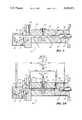
- FIG. 1illustrates a gas analysis cell within a laser resonant cavity in a gas analysis system in a first embodiment of the present invention
- FIG. 2is an enlarged view of the gas analysis cell of the present invention
- FIG. 2Ais an enlarged view of the gas cell of the present invention illustrating the ga flows within the cell.
- a gas analysis cell 10 in accordance with the present inventionis positioned within a resonant cavity of a laser in a gas analysis system.
- the resonant cavityincludes a plasma discharge tube 16 and has a volume which is defined by a first reflector 18 and a second reflector 20.
- the first reflector 18preferably comprises a high reflectivity mirror, i.e., a mirror with a reflectivity greater than 99.99%.
- the reflector 20preferably comprises a second high reflectivity mirror. Alternatively, the second high reflectivity mirror could be coated on the back side of a Littrow prism.
- a Brewster prism 21may be inserted in the cavity to select a particular wavelength of light for circulation through the resonant cavity.
- a lasing gas mixtureis confined within the discharge tube 16 and a Brewster window 22 is positioned at the end of the discharge tube 16 adjacent the output such that the light beam propagating within the cavity enters and exits the discharge tube 16 through the Brewster window 22.
- the gas analysis cell 10is positioned intermediate the Brewster window 22 and second reflector 20 within the laser resonant cavity.
- the analysis cell 10comprises a housing 24 enclosing an analysis chamber 26.
- the analysis cell 10includes two buffer regions 28, 30 on either end of the analysis chamber 26.
- the analysis chamber 26is connected to the source of gas to be analyzed by a gas sample inlet port 34.
- the gas analysis cell 10further comprises a plurality of output channels 36 which form optical passageways between the analysis chamber 26 and the outside of the gas cell 10.
- a first buffer gas input port 40is connected to the buffer region 30 adjacent the Brewster window 22 and a second buffer gas input port 42 is connected to the buffer region 28 adjacent the second reflector 20.
- the cellcomprises a first output port 44 connected to the buffer region 30 at the end of the analysis chamber 26 nearest the Brewster window 22. Output port 44 is positioned intermediate the gas sample inlet port 34 and first buffer gas inlet port 40. A second output port 46 is connected to the buffer region 28 at the end of the analysis chamber nearest the second reflector 20. Output port 46 is positioned intermediate the gas sample inlet port 34 and the second buffer gas inlet port 42.
- a gas sample which is to be analyzedenters the sampling cell 10 through the input port 34 and is contained within the analysis chamber 26.
- the laser discharge tube 16emits a collimated beam of polarized light with a characteristic wavelength dependent upon the type of gas within the discharge tube 16 the orientation of the Brewster prism 21, and the nature of the mirror coating on high reflector mirrors 18,20.
- the light beamtravels an optical path through the Brewster window 22 and through the length of the analysis chamber 26 of the gas analysis cell 10 and is incident upon the second reflector 20.
- the length of the resonant cavityis such that the light beam resonates between the first and second reflectors 18, 20 which define the volume of the resonant cavity.
- the emitted lightpropagates within the resonant cavity, entering and exiting the discharge tube 16 through the Brewster window 22, thereby stimulating further emission of additional excited atoms within the discharge tube and achieving optimum light amplification.
- the Brewster prism 21optimizes the power of a preferred wavelength and polarization state of the laser beam circulating in the resonant cavity.
- the Brewster window 22serves to seal the gas within the discharge tube 16 while also providing polarization control of the light beam by completely transmitting light of a preferred polarization state.
- the light beam circulating in the resonant cavityintercepts the sample of the gas to be analyzed.
- the Raman scattered radiation from the gas sampleis collected over as large a solid angle as possible by the detector channels 36, which are located approximately perpendicular to and on either side of the axis of the laser light beam propagating inside the analysis chamber 26.
- the Raman signalscan then by analyzed with a microprocessor (not shown) associated with the detector channels 36 and, based on this analysis, the identity and concentration of each specific gas comprising the gas sample contained within the analysis chamber 26 can be determined and reported.
- a microprocessornot shown
- a flow of buffer gas 50is introduced into the two buffer gas inlet ports 40, 42 formed in the buffer regions 28, 30 of the cell 10.
- a portion 50A of the flow 50, input through the first buffer gas inlet port 40,is directed past the Brewster window 22 and toward one end of the analysis chamber 26.
- a second portion 50B of the flow 50, input through the second buffer gas inlet port 42,is directed past the end reflector 20 and toward the opposing end of the analysis chamber 26.
- the buffer gas flows 50A and 50Bmix with the gas sample 52 contained within the analysis chamber 26 and forms gas mixtures 54A and 54B.
- the gas mixtures 54A and 54Bthen exit the gas analysis cell 10 through the output ports 44, 46 formed in the housing 24 at either end of the analysis chamber 26.
- the buffer gas flow 50 through the analysis cell 10forms a "dam" which constrains the gas sample 52 to the portion of the analysis chamber 26 located intermediate the analysis chamber outlet ports 44, 46.
- the buffer gas flows 50A and 50Bserve to protect the optical elements, i.e., the Brewster window 22, the second reflector 20, and the Brewster prism 21, of the gas analysis system from contaminants which may be present in the gas sample 52.
- the gas analysis cell 10 illustrated in FIG. 1 and FIG. 2further serves to reduce problems caused by variations in index of refraction and beam steering which often occur as the laser beam propagates through the Brewster window 22.
- the laser beampasses through the Brewster window 22 adjacent the discharge tube 16, it is "steered", i.e., deflected, and exits the Brewster window 22 at an angle which is different from the angle at which it entered if the index of refraction of the gases on the two sides of the window are not equal.
- the angle in reference to the axis of the resonant cavity at which the laser beam emitted from the discharge tube 16 exits the Brewster window 22is dependent upon 1) The indices of refraction of the window material and the gases on either side of the window; and 2) The angle of the plane in which index of refraction changes occur relative to the axis of the laser beam passing through the analysis cell 10. Note, that if this plane is perpendicular to the beam axis, no change in beam direction will occur regardless of differences in indices of refraction. Obviously, the index of refraction of the window material comprising the Brewster window 22 is fixed. However, the index of refraction of the sample gas on the gas cell side of the window will change as the individual components comprising the gases vary in type and concentration.
- the buffer gas flow 50A shown in FIG. 2A immediately in front of the Brewster window 22 along the optical path of the light beamremains constant regardless of what type and concentration of gases comprising the gas sample 52 are introduced into the analysis chamber 26. Since the index of refraction does not change next to the side of the Brewster window 22 adjacent the analysis chamber 26, the angle at which the beam exits the Brewster window is constant and beam steering effects due to the buffer gas are predictable and can be accounted for in the design.
- the index of refraction of the gas sample 52 contained in the analysis chamber 26 of the gas cellstill varies as the concentration of the individual gases comprising the sample varies, and thus, the index of refraction changes where the sample gas mixes with the buffer gas 50 creating the gas mixture 54.
- this change in index of refractionoccurs in a plane which is nominally perpendicular to the optical path of the laser beam and hence, does not cause the beam steering problems which occur when the change in refractive index occurs at Brewster window 22, i.e., in a plane which is not perpendicular to the optical path.
- the buffer gas flow 50can be utilized not only to prevent beam steering, but also to move unavoidable beam steering effects to a location where the effects are no longer deleterious.
- the analysis chamber inlet port 34need not be positioned in the center of the analysis cell as illustrated in FIG. 1 and FIG. 2, there are several advantages associated with this location.
- the flowis introduced immediately into the analysis chamber 26 without having to displace the volumes around the optics 20, 22 at either end of the cell.
- the gas sampleflows past each pair of detector channels 36 sequentially.
- the gas sample 52flows into the center of the analysis chamber 26 and then flows away from the inlet 34 in two directions, toward each end of the chamber 26.
- two pairs of detector channels 36are located immediately adjacent to the gas sample input 34, thereby advantageously decreasing response time by as much as one half compared with the response time of prior art systems wherein the gas sample 52 is introduced at one end of the analysis chamber 26.
- the flow 50When the buffer gas flow 50 is input at relatively low flow rates, the flow generally is laminar rather than turbulent in nature.
- the point inside the analysis cell 10 at which the gas sample 52 mixes with the buffer gas 50 to form the gas mixture 54occurs in the laminar flow region, thereby eliminating turbulent mixing and changes in refractive index, i.e., Schlieren effects which can cause power losses in the transmission of the laser beam.
Landscapes
- Physics & Mathematics (AREA)
- Health & Medical Sciences (AREA)
- Life Sciences & Earth Sciences (AREA)
- Chemical & Material Sciences (AREA)
- Analytical Chemistry (AREA)
- Biochemistry (AREA)
- General Health & Medical Sciences (AREA)
- General Physics & Mathematics (AREA)
- Immunology (AREA)
- Pathology (AREA)
- Optical Measuring Cells (AREA)
- Investigating, Analyzing Materials By Fluorescence Or Luminescence (AREA)
- Investigating Or Analysing Materials By Optical Means (AREA)
Abstract
Description
Claims (12)
Priority Applications (8)
| Application Number | Priority Date | Filing Date | Title |
|---|---|---|---|
| US07/522,533US5153671A (en) | 1990-05-11 | 1990-05-11 | Gas analysis system having buffer gas inputs to protect associated optical elements |
| AU78669/91AAU7866991A (en) | 1990-05-11 | 1991-05-10 | Gas analysis system having buffer gas inputs to protect associated optical elements |
| JP91509171AJPH05507147A (en) | 1990-05-11 | 1991-05-10 | Gas analysis system with buffer gas input to protect integrated optics |
| CA002082657ACA2082657A1 (en) | 1990-05-11 | 1991-05-10 | Gas analysis system having buffer gas inputs to protect associated optical elements |
| EP91909429AEP0527880A1 (en) | 1990-05-11 | 1991-05-10 | Gas analysis system having buffer gas inputs to protect associated optical elements |
| PCT/US1991/003249WO1991018277A1 (en) | 1990-05-11 | 1991-05-10 | Gas analysis system having buffer gas inputs to protect associated optical elements |
| US07/771,625US5135304A (en) | 1990-05-11 | 1991-10-04 | Gas analysis system having buffer gas inputs to protect associated optical elements |
| US07/922,874US5245405A (en) | 1990-05-11 | 1992-07-31 | Constant pressure gas cell |
Applications Claiming Priority (1)
| Application Number | Priority Date | Filing Date | Title |
|---|---|---|---|
| US07/522,533US5153671A (en) | 1990-05-11 | 1990-05-11 | Gas analysis system having buffer gas inputs to protect associated optical elements |
Related Child Applications (1)
| Application Number | Title | Priority Date | Filing Date |
|---|---|---|---|
| US07/771,625Continuation-In-PartUS5135304A (en) | 1990-05-11 | 1991-10-04 | Gas analysis system having buffer gas inputs to protect associated optical elements |
Publications (1)
| Publication Number | Publication Date |
|---|---|
| US5153671Atrue US5153671A (en) | 1992-10-06 |
Family
ID=24081238
Family Applications (1)
| Application Number | Title | Priority Date | Filing Date |
|---|---|---|---|
| US07/522,533Expired - LifetimeUS5153671A (en) | 1990-05-11 | 1990-05-11 | Gas analysis system having buffer gas inputs to protect associated optical elements |
Country Status (6)
| Country | Link |
|---|---|
| US (1) | US5153671A (en) |
| EP (1) | EP0527880A1 (en) |
| JP (1) | JPH05507147A (en) |
| AU (1) | AU7866991A (en) |
| CA (1) | CA2082657A1 (en) |
| WO (1) | WO1991018277A1 (en) |
Cited By (63)
| Publication number | Priority date | Publication date | Assignee | Title |
|---|---|---|---|---|
| US5360980A (en)* | 1993-02-26 | 1994-11-01 | High Yield Technology | Structure and method for providing a gas purge for a vacuum particle sensor installed in a corrosive or coating environment |
| US5452084A (en)* | 1993-03-29 | 1995-09-19 | Albion Instruments, Inc. | Method and apparatus for zero-calibration of a raman spectroscopy system |
| US5521703A (en)* | 1994-10-17 | 1996-05-28 | Albion Instruments, Inc. | Diode laser pumped Raman gas analysis system with reflective hollow tube gas cell |
| US5596404A (en)* | 1994-12-30 | 1997-01-21 | Albion Instruments, Inc. | Raman gas analysis system with flexible web and differential thread for precision optical alignment |
| EP0755104A1 (en) | 1995-07-21 | 1997-01-22 | Hewlett-Packard GmbH | Method for adjusting a laser resonator |
| DE19615333A1 (en)* | 1995-07-24 | 1997-01-30 | Hewlett Packard Co | Gas analyser partic. for human breath - incorporates an in-situ system using carbon di:oxide snow for cleaning optical surfaces and thus allowing the analysis chamber to remain closed |
| US5673109A (en)* | 1996-07-10 | 1997-09-30 | Ohmeda Inc. | System and method for increasing the efficiency of a raman gas analysis system |
| US5703683A (en)* | 1996-05-28 | 1997-12-30 | Ohmeda Inc. | Extruded wobble plate optical alignment device |
| US5929981A (en)* | 1996-06-18 | 1999-07-27 | Ohmeda Inc. | System for monitoring contamination of optical elements in a Raman gas analyzer |
| US6222860B1 (en) | 1999-01-07 | 2001-04-24 | Hewlett-Packard Company | Laser system tolerating disturbances using multiple modes |
| US20100073679A1 (en)* | 2008-09-24 | 2010-03-25 | Rikard Larking | Optical measuring head for a duct gas monitoring system |
| US7875047B2 (en) | 2002-04-19 | 2011-01-25 | Pelikan Technologies, Inc. | Method and apparatus for a multi-use body fluid sampling device with sterility barrier release |
| US7892183B2 (en) | 2002-04-19 | 2011-02-22 | Pelikan Technologies, Inc. | Method and apparatus for body fluid sampling and analyte sensing |
| US7901365B2 (en) | 2002-04-19 | 2011-03-08 | Pelikan Technologies, Inc. | Method and apparatus for penetrating tissue |
| US7909775B2 (en) | 2001-06-12 | 2011-03-22 | Pelikan Technologies, Inc. | Method and apparatus for lancet launching device integrated onto a blood-sampling cartridge |
| US7909774B2 (en) | 2002-04-19 | 2011-03-22 | Pelikan Technologies, Inc. | Method and apparatus for penetrating tissue |
| US7909777B2 (en) | 2002-04-19 | 2011-03-22 | Pelikan Technologies, Inc | Method and apparatus for penetrating tissue |
| US7909778B2 (en) | 2002-04-19 | 2011-03-22 | Pelikan Technologies, Inc. | Method and apparatus for penetrating tissue |
| US7914465B2 (en) | 2002-04-19 | 2011-03-29 | Pelikan Technologies, Inc. | Method and apparatus for penetrating tissue |
| US7976476B2 (en) | 2002-04-19 | 2011-07-12 | Pelikan Technologies, Inc. | Device and method for variable speed lancet |
| US7981055B2 (en) | 2001-06-12 | 2011-07-19 | Pelikan Technologies, Inc. | Tissue penetration device |
| US7981056B2 (en) | 2002-04-19 | 2011-07-19 | Pelikan Technologies, Inc. | Methods and apparatus for lancet actuation |
| US7988645B2 (en) | 2001-06-12 | 2011-08-02 | Pelikan Technologies, Inc. | Self optimizing lancing device with adaptation means to temporal variations in cutaneous properties |
| US8007446B2 (en) | 2002-04-19 | 2011-08-30 | Pelikan Technologies, Inc. | Method and apparatus for penetrating tissue |
| US8062231B2 (en) | 2002-04-19 | 2011-11-22 | Pelikan Technologies, Inc. | Method and apparatus for penetrating tissue |
| US8079960B2 (en) | 2002-04-19 | 2011-12-20 | Pelikan Technologies, Inc. | Methods and apparatus for lancet actuation |
| US8197421B2 (en) | 2002-04-19 | 2012-06-12 | Pelikan Technologies, Inc. | Method and apparatus for penetrating tissue |
| US8221334B2 (en) | 2002-04-19 | 2012-07-17 | Sanofi-Aventis Deutschland Gmbh | Method and apparatus for penetrating tissue |
| US8251921B2 (en) | 2003-06-06 | 2012-08-28 | Sanofi-Aventis Deutschland Gmbh | Method and apparatus for body fluid sampling and analyte sensing |
| US8262614B2 (en) | 2003-05-30 | 2012-09-11 | Pelikan Technologies, Inc. | Method and apparatus for fluid injection |
| US8267870B2 (en) | 2002-04-19 | 2012-09-18 | Sanofi-Aventis Deutschland Gmbh | Method and apparatus for body fluid sampling with hybrid actuation |
| US8282576B2 (en) | 2003-09-29 | 2012-10-09 | Sanofi-Aventis Deutschland Gmbh | Method and apparatus for an improved sample capture device |
| US8296918B2 (en) | 2003-12-31 | 2012-10-30 | Sanofi-Aventis Deutschland Gmbh | Method of manufacturing a fluid sampling device with improved analyte detecting member configuration |
| US8333710B2 (en) | 2002-04-19 | 2012-12-18 | Sanofi-Aventis Deutschland Gmbh | Tissue penetration device |
| US8360992B2 (en) | 2002-04-19 | 2013-01-29 | Sanofi-Aventis Deutschland Gmbh | Method and apparatus for penetrating tissue |
| US8372016B2 (en) | 2002-04-19 | 2013-02-12 | Sanofi-Aventis Deutschland Gmbh | Method and apparatus for body fluid sampling and analyte sensing |
| US8382682B2 (en) | 2002-04-19 | 2013-02-26 | Sanofi-Aventis Deutschland Gmbh | Method and apparatus for penetrating tissue |
| US8435190B2 (en) | 2002-04-19 | 2013-05-07 | Sanofi-Aventis Deutschland Gmbh | Method and apparatus for penetrating tissue |
| US8439872B2 (en) | 1998-03-30 | 2013-05-14 | Sanofi-Aventis Deutschland Gmbh | Apparatus and method for penetration with shaft having a sensor for sensing penetration depth |
| US8556829B2 (en) | 2002-04-19 | 2013-10-15 | Sanofi-Aventis Deutschland Gmbh | Method and apparatus for penetrating tissue |
| US8574895B2 (en) | 2002-12-30 | 2013-11-05 | Sanofi-Aventis Deutschland Gmbh | Method and apparatus using optical techniques to measure analyte levels |
| US8641644B2 (en) | 2000-11-21 | 2014-02-04 | Sanofi-Aventis Deutschland Gmbh | Blood testing apparatus having a rotatable cartridge with multiple lancing elements and testing means |
| US8652831B2 (en) | 2004-12-30 | 2014-02-18 | Sanofi-Aventis Deutschland Gmbh | Method and apparatus for analyte measurement test time |
| US8668656B2 (en) | 2003-12-31 | 2014-03-11 | Sanofi-Aventis Deutschland Gmbh | Method and apparatus for improving fluidic flow and sample capture |
| US8702624B2 (en) | 2006-09-29 | 2014-04-22 | Sanofi-Aventis Deutschland Gmbh | Analyte measurement device with a single shot actuator |
| US8721671B2 (en) | 2001-06-12 | 2014-05-13 | Sanofi-Aventis Deutschland Gmbh | Electric lancet actuator |
| US8760644B2 (en)* | 2012-10-31 | 2014-06-24 | Halliburton Energy Services, Inc. | Systems and methods for cleaning an inline optical fluid analyzer |
| US8784335B2 (en) | 2002-04-19 | 2014-07-22 | Sanofi-Aventis Deutschland Gmbh | Body fluid sampling device with a capacitive sensor |
| US8828203B2 (en) | 2004-05-20 | 2014-09-09 | Sanofi-Aventis Deutschland Gmbh | Printable hydrogels for biosensors |
| US8965476B2 (en) | 2010-04-16 | 2015-02-24 | Sanofi-Aventis Deutschland Gmbh | Tissue penetration device |
| US9144401B2 (en) | 2003-06-11 | 2015-09-29 | Sanofi-Aventis Deutschland Gmbh | Low pain penetrating member |
| US9226699B2 (en) | 2002-04-19 | 2016-01-05 | Sanofi-Aventis Deutschland Gmbh | Body fluid sampling module with a continuous compression tissue interface surface |
| US9248267B2 (en) | 2002-04-19 | 2016-02-02 | Sanofi-Aventis Deustchland Gmbh | Tissue penetration device |
| US9314194B2 (en) | 2002-04-19 | 2016-04-19 | Sanofi-Aventis Deutschland Gmbh | Tissue penetration device |
| US9351680B2 (en) | 2003-10-14 | 2016-05-31 | Sanofi-Aventis Deutschland Gmbh | Method and apparatus for a variable user interface |
| US20160167169A1 (en)* | 2009-11-03 | 2016-06-16 | The Secretary, Department Of Atomic Energy, Govt. Of India | Niobium based superconducting radio frequency(scrf) cavities comprising niobium components joined by laser welding, method and apparatus for manufacturing such cavities |
| US9375169B2 (en) | 2009-01-30 | 2016-06-28 | Sanofi-Aventis Deutschland Gmbh | Cam drive for managing disposable penetrating member actions with a single motor and motor and control system |
| US9386944B2 (en) | 2008-04-11 | 2016-07-12 | Sanofi-Aventis Deutschland Gmbh | Method and apparatus for analyte detecting device |
| US9427532B2 (en) | 2001-06-12 | 2016-08-30 | Sanofi-Aventis Deutschland Gmbh | Tissue penetration device |
| US20170227453A1 (en)* | 2014-08-15 | 2017-08-10 | Tenova Goodfellow Inc. | System and Method for Analyzing Dusty Industrial Off-gas Chemistry |
| US9775553B2 (en) | 2004-06-03 | 2017-10-03 | Sanofi-Aventis Deutschland Gmbh | Method and apparatus for a fluid sampling device |
| US9795747B2 (en) | 2010-06-02 | 2017-10-24 | Sanofi-Aventis Deutschland Gmbh | Methods and apparatus for lancet actuation |
| US9820684B2 (en) | 2004-06-03 | 2017-11-21 | Sanofi-Aventis Deutschland Gmbh | Method and apparatus for a fluid sampling device |
Families Citing this family (4)
| Publication number | Priority date | Publication date | Assignee | Title |
|---|---|---|---|---|
| US5135304A (en)* | 1990-05-11 | 1992-08-04 | Boc Health Care, Inc. | Gas analysis system having buffer gas inputs to protect associated optical elements |
| DE19531263C2 (en)* | 1995-08-25 | 2003-07-03 | Bosch Gmbh Robert | Device for measuring the turbidity of flue gas |
| DE102004028420B3 (en)* | 2004-06-04 | 2006-02-09 | Fraunhofer-Gesellschaft zur Förderung der angewandten Forschung e.V. | Apparatus and method for the optical detection of substances contained in exhaust gases of chemical processes |
| JP6750734B2 (en)* | 2017-04-21 | 2020-09-02 | 株式会社島津製作所 | Flow cell and detector equipped with the flow cell |
Citations (37)
| Publication number | Priority date | Publication date | Assignee | Title |
|---|---|---|---|---|
| US3515482A (en)* | 1967-06-27 | 1970-06-02 | Us Navy | Aerosol photometer with improved electronic circuitry |
| FR2061491A5 (en)* | 1969-09-17 | 1971-06-18 | Commercial Electronics | |
| FR2210291A5 (en)* | 1972-12-07 | 1974-07-05 | Commercial Electronics Inc | |
| US3833305A (en)* | 1969-09-17 | 1974-09-03 | Commercial Electronics Inc | Gas analyzing apparatus |
| US4071298A (en)* | 1974-06-27 | 1978-01-31 | Stanford Research Institute | Laser Raman/fluorescent device for analyzing airborne particles |
| US4113386A (en)* | 1976-09-20 | 1978-09-12 | Climet Instruments Company | Photometer |
| US4225243A (en)* | 1978-06-26 | 1980-09-30 | Measurex Corporation | Gas measuring apparatus with standardization means, and method therefor |
| US4277131A (en)* | 1980-01-29 | 1981-07-07 | The United States Of America As Represented By The Administrator Of The United States Environmental Protection Agency | Antifouling window assembly |
| US4413911A (en)* | 1981-04-24 | 1983-11-08 | Measurex Corporation | Gas analyzer with fluid curtain |
| US4443072A (en)* | 1982-04-05 | 1984-04-17 | The United States Of America As Represented By The United States Department Of Energy | Purged window apparatus utilizing heated purge gas |
| US4515274A (en)* | 1981-12-02 | 1985-05-07 | Coulter Corporation | Particle analyzing and sorting apparatus |
| US4544273A (en)* | 1983-07-29 | 1985-10-01 | Particulate Instruments | Smoke opacity meter |
| JPS60233536A (en)* | 1984-05-04 | 1985-11-20 | Nippon Soken Inc | Light transmission type measuring instrument for black smoke density |
| US4594715A (en)* | 1983-11-17 | 1986-06-10 | Particle Measuring Systems, Inc. | Laser with stabilized external passive cavity |
| US4647780A (en)* | 1983-10-13 | 1987-03-03 | Perkins Engines Group Limited | Apparatus for measuring smoke density |
| US4648714A (en)* | 1985-09-11 | 1987-03-10 | University Of Utah | Molecular gas analysis by Raman scattering in intracavity laser configuration |
| US4649830A (en)* | 1984-09-03 | 1987-03-17 | Sanki Kogyo Kabushiki Kaisha | Clean tunnel conveying structure |
| US4654226A (en)* | 1986-03-03 | 1987-03-31 | The University Of Delaware | Apparatus and method for photochemical vapor deposition |
| US4672620A (en)* | 1986-05-14 | 1987-06-09 | Spectra-Physics, Inc. | Fast axial flow carbon dioxide laser |
| US4676639A (en)* | 1986-01-22 | 1987-06-30 | Biomaterials International, Inc. | Gas cell for raman scattering analysis by laser means |
| US4701096A (en)* | 1986-03-05 | 1987-10-20 | Btu Engineering Corporation | Wafer handling station |
| US4713964A (en)* | 1985-07-24 | 1987-12-22 | Grundig E.M.V. Elektro-Mechanische Versuchsantalt Max Grundig Holland.Stiftung & Co. Kg | Device for optical turbidity measuring of gases |
| US4723063A (en)* | 1985-04-16 | 1988-02-02 | Rofin-Sinar Laser Gmbh | Laser welding apparatus |
| SU1376011A1 (en)* | 1985-06-25 | 1988-02-23 | Всесоюзный научно-исследовательский геологоразведочный нефтяной институт | Portless cell for spectral gas-chr omatographic detection |
| US4746215A (en)* | 1986-04-24 | 1988-05-24 | Pacific Scientific Company | Particle counter air inlet assembly |
| US4784486A (en)* | 1987-10-06 | 1988-11-15 | Albion Instruments | Multi-channel molecular gas analysis by laser-activated Raman light scattering |
| US4784491A (en)* | 1986-06-03 | 1988-11-15 | General Electric Company | System to protect optics against dirty environments |
| US4786188A (en)* | 1986-02-27 | 1988-11-22 | Rosemont Inc. | Purge air system for a combustion instrument |
| US4787750A (en)* | 1987-04-08 | 1988-11-29 | Westinghouse Electric Corp. | Gas spectrometer construction having an improved alignment feature |
| US4837443A (en)* | 1987-10-15 | 1989-06-06 | The Perkin-Elmer Corporation | Guard ring for a differentially pumped seal apparatus |
| US4840226A (en)* | 1987-08-10 | 1989-06-20 | The United States Of America As Represented By The United States Department Of Energy | Corrosive resistant heat exchanger |
| US4845426A (en)* | 1987-05-20 | 1989-07-04 | Signatone Corporation | Temperature conditioner for tests of unpackaged semiconductors |
| US4846102A (en)* | 1987-06-24 | 1989-07-11 | Epsilon Technology, Inc. | Reaction chambers for CVD systems |
| US4924097A (en)* | 1984-06-22 | 1990-05-08 | Georgia Tech Rss. Corp | Monodisperse aerosol generator for use with infrared spectrometry |
| US4940327A (en)* | 1988-10-25 | 1990-07-10 | Trc Companies Inc. | Method and apparatus for real time asbestos aerosol monitoring |
| US4983038A (en)* | 1987-04-08 | 1991-01-08 | Hitachi, Ltd. | Sheath flow type flow-cell device |
| US5011286A (en)* | 1989-08-03 | 1991-04-30 | Met One, Inc. | Multisensor particle counter utilizing a single energy source |
- 1990
- 1990-05-11USUS07/522,533patent/US5153671A/ennot_activeExpired - Lifetime
- 1991
- 1991-05-10AUAU78669/91Apatent/AU7866991A/ennot_activeAbandoned
- 1991-05-10EPEP91909429Apatent/EP0527880A1/ennot_activeCeased
- 1991-05-10CACA002082657Apatent/CA2082657A1/ennot_activeAbandoned
- 1991-05-10JPJP91509171Apatent/JPH05507147A/enactivePending
- 1991-05-10WOPCT/US1991/003249patent/WO1991018277A1/ennot_activeApplication Discontinuation
Patent Citations (37)
| Publication number | Priority date | Publication date | Assignee | Title |
|---|---|---|---|---|
| US3515482A (en)* | 1967-06-27 | 1970-06-02 | Us Navy | Aerosol photometer with improved electronic circuitry |
| FR2061491A5 (en)* | 1969-09-17 | 1971-06-18 | Commercial Electronics | |
| US3833305A (en)* | 1969-09-17 | 1974-09-03 | Commercial Electronics Inc | Gas analyzing apparatus |
| FR2210291A5 (en)* | 1972-12-07 | 1974-07-05 | Commercial Electronics Inc | |
| US4071298A (en)* | 1974-06-27 | 1978-01-31 | Stanford Research Institute | Laser Raman/fluorescent device for analyzing airborne particles |
| US4113386A (en)* | 1976-09-20 | 1978-09-12 | Climet Instruments Company | Photometer |
| US4225243A (en)* | 1978-06-26 | 1980-09-30 | Measurex Corporation | Gas measuring apparatus with standardization means, and method therefor |
| US4277131A (en)* | 1980-01-29 | 1981-07-07 | The United States Of America As Represented By The Administrator Of The United States Environmental Protection Agency | Antifouling window assembly |
| US4413911A (en)* | 1981-04-24 | 1983-11-08 | Measurex Corporation | Gas analyzer with fluid curtain |
| US4515274A (en)* | 1981-12-02 | 1985-05-07 | Coulter Corporation | Particle analyzing and sorting apparatus |
| US4443072A (en)* | 1982-04-05 | 1984-04-17 | The United States Of America As Represented By The United States Department Of Energy | Purged window apparatus utilizing heated purge gas |
| US4544273A (en)* | 1983-07-29 | 1985-10-01 | Particulate Instruments | Smoke opacity meter |
| US4647780A (en)* | 1983-10-13 | 1987-03-03 | Perkins Engines Group Limited | Apparatus for measuring smoke density |
| US4594715A (en)* | 1983-11-17 | 1986-06-10 | Particle Measuring Systems, Inc. | Laser with stabilized external passive cavity |
| JPS60233536A (en)* | 1984-05-04 | 1985-11-20 | Nippon Soken Inc | Light transmission type measuring instrument for black smoke density |
| US4924097A (en)* | 1984-06-22 | 1990-05-08 | Georgia Tech Rss. Corp | Monodisperse aerosol generator for use with infrared spectrometry |
| US4649830A (en)* | 1984-09-03 | 1987-03-17 | Sanki Kogyo Kabushiki Kaisha | Clean tunnel conveying structure |
| US4723063A (en)* | 1985-04-16 | 1988-02-02 | Rofin-Sinar Laser Gmbh | Laser welding apparatus |
| SU1376011A1 (en)* | 1985-06-25 | 1988-02-23 | Всесоюзный научно-исследовательский геологоразведочный нефтяной институт | Portless cell for spectral gas-chr omatographic detection |
| US4713964A (en)* | 1985-07-24 | 1987-12-22 | Grundig E.M.V. Elektro-Mechanische Versuchsantalt Max Grundig Holland.Stiftung & Co. Kg | Device for optical turbidity measuring of gases |
| US4648714A (en)* | 1985-09-11 | 1987-03-10 | University Of Utah | Molecular gas analysis by Raman scattering in intracavity laser configuration |
| US4676639A (en)* | 1986-01-22 | 1987-06-30 | Biomaterials International, Inc. | Gas cell for raman scattering analysis by laser means |
| US4786188A (en)* | 1986-02-27 | 1988-11-22 | Rosemont Inc. | Purge air system for a combustion instrument |
| US4654226A (en)* | 1986-03-03 | 1987-03-31 | The University Of Delaware | Apparatus and method for photochemical vapor deposition |
| US4701096A (en)* | 1986-03-05 | 1987-10-20 | Btu Engineering Corporation | Wafer handling station |
| US4746215A (en)* | 1986-04-24 | 1988-05-24 | Pacific Scientific Company | Particle counter air inlet assembly |
| US4672620A (en)* | 1986-05-14 | 1987-06-09 | Spectra-Physics, Inc. | Fast axial flow carbon dioxide laser |
| US4784491A (en)* | 1986-06-03 | 1988-11-15 | General Electric Company | System to protect optics against dirty environments |
| US4983038A (en)* | 1987-04-08 | 1991-01-08 | Hitachi, Ltd. | Sheath flow type flow-cell device |
| US4787750A (en)* | 1987-04-08 | 1988-11-29 | Westinghouse Electric Corp. | Gas spectrometer construction having an improved alignment feature |
| US4845426A (en)* | 1987-05-20 | 1989-07-04 | Signatone Corporation | Temperature conditioner for tests of unpackaged semiconductors |
| US4846102A (en)* | 1987-06-24 | 1989-07-11 | Epsilon Technology, Inc. | Reaction chambers for CVD systems |
| US4840226A (en)* | 1987-08-10 | 1989-06-20 | The United States Of America As Represented By The United States Department Of Energy | Corrosive resistant heat exchanger |
| US4784486A (en)* | 1987-10-06 | 1988-11-15 | Albion Instruments | Multi-channel molecular gas analysis by laser-activated Raman light scattering |
| US4837443A (en)* | 1987-10-15 | 1989-06-06 | The Perkin-Elmer Corporation | Guard ring for a differentially pumped seal apparatus |
| US4940327A (en)* | 1988-10-25 | 1990-07-10 | Trc Companies Inc. | Method and apparatus for real time asbestos aerosol monitoring |
| US5011286A (en)* | 1989-08-03 | 1991-04-30 | Met One, Inc. | Multisensor particle counter utilizing a single energy source |
Cited By (128)
| Publication number | Priority date | Publication date | Assignee | Title |
|---|---|---|---|---|
| US5360980A (en)* | 1993-02-26 | 1994-11-01 | High Yield Technology | Structure and method for providing a gas purge for a vacuum particle sensor installed in a corrosive or coating environment |
| US5452084A (en)* | 1993-03-29 | 1995-09-19 | Albion Instruments, Inc. | Method and apparatus for zero-calibration of a raman spectroscopy system |
| US5521703A (en)* | 1994-10-17 | 1996-05-28 | Albion Instruments, Inc. | Diode laser pumped Raman gas analysis system with reflective hollow tube gas cell |
| US5818579A (en)* | 1994-12-30 | 1998-10-06 | Ohmeda Inc. | Raman gas analysis system with cavity/boss assembly for precision optical alignment |
| US5912734A (en)* | 1994-12-30 | 1999-06-15 | Ohmeda Inc. | Raman gas analysis system with ball and socket assembly for precision optical alignment |
| US5596404A (en)* | 1994-12-30 | 1997-01-21 | Albion Instruments, Inc. | Raman gas analysis system with flexible web and differential thread for precision optical alignment |
| EP0755104A1 (en) | 1995-07-21 | 1997-01-22 | Hewlett-Packard GmbH | Method for adjusting a laser resonator |
| DE19615333A1 (en)* | 1995-07-24 | 1997-01-30 | Hewlett Packard Co | Gas analyser partic. for human breath - incorporates an in-situ system using carbon di:oxide snow for cleaning optical surfaces and thus allowing the analysis chamber to remain closed |
| US5720650A (en)* | 1995-07-24 | 1998-02-24 | Hewlett-Packard Company | Gas analyzer with arrangement for spray-cleaning optical element |
| US5703683A (en)* | 1996-05-28 | 1997-12-30 | Ohmeda Inc. | Extruded wobble plate optical alignment device |
| US5929981A (en)* | 1996-06-18 | 1999-07-27 | Ohmeda Inc. | System for monitoring contamination of optical elements in a Raman gas analyzer |
| US5673109A (en)* | 1996-07-10 | 1997-09-30 | Ohmeda Inc. | System and method for increasing the efficiency of a raman gas analysis system |
| US8439872B2 (en) | 1998-03-30 | 2013-05-14 | Sanofi-Aventis Deutschland Gmbh | Apparatus and method for penetration with shaft having a sensor for sensing penetration depth |
| US6222860B1 (en) | 1999-01-07 | 2001-04-24 | Hewlett-Packard Company | Laser system tolerating disturbances using multiple modes |
| US8641644B2 (en) | 2000-11-21 | 2014-02-04 | Sanofi-Aventis Deutschland Gmbh | Blood testing apparatus having a rotatable cartridge with multiple lancing elements and testing means |
| US8721671B2 (en) | 2001-06-12 | 2014-05-13 | Sanofi-Aventis Deutschland Gmbh | Electric lancet actuator |
| US9937298B2 (en) | 2001-06-12 | 2018-04-10 | Sanofi-Aventis Deutschland Gmbh | Tissue penetration device |
| US7909775B2 (en) | 2001-06-12 | 2011-03-22 | Pelikan Technologies, Inc. | Method and apparatus for lancet launching device integrated onto a blood-sampling cartridge |
| US9427532B2 (en) | 2001-06-12 | 2016-08-30 | Sanofi-Aventis Deutschland Gmbh | Tissue penetration device |
| US8845550B2 (en) | 2001-06-12 | 2014-09-30 | Sanofi-Aventis Deutschland Gmbh | Tissue penetration device |
| US8206317B2 (en) | 2001-06-12 | 2012-06-26 | Sanofi-Aventis Deutschland Gmbh | Tissue penetration device |
| US8679033B2 (en) | 2001-06-12 | 2014-03-25 | Sanofi-Aventis Deutschland Gmbh | Tissue penetration device |
| US9694144B2 (en) | 2001-06-12 | 2017-07-04 | Sanofi-Aventis Deutschland Gmbh | Sampling module device and method |
| US8641643B2 (en) | 2001-06-12 | 2014-02-04 | Sanofi-Aventis Deutschland Gmbh | Sampling module device and method |
| US8622930B2 (en) | 2001-06-12 | 2014-01-07 | Sanofi-Aventis Deutschland Gmbh | Tissue penetration device |
| US7981055B2 (en) | 2001-06-12 | 2011-07-19 | Pelikan Technologies, Inc. | Tissue penetration device |
| US9802007B2 (en) | 2001-06-12 | 2017-10-31 | Sanofi-Aventis Deutschland Gmbh | Methods and apparatus for lancet actuation |
| US7988645B2 (en) | 2001-06-12 | 2011-08-02 | Pelikan Technologies, Inc. | Self optimizing lancing device with adaptation means to temporal variations in cutaneous properties |
| US8206319B2 (en) | 2001-06-12 | 2012-06-26 | Sanofi-Aventis Deutschland Gmbh | Tissue penetration device |
| US8382683B2 (en) | 2001-06-12 | 2013-02-26 | Sanofi-Aventis Deutschland Gmbh | Tissue penetration device |
| US8016774B2 (en) | 2001-06-12 | 2011-09-13 | Pelikan Technologies, Inc. | Tissue penetration device |
| US8360991B2 (en) | 2001-06-12 | 2013-01-29 | Sanofi-Aventis Deutschland Gmbh | Tissue penetration device |
| US8343075B2 (en) | 2001-06-12 | 2013-01-01 | Sanofi-Aventis Deutschland Gmbh | Tissue penetration device |
| US8123700B2 (en) | 2001-06-12 | 2012-02-28 | Pelikan Technologies, Inc. | Method and apparatus for lancet launching device integrated onto a blood-sampling cartridge |
| US8337421B2 (en) | 2001-06-12 | 2012-12-25 | Sanofi-Aventis Deutschland Gmbh | Tissue penetration device |
| US8162853B2 (en) | 2001-06-12 | 2012-04-24 | Pelikan Technologies, Inc. | Tissue penetration device |
| US8282577B2 (en) | 2001-06-12 | 2012-10-09 | Sanofi-Aventis Deutschland Gmbh | Method and apparatus for lancet launching device integrated onto a blood-sampling cartridge |
| US8216154B2 (en) | 2001-06-12 | 2012-07-10 | Sanofi-Aventis Deutschland Gmbh | Tissue penetration device |
| US8211037B2 (en) | 2001-06-12 | 2012-07-03 | Pelikan Technologies, Inc. | Tissue penetration device |
| US9560993B2 (en) | 2001-11-21 | 2017-02-07 | Sanofi-Aventis Deutschland Gmbh | Blood testing apparatus having a rotatable cartridge with multiple lancing elements and testing means |
| US8403864B2 (en) | 2002-04-19 | 2013-03-26 | Sanofi-Aventis Deutschland Gmbh | Method and apparatus for penetrating tissue |
| US8690796B2 (en) | 2002-04-19 | 2014-04-08 | Sanofi-Aventis Deutschland Gmbh | Method and apparatus for penetrating tissue |
| US8197421B2 (en) | 2002-04-19 | 2012-06-12 | Pelikan Technologies, Inc. | Method and apparatus for penetrating tissue |
| US8221334B2 (en) | 2002-04-19 | 2012-07-17 | Sanofi-Aventis Deutschland Gmbh | Method and apparatus for penetrating tissue |
| US8235915B2 (en) | 2002-04-19 | 2012-08-07 | Sanofi-Aventis Deutschland Gmbh | Method and apparatus for penetrating tissue |
| US9907502B2 (en) | 2002-04-19 | 2018-03-06 | Sanofi-Aventis Deutschland Gmbh | Method and apparatus for penetrating tissue |
| US9839386B2 (en) | 2002-04-19 | 2017-12-12 | Sanofi-Aventis Deustschland Gmbh | Body fluid sampling device with capacitive sensor |
| US8267870B2 (en) | 2002-04-19 | 2012-09-18 | Sanofi-Aventis Deutschland Gmbh | Method and apparatus for body fluid sampling with hybrid actuation |
| US7875047B2 (en) | 2002-04-19 | 2011-01-25 | Pelikan Technologies, Inc. | Method and apparatus for a multi-use body fluid sampling device with sterility barrier release |
| US9795334B2 (en) | 2002-04-19 | 2017-10-24 | Sanofi-Aventis Deutschland Gmbh | Method and apparatus for penetrating tissue |
| US8197423B2 (en) | 2002-04-19 | 2012-06-12 | Pelikan Technologies, Inc. | Method and apparatus for penetrating tissue |
| US9724021B2 (en) | 2002-04-19 | 2017-08-08 | Sanofi-Aventis Deutschland Gmbh | Method and apparatus for penetrating tissue |
| US8333710B2 (en) | 2002-04-19 | 2012-12-18 | Sanofi-Aventis Deutschland Gmbh | Tissue penetration device |
| US8337419B2 (en) | 2002-04-19 | 2012-12-25 | Sanofi-Aventis Deutschland Gmbh | Tissue penetration device |
| US8337420B2 (en) | 2002-04-19 | 2012-12-25 | Sanofi-Aventis Deutschland Gmbh | Tissue penetration device |
| US8157748B2 (en) | 2002-04-19 | 2012-04-17 | Pelikan Technologies, Inc. | Methods and apparatus for lancet actuation |
| US8079960B2 (en) | 2002-04-19 | 2011-12-20 | Pelikan Technologies, Inc. | Methods and apparatus for lancet actuation |
| US8062231B2 (en) | 2002-04-19 | 2011-11-22 | Pelikan Technologies, Inc. | Method and apparatus for penetrating tissue |
| US8360992B2 (en) | 2002-04-19 | 2013-01-29 | Sanofi-Aventis Deutschland Gmbh | Method and apparatus for penetrating tissue |
| US8366637B2 (en) | 2002-04-19 | 2013-02-05 | Sanofi-Aventis Deutschland Gmbh | Method and apparatus for penetrating tissue |
| US8372016B2 (en) | 2002-04-19 | 2013-02-12 | Sanofi-Aventis Deutschland Gmbh | Method and apparatus for body fluid sampling and analyte sensing |
| US8007446B2 (en) | 2002-04-19 | 2011-08-30 | Pelikan Technologies, Inc. | Method and apparatus for penetrating tissue |
| US8382682B2 (en) | 2002-04-19 | 2013-02-26 | Sanofi-Aventis Deutschland Gmbh | Method and apparatus for penetrating tissue |
| US8388551B2 (en) | 2002-04-19 | 2013-03-05 | Sanofi-Aventis Deutschland Gmbh | Method and apparatus for multi-use body fluid sampling device with sterility barrier release |
| US7988644B2 (en) | 2002-04-19 | 2011-08-02 | Pelikan Technologies, Inc. | Method and apparatus for a multi-use body fluid sampling device with sterility barrier release |
| US8414503B2 (en) | 2002-04-19 | 2013-04-09 | Sanofi-Aventis Deutschland Gmbh | Methods and apparatus for lancet actuation |
| US8430828B2 (en) | 2002-04-19 | 2013-04-30 | Sanofi-Aventis Deutschland Gmbh | Method and apparatus for a multi-use body fluid sampling device with sterility barrier release |
| US8435190B2 (en) | 2002-04-19 | 2013-05-07 | Sanofi-Aventis Deutschland Gmbh | Method and apparatus for penetrating tissue |
| US7981056B2 (en) | 2002-04-19 | 2011-07-19 | Pelikan Technologies, Inc. | Methods and apparatus for lancet actuation |
| US8491500B2 (en) | 2002-04-19 | 2013-07-23 | Sanofi-Aventis Deutschland Gmbh | Methods and apparatus for lancet actuation |
| US8496601B2 (en) | 2002-04-19 | 2013-07-30 | Sanofi-Aventis Deutschland Gmbh | Methods and apparatus for lancet actuation |
| US8556829B2 (en) | 2002-04-19 | 2013-10-15 | Sanofi-Aventis Deutschland Gmbh | Method and apparatus for penetrating tissue |
| US8562545B2 (en) | 2002-04-19 | 2013-10-22 | Sanofi-Aventis Deutschland Gmbh | Tissue penetration device |
| US7892183B2 (en) | 2002-04-19 | 2011-02-22 | Pelikan Technologies, Inc. | Method and apparatus for body fluid sampling and analyte sensing |
| US8574168B2 (en) | 2002-04-19 | 2013-11-05 | Sanofi-Aventis Deutschland Gmbh | Method and apparatus for a multi-use body fluid sampling device with analyte sensing |
| US8579831B2 (en) | 2002-04-19 | 2013-11-12 | Sanofi-Aventis Deutschland Gmbh | Method and apparatus for penetrating tissue |
| US7976476B2 (en) | 2002-04-19 | 2011-07-12 | Pelikan Technologies, Inc. | Device and method for variable speed lancet |
| US8636673B2 (en) | 2002-04-19 | 2014-01-28 | Sanofi-Aventis Deutschland Gmbh | Tissue penetration device |
| US7959582B2 (en) | 2002-04-19 | 2011-06-14 | Pelikan Technologies, Inc. | Method and apparatus for penetrating tissue |
| US7938787B2 (en) | 2002-04-19 | 2011-05-10 | Pelikan Technologies, Inc. | Method and apparatus for penetrating tissue |
| US7901365B2 (en) | 2002-04-19 | 2011-03-08 | Pelikan Technologies, Inc. | Method and apparatus for penetrating tissue |
| US9498160B2 (en) | 2002-04-19 | 2016-11-22 | Sanofi-Aventis Deutschland Gmbh | Method for penetrating tissue |
| US7914465B2 (en) | 2002-04-19 | 2011-03-29 | Pelikan Technologies, Inc. | Method and apparatus for penetrating tissue |
| US8202231B2 (en) | 2002-04-19 | 2012-06-19 | Sanofi-Aventis Deutschland Gmbh | Method and apparatus for penetrating tissue |
| US7909774B2 (en) | 2002-04-19 | 2011-03-22 | Pelikan Technologies, Inc. | Method and apparatus for penetrating tissue |
| US7909778B2 (en) | 2002-04-19 | 2011-03-22 | Pelikan Technologies, Inc. | Method and apparatus for penetrating tissue |
| US9339612B2 (en) | 2002-04-19 | 2016-05-17 | Sanofi-Aventis Deutschland Gmbh | Tissue penetration device |
| US8784335B2 (en) | 2002-04-19 | 2014-07-22 | Sanofi-Aventis Deutschland Gmbh | Body fluid sampling device with a capacitive sensor |
| US8808201B2 (en) | 2002-04-19 | 2014-08-19 | Sanofi-Aventis Deutschland Gmbh | Methods and apparatus for penetrating tissue |
| US9314194B2 (en) | 2002-04-19 | 2016-04-19 | Sanofi-Aventis Deutschland Gmbh | Tissue penetration device |
| US8845549B2 (en) | 2002-04-19 | 2014-09-30 | Sanofi-Aventis Deutschland Gmbh | Method for penetrating tissue |
| US7909777B2 (en) | 2002-04-19 | 2011-03-22 | Pelikan Technologies, Inc | Method and apparatus for penetrating tissue |
| US8905945B2 (en) | 2002-04-19 | 2014-12-09 | Dominique M. Freeman | Method and apparatus for penetrating tissue |
| US9248267B2 (en) | 2002-04-19 | 2016-02-02 | Sanofi-Aventis Deustchland Gmbh | Tissue penetration device |
| US9226699B2 (en) | 2002-04-19 | 2016-01-05 | Sanofi-Aventis Deutschland Gmbh | Body fluid sampling module with a continuous compression tissue interface surface |
| US9186468B2 (en) | 2002-04-19 | 2015-11-17 | Sanofi-Aventis Deutschland Gmbh | Method and apparatus for penetrating tissue |
| US9072842B2 (en) | 2002-04-19 | 2015-07-07 | Sanofi-Aventis Deutschland Gmbh | Method and apparatus for penetrating tissue |
| US9089294B2 (en) | 2002-04-19 | 2015-07-28 | Sanofi-Aventis Deutschland Gmbh | Analyte measurement device with a single shot actuator |
| US9089678B2 (en) | 2002-04-19 | 2015-07-28 | Sanofi-Aventis Deutschland Gmbh | Method and apparatus for penetrating tissue |
| US9034639B2 (en) | 2002-12-30 | 2015-05-19 | Sanofi-Aventis Deutschland Gmbh | Method and apparatus using optical techniques to measure analyte levels |
| US8574895B2 (en) | 2002-12-30 | 2013-11-05 | Sanofi-Aventis Deutschland Gmbh | Method and apparatus using optical techniques to measure analyte levels |
| US8262614B2 (en) | 2003-05-30 | 2012-09-11 | Pelikan Technologies, Inc. | Method and apparatus for fluid injection |
| US8251921B2 (en) | 2003-06-06 | 2012-08-28 | Sanofi-Aventis Deutschland Gmbh | Method and apparatus for body fluid sampling and analyte sensing |
| US9144401B2 (en) | 2003-06-11 | 2015-09-29 | Sanofi-Aventis Deutschland Gmbh | Low pain penetrating member |
| US10034628B2 (en) | 2003-06-11 | 2018-07-31 | Sanofi-Aventis Deutschland Gmbh | Low pain penetrating member |
| US8945910B2 (en) | 2003-09-29 | 2015-02-03 | Sanofi-Aventis Deutschland Gmbh | Method and apparatus for an improved sample capture device |
| US8282576B2 (en) | 2003-09-29 | 2012-10-09 | Sanofi-Aventis Deutschland Gmbh | Method and apparatus for an improved sample capture device |
| US9351680B2 (en) | 2003-10-14 | 2016-05-31 | Sanofi-Aventis Deutschland Gmbh | Method and apparatus for a variable user interface |
| US9561000B2 (en) | 2003-12-31 | 2017-02-07 | Sanofi-Aventis Deutschland Gmbh | Method and apparatus for improving fluidic flow and sample capture |
| US8296918B2 (en) | 2003-12-31 | 2012-10-30 | Sanofi-Aventis Deutschland Gmbh | Method of manufacturing a fluid sampling device with improved analyte detecting member configuration |
| US8668656B2 (en) | 2003-12-31 | 2014-03-11 | Sanofi-Aventis Deutschland Gmbh | Method and apparatus for improving fluidic flow and sample capture |
| US9261476B2 (en) | 2004-05-20 | 2016-02-16 | Sanofi Sa | Printable hydrogel for biosensors |
| US8828203B2 (en) | 2004-05-20 | 2014-09-09 | Sanofi-Aventis Deutschland Gmbh | Printable hydrogels for biosensors |
| US9820684B2 (en) | 2004-06-03 | 2017-11-21 | Sanofi-Aventis Deutschland Gmbh | Method and apparatus for a fluid sampling device |
| US9775553B2 (en) | 2004-06-03 | 2017-10-03 | Sanofi-Aventis Deutschland Gmbh | Method and apparatus for a fluid sampling device |
| US8652831B2 (en) | 2004-12-30 | 2014-02-18 | Sanofi-Aventis Deutschland Gmbh | Method and apparatus for analyte measurement test time |
| US8702624B2 (en) | 2006-09-29 | 2014-04-22 | Sanofi-Aventis Deutschland Gmbh | Analyte measurement device with a single shot actuator |
| US9386944B2 (en) | 2008-04-11 | 2016-07-12 | Sanofi-Aventis Deutschland Gmbh | Method and apparatus for analyte detecting device |
| US8274658B2 (en)* | 2008-09-24 | 2012-09-25 | Siemens Aktiengesellschaft | Optical measuring head for a duct gas monitoring system |
| US20100073679A1 (en)* | 2008-09-24 | 2010-03-25 | Rikard Larking | Optical measuring head for a duct gas monitoring system |
| US9375169B2 (en) | 2009-01-30 | 2016-06-28 | Sanofi-Aventis Deutschland Gmbh | Cam drive for managing disposable penetrating member actions with a single motor and motor and control system |
| US20160167169A1 (en)* | 2009-11-03 | 2016-06-16 | The Secretary, Department Of Atomic Energy, Govt. Of India | Niobium based superconducting radio frequency(scrf) cavities comprising niobium components joined by laser welding, method and apparatus for manufacturing such cavities |
| US8965476B2 (en) | 2010-04-16 | 2015-02-24 | Sanofi-Aventis Deutschland Gmbh | Tissue penetration device |
| US9795747B2 (en) | 2010-06-02 | 2017-10-24 | Sanofi-Aventis Deutschland Gmbh | Methods and apparatus for lancet actuation |
| US8760644B2 (en)* | 2012-10-31 | 2014-06-24 | Halliburton Energy Services, Inc. | Systems and methods for cleaning an inline optical fluid analyzer |
| US20170227453A1 (en)* | 2014-08-15 | 2017-08-10 | Tenova Goodfellow Inc. | System and Method for Analyzing Dusty Industrial Off-gas Chemistry |
| US10161851B2 (en)* | 2014-08-15 | 2018-12-25 | Tenova Goodfellow Inc. | System and method for analyzing dusty industrial off-gas chemistry |
| US10648901B2 (en) | 2014-08-15 | 2020-05-12 | Tenova Goodfellow Inc. | System and method for analyzing dusty industrial off-gas chemistry |
Also Published As
| Publication number | Publication date |
|---|---|
| CA2082657A1 (en) | 1991-11-12 |
| JPH05507147A (en) | 1993-10-14 |
| EP0527880A1 (en) | 1993-02-24 |
| AU7866991A (en) | 1991-12-10 |
| WO1991018277A1 (en) | 1991-11-28 |
Similar Documents
| Publication | Publication Date | Title |
|---|---|---|
| US5153671A (en) | Gas analysis system having buffer gas inputs to protect associated optical elements | |
| EP0606384B1 (en) | Gas analysis system having buffer gas inputs to protect associated optical elements | |
| US5245405A (en) | Constant pressure gas cell | |
| CA2204587A1 (en) | System for monitoring contamination of optical elements in a raman gas analyzer | |
| US5528040A (en) | Ring-down cavity spectroscopy cell using continuous wave excitation for trace species detection | |
| US5452084A (en) | Method and apparatus for zero-calibration of a raman spectroscopy system | |
| EP0708323A2 (en) | Diode laser pumped raman gas analysis system with reflective hollow tube gas cell | |
| US7595882B1 (en) | Hollow-core waveguide-based raman systems and methods | |
| JP3228423B2 (en) | Gas detection system and gas detection method | |
| CA1254281A (en) | Method and apparatus for the detection and measurement of gases | |
| KR100401035B1 (en) | Contaminant identification and concentration determination by monitoring the temporal characteristics of an intracavity laser | |
| US5689114A (en) | Gas analyzing apparatus | |
| CA3025935A1 (en) | Photothermal interferometry apparatus and method | |
| US4630923A (en) | Fiberoptic spectrophotometer | |
| WO1997009607A9 (en) | Ultra-sensitive detection of contaminants in gas via intracavity laser spectroscopy (ils) | |
| CN1890555A (en) | Device and method of trace gas analysis using cavity ring-down spectroscopy | |
| CA1122812A (en) | Gas measuring apparatus with standardization means, and method therefor | |
| KR20010110748A (en) | Analysis apparatus | |
| US20100294951A1 (en) | Sensitive gas-phase flourimeter at ambient pressure for nitrogen dioxide | |
| US5673109A (en) | System and method for increasing the efficiency of a raman gas analysis system | |
| Hercher et al. | An efficient intracavity laser Raman spectrometer | |
| JP3165956B2 (en) | Particle measurement device | |
| SU1303908A1 (en) | Device for laser atom absorption and molecular absorption analysis | |
| EP0826957A1 (en) | Gas analyzing apparatus | |
| Wilhelmi | Infrared gas monitoring with high-sensitivity, stability, and specificity |
Legal Events
| Date | Code | Title | Description |
|---|---|---|---|
| AS | Assignment | Owner name:ALBION INSTRUMENTS, A CORP OF UTAH, UTAH Free format text:ASSIGNMENT OF ASSIGNORS INTEREST.;ASSIGNOR:MILES, SCOTT D.;REEL/FRAME:005320/0840 Effective date:19900510 | |
| AS | Assignment | Owner name:ALBION INSTRUMENTS, INC. Free format text:CHANGE OF NAME;ASSIGNOR:ALBION INSTRUMENTS;REEL/FRAME:006104/0761 Effective date:19901010 | |
| AS | Assignment | Owner name:BOC HEALTH CARE, INC. A CORPORATION OF DE Free format text:ASSIGNMENT OF ASSIGNORS INTEREST.;ASSIGNOR:ALBION INSTRUMENTS, INC., A CORPORATION OF UT;REEL/FRAME:006101/0791 Effective date:19920504 | |
| STCF | Information on status: patent grant | Free format text:PATENTED CASE | |
| AS | Assignment | Owner name:ALBION INSTRUMENTS, INC., UTAH Free format text:RECISSION OF ASSIGNMENT BY MUTUAL CONSENT;ASSIGNOR:BOC HEALTH CARE, INC.;REEL/FRAME:006721/0662 Effective date:19930929 | |
| FEPP | Fee payment procedure | Free format text:PAYOR NUMBER ASSIGNED (ORIGINAL EVENT CODE: ASPN); ENTITY STATUS OF PATENT OWNER: LARGE ENTITY | |
| FPAY | Fee payment | Year of fee payment:4 | |
| AS | Assignment | Owner name:OHMEDA INC., COLORADO Free format text:ASSIGNMENT OF ASSIGNORS INTEREST;ASSIGNOR:ALBION INSTRUMENTS, INC.;REEL/FRAME:009624/0235 Effective date:19970911 | |
| AS | Assignment | Owner name:DATEX-OHMEDA, INC., MASSACHUSETTS Free format text:MERGER;ASSIGNOR:OHMEDA, INC.;REEL/FRAME:009866/0245 Effective date:19981218 | |
| FPAY | Fee payment | Year of fee payment:8 | |
| FEPP | Fee payment procedure | Free format text:PAYOR NUMBER ASSIGNED (ORIGINAL EVENT CODE: ASPN); ENTITY STATUS OF PATENT OWNER: LARGE ENTITY Free format text:PAYER NUMBER DE-ASSIGNED (ORIGINAL EVENT CODE: RMPN); ENTITY STATUS OF PATENT OWNER: LARGE ENTITY | |
| FPAY | Fee payment | Year of fee payment:12 |