US5153621A - Optical system for projecting multiple images in adjoining relation without illuminance discontinuities - Google Patents
Optical system for projecting multiple images in adjoining relation without illuminance discontinuitiesDownload PDFInfo
- Publication number
- US5153621A US5153621AUS07/785,921US78592191AUS5153621AUS 5153621 AUS5153621 AUS 5153621AUS 78592191 AUS78592191 AUS 78592191AUS 5153621 AUS5153621 AUS 5153621A
- Authority
- US
- United States
- Prior art keywords
- lens
- image
- discrete
- optical system
- light rays
- Prior art date
- Legal status (The legal status is an assumption and is not a legal conclusion. Google has not performed a legal analysis and makes no representation as to the accuracy of the status listed.)
- Expired - Fee Related
Links
- 230000003287optical effectEffects0.000titleclaimsabstractdescription68
- 238000009125cardiac resynchronization therapyMethods0.000description2
- 238000005286illuminationMethods0.000description2
- 239000004973liquid crystal related substanceSubstances0.000description2
- 238000010276constructionMethods0.000description1
- 239000013078crystalSubstances0.000description1
- 230000000694effectsEffects0.000description1
- 238000009434installationMethods0.000description1
- 230000002452interceptive effectEffects0.000description1
- 239000000203mixtureSubstances0.000description1
- 238000012986modificationMethods0.000description1
- 230000004048modificationEffects0.000description1
- 238000000926separation methodMethods0.000description1
- 239000002356single layerSubstances0.000description1
Images

Classifications
- H—ELECTRICITY
- H04—ELECTRIC COMMUNICATION TECHNIQUE
- H04N—PICTORIAL COMMUNICATION, e.g. TELEVISION
- H04N5/00—Details of television systems
- H04N5/74—Projection arrangements for image reproduction, e.g. using eidophor
- G—PHYSICS
- G02—OPTICS
- G02B—OPTICAL ELEMENTS, SYSTEMS OR APPARATUS
- G02B27/00—Optical systems or apparatus not provided for by any of the groups G02B1/00 - G02B26/00, G02B30/00
- G02B27/10—Beam splitting or combining systems
- G02B27/1066—Beam splitting or combining systems for enhancing image performance, like resolution, pixel numbers, dual magnifications or dynamic range, by tiling, slicing or overlapping fields of view
- G—PHYSICS
- G02—OPTICS
- G02B—OPTICAL ELEMENTS, SYSTEMS OR APPARATUS
- G02B27/00—Optical systems or apparatus not provided for by any of the groups G02B1/00 - G02B26/00, G02B30/00
- G02B27/10—Beam splitting or combining systems
- G02B27/14—Beam splitting or combining systems operating by reflection only
- G02B27/143—Beam splitting or combining systems operating by reflection only using macroscopically faceted or segmented reflective surfaces
- G—PHYSICS
- G03—PHOTOGRAPHY; CINEMATOGRAPHY; ANALOGOUS TECHNIQUES USING WAVES OTHER THAN OPTICAL WAVES; ELECTROGRAPHY; HOLOGRAPHY
- G03B—APPARATUS OR ARRANGEMENTS FOR TAKING PHOTOGRAPHS OR FOR PROJECTING OR VIEWING THEM; APPARATUS OR ARRANGEMENTS EMPLOYING ANALOGOUS TECHNIQUES USING WAVES OTHER THAN OPTICAL WAVES; ACCESSORIES THEREFOR
- G03B21/00—Projectors or projection-type viewers; Accessories therefor
- G03B21/14—Details
- G03B21/28—Reflectors in projection beam
- H—ELECTRICITY
- H04—ELECTRIC COMMUNICATION TECHNIQUE
- H04N—PICTORIAL COMMUNICATION, e.g. TELEVISION
- H04N9/00—Details of colour television systems
- H04N9/12—Picture reproducers
- H04N9/31—Projection devices for colour picture display, e.g. using electronic spatial light modulators [ESLM]
- H04N9/3141—Constructional details thereof
- H04N9/3147—Multi-projection systems
Definitions
- the present inventionrelates to a multiple image projection system for projecting two or more discrete images in adjoining relation on a view screen, and particularly relates to an optical system for projecting discrete multiple images in adjoining relation on a view screen to form a single seamless image thereon without substantial illuminance discontinuities at the juncture of the images.
- the present inventionfurther relates to image projection displays of the liquid crystal display panel type, although the invention has applicability to other types of displays such as CRT projection systems.
- the inventionis also not limited to either monochrome or color displays and embraces both rear projection and front projection installations.
- the illumination on the screen at any point therealongis a function of the distance the screen lies from the light source and the inclination of the screen surface relative to the light source.
- the human eyeis quite tolerant of illumination changes occurring over the surface of a screen and, thus, projector condenser lens systems having an acceptance cone angle of approximately 90° are quite common.
- a discontinuity in illuminancefor example, when it is desired to project multiple images, however, is considerably less tolerable.
- An illuminance discontinuity of less than 5%is readily observable and undesirable.
- the cause of illuminance disparity when two or more images are projected and touch one anotheris a function, among other things, of the location of the observer.
- illuminance disparitydoes not occur if the observer views the screen from a point directly in front of the screen and equidistant from the projection lenses.
- the observermoves to one side or the other, the touching edges of the images become brighter or darker as a result of the different bend angles of the light rays emanating from the viewing screen from the different projection lenses.
- the optical paths of the two or more images to be projectedare combined to form a larger, single image displayed on a view screen by a novel and improved condenser and projection lens system without substantial illuminance discontinuity or a seam between the two projected images.
- a novel and improved condenser and projection lens systemwithout substantial illuminance discontinuity or a seam between the two projected images.
- a pair of discrete imagesare disposed in adjoining relation on a view screen to form a single image thereon with minimal or no illuminance discontinuity at their juncture.
- a light sourcea condensing lens, a mirror system, a pair of discrete image displays, and a projection lens.
- the image displaysmay be LCD crystals or any other type of conventional image displays.
- An optical system including a lens and mirroris employed for transmitting the light rays from the light source separately through each of the image displays. That is, the lens and mirror project light rays from the source along discrete optical paths for passage separately through each image display.
- a single projection lens defining an optical axisis provided for projecting the images in adjoining relation on a view screen.
- an optical systemincluding a lens and mirror for combining the light rays passing through the image displays along discrete optical paths for passage through the projection lens such that a single image combining the images from the discrete image displays in substantially seamless adjoining relation is formed on the view screen.
- the optical system between the image displays and the projection lensprojects the light rays passing through each display for passage through the projection lens such that the light rays forming the adjoining edges of the discrete images on the view screen pass along the optical axis of the projection lens, whereby a single, substantially-seamless image is formed on the view screen.
- a particular advantage of the present inventionresides in the ability to physically join optically what cannot practically be physically joined in a mechanical sense. That is, because of construction methods, mounting circuitry, etc., liquid crystal panels, CRTs and the like cannot generally be physically joined to make a single, larger object.
- the present inventioneffects that image jointure optically.
- the optical system of the present inventionis preferably comprised of an afocal pair of lenses. These lenses produce collimated light between them enabling their separation distances to be changed without affecting the optical characteristics of the system. Fresnel lenses could be used if desired.
- the afocal lensesin combination with mirrors or other lenses, allow part of the optical path to be diverted to one side, allowing separate transparent image displays, such as LCDs with interfering borders, to be optically combined in such manner that the borders do not appear in the image or interfere with the juncture of the images.
- additional image displayscan be combined to form a single image on a viewing screen without illuminance discontinuities.
- four image displayscan be combined by using one quadrant of the illuminating light in the condenser lenses for each image display. In this case, four mirrors are required in each quadrant to form the optical paths through the lens system, and to divert the light rays from the image displays through the optical axis of the projection lens.
- four side-by-side imagescan be displayed as a single combined image on a viewing screen without substantial illuminance discontinuities.
- an optical systemfor simultaneously projecting discrete images in adjoining relation on a view screen to form a single image therein with minimal illuminance discontinuities at their juncture, comprising a light source, at least a pair of discrete image displays, a lens system for projecting light rays from the source for passage separately through each image display, a projection lens for projecting an image on the view screen and defining an optical axis and means for projecting the light rays passing through each display for passage through the projection lens such that light rays forming the adjoining edges of the discrete images on the view screen pass along the optical axis of the projection lens, whereby a single image is formed on the view screen.
- an optical systemfor simultaneously projecting discrete images in adjoining relation on a view screen to form a single image thereon with minimal illuminance discontinuities at their juncture, comprising a light source, a pair of discrete image displays, a lens system for projecting light rays from the source along discrete optical paths for passage separately through each image display and a projecting lens for projecting an image on the view screen.
- Meansare provided for combining the light rays passing through the image displays along the discrete optical paths for passage through the projection lens such that a single image combining the images from the discrete image displays in substantially seamless adjoining relation is formed on said view screen.
- an optical systemfor simultaneously projecting more than a pair of discrete images in adjoining relation on a view screen to form a single image thereon with minimal illuminance discontinuities at their juncture, comprising a light source, more than a pair of discrete image displays, a lens system for projecting light rays from the source along discrete optical paths for passage separately through each image display and a projecting lens for projecting an image on the view screen.
- Meansare provided for combining the light rays passing through the image displays along the discrete optical paths for passage through the projection lens such that a single image combining the images from the discrete image displays in substantially seamless adjoining relation is formed on the view screen.
- FIG. 1is a perspective view of an optical system constructed in accordance with the present invention illustrating the projection of a pair of discrete images in side-by-side relation on a view screen;
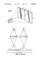
- FIG. 2is a schematic illustration of an optical projection system according to the prior art
- FIG. 3is a schematic illustration of an optical system according to the present invention.
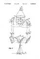
- FIG. 4is a schematic illustration of an optical system for displaying four discrete images in side-by-side relation according to another embodiment hereof.
- an optical systemincluding a projection system within a housing 10 for projecting images on a view screen 12.
- a pair of images I1 and I2are projected on screen 12 in side-by-side relation one to the other.
- the juncture of the imagesis illustrated at J. While the images I1 and I2 are illustrated in side-by-side relation with the juncture J extending in a vertical direction, it will be appreciated that the images I1 and I2 may be superposed one over the other with the juncture between the images extending in a horizontal direction. Other orientations of the images I1 and I2 are possible.
- the projection system 10forms the images I1 and I2 such that the juncture J has minimal or no illuminance discontinuities. In this manner, the viewing eye will discern essentially a single image comprising the combined images I1 and I2 with high resolution with little or not illuminance disparity between the images along the juncture.
- each projection system of the illustrated prior art systemincludes a light source 14, a spherical mirror 16 for concentrating the light rays for direction through a condenser lens 18 and a second condenser lens 20.
- the light raysare directed through an image display 22 for projection of the image through a projection lens 24 for display on viewing screen 26.
- Each illustrated prior art projection systemis paired with another duplicate projection system such that the adjoining edge of the images projected thereby lie along a juncture on the view screen 26.
- an observer O1 directly in front of the viewing screen in line with the juncture of the two imagesobserves no illuminance disparity between the projected images.
- all other observers, for example, observer O2sees a substantial difference in the brightness and darkness of the edges of the images at their junction, hence, a substantial illuminance disparity. Accordingly, it is this disparity which the present invention substantially eliminates.
- the optical projection system hereofincludes a light source 30, a spherical mirror 32 for concentrating the light rays, and a condenser lens 34 for directing the light rays to the first lens 36 of paired afocal lenses 36 and 42.
- the light rays through the left-half of the first lens 36are directed against a first flat mirror 38, then a parallel second flat mirror 40 for directing the collimated light through a second lens 42 of the pair of afocal lenses.
- the light rays passing, for example, through one-half of the first lens 36are directed through one-half of the second lens 42.
- An image display 44is disposed along the optical path for receiving the light rays passing through the portions or segments of the paired afocal lens 36 and 42.
- the light rays passing through the segment of lens 42are focused by that lens for entry into the single projection lens 46.
- the light rays from the lens 42 passing through image display 44are directed by flat mirror 46 and 48 for entry through projection lens 46 in such manner that the inner margin of image display 44 lies along the optical axis A of projection lens 46, while the light rays passing through the outer margin of image display 44 are denoted by the letters OM.
- the opposite or right-hand portion of the optical system illustrated in FIG. 3is the mirror image of the left-hand portion described above.
- light rays from source 30pass through the other segment or portion of lens 36 for passage through a portion of a second lens 42' by means of flat mirrors 38' and 40'.
- the light rays passing through the segment of lens 42'also pass through discrete image display 44' and are focused for passing through the single projection lens 46.
- Mirrors 46' and 48'return the optical path to projection lens 46.
- the light rays passing through the inner margin of image display 44'lie along the optical axis A of the projection lens 46, while those passing through the outer margin of image display 44' are designated OM'.
- the outer margins of the image displays 44 and 44'lie along the juncture J on the view screen 26, but with minimal or no illuminance disparity at their juncture. That is, the images at their juncture blend with one another without discernible disparity in illuminance.
- FIG. 4there is illustrated an image projection system according to a further embodiment of the present invention wherein four discrete images are projected onto a viewing screen, with substantially no illuminance disparity at the adjoining edges of the images.
- the projecting system illustrated in FIG. 4includes a light source 50, a spherical mirror 52 for concentrating the light rays, and a condensor lens 54 for directing the light rays to the first lens 56.
- Lens 56directs light rays against the four flat mirrored surfaces 58, 60, 62 and 64 of an upright pyramidally-shaped structure 66 supporting the mirrored surfaces.
- the light raysare reflected from each of the mirrored surfaces 58, 60, 62 and 64 onto a mirror and lens system identical one to the other in each of the four quadrants. Only one of the mirror and lens system in a single quadrant will be described, it being appreciated that each of the other three mirror and lens systems in their associated quadrants is identical to the system to be described. Also, it will be appreciated that FIG. 4 illustrates two of the mirror and lens systems in opposite quadrants and that an additional pair of mirror and lens systems to be described lie in the other two quadrants opposite surfaces 60 and 64, respectively.
- the mirror and lens system in this embodimentinclude a first flat mirror 68 disposed parallel to the reflecting mirror 58 formed on the pyramid structure 66.
- the collimated light reflected from mirror 58 onto mirror 68is passed through a quadrant of a second lens 69 forming part of the paired afocal lens 56 and 69.
- the lens. 69may comprise a single-layer lens with the light from the four mirrored surfaces passing through associated quadrants of the single lens.
- An image display 72is disposed along the optical path for receiving the light rays passing through the portions or segments of the paired afocal lenses 56 and 69. The light rays passing through image display 72 are focussed for entry into a single projection lens 73.
- the light rays from lens 69pass through the image display 72 and are directed by the flat mirror 70 for reflection onto one of the mirrored surfaces 74 of a plurality of mirrored surfaces 74, 78, 80 and 82 formed on the surface of an inverted pyramidal structure 76.
- the pyramidal structure 76has mirrors arranged similarly as pyramidal structure 66, but downwardly directed.
- the light rays passing through image display 72are reflected by mirrors 70 and 74 and pass through the focussing lens 73 for display on a viewing screen 84.
- each of the four illustrated mirrored surfaces 68, 70, 68' and 70'represent the portions of the light useful for projecting the images onto the viewing screen 84.
- the image display 72is rotated in a plane parallel to the base of the pyramidal structure 66 45° to maximize the area of the surface useful for transmitting the light.
- the corners of the rectilinear image display 72are designated a, b, c and d and the light rays passing through those corners are traced on the drawing with corresponding designations.
- the rectilinear areas defined by the dotted lines on the pyramidal structure 66 and mirror 68represent the area of useful light transmitted through the image display 72.
- the actual image defined at a, b, c and dis projected onto mirrors 70 and 74 for projection through lens 73.
- the corresponding corners of the image of image display 72are also illustrated on the viewing screen by the letters a, b, c and d.
- the corresponding corners of the image of image display 70'are also illustrated on the viewing screen by the designations a', b', c' and d'.
- each of the four mirror and lens systemsprojects the image associated with each system onto the mirrored surfaces associated with the lower pyramid structure 76 for projection by projection lens 73 onto the viewing surface 84.
- the various images from the four quadrantsproject the images in a series of rectilinear images in side-by-side relation one to the other to form a single image with minimal illuminance discontinuities at their junctures.
Landscapes
- Physics & Mathematics (AREA)
- General Physics & Mathematics (AREA)
- Engineering & Computer Science (AREA)
- Multimedia (AREA)
- Signal Processing (AREA)
- Optics & Photonics (AREA)
- Projection Apparatus (AREA)
- Transforming Electric Information Into Light Information (AREA)
- Stereoscopic And Panoramic Photography (AREA)
Abstract
Description
Claims (18)
Priority Applications (3)
| Application Number | Priority Date | Filing Date | Title |
|---|---|---|---|
| US07/785,921US5153621A (en) | 1991-10-31 | 1991-10-31 | Optical system for projecting multiple images in adjoining relation without illuminance discontinuities |
| EP92402696AEP0540380A1 (en) | 1991-10-31 | 1992-10-02 | Optical system for projecting multiple images in adjoining relation without illuminance discontinuities |
| JP4310887AJPH05215988A (en) | 1991-10-31 | 1992-10-26 | Optical apparatus for projecting a plu- rality of images adjacent to one another |
Applications Claiming Priority (1)
| Application Number | Priority Date | Filing Date | Title |
|---|---|---|---|
| US07/785,921US5153621A (en) | 1991-10-31 | 1991-10-31 | Optical system for projecting multiple images in adjoining relation without illuminance discontinuities |
Publications (1)
| Publication Number | Publication Date |
|---|---|
| US5153621Atrue US5153621A (en) | 1992-10-06 |
Family
ID=25137028
Family Applications (1)
| Application Number | Title | Priority Date | Filing Date |
|---|---|---|---|
| US07/785,921Expired - Fee RelatedUS5153621A (en) | 1991-10-31 | 1991-10-31 | Optical system for projecting multiple images in adjoining relation without illuminance discontinuities |
Country Status (3)
| Country | Link |
|---|---|
| US (1) | US5153621A (en) |
| EP (1) | EP0540380A1 (en) |
| JP (1) | JPH05215988A (en) |
Cited By (35)
| Publication number | Priority date | Publication date | Assignee | Title |
|---|---|---|---|---|
| EP0560125A1 (en)* | 1992-03-07 | 1993-09-15 | Eastman Kodak Company | Projector |
| US5272496A (en)* | 1991-08-06 | 1993-12-21 | Thomson-Csf | Image projector with optimized luminous efficiency |
| US5300966A (en)* | 1991-05-23 | 1994-04-05 | Nippon Telegraph And Telephone Corporation | Projector |
| US5539483A (en)* | 1995-06-30 | 1996-07-23 | At&T Corp. | Panoramic projection apparatus |
| US5548348A (en)* | 1993-12-10 | 1996-08-20 | Japan Aviation Electronics Industry Limited | Distributed projection type liquid crystal display device |
| US5574580A (en)* | 1993-10-01 | 1996-11-12 | Hughes Aircraft Company | LCD with integral light confinement having a pair of afocal lenslets positioned between liquid crystal cells and color polarizers |
| WO1997018461A1 (en)* | 1995-11-15 | 1997-05-22 | Thomas Huhn | Device, use thereof and method for the inspection and examination of container walls |
| US5684626A (en)* | 1994-10-25 | 1997-11-04 | Edge Scientific Instrument Company Llc | Center masking illumination system and method |
| US5823662A (en)* | 1994-08-25 | 1998-10-20 | Lightware, Inc. | High efficiency illumination system |
| US5926283A (en)* | 1997-07-12 | 1999-07-20 | Optical Insights, Llc | Multi-spectral two dimensional imaging spectrometer |
| US5982497A (en)* | 1998-07-09 | 1999-11-09 | Optical Insights, Llc | Multi-spectral two-dimensional imaging spectrometer |
| US6193375B1 (en)* | 1997-09-22 | 2001-02-27 | Minolta Co., Ltd. | Display device |
| US6247815B1 (en) | 1997-06-16 | 2001-06-19 | Metavision Corporation | Work desk with panoramic display |
| US6424437B1 (en)* | 2000-10-10 | 2002-07-23 | Digilens, Inc. | Projection display employing switchable holographic optical elements |
| US20030063226A1 (en)* | 2000-03-31 | 2003-04-03 | Gibbon Michael A. | Digital projection equipment and techniques |
| US20030156262A1 (en)* | 2000-07-03 | 2003-08-21 | Baker Kenneth T | Equipment and techniques for invisible seaming of multiple projection displays |
| US6856466B2 (en) | 2001-07-05 | 2005-02-15 | Science & Engineering Associates, Inc. | Multiple imaging system |
| US6919990B2 (en) | 2000-04-18 | 2005-07-19 | Imax Corporation | Methods and systems for low loss separation and combination of light |
| US20060007406A1 (en)* | 2002-10-21 | 2006-01-12 | Sean Adkins | Equipment, systems and methods for control of color in projection displays |
| WO2005064932A3 (en)* | 2003-12-22 | 2007-02-01 | Thomson Licensing | Vertically oriented segmented display system |
| US20080092877A1 (en)* | 2006-09-14 | 2008-04-24 | James Mathew Monsebroten | Solar concentrator system |
| US20080259223A1 (en)* | 2004-07-08 | 2008-10-23 | Steven Charles Read | Equipment and Methods for the Display of High Resolution Images Using Multiple Projection Displays |
| US20090225433A1 (en)* | 2008-03-05 | 2009-09-10 | Contrast Optical Design & Engineering, Inc. | Multiple image camera and lens system |
| US20090244717A1 (en)* | 2008-03-28 | 2009-10-01 | Contrast Optical Design & Engineering, Inc. | Whole beam image splitting system |
| US7604354B1 (en)* | 2006-05-10 | 2009-10-20 | Ligon Thomas R | Three-dimensional projection apparatus using coaxial optical alignment |
| US20100128228A1 (en)* | 2008-11-26 | 2010-05-27 | Seiko Epson Corporation | Projector and projector system |
| US20100328780A1 (en)* | 2008-03-28 | 2010-12-30 | Contrast Optical Design And Engineering, Inc. | Whole Beam Image Splitting System |
| CN102193195A (en)* | 2010-03-04 | 2011-09-21 | 巴西赫尔穆特毛尔有限公司 | Apparatus for obscuring non-displaying areas of display panels |
| US9948829B2 (en) | 2016-02-12 | 2018-04-17 | Contrast, Inc. | Color matching across multiple sensors in an optical system |
| US20180356216A1 (en)* | 2016-02-23 | 2018-12-13 | Boe Technology Group Co., Ltd. | Distance measuring module, three-dimensional (3d) scanning system and distance measuring method |
| US10264196B2 (en) | 2016-02-12 | 2019-04-16 | Contrast, Inc. | Systems and methods for HDR video capture with a mobile device |
| US10554901B2 (en) | 2016-08-09 | 2020-02-04 | Contrast Inc. | Real-time HDR video for vehicle control |
| US10951888B2 (en) | 2018-06-04 | 2021-03-16 | Contrast, Inc. | Compressed high dynamic range video |
| US11265530B2 (en) | 2017-07-10 | 2022-03-01 | Contrast, Inc. | Stereoscopic camera |
| US12309427B2 (en) | 2018-08-14 | 2025-05-20 | Contrast, Inc. | Image compression |
Families Citing this family (4)
| Publication number | Priority date | Publication date | Assignee | Title |
|---|---|---|---|---|
| US5917926A (en)* | 1996-03-01 | 1999-06-29 | Durand-Wayland, Inc. | Optical inspection apparatus and method for articles such as fruit and the like |
| ES2123456B1 (en)* | 1997-03-21 | 1999-09-16 | Gonzalez Manzanares Jesus Mari | ELECTRONIC PROJECTION CINEMA VIA SATELLITE. |
| FR2765761B1 (en)* | 1997-07-07 | 1999-09-17 | Rs Automation Romeuf Sauze Aut | DEVICE AND METHOD FOR PROJECTING DIGITAL HIGH-RESOLUTION COLOR IMAGES ON A HEMISPHERIC SCREEN |
| FR2836727B1 (en)* | 2002-03-04 | 2006-02-24 | Vincent Lauer | CONFOCAL OPTICAL SCANNING DEVICE |
Citations (15)
| Publication number | Priority date | Publication date | Assignee | Title |
|---|---|---|---|---|
| US3248999A (en)* | 1961-04-10 | 1966-05-03 | Colorvision Inc | Compact wide angle projection system for projecting a multiplicity of separate images |
| US3440956A (en)* | 1967-06-26 | 1969-04-29 | Doban Labs Inc | Apparatus for sequentially printing and projecting data such as game scores |
| US3994351A (en)* | 1975-01-02 | 1976-11-30 | Velasco Scale Company, Inc. | Scale controller |
| US4084894A (en)* | 1973-03-24 | 1978-04-18 | Fuji Xerox Co., Ltd. | Array of optical projection devices |
| US4114037A (en)* | 1977-05-16 | 1978-09-12 | Northern Telecom Limited | Multiple lens system for an optical imaging device |
| US4150396A (en)* | 1974-09-06 | 1979-04-17 | Thomson-Csf | Erasable thermo-optic storage display of a transmitted color image |
| US4187011A (en)* | 1975-08-27 | 1980-02-05 | Solid Photography Inc. | Arrangement for applying coded illuminated patterns to an object |
| US4458993A (en)* | 1981-10-05 | 1984-07-10 | Kempf Paul S | Fingerprint comparator |
| US4552441A (en)* | 1984-06-29 | 1985-11-12 | International Business Machines Corporation | Color display from a single light valve |
| US4737843A (en)* | 1984-04-09 | 1988-04-12 | Raytheon Company | Color image display system for producing and combining four color component images each inverted in at least one aspect relative to the other images |
| US4763993A (en)* | 1987-04-30 | 1988-08-16 | N-View Corporation | Liquid crystal display for projection systems |
| US4917465A (en)* | 1989-03-28 | 1990-04-17 | In Focus Systems, Inc. | Color display system |
| US4944578A (en)* | 1988-07-21 | 1990-07-31 | Telex Communications | Color graphic imager utilizing a liquid crystal display |
| US4952925A (en)* | 1988-01-25 | 1990-08-28 | Bernd Haastert | Projectable passive liquid-crystal flat screen information centers |
| US5046837A (en)* | 1988-05-26 | 1991-09-10 | U.S. Philips Corporation | Illumination system |
Family Cites Families (4)
| Publication number | Priority date | Publication date | Assignee | Title |
|---|---|---|---|---|
| US3462215A (en)* | 1967-08-25 | 1969-08-19 | Rca Corp | Slide projector including two light paths and one slide magazine |
| JPS6488531A (en)* | 1987-09-30 | 1989-04-03 | Hitachi Ltd | Back surface projection type device |
| US4916485A (en)* | 1989-07-18 | 1990-04-10 | Parallex Company, Inc. | Xenon optical system for cinematograph projection |
| JP3158484B2 (en)* | 1991-05-23 | 2001-04-23 | 日本電信電話株式会社 | Projection display device |
- 1991
- 1991-10-31USUS07/785,921patent/US5153621A/ennot_activeExpired - Fee Related
- 1992
- 1992-10-02EPEP92402696Apatent/EP0540380A1/ennot_activeWithdrawn
- 1992-10-26JPJP4310887Apatent/JPH05215988A/enactivePending
Patent Citations (15)
| Publication number | Priority date | Publication date | Assignee | Title |
|---|---|---|---|---|
| US3248999A (en)* | 1961-04-10 | 1966-05-03 | Colorvision Inc | Compact wide angle projection system for projecting a multiplicity of separate images |
| US3440956A (en)* | 1967-06-26 | 1969-04-29 | Doban Labs Inc | Apparatus for sequentially printing and projecting data such as game scores |
| US4084894A (en)* | 1973-03-24 | 1978-04-18 | Fuji Xerox Co., Ltd. | Array of optical projection devices |
| US4150396A (en)* | 1974-09-06 | 1979-04-17 | Thomson-Csf | Erasable thermo-optic storage display of a transmitted color image |
| US3994351A (en)* | 1975-01-02 | 1976-11-30 | Velasco Scale Company, Inc. | Scale controller |
| US4187011A (en)* | 1975-08-27 | 1980-02-05 | Solid Photography Inc. | Arrangement for applying coded illuminated patterns to an object |
| US4114037A (en)* | 1977-05-16 | 1978-09-12 | Northern Telecom Limited | Multiple lens system for an optical imaging device |
| US4458993A (en)* | 1981-10-05 | 1984-07-10 | Kempf Paul S | Fingerprint comparator |
| US4737843A (en)* | 1984-04-09 | 1988-04-12 | Raytheon Company | Color image display system for producing and combining four color component images each inverted in at least one aspect relative to the other images |
| US4552441A (en)* | 1984-06-29 | 1985-11-12 | International Business Machines Corporation | Color display from a single light valve |
| US4763993A (en)* | 1987-04-30 | 1988-08-16 | N-View Corporation | Liquid crystal display for projection systems |
| US4952925A (en)* | 1988-01-25 | 1990-08-28 | Bernd Haastert | Projectable passive liquid-crystal flat screen information centers |
| US5046837A (en)* | 1988-05-26 | 1991-09-10 | U.S. Philips Corporation | Illumination system |
| US4944578A (en)* | 1988-07-21 | 1990-07-31 | Telex Communications | Color graphic imager utilizing a liquid crystal display |
| US4917465A (en)* | 1989-03-28 | 1990-04-17 | In Focus Systems, Inc. | Color display system |
Cited By (59)
| Publication number | Priority date | Publication date | Assignee | Title |
|---|---|---|---|---|
| US5300966A (en)* | 1991-05-23 | 1994-04-05 | Nippon Telegraph And Telephone Corporation | Projector |
| US5272496A (en)* | 1991-08-06 | 1993-12-21 | Thomson-Csf | Image projector with optimized luminous efficiency |
| EP0560125A1 (en)* | 1992-03-07 | 1993-09-15 | Eastman Kodak Company | Projector |
| US5574580A (en)* | 1993-10-01 | 1996-11-12 | Hughes Aircraft Company | LCD with integral light confinement having a pair of afocal lenslets positioned between liquid crystal cells and color polarizers |
| US5548348A (en)* | 1993-12-10 | 1996-08-20 | Japan Aviation Electronics Industry Limited | Distributed projection type liquid crystal display device |
| US5823662A (en)* | 1994-08-25 | 1998-10-20 | Lightware, Inc. | High efficiency illumination system |
| US5684626A (en)* | 1994-10-25 | 1997-11-04 | Edge Scientific Instrument Company Llc | Center masking illumination system and method |
| US5539483A (en)* | 1995-06-30 | 1996-07-23 | At&T Corp. | Panoramic projection apparatus |
| WO1997018461A1 (en)* | 1995-11-15 | 1997-05-22 | Thomas Huhn | Device, use thereof and method for the inspection and examination of container walls |
| US6247815B1 (en) | 1997-06-16 | 2001-06-19 | Metavision Corporation | Work desk with panoramic display |
| US5926283A (en)* | 1997-07-12 | 1999-07-20 | Optical Insights, Llc | Multi-spectral two dimensional imaging spectrometer |
| US6193375B1 (en)* | 1997-09-22 | 2001-02-27 | Minolta Co., Ltd. | Display device |
| US5982497A (en)* | 1998-07-09 | 1999-11-09 | Optical Insights, Llc | Multi-spectral two-dimensional imaging spectrometer |
| US20030063226A1 (en)* | 2000-03-31 | 2003-04-03 | Gibbon Michael A. | Digital projection equipment and techniques |
| US7224411B2 (en) | 2000-03-31 | 2007-05-29 | Imax Corporation | Digital projection equipment and techniques |
| EP2209044A1 (en)* | 2000-03-31 | 2010-07-21 | Imax Corporation | Digital Projection Equipment and Techniques |
| US6919990B2 (en) | 2000-04-18 | 2005-07-19 | Imax Corporation | Methods and systems for low loss separation and combination of light |
| US20030156262A1 (en)* | 2000-07-03 | 2003-08-21 | Baker Kenneth T | Equipment and techniques for invisible seaming of multiple projection displays |
| US7193654B2 (en) | 2000-07-03 | 2007-03-20 | Imax Corporation | Equipment and techniques for invisible seaming of multiple projection displays |
| US6424437B1 (en)* | 2000-10-10 | 2002-07-23 | Digilens, Inc. | Projection display employing switchable holographic optical elements |
| US6856466B2 (en) | 2001-07-05 | 2005-02-15 | Science & Engineering Associates, Inc. | Multiple imaging system |
| US20060007406A1 (en)* | 2002-10-21 | 2006-01-12 | Sean Adkins | Equipment, systems and methods for control of color in projection displays |
| WO2005064932A3 (en)* | 2003-12-22 | 2007-02-01 | Thomson Licensing | Vertically oriented segmented display system |
| US8251512B2 (en) | 2004-07-08 | 2012-08-28 | Imax Corporation | Equipment and methods for the display of high resolution images using multiple projection displays |
| US20080259223A1 (en)* | 2004-07-08 | 2008-10-23 | Steven Charles Read | Equipment and Methods for the Display of High Resolution Images Using Multiple Projection Displays |
| US7604354B1 (en)* | 2006-05-10 | 2009-10-20 | Ligon Thomas R | Three-dimensional projection apparatus using coaxial optical alignment |
| US8689784B2 (en)* | 2006-09-14 | 2014-04-08 | James Matthew Monsebroten | Solar concentrator system |
| US20080092877A1 (en)* | 2006-09-14 | 2008-04-24 | James Mathew Monsebroten | Solar concentrator system |
| US7961398B2 (en) | 2008-03-05 | 2011-06-14 | Contrast Optical Design & Engineering, Inc. | Multiple image camera and lens system |
| US20090225433A1 (en)* | 2008-03-05 | 2009-09-10 | Contrast Optical Design & Engineering, Inc. | Multiple image camera and lens system |
| US20100328780A1 (en)* | 2008-03-28 | 2010-12-30 | Contrast Optical Design And Engineering, Inc. | Whole Beam Image Splitting System |
| US8320047B2 (en) | 2008-03-28 | 2012-11-27 | Contrast Optical Design & Engineering, Inc. | Whole beam image splitting system |
| US8441732B2 (en) | 2008-03-28 | 2013-05-14 | Michael D. Tocci | Whole beam image splitting system |
| US8619368B2 (en) | 2008-03-28 | 2013-12-31 | Contrast Optical Design & Engineering, Inc. | Whole beam image splitting system |
| US20090244717A1 (en)* | 2008-03-28 | 2009-10-01 | Contrast Optical Design & Engineering, Inc. | Whole beam image splitting system |
| US20100128228A1 (en)* | 2008-11-26 | 2010-05-27 | Seiko Epson Corporation | Projector and projector system |
| US8439508B2 (en)* | 2008-11-26 | 2013-05-14 | Seiko Epson Corporation | Projector and projector system |
| CN102193195A (en)* | 2010-03-04 | 2011-09-21 | 巴西赫尔穆特毛尔有限公司 | Apparatus for obscuring non-displaying areas of display panels |
| US11463605B2 (en) | 2016-02-12 | 2022-10-04 | Contrast, Inc. | Devices and methods for high dynamic range video |
| US11785170B2 (en) | 2016-02-12 | 2023-10-10 | Contrast, Inc. | Combined HDR/LDR video streaming |
| US10200569B2 (en) | 2016-02-12 | 2019-02-05 | Contrast, Inc. | Color matching across multiple sensors in an optical system |
| US10257393B2 (en) | 2016-02-12 | 2019-04-09 | Contrast, Inc. | Devices and methods for high dynamic range video |
| US10257394B2 (en) | 2016-02-12 | 2019-04-09 | Contrast, Inc. | Combined HDR/LDR video streaming |
| US10264196B2 (en) | 2016-02-12 | 2019-04-16 | Contrast, Inc. | Systems and methods for HDR video capture with a mobile device |
| US10536612B2 (en) | 2016-02-12 | 2020-01-14 | Contrast, Inc. | Color matching across multiple sensors in an optical system |
| US12250357B2 (en) | 2016-02-12 | 2025-03-11 | Contrast, Inc. | Combined HDR/LDR video streaming |
| US10742847B2 (en) | 2016-02-12 | 2020-08-11 | Contrast, Inc. | Devices and methods for high dynamic range video |
| US10805505B2 (en) | 2016-02-12 | 2020-10-13 | Contrast, Inc. | Combined HDR/LDR video streaming |
| US10819925B2 (en) | 2016-02-12 | 2020-10-27 | Contrast, Inc. | Devices and methods for high dynamic range imaging with co-planar sensors |
| US11637974B2 (en) | 2016-02-12 | 2023-04-25 | Contrast, Inc. | Systems and methods for HDR video capture with a mobile device |
| US9948829B2 (en) | 2016-02-12 | 2018-04-17 | Contrast, Inc. | Color matching across multiple sensors in an optical system |
| US11368604B2 (en) | 2016-02-12 | 2022-06-21 | Contrast, Inc. | Combined HDR/LDR video streaming |
| US20180356216A1 (en)* | 2016-02-23 | 2018-12-13 | Boe Technology Group Co., Ltd. | Distance measuring module, three-dimensional (3d) scanning system and distance measuring method |
| US11910099B2 (en) | 2016-08-09 | 2024-02-20 | Contrast, Inc. | Real-time HDR video for vehicle control |
| US10554901B2 (en) | 2016-08-09 | 2020-02-04 | Contrast Inc. | Real-time HDR video for vehicle control |
| US11265530B2 (en) | 2017-07-10 | 2022-03-01 | Contrast, Inc. | Stereoscopic camera |
| US10951888B2 (en) | 2018-06-04 | 2021-03-16 | Contrast, Inc. | Compressed high dynamic range video |
| US11985316B2 (en) | 2018-06-04 | 2024-05-14 | Contrast, Inc. | Compressed high dynamic range video |
| US12309427B2 (en) | 2018-08-14 | 2025-05-20 | Contrast, Inc. | Image compression |
Also Published As
| Publication number | Publication date |
|---|---|
| EP0540380A1 (en) | 1993-05-05 |
| JPH05215988A (en) | 1993-08-27 |
Similar Documents
| Publication | Publication Date | Title |
|---|---|---|
| US5153621A (en) | Optical system for projecting multiple images in adjoining relation without illuminance discontinuities | |
| US5808589A (en) | Optical system for a head mounted display combining high and low resolution images | |
| US5253116A (en) | Collimated viewing device with off-axis spherical mirror for simulator | |
| US4736214A (en) | Apparatus and method for producing three-dimensional images from two-dimensional sources | |
| US5191472A (en) | Apparatus having a screen with light blocking elements | |
| US4345817A (en) | Wide angle display device | |
| US4427274A (en) | Wide angle projection system | |
| US20190049640A1 (en) | Transmissive aerial image display | |
| US3932702A (en) | Optical system for the display of visual images | |
| JPH03213840A (en) | Rear projection type screen and rear projection type image display device using it | |
| US4918535A (en) | Television projection system | |
| US6421182B1 (en) | Apparatus for displaying an image suspended in space | |
| US3944351A (en) | Apparatus for superimposing a plurality of images | |
| JPS6193424A (en) | Light projector | |
| US6204973B1 (en) | Apparatus for displaying an image suspended in space | |
| US4112462A (en) | Infinity image display having increased vertical field of view | |
| JPS62194788A (en) | Projector | |
| JPH07218893A (en) | Distributed projection type liquid crystal display device | |
| RU2090979C1 (en) | Three-dimensional image reproducing device | |
| US4237493A (en) | Television support and picture projector | |
| US12219295B2 (en) | Display device | |
| JPH0588264A (en) | Rear projection type display device | |
| JPH03132738A (en) | Backprojection type display device | |
| JPS60227238A (en) | Video projector system | |
| JPS63231433A (en) | Transparent screen |
Legal Events
| Date | Code | Title | Description |
|---|---|---|---|
| AS | Assignment | Owner name:NVIEW CORPORATION, VIRGINIA Free format text:ASSIGNMENT OF ASSIGNORS INTEREST.;ASSIGNOR:VOGELEY, ARTHUR W.;REEL/FRAME:005901/0876 Effective date:19911029 | |
| AS | Assignment | Owner name:SIGNET BANK, VIRGINIA Free format text:SECURITY INTEREST;ASSIGNOR:NVIEW CORPORATION;REEL/FRAME:007803/0584 Effective date:19960206 | |
| FPAY | Fee payment | Year of fee payment:4 | |
| AS | Assignment | Owner name:CIT GROUP,THE/CREDIT FINANCE, INC, ILLINOIS Free format text:SECURITY INTEREST;ASSIGNOR:NVIEW CORPORATION;REEL/FRAME:008989/0014 Effective date:19980223 | |
| AS | Assignment | Owner name:NVIEW CORPORATION, VIRGINIA Free format text:RELEASE OF SECURITY INTEREST;ASSIGNOR:FIRST UNION NATIONAL BANK (FORMERLY SIGNET BANK);REEL/FRAME:009064/0231 Effective date:19980223 | |
| REMI | Maintenance fee reminder mailed | ||
| LAPS | Lapse for failure to pay maintenance fees | ||
| FP | Expired due to failure to pay maintenance fee | Effective date:20001006 | |
| STCH | Information on status: patent discontinuation | Free format text:PATENT EXPIRED DUE TO NONPAYMENT OF MAINTENANCE FEES UNDER 37 CFR 1.362 |