US5153525A - Vehicle detector with series resonant oscillator drive - Google Patents
Vehicle detector with series resonant oscillator driveDownload PDFInfo
- Publication number
- US5153525A US5153525AUS07/716,010US71601091AUS5153525AUS 5153525 AUS5153525 AUS 5153525AUS 71601091 AUS71601091 AUS 71601091AUS 5153525 AUS5153525 AUS 5153525A
- Authority
- US
- United States
- Prior art keywords
- oscillator
- signal
- circuit
- current
- function
- Prior art date
- Legal status (The legal status is an assumption and is not a legal conclusion. Google has not performed a legal analysis and makes no representation as to the accuracy of the status listed.)
- Expired - Lifetime
Links
Images


Classifications
- G—PHYSICS
- G08—SIGNALLING
- G08G—TRAFFIC CONTROL SYSTEMS
- G08G1/00—Traffic control systems for road vehicles
- G08G1/01—Detecting movement of traffic to be counted or controlled
- G08G1/042—Detecting movement of traffic to be counted or controlled using inductive or magnetic detectors
Definitions
- the present inventionrelates to an oscillator used to drive an inductive sensor.
- the present inventionrelates to detection systems such as a vehicle detector which use inductive sensors.
- Inductive sensorsare used for a wide variety of detection systems.
- inductive sensorsare used in systems which detect the presence of conductive or ferromagnetic articles within a specified area.
- Vehicle detectorsare a common type of detection systems in which inductive sensors are used.
- Vehicle detectorsare used in traffic control systems to provide input data required by a controller to control signal lights. Vehicle detectors are connected to one or more inductive sensors and operate on the principle of an inductance change caused by the movement of a vehicle in the vicinity of the inductive sensor.
- the inductive sensorcan take a number of different forms, but commonly is a wire loop which is buried in the roadway and which acts as an inductor.
- the vehicle detectorgenerally includes circuitry which operates in conjunction with the inductive sensor to measure changes in inductance and to provide output signals as a function of those inductance changes.
- the vehicle detectorincludes an oscillator circuit which produces an oscillator output signal having a frequency which is dependent on sensor inductance.
- the sensor inductanceis in turn dependent on whether the inductive sensor is loaded by the presence of a vehicle.
- the sensoris driven as a part of a resonant circuit of the oscillator.
- the vehicle detectormeasures changes in inductance in the sensor by monitoring the frequency of the oscillator output signal.
- vehicle detectorsare shown, for example, in U.S. Pat. No. 3,943,339 (Koerner et al.) and in U.S. Pat. No. 3,989,932 (Koerner).
- the inductive sensors connected to a vehicle detectorcan have a nominal inductance which varies significantly.
- the inductive sensorscan be located at varying distances from the vehicle detector, which results in variation in the sensor resistance and inductance contributed by the lead-in cables which connect the sensor to the vehicle detector.
- the current supplied to the inductive sensorbe sinusoidal with minimal distortion.
- the presence of distortioncan affect the accuracy of the oscillator frequency measurements, which are based on the fundamental frequency of the oscillator signal.
- the prior art sensor drive oscillatorshave been capable of providing sine-wave oscillation for some load ranges, but they are not capable of providing sinewave oscillation over the range of loads described above. Increased distortion leads to increased instability in the ability to discern the fundamental frequency of the oscillator.
- the inductive sensoris driven with a constant voltage.
- An improved sensor drive oscillatorwhich is capable of providing sine-wave oscillation over a wide range of inductive loads, which can be started and stopped quickly, and which provides consistent drive current for a number of different sensor configurations with different inductances and losses would be highly desirable.
- the present inventionis a series resonant oscillator circuit to drive an inductive load (which includes an inductive sensor), and a detection system which uses the series resonant oscillator circuit and inductive sensor.
- the series resonant oscillator circuithas the inductive load connected in the series path with a capacitive impedance.
- An oscillator signal which provides power to the series pathis controlled as a function of current sensed in the series path.
- the frequency of the oscillator signalchanges as a function of changes in inductance of the inductive sensor.
- the series resonant oscillator circuitincludes a feedback circuit for deriving positive and negative feedback signals from a current sensor and supplying those feedback signals to an amplifier which produces the oscillator signal.
- the oscillator circuitpreferably includes means for changing relative levels of positive and negative feedback during each half cycle of the oscillator signal.
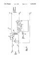
- FIG. 1is a block diagram of a vehicle detector which makes use of the series resonant oscillator circuit of the present invention.
- FIG. 2is an electrical schematic diagram of an input circuit for use in the vehicle detector of FIG. 1.
- FIG. 3is an electrical schematic diagram of a preferred embodiment of the series resonant oscillator of the present invention for use in the vehicle detector of FIG. 1.
- FIG. 4is an electrical schematic diagram of another embodiment of the series resonant oscillator of the present invention.
- Vehicle detector 10 shown in FIG. 1is a four channel system which monitors the inductance of inductive sensors 12A, 12B, 12C and 12D.
- Each inductive sensor 12A-12Dis connected to an input circuit 14A-14D, respectively.
- Sensor drive oscillator 16is selectively connected through input circuits 14A-14D to one of the inductive sensors 12A-12D to provide a drive current to one of the inductive sensors 12A-12D.
- the particular inductive sensor 12A-12D which is connected to oscillator 16is based upon which input circuit 14A-14D receives a sensor select signal from digital processor 20.
- Sensor drive oscillator 16produces an oscillator signal having a frequency which is a function of the inductance of the inductive sensors 12A-12D to which it is connected.
- dummy sensor 12Eis provided and is connected to sensor drive oscillator 16 in response to a select signal from digital processor 20.
- Dummy sensor 12Ehas an inductance which is unaffected by vehicles, and therefore provides a basis for adjustment or correction of the values measured by inductive sensors 12A-12D.
- vehicle detector 10The overall operation of vehicle detector 10 is controlled by digital processor 20.
- Crystal oscillator 22provides a high frequency clock signal for operation of digital processor 20.
- Power supply 24provides the necessary voltage levels for operation of the digital and analog circuitry within the vehicle detector 10.
- Digital processor 20receives inputs from operator interface 26 (through multiplexer 28), and receives control inputs from control input circuits 30A-30D.
- control input circuits 30A-30Dreceive logic signals, and convert those logic signals into input signals for processor 20.
- Processor 20also receives a line frequency reference input signal from line frequency reference input circuit 32. This input signal aids processor 20 in compensating signals from inductive sensors 12A-12D for inductance fluctuations caused by nearby power lines.
- Cycle counter 34, crystal oscillator 36, period counter 38, and processor 20form detector circuitry for detecting the frequency of the oscillator signal.
- Counters 34 and 38may be discrete counters (as illustrated in FIG. 1) or may be fully or partially incorporated into processor 20.
- digital processor 20includes on-board read only memory (ROM) and random access memory (RAM) storage.
- non-volatile memory 40stores additional data such as operator selected settings which are accessible to processor 20 through multiplexer 28.
- Vehicle detector 10has four output channels, one for each of the four sensors 12A-12D.
- the first output channelwhich is associated with inductive sensor 12A, includes primary output circuit 42A and auxiliary output circuit 44A.
- primary output circuit 42B and auxiliary output circuit 44Bare associated with inductive sensor 12B and form the second output channel.
- the third output channelincludes primary output circuit 42C and auxiliary output circuit 44C, which are associated with inductive sensor 12C.
- the fourth channelincludes primary output circuit 42D and auxiliary output circuit 44D, which are associated with inductive sensor 12D.
- Processor 20controls the operation of primary output circuits 42A-42D, and also controls the operation of auxiliary output circuits 44A-44D.
- the primary output circuits 42A-42Dprovide an output which is conductive even when vehicle detector 10 has a power failure.
- the auxiliary output circuits 44A-44Don the other hand, have outputs which are non-conductive when power to vehicle detector 10 is off.
- processor 20provides sensor select signals to input circuits 14A-14D to connect sensor drive oscillator 16 to inductive sensors 12A-12D in a time multiplexed fashion. Similarly, a sensor select signal to dummy sensor 12E causes it to be connected to sensor drive oscillator 16. Processor 20 also provides a control input to sensor drive oscillator 16 to select alternate capacitance values used to resonate with the inductive sensor 12A-12D or dummy sensor 12E. When processor 20 selects one of the input circuits 14A-14D or dummy sensor 12E, it also enables cycle counter 34. As sensor drive oscillator 16 is connected to an inductive load (e.g., input circuit 14A and sensor 12A) it begins to oscillate.
- an inductive loade.g., input circuit 14A and sensor 12A
- the oscillator signalis supplied to cycle counter 34, which counts oscillator cycles. After a brief stabilization period for the oscillator signal to stabilize, processor 20 enables period counter 38, which counts in response to a very high frequency (e.g., 20 MHz) signal from crystal oscillator 36.
- a very high frequencye.g. 20 MHz
- cycle counter 34When cycle counter 34 reaches the predetermined number (N seg ) of oscillator cycles after oscillator stabilization, it provides a control signal to period counter 38, which causes counter 38 to stop counting.
- the final count contained in period counter 38is a function of the frequency of the oscillator signal, and therefore the inductance of inductive sensor 12A.
- a change in the count which exceeds a predetermined thresholdindicates the presence of a vehicle near sensor 12A, and processor 20 provides the appropriate signals to primary and auxiliary output circuits 42A and 44A to signal the presence of a vehicle.
- FIG. 2is an electrical schematic diagram of input circuit 14A, which connects sensor 12A to sensor drive oscillator 16 in response to a sensor select signal from processor 20.
- Input circuit 14Ais representative of each of the input circuits 14A-14D of vehicle detector 10 of FIG. 1.
- Input circuit 14Ahas six terminals. Terminals 50 and 52 are connected to sensor drive oscillator 16, and terminals 54 and 56 are connected through a lead-in cable (not shown) to inductive sensor 12A. Terminal 58 receives the sensor select signal from processor 20, and terminal 60 is connected through a protection resistor (not shown) to ground.
- Input circuit 14Aincludes transformer 62, switch circuitry 64, resistors 66, 68 and 70, capacitor 72 and neon tube 74.
- Switch circuitry 64forms a FET-based switch connected in series with primary winding 62P of transformer 62 between terminals 50 and 52.
- Resistors 66, 68 and 70 and capacitor 72are connected with secondary winding 62S between terminals 54 and 56.
- Neon tube 74is connected in parallel with the combination of resistor 70, capacitor 72 and secondary winding 62S to provide transient protection.
- Switch 64includes FETs 76 and 78, diodes 80 and 82 (which are integral parts of FETs 76 and 78), and resistor 84.
- Oscillator 16is operably connected to sensor 12A when FETs 76 and 78 are turned on, and is disconnected from sensor 12A when FETs 76 and 78 are turned off.
- the inductive loadis primarily an inductive impedance, it does include resistive and capacitive components as well.
- FIG. 3shows a preferred embodiment of sensor drive oscillator circuit 16 of the present invention.
- Oscillator circuit 16is a series resonant oscillator which produces an oscillator signal at output terminal 90 which is a function of the inductance of inductive load connected to input terminals 100 and 102.
- the inductive loadcan be any one of input circuits 14A-14D (with associated inductive sensor 12A-12D) or dummy sensor 12E.
- Sensor drive oscillator circuit 16includes a twostage amplifier circuit (formed by amplifiers 104 and 106 and resistors 108 and 110); a series resonant circuit (formed by capacitors 112 and 114, switch 116, the inductive load, equivalent resistance R eq , and current sensing resistance 118); a positive feedback circuit (formed by resistors 120 and 122, potentiometer 124, and diodes 126 and 128); and a negative feedback circuit (formed by resistor 130, potentiometer 132, and capacitor 134).
- the output of second stage amplifier 106is connected to output terminal 90 to provide the oscillator signal.
- the output of amplifier 106is also connected to a series resonant path which includes equivalent resistance R eq , capacitor 112, the inductive load and current sensing resistor 118. If switch 116 is closed as a result of a control signal supplied by processor 20, capacitor 114 is connected in parallel with capacitor 112.
- the resonant frequency of this series resonant current path between output terminal 90 and groundis determined by the capacitance of either capacitor 112 by itself or the parallel combination of capacitors 112 and 114 (if switch 116 is closed), the inductance of the inductive load, and the total resistance of the series path.
- resistor R eqis shown in FIG. 3 to represent the equivalent resistance of all elements other than current sense resistor 118.
- the only variableis the inductance of the inductive sensor 12A-12D, which will be affected by the presence of metal in a passing vehicle.
- First stage amplifier 104has a positive (+) input terminal 140 and a negative (-) input terminal 142.
- a first (positive) feedback signalis supplied to + terminal 140 by the positive feedback circuit which includes resistors 120 and 122, potentiometer 124, and diodes 126 and 128.
- This positive feedback circuitis connected across current sensing resistor 118 and provides a signal which changes during each half cycle as a result of the action of diodes 126 and 128.
- diode 128will turn on, thus reducing the fraction of the signal across resistor 118 that appears at terminal 140 and thus also reducing the magnitude of the first feedback signal with respect to the magnitude of the second (negative) feedback signal.
- diode 126will turn on to reduce the magnitude of the first feedback signal with respect to the magnitude of the second feedback signal.
- the second (negative) feedback circuitis a voltage divider formed by resistor 130 and potentiometer 132 which is connected across resistor 118, and which is AC coupled through capacitor 134 to the - input terminal 142 of amplifier 104. Capacitor 134 and resistor 108 allow a stable DC operating point for amplifier 104.
- the voltage across resistor 118is primarily a function of current through the series resonant current path, and therefore the signal across current sensing resistor 118 is a function of the current which is being delivered to the inductive load (and thus to the inductive sensor 12A-12D).
- oscillator circuit 16The two feedback paths to first stage amplifier 104 allow oscillator 16 to start and stabilize very quickly, because loop gain is varied during each half cycle.
- oscillator circuit 16fully starts in less than two cycles of the resonant frequency.
- the positive feedback to + input terminal 140is initially greater than the negative feedback to - input terminal 142. This results in a gain which initially in every half cycle is significantly greater than one.
- the positive feedbackdecreases with respect to the negative feedback so that the gain is reduced to one or less as the peak of the half cycle is reached.
- Oscillator circuit 16provides a sine-wave drive to inductive sensors 12A-12D over a much wider range of load impedances than has been possible with the prior art parallel resonant loop oscillators.
- inductive sensors 12A-12Dare driven with constant AC currents regardless of the nominal inductance of the inductive load. As a result, consistent inductive sensor operation characteristics are assured, because the inductive sensor will be excited with the same current regardless of the type or length of lead-in cable used.
- Oscillationis virtually guaranteed for any inductive sensor load, R eq and L eq , as the gain, except for a small factor due to resistor 108, is independent of L eq and R eq .
- the oscillatorwill always start quickly, because the gain can be guaranteed to be significantly greater than one at zero or low sensor currents. This permits nearly all of the inductive sensor active time to be used as measurement time.
- first stage amplifier 104offers high input impedance at terminals 140 and 142 so that input impedance of amplifier 104 does not affect the two feedback circuits.
- Second stage amplifier 106exhibits an output impedance which does not vary as a function of instantaneous current from output terminal 90. The output impedance of amplifier 106, does partially determine the nominal frequency of the series resonant circuit, but it does not cause changes in the resonant frequency of the series resonant circuit that are significant when compared to those caused by vehicles e sensor 12A-12D.
- Table Iis a list of the components used in the preferred embodiment of oscillator 16 shown in FIG. 3.
- FIG. 4shows another embodiment of the series resonant oscillator of the present invention.
- Oscillator 200 of FIG. 4includes output terminal 202, input terminals 204 and 206, amplifier 208, a series resonant circuit (formed by capacitor 210, inductive load 212, and resistors 214 and 216), and a negative feedback circuit (formed by resistors 218, 220, 222 and diodes 224 and 226).
- Positive feedbackis provided to + input terminal 228 of amplifier 208 from the junction of a voltage divider formed by resistors 214 and 216.
- resistor 216acts as the current sensing resistor, since the current through inductive load 212 is equal to the voltage across resistor 216 divided by the resistance of resistor 216.
- Negative feedback in this embodimentis derived from output terminal 202, rather than from the current through the inductive load (as in oscillator 16 of FIG. 3).
- Resistors 218 and 220form a voltage divider which has its junction connected to - input terminal 224 of amplifier 208.
- a non-linear circuit formed by resistor 222 and diodes 224 and 226is connected in parallel with resistor 218. During each half cycle of the oscillator signal, the non-linear circuit causes a change in the relative amount of negative feedback with respect to positive feedback.
- oscillator 200features greater relative positive feedback at the beginning of each half cycle than at the peak.
- oscillator 200controls power delivered to a series resonant circuit as a function of current through inductive load 212. As a result, a constant AC current drive is achieved.
- the oscillator output signalhas a frequency which varies as a function of inductance of inductive load 212.
- Oscillator 16 of FIG. 3has been found to be preferable for use with inductive loads having inductive sensors and lead-in cables whose equivalent series resistance is not carefully controlled. In those applications in which smaller equivalent series resistance changes occur, oscillator 200 of FIG. 4 offers the advantage of simpler construction and fewer components.
- the series resonant oscillator of the present inventionprovides a stable drive to inductive sensors in a vehicle detector. Greater stability and consistent sensitivity over a wide range and wide variety of inductive loads is achieved.
Landscapes
- Physics & Mathematics (AREA)
- General Physics & Mathematics (AREA)
- Train Traffic Observation, Control, And Security (AREA)
- Traffic Control Systems (AREA)
- Measurement Of Resistance Or Impedance (AREA)
- Geophysics And Detection Of Objects (AREA)
Abstract
Description
TABLE I ______________________________________Amplifier 104AD 847JR Amplifier 106LH 0002CN Resistor 108 6.8Kohm Resistor 110 220ohm Capacitor 112 .047μF Capacitor 114 .047μF Switch 116 2N7002 (2)Resistor 118 33ohm Resistor 1201K ohm Resistor 12210K ohm Potentiometer 124 0-10K ohm Diode 1261N914 Diode 1281N914 Resistor 130 100ohm Potentiometer 132 0-2K ohm Capacitor 134 1.0 μF ______________________________________
Claims (21)
Priority Applications (5)
| Application Number | Priority Date | Filing Date | Title |
|---|---|---|---|
| US07/716,010US5153525A (en) | 1991-06-17 | 1991-06-17 | Vehicle detector with series resonant oscillator drive |
| CA002068896ACA2068896A1 (en) | 1991-06-17 | 1991-07-12 | Vehicle detector with series resonant oscillator drive |
| AU16337/92AAU662739B2 (en) | 1991-06-17 | 1992-05-15 | Vehicle detector with series resonant oscillator drive |
| EP92305451AEP0520661A1 (en) | 1991-06-17 | 1992-06-15 | Vehicle detector with series resonant oscillator drive |
| JP15683992AJPH05188155A (en) | 1991-06-17 | 1992-06-16 | Vehicle detection system |
Applications Claiming Priority (1)
| Application Number | Priority Date | Filing Date | Title |
|---|---|---|---|
| US07/716,010US5153525A (en) | 1991-06-17 | 1991-06-17 | Vehicle detector with series resonant oscillator drive |
Publications (1)
| Publication Number | Publication Date |
|---|---|
| US5153525Atrue US5153525A (en) | 1992-10-06 |
Family
ID=24876356
Family Applications (1)
| Application Number | Title | Priority Date | Filing Date |
|---|---|---|---|
| US07/716,010Expired - LifetimeUS5153525A (en) | 1991-06-17 | 1991-06-17 | Vehicle detector with series resonant oscillator drive |
Country Status (5)
| Country | Link |
|---|---|
| US (1) | US5153525A (en) |
| EP (1) | EP0520661A1 (en) |
| JP (1) | JPH05188155A (en) |
| AU (1) | AU662739B2 (en) |
| CA (1) | CA2068896A1 (en) |
Cited By (31)
| Publication number | Priority date | Publication date | Assignee | Title |
|---|---|---|---|---|
| US5278555A (en)* | 1991-06-17 | 1994-01-11 | Minnesota Mining And Manufacturing Company | Single inductive sensor vehicle detection and speed measurement |
| US5491475A (en)* | 1993-03-19 | 1996-02-13 | Honeywell Inc. | Magnetometer vehicle detector |
| US5523753A (en)* | 1994-09-12 | 1996-06-04 | Minnesota Mining And Manufacturing Company | Vehicle detector system with periodic source filtering |
| US5708427A (en)* | 1996-04-18 | 1998-01-13 | Bush; E. William | Vehicle in-lane positional indication/control by phase detection of RF signals induced in completely-passive resonant-loop circuits buried along a road lane |
| US5734338A (en)* | 1991-07-12 | 1998-03-31 | Minnesota Mining And Manufacturing Company | Vehicle detector with automatic sensitivity adjustment |
| US5751225A (en)* | 1994-09-12 | 1998-05-12 | Minnesota Mining And Manufacturing Company | Vehicle detector system with presence mode counting |
| US5936551A (en)* | 1997-04-03 | 1999-08-10 | Allen; Robert S. | Vehicle detector with improved reference tracking |
| US6087964A (en)* | 1997-04-24 | 2000-07-11 | Reno A & E | Vehicle detector with operational display |
| US6100821A (en)* | 1997-06-13 | 2000-08-08 | Matsushita Electric Industrial Co., Ltd. | Apparatus for detecting magnetostrictive resonator and traffic system |
| US6307385B1 (en) | 1997-12-30 | 2001-10-23 | Vibrosystm, Inc. | Capacitance measuring circuit for a capacitive sensor |
| US20020109609A1 (en)* | 1996-10-02 | 2002-08-15 | Innovapark Company L.L.C. | Electronic parking meter system |
| US6590400B2 (en) | 2001-06-29 | 2003-07-08 | Inductive Signature Technologies | Inductive signature measurement circuit |
| US20040032573A1 (en)* | 2000-11-30 | 2004-02-19 | Kia Silverbrook | Data projector with internal printer |
| US6803859B2 (en) | 2000-01-05 | 2004-10-12 | Inductive Signature Technologies, Inc. | Method and apparatus for active isolation in inductive loop detectors |
| US20080169385A1 (en)* | 2007-01-15 | 2008-07-17 | Ashraf Ahtasham | Vehicle detection system |
| US20100147832A1 (en)* | 2008-12-16 | 2010-06-17 | Barker Iii Charles R | Induction cookware identifying |
| US20110013022A1 (en)* | 2001-10-17 | 2011-01-20 | United Toll Systems, Inc. | Multilane vehicle information capture system |
| US7952021B2 (en) | 2007-05-03 | 2011-05-31 | United Toll Systems, Inc. | System and method for loop detector installation |
| US8135614B2 (en) | 2001-10-17 | 2012-03-13 | United Toll Systems, Inc. | Multiple RF read zone system |
| US8331621B1 (en)* | 2001-10-17 | 2012-12-11 | United Toll Systems, Inc. | Vehicle image capture system |
| US9026283B2 (en) | 2010-05-31 | 2015-05-05 | Central Signal, Llc | Train detection |
| WO2019118233A1 (en)* | 2017-12-13 | 2019-06-20 | Purdue Research Foundation | Nonlinear mass sensors based on electronic feedback |
| CN110308335A (en)* | 2019-07-08 | 2019-10-08 | 中国科学院合肥物质科学研究院 | Device, method and system for measuring resistance and inductance parameters of AC magnet coil |
| US10852451B2 (en)* | 2014-11-17 | 2020-12-01 | Stmicroelectronics S.R.L. | System for interfacing an LC sensor, related method and computer program product |
| US11055991B1 (en) | 2018-02-09 | 2021-07-06 | Applied Information, Inc. | Systems, methods, and devices for communication between traffic controller systems and mobile transmitters and receivers |
| US11205345B1 (en) | 2018-10-02 | 2021-12-21 | Applied Information, Inc. | Systems, methods, devices, and apparatuses for intelligent traffic signaling |
| US11922756B2 (en) | 2019-01-30 | 2024-03-05 | J.J. Mackay Canada Limited | Parking meter having touchscreen display |
| US11972654B2 (en) | 2015-08-11 | 2024-04-30 | J.J. Mackay Canada Limited | Lightweight vandal resistant parking meter |
| US12008856B2 (en) | 2011-03-03 | 2024-06-11 | J.J. Mackay Canada Limited | Single space parking meter and removable single space parking meter mechanism |
| US12368227B2 (en) | 2008-12-23 | 2025-07-22 | J.J. Mackay Canada Limited | Single space wireless parking with improved antenna placements |
| US12417669B2 (en) | 2015-08-08 | 2025-09-16 | J.J. Mackay Canada Limited | Lighweight vandal resistent parking meter |
Citations (18)
| Publication number | Priority date | Publication date | Assignee | Title |
|---|---|---|---|---|
| US3375493A (en)* | 1965-06-30 | 1968-03-26 | Gen Precision Systems Inc | Inductive loop presence detector |
| US3875555A (en)* | 1973-05-29 | 1975-04-01 | Indicator Controls Corp | Vehicle detection system |
| US3911389A (en)* | 1974-03-21 | 1975-10-07 | Us Transport | Magnetic gradient vehicle detector |
| US3943339A (en)* | 1974-04-29 | 1976-03-09 | Canoga Controls Corporation | Inductive loop detector system |
| US3989932A (en)* | 1974-02-21 | 1976-11-02 | Canoga Controls Corporation | Inductive loop vehicle detector |
| US4219740A (en)* | 1979-01-12 | 1980-08-26 | Eldec Corporation | Proximity sensing system and inductance measuring technique |
| US4333052A (en)* | 1977-06-14 | 1982-06-01 | Messer Griesheim Gmbh | Resonant circuit with two partial inductances |
| US4368428A (en)* | 1979-08-09 | 1983-01-11 | U.S. Philips Corporation | Method and arrangement for determining the velocity of a vehicle |
| US4430636A (en)* | 1981-06-29 | 1984-02-07 | Bruce Robert L | Loop detector for traffic signal control |
| US4449115A (en)* | 1980-10-15 | 1984-05-15 | Minnesota Mining And Manufacturing Company | Apparatus for detecting ferromagnetic material |
| US4459561A (en)* | 1980-11-14 | 1984-07-10 | Sarasota Automation Limited | Phase-lock loop controlled object detector oscillator |
| US4472706A (en)* | 1981-11-30 | 1984-09-18 | Hodge Patrick M | Vehicle presence loop detector |
| US4477772A (en)* | 1982-03-29 | 1984-10-16 | Canadian Patents & Development Limited | Frequency compensator for a current-comparator capacitance bridge |
| US4491841A (en)* | 1981-04-03 | 1985-01-01 | Sarasota Automation Limited | Self-adjusting inductive object-presence detector |
| US4668951A (en)* | 1982-08-13 | 1987-05-26 | Sarasota Automation Limited | Inductive loop vehicle detector |
| US4862162A (en)* | 1982-12-02 | 1989-08-29 | Sarasota Automation Limited | Environmental tracking in inductance loop vehicle detection systems |
| US4873494A (en)* | 1983-03-16 | 1989-10-10 | Sarasota Automation Limited | Inductive loop presence detector with cross talk filter |
| US4949054A (en)* | 1988-08-24 | 1990-08-14 | Setra Systems, Inc. | Temperature stable oscillator |
Family Cites Families (2)
| Publication number | Priority date | Publication date | Assignee | Title |
|---|---|---|---|---|
| US4500802A (en)* | 1982-06-21 | 1985-02-19 | Eaton Corporation | Three terminal bidirectional source to source FET circuit |
| DE3319431A1 (en)* | 1983-05-28 | 1984-11-29 | Robert Bosch Gmbh, 7000 Stuttgart | DETECTOR FOR DETECTING DATA OF A MOVING OBJECT AND METHOD FOR THE EVALUATION THEREOF |
- 1991
- 1991-06-17USUS07/716,010patent/US5153525A/ennot_activeExpired - Lifetime
- 1991-07-12CACA002068896Apatent/CA2068896A1/ennot_activeAbandoned
- 1992
- 1992-05-15AUAU16337/92Apatent/AU662739B2/ennot_activeCeased
- 1992-06-15EPEP92305451Apatent/EP0520661A1/ennot_activeWithdrawn
- 1992-06-16JPJP15683992Apatent/JPH05188155A/enactivePending
Patent Citations (18)
| Publication number | Priority date | Publication date | Assignee | Title |
|---|---|---|---|---|
| US3375493A (en)* | 1965-06-30 | 1968-03-26 | Gen Precision Systems Inc | Inductive loop presence detector |
| US3875555A (en)* | 1973-05-29 | 1975-04-01 | Indicator Controls Corp | Vehicle detection system |
| US3989932A (en)* | 1974-02-21 | 1976-11-02 | Canoga Controls Corporation | Inductive loop vehicle detector |
| US3911389A (en)* | 1974-03-21 | 1975-10-07 | Us Transport | Magnetic gradient vehicle detector |
| US3943339A (en)* | 1974-04-29 | 1976-03-09 | Canoga Controls Corporation | Inductive loop detector system |
| US4333052A (en)* | 1977-06-14 | 1982-06-01 | Messer Griesheim Gmbh | Resonant circuit with two partial inductances |
| US4219740A (en)* | 1979-01-12 | 1980-08-26 | Eldec Corporation | Proximity sensing system and inductance measuring technique |
| US4368428A (en)* | 1979-08-09 | 1983-01-11 | U.S. Philips Corporation | Method and arrangement for determining the velocity of a vehicle |
| US4449115A (en)* | 1980-10-15 | 1984-05-15 | Minnesota Mining And Manufacturing Company | Apparatus for detecting ferromagnetic material |
| US4459561A (en)* | 1980-11-14 | 1984-07-10 | Sarasota Automation Limited | Phase-lock loop controlled object detector oscillator |
| US4491841A (en)* | 1981-04-03 | 1985-01-01 | Sarasota Automation Limited | Self-adjusting inductive object-presence detector |
| US4430636A (en)* | 1981-06-29 | 1984-02-07 | Bruce Robert L | Loop detector for traffic signal control |
| US4472706A (en)* | 1981-11-30 | 1984-09-18 | Hodge Patrick M | Vehicle presence loop detector |
| US4477772A (en)* | 1982-03-29 | 1984-10-16 | Canadian Patents & Development Limited | Frequency compensator for a current-comparator capacitance bridge |
| US4668951A (en)* | 1982-08-13 | 1987-05-26 | Sarasota Automation Limited | Inductive loop vehicle detector |
| US4862162A (en)* | 1982-12-02 | 1989-08-29 | Sarasota Automation Limited | Environmental tracking in inductance loop vehicle detection systems |
| US4873494A (en)* | 1983-03-16 | 1989-10-10 | Sarasota Automation Limited | Inductive loop presence detector with cross talk filter |
| US4949054A (en)* | 1988-08-24 | 1990-08-14 | Setra Systems, Inc. | Temperature stable oscillator |
Cited By (49)
| Publication number | Priority date | Publication date | Assignee | Title |
|---|---|---|---|---|
| US5278555A (en)* | 1991-06-17 | 1994-01-11 | Minnesota Mining And Manufacturing Company | Single inductive sensor vehicle detection and speed measurement |
| US5734338A (en)* | 1991-07-12 | 1998-03-31 | Minnesota Mining And Manufacturing Company | Vehicle detector with automatic sensitivity adjustment |
| US5491475A (en)* | 1993-03-19 | 1996-02-13 | Honeywell Inc. | Magnetometer vehicle detector |
| US5523753A (en)* | 1994-09-12 | 1996-06-04 | Minnesota Mining And Manufacturing Company | Vehicle detector system with periodic source filtering |
| US5751225A (en)* | 1994-09-12 | 1998-05-12 | Minnesota Mining And Manufacturing Company | Vehicle detector system with presence mode counting |
| US5708427A (en)* | 1996-04-18 | 1998-01-13 | Bush; E. William | Vehicle in-lane positional indication/control by phase detection of RF signals induced in completely-passive resonant-loop circuits buried along a road lane |
| US20020109609A1 (en)* | 1996-10-02 | 2002-08-15 | Innovapark Company L.L.C. | Electronic parking meter system |
| US7014355B2 (en) | 1996-10-02 | 2006-03-21 | Innovapark Company Llc | Electronic parking meter system |
| US5936551A (en)* | 1997-04-03 | 1999-08-10 | Allen; Robert S. | Vehicle detector with improved reference tracking |
| US6087964A (en)* | 1997-04-24 | 2000-07-11 | Reno A & E | Vehicle detector with operational display |
| US6100821A (en)* | 1997-06-13 | 2000-08-08 | Matsushita Electric Industrial Co., Ltd. | Apparatus for detecting magnetostrictive resonator and traffic system |
| US6307385B1 (en) | 1997-12-30 | 2001-10-23 | Vibrosystm, Inc. | Capacitance measuring circuit for a capacitive sensor |
| US6803859B2 (en) | 2000-01-05 | 2004-10-12 | Inductive Signature Technologies, Inc. | Method and apparatus for active isolation in inductive loop detectors |
| US20040032573A1 (en)* | 2000-11-30 | 2004-02-19 | Kia Silverbrook | Data projector with internal printer |
| US6590400B2 (en) | 2001-06-29 | 2003-07-08 | Inductive Signature Technologies | Inductive signature measurement circuit |
| US20040095148A1 (en)* | 2001-06-29 | 2004-05-20 | Inductive Signature Technologies, Inc. | Inductive signature measurement circuit |
| US6911829B2 (en) | 2001-06-29 | 2005-06-28 | Inductive Signature Technologies, Inc. | Inductive signature measurement circuit |
| US8135614B2 (en) | 2001-10-17 | 2012-03-13 | United Toll Systems, Inc. | Multiple RF read zone system |
| US8331621B1 (en)* | 2001-10-17 | 2012-12-11 | United Toll Systems, Inc. | Vehicle image capture system |
| US20110013022A1 (en)* | 2001-10-17 | 2011-01-20 | United Toll Systems, Inc. | Multilane vehicle information capture system |
| US7925440B2 (en) | 2001-10-17 | 2011-04-12 | United Toll Systems, Inc. | Multilane vehicle information capture system |
| US8543285B2 (en) | 2001-10-17 | 2013-09-24 | United Toll Systems, Inc. | Multilane vehicle information capture system |
| US9067609B2 (en) | 2006-12-22 | 2015-06-30 | Central Signal, Llc | Vital solid state controller |
| US20080183306A1 (en)* | 2006-12-22 | 2008-07-31 | Central Signal, Llc | Vital solid state controller |
| US8028961B2 (en) | 2006-12-22 | 2011-10-04 | Central Signal, Llc | Vital solid state controller |
| US8469320B2 (en) | 2006-12-22 | 2013-06-25 | Central Signal, Llc | Vital solid state controller |
| US8888052B2 (en) | 2007-01-15 | 2014-11-18 | Central Signal, Llc | Vehicle detection system |
| US8157219B2 (en) | 2007-01-15 | 2012-04-17 | Central Signal, Llc | Vehicle detection system |
| US8517316B2 (en) | 2007-01-15 | 2013-08-27 | Central Signal, Llc | Vehicle detection system |
| US20080169385A1 (en)* | 2007-01-15 | 2008-07-17 | Ashraf Ahtasham | Vehicle detection system |
| US8975516B2 (en) | 2007-05-03 | 2015-03-10 | Transcore, Lp | System and method for loop detector installation |
| US7952021B2 (en) | 2007-05-03 | 2011-05-31 | United Toll Systems, Inc. | System and method for loop detector installation |
| US20100147832A1 (en)* | 2008-12-16 | 2010-06-17 | Barker Iii Charles R | Induction cookware identifying |
| US12368227B2 (en) | 2008-12-23 | 2025-07-22 | J.J. Mackay Canada Limited | Single space wireless parking with improved antenna placements |
| US9026283B2 (en) | 2010-05-31 | 2015-05-05 | Central Signal, Llc | Train detection |
| US12430978B2 (en) | 2011-03-03 | 2025-09-30 | J.J. Mackay Canada Limited | Parking meter with contactless payment |
| US12008856B2 (en) | 2011-03-03 | 2024-06-11 | J.J. Mackay Canada Limited | Single space parking meter and removable single space parking meter mechanism |
| US10852451B2 (en)* | 2014-11-17 | 2020-12-01 | Stmicroelectronics S.R.L. | System for interfacing an LC sensor, related method and computer program product |
| US12417669B2 (en) | 2015-08-08 | 2025-09-16 | J.J. Mackay Canada Limited | Lighweight vandal resistent parking meter |
| US11972654B2 (en) | 2015-08-11 | 2024-04-30 | J.J. Mackay Canada Limited | Lightweight vandal resistant parking meter |
| US11978300B2 (en) | 2015-08-11 | 2024-05-07 | J.J. Mackay Canada Limited | Single space parking meter |
| WO2019118233A1 (en)* | 2017-12-13 | 2019-06-20 | Purdue Research Foundation | Nonlinear mass sensors based on electronic feedback |
| US11069234B1 (en) | 2018-02-09 | 2021-07-20 | Applied Information, Inc. | Systems, methods, and devices for communication between traffic controller systems and mobile transmitters and receivers |
| US11854389B1 (en) | 2018-02-09 | 2023-12-26 | Applied Information, Inc. | Systems, methods, and devices for communication between traffic controller systems and mobile transmitters and receivers |
| US11594127B1 (en) | 2018-02-09 | 2023-02-28 | Applied Information, Inc. | Systems, methods, and devices for communication between traffic controller systems and mobile transmitters and receivers |
| US11055991B1 (en) | 2018-02-09 | 2021-07-06 | Applied Information, Inc. | Systems, methods, and devices for communication between traffic controller systems and mobile transmitters and receivers |
| US11205345B1 (en) | 2018-10-02 | 2021-12-21 | Applied Information, Inc. | Systems, methods, devices, and apparatuses for intelligent traffic signaling |
| US11922756B2 (en) | 2019-01-30 | 2024-03-05 | J.J. Mackay Canada Limited | Parking meter having touchscreen display |
| CN110308335A (en)* | 2019-07-08 | 2019-10-08 | 中国科学院合肥物质科学研究院 | Device, method and system for measuring resistance and inductance parameters of AC magnet coil |
Also Published As
| Publication number | Publication date |
|---|---|
| AU1633792A (en) | 1992-12-24 |
| CA2068896A1 (en) | 1992-12-18 |
| JPH05188155A (en) | 1993-07-30 |
| AU662739B2 (en) | 1995-09-14 |
| EP0520661A1 (en) | 1992-12-30 |
Similar Documents
| Publication | Publication Date | Title |
|---|---|---|
| US5153525A (en) | Vehicle detector with series resonant oscillator drive | |
| US4068189A (en) | Linear oscillator for proximity sensor | |
| US5757196A (en) | Capacitive switch actuated by changes in a sensor capacitance | |
| EP0546735B1 (en) | Humidity meter | |
| JP3275099B2 (en) | Inductive linear displacement transducer and temperature compensated signal processor | |
| KR920004084B1 (en) | Coin Identification Device | |
| JPH0329415A (en) | Induction proximity switch | |
| US6031430A (en) | Temperature stabilized oscillator and proximity switch containing the oscillator | |
| US5361064A (en) | Vehicle detector with power main noise compensation | |
| US5504425A (en) | Inductive sensor responsive to the distance to a conductive or magnetizable object | |
| JP2954662B2 (en) | Method for compensating fluctuation of output signal of resonant circuit and distance detector | |
| KR20140052827A (en) | Impedance source ranging apparatus and method | |
| US5239209A (en) | Zero crossing detection circuit | |
| JPS5945106B2 (en) | Current sensing device particularly suitable for use as a ground leak detection device | |
| US5553479A (en) | Threshold level calibration method and apparatus | |
| JP2001203565A (en) | Proximity sensor | |
| US4992740A (en) | Apparatus which uses a simulated inductor in the measurement of an electrical parameter of a device under test | |
| JPH0257984A (en) | Circuit apparatus for application connected to inductive and capacitive device for non-destructive measurement of orm resistance of thin film | |
| USRE27829E (en) | Tiffanycapacitance-measuring technique | |
| US4742294A (en) | Helix current sense system | |
| US20030234654A1 (en) | Apparatus for calibrating high frequency signal measurement equipment | |
| JP3809635B2 (en) | Coil copper resistance compensation circuit | |
| US3518551A (en) | Circuit arrangement for measuring the damping of an oscillation | |
| JPH0311958Y2 (en) | ||
| JP3094246B2 (en) | Capacitance measurement method |
Legal Events
| Date | Code | Title | Description |
|---|---|---|---|
| AS | Assignment | Owner name:MINNESOTA MINING AND MANUFACTURING COMPANY A COR Free format text:ASSIGNMENT OF ASSIGNORS INTEREST.;ASSIGNORS:HOEKMAN, EARL B.;HAMER, STEVEN M.;REEL/FRAME:005749/0256 Effective date:19910617 | |
| STCF | Information on status: patent grant | Free format text:PATENTED CASE | |
| FPAY | Fee payment | Year of fee payment:4 | |
| FPAY | Fee payment | Year of fee payment:8 | |
| FEPP | Fee payment procedure | Free format text:PAYOR NUMBER ASSIGNED (ORIGINAL EVENT CODE: ASPN); ENTITY STATUS OF PATENT OWNER: LARGE ENTITY | |
| FPAY | Fee payment | Year of fee payment:12 | |
| AS | Assignment | Owner name:3M INNOVATIVE PROPERTIES COMPANY, MINNESOTA Free format text:ASSIGNMENT OF ASSIGNORS INTEREST;ASSIGNOR:3M COMPANY (FORMERLY MINNESOTA MINING AND MANUFACTURING COMPANY), A CORP. OF DELAWARE;REEL/FRAME:018989/0319 Effective date:20070301 | |
| AS | Assignment | Owner name:FREEPORT FINANCIAL LLC, AS AGENT, ILLINOIS Free format text:SECURITY AGREEMENT;ASSIGNOR:GLOBAL TRAFFIC TECHNOLOGIES, LLC;REEL/FRAME:019501/0730 Effective date:20070628 | |
| AS | Assignment | Owner name:GLOBAL TRAFFIC TECHNOLOGIES, LLC, MINNESOTA Free format text:ASSIGNMENT OF ASSIGNORS INTEREST;ASSIGNOR:3M INNOVATIVE PROPERTIES COMPANY;REEL/FRAME:019744/0210 Effective date:20070626 | |
| AS | Assignment | Owner name:TORQUEST MANAGEMENT SERVICES LIMITED PARTNERSHIP, Free format text:SECURITY AGREEMENT;ASSIGNOR:GLOBAL TRAFFIC TECHNOLOGIES, LLC;REEL/FRAME:021912/0163 Effective date:20081201 | |
| AS | Assignment | Owner name:GARRISON LOAN AGENCY SERVICES LLC, NEW YORK Free format text:ASSIGNMENT OF PATENT SECURITY AGREEMENT;ASSIGNOR:FREEPORT FINANCIAL LLC;REEL/FRAME:030713/0134 Effective date:20130627 | |
| AS | Assignment | Owner name:GLOBAL TRAFFIC TECHNOLOGIES, LLC, MINNESOTA Free format text:RELEASE BY SECURED PARTY;ASSIGNOR:GARRISON LOAN AGENCY SERVICES LLC;REEL/FRAME:039386/0217 Effective date:20160809 |