US5152343A - Reeled tubing gas lift mandrel - Google Patents
Reeled tubing gas lift mandrelDownload PDFInfo
- Publication number
- US5152343A US5152343AUS07/706,944US70694491AUS5152343AUS 5152343 AUS5152343 AUS 5152343AUS 70694491 AUS70694491 AUS 70694491AUS 5152343 AUS5152343 AUS 5152343A
- Authority
- US
- United States
- Prior art keywords
- tubing
- mandrel
- adapter
- bore
- accordance
- Prior art date
- Legal status (The legal status is an assumption and is not a legal conclusion. Google has not performed a legal analysis and makes no representation as to the accuracy of the status listed.)
- Expired - Fee Related
Links
Images


Classifications
- E—FIXED CONSTRUCTIONS
- E21—EARTH OR ROCK DRILLING; MINING
- E21B—EARTH OR ROCK DRILLING; OBTAINING OIL, GAS, WATER, SOLUBLE OR MELTABLE MATERIALS OR A SLURRY OF MINERALS FROM WELLS
- E21B17/00—Drilling rods or pipes; Flexible drill strings; Kellies; Drill collars; Sucker rods; Cables; Casings; Tubings
- E21B17/02—Couplings; joints
- E21B17/04—Couplings; joints between rod or the like and bit or between rod and rod or the like
- E21B17/046—Couplings; joints between rod or the like and bit or between rod and rod or the like with ribs, pins, or jaws, and complementary grooves or the like, e.g. bayonet catches
- E—FIXED CONSTRUCTIONS
- E21—EARTH OR ROCK DRILLING; MINING
- E21B—EARTH OR ROCK DRILLING; OBTAINING OIL, GAS, WATER, SOLUBLE OR MELTABLE MATERIALS OR A SLURRY OF MINERALS FROM WELLS
- E21B17/00—Drilling rods or pipes; Flexible drill strings; Kellies; Drill collars; Sucker rods; Cables; Casings; Tubings
- E21B17/10—Wear protectors; Centralising devices, e.g. stabilisers
- E—FIXED CONSTRUCTIONS
- E21—EARTH OR ROCK DRILLING; MINING
- E21B—EARTH OR ROCK DRILLING; OBTAINING OIL, GAS, WATER, SOLUBLE OR MELTABLE MATERIALS OR A SLURRY OF MINERALS FROM WELLS
- E21B43/00—Methods or apparatus for obtaining oil, gas, water, soluble or meltable materials or a slurry of minerals from wells
- E21B43/12—Methods or apparatus for controlling the flow of the obtained fluid to or in wells
- E21B43/121—Lifting well fluids
- E21B43/122—Gas lift
- E21B43/123—Gas lift valves
- Y—GENERAL TAGGING OF NEW TECHNOLOGICAL DEVELOPMENTS; GENERAL TAGGING OF CROSS-SECTIONAL TECHNOLOGIES SPANNING OVER SEVERAL SECTIONS OF THE IPC; TECHNICAL SUBJECTS COVERED BY FORMER USPC CROSS-REFERENCE ART COLLECTIONS [XRACs] AND DIGESTS
- Y10—TECHNICAL SUBJECTS COVERED BY FORMER USPC
- Y10T—TECHNICAL SUBJECTS COVERED BY FORMER US CLASSIFICATION
- Y10T137/00—Fluid handling
- Y10T137/2931—Diverse fluid containing pressure systems
- Y10T137/2934—Gas lift valves for wells
Definitions
- This inventionrelates to systems and methods for the installation of such systems for the production of well fluid from earth formations by gas lift and more particularly relates to gas lift mandrels and the installation of such mandrels on the coil tubing utilized as production tubing for producing well fluids from wells penetrating earth formations.
- Such patented well equipmentincludes one or more gas lift valves installed in tubular mandrels which are connected into and form a part of the coil tubing string through which fluids are produced from the well by injection of gas into the coil tubing through the gas lift valves and passages in the gas lift mandrels.
- gas lift valvesinstalled in tubular mandrels which are connected into and form a part of the coil tubing string through which fluids are produced from the well by injection of gas into the coil tubing through the gas lift valves and passages in the gas lift mandrels.
- the prior art devicessuch as the patented apparatus it is necessary to cut the coil tubing and splice the gas lift mandrel into and connect the mandrel with the coil tubing by suitable coil tubing crossover pin thread connectors, thereby permanently securing the gas lift mandrel into the coil tubing string as an integral part thereof at a fixed location along the length of the tubing string.
- the tubing stringis cut and the mandrel installed as described.
- a gas lift mandrel and method of installation for coil tubingincluding mandrel body segments formed to fit together around a section of coil tubing, the body having a longitudinal hole to receive the coil tubing, and one of the segments being provided with means for securing a gas lift valve into the body, a flow passage from the gas lift valve communicating into the coil tubing, and a seal between the body segment and the coil tubing to prevent leakage between the coil tubing surface and the body segment from the passage into the coil tubing.
- One method of installation of the mandrel on the coil tubingincludes: providing a crossmark on the outer surface of the horizontal tubing perpendicular to the longitudinal axis of the tubing at the location for the top of the mandrel when installed; providing a longitudinal mark on the outer surface of the tubing parallel with the longitudinal axis of the tubing intersecting the crossmark;, marking, center punching, and drilling a hole along the longitudinal mark at the location of the passageway in the mandrel body segment; and securing the mandrel body segments together around the coil tubing with the top of the mandrel aligned with the crossmark on the coil tubing and the longitudinal center line of the body segment aligned with the longitudinal mark on the coil tubing.
- Another form of the gas lift mandrel of the invention and the method of installationincludes providing an internal threaded hole leading into the mandrel body segment on an axis common with the axis of the body segment passage hole for communicating into the tubing, a pipe plug for closing the hole into the body segment, and installing the mandrel body on the coil tubing by securing the body segments together around the coil tubing, drilling a hole in the coil tubing through the hole leading into the body segment, and closing the hole into the body segment with a pipe plug.
- the mandrelmay be mounted and pressure tested on the coil tubing before drilling the hole into the tubing.
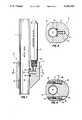
- FIG. 1is a fragmentary longitudinal view in section and elevation of one embodiment of a gas lift valve mandrel and gas lift valve installed on a coil tubing section;
- FIG. 2is a view in section along the line 2--2 of the gas lift valve mandrel and coil tubing shown in FIG. 1;
- FIG. 3is a fragmentary right side view in elevation of the gas lift valve mandrel and gas lift valve on the coil tubing as shown in FIG. 1;
- FIG. 4is a view in section of the gas lift valve mandrel along the line 4--4 of FIG. 3 rotated 90 degrees to the orientation of FIG. 1;
- FIG. 5is an inside view in perspective of the right mandrel body segment or valve adapter as illustrated in FIGS. 1, 2, and 4 showing the O-ring groove around the gas opening into the bore of the mandrel;
- FIG. 6is a view in section of the body segment along the line 6--6 of FIG. 5;
- FIG. 7is a fragmentary view in elevation of the coil tubing section on which the mandrel is installed showing reference marks used in the method of installation of the mandrel on the tubing;
- FIG. 8is a longitudinal view in section and elevation of another embodiment of the mandrel of the invention and a gas lift valve mounted on a section of coil tubing.
- a gas lift valve mandrel 10 embodying the features of the inventionis mounted on reeled or coil tubing 11 for supporting a gas lift valve 12 to admit lift gas into the tubing for producing a well through the tubing by the production method in which lift gas is introduced into the tubing to lift the column and aid in flowing the fluid from a well.
- the mandrel 10is formed in two body sections including a valve adaptor 13 and a retainer or clamp 14 secured together around the tubing 11.
- the adaptor 13 and the clamp 14 of the mandrelare two halves of the mandrel body secured together on the tubing to encircle the tubing as apparent in FIGS. 1, 2, and 4.
- the mandrelhas a longitudinal bore 15, one half of which is formed in the adapter 13, and the other half of which is formed in the clamp 14, so that the adapter and clamp fit together around the tubing with the tubing received in and extending through the bore 15 as evident in FIGS. 2 and 4.
- the adapter 13has an internal longitudinal upwardly opening threaded bore 20 for mounting the gas lift valve 12 on the adapter.
- the adapter bore 20opens into a vertical gas flow passage 21 which communicates with a horizontal gas flow passage 22 opening into the bore of the mandrel for flow of gas from a gas lift valve mounted on the mandrel into the tubing.
- An O-ring groove 23is provided in the surface of the portion of the bore 15 formed in the adapter 13 around the opening of the flow passage 22 into the mandrel bore, as best seen in FIG. 5.
- the groove 23is a circular groove uniformly machined into the inside surface of the portion of the mandrel bore in the adapter such that an O-ring installed in the groove will form a positive seal between the adapter and the outside surface of the tubing around an opening 25 in the tubing communicating the passage 22 with the interior of the tubing.
- the O-ring groove 23is formed in the adapter 13 around the open end of the passage 22 by a numerical programmed end mill shaping the O-ring groove to receive an O-ring 24.
- the millis operated relative to the longitudinal center line axis 26 of the cylindrical inside surface of the adapter 13 to form a groove 23 of uniform cross section.
- a radius line 27 from the axis 26extends along a centerline of the square cross section of the groove 23 at any location around the groove.
- the O-ringforms a positive seal with the outer surface of the reeled tubing around an opening 25 in the tubing communicating the adapter passage 22 with the interior of the tubing.
- the mandrelis provided with upper and lower slip teeth 30 and 31, respectively, around the bore within the adapter and clamp above and below the O-ring groove 23. The teeth 30 and 32 tightly grip the outer surface of the tubing 11 when the adapter and clamp are secured together around the tubing.
- the adapter 13has upper and lower lateral screw holes 32 on opposite sides of the bore 15 each of which has an enlarged outer end portion 33.
- the clamp 14has corresponding upper and lower lateral internally threaded screw holes 34 which match the bolt holes 32 in the adapter. Socket head cap screws 35 fit in the adapter screw holes 32 and are threaded into the clamp screw holes 34 to hold the adapter and clamp together around the tubing 11. As evident in FIG. 4, the enlarged outer end portions 33 of screw holes 32 permit the heads of the cap screws 35 to be countersunk in the adapter when the mandrel is mounted on the tubing.
- FIG. 7schematically illustrates a technique of properly locating the mandrel 10 on the coil tubing 11.
- a mark 40is made around the portion of the outer surface of the tubing 11 perpendicular to the longitudinal axis of the tubing.
- a mark 41is then inscribed along the outer surface of the tubing perpendicular to the mark 40 and extending longitudinally parallel with the longitudinal axis of the tubing.
- a mark 42is then inscribed in the outer surface of the tubing crossing the mark 41 at the known distance from the upper end of the mandrel 10 to the center of the lateral passage 22 in the mandrel adapter 13. The intersection of the mark 42 with the longitudinal mark 41 is the location of the center of the hole 25 in the tubing 11.
- the hole 25is then drilled in the tubing at the intersection of the mark 41 and 42.
- a mark 43is then inscribed along the longitudinal center line of the mandrel adapter 13 as shown in FIG. 3.
- the adapter 13is placed on the outer surface of the reeled tubing aligning the top end edge of the adapter with the mark 40 and the longitudinal center mark 43 on the adapter with the longitudinal mark 41 on the tubing.
- the lateral passage 22 in the adapteris aligned with the flow port or hole 25 in the tubing.
- the O-ring 24Prior to positioning the adapter 13 on the tubing surface, the O-ring 24 is placed in the O-ring groove 23 so that when the adapter is properly located on the tubing the O-ring engages the outer surface of the tubing for sealing between the adapter and the tubing surface around the adapter passage 22 and the tubing port 25.
- the mandrel clamp 14is positioned on the opposite side of the tubing in alignment with the adapter 13 and the socket heads cap screws 35 are placed in the screw holes 32 and screwed into the internally threaded screw holes 34 in the clamp until the adapter and clamp are tightly secured together on the tubing forming the mandrel 10.
- the slip teeth 30 and 31 within the bore of the mandrelengage the outer surface of the tubing securing the mandrel against longitudinal movement such as slippage along the tubing.
- the outer surface area of the tubingis rubbed smooth with emery cloth paying particular attention to the area around the port 25 in the tubing.
- the gas lift valve 12is secured into the mandrel by engaging the externally threaded lower end portion or an appropriate fitting of the gas lift valve into the internally threaded mandrel bore 20.
- FIG. 8illustrates a modification of the mandrel adapter 13 which permits a different method of mounting the mandrel on the tubing to be used.
- An internally threaded pipe plug hole 50is drilled through the outer surface of the adapter 13 into the flow passage 22 along the axis of the flow passage.
- the use of this modified form of the adapter 3 with the pipe plug hole 50eliminates the need for the mounting method utilizing the inscribed marks on the tubing surface as illustrated in FIG. 7.
- the modified adapter 13 and the clamp 14are secured together on the tubing with the O-ring in place in the O-ring groove 23. Either after positioning the mandrel on the tubing or before, a pipe plug 51 is screwed into the pipe plug hole 50.
- the mandrelmay be pressured tested by applying a pressure into the mandrel passages 21 and 22 through the internally threaded passage 20.
- the pipe plug 51is then removed and the port hole 25 in the tubing is then drilled by inserting a drill through the pipe plug hole 50 and the mandrel passage 22. After drilling the port 25, the pipe plug is replaced in the hole 50 sealing the pipe plug hole.
- the gas lift valve 12may then be mounted on or connected into the mandrel at the adapter 13 as illustrated.
- the use of the modified mandrel adapter illustrated in FIG. 8eliminates the necessity for the markings on the coil tubing described in FIG. 7 and thus, avoids any alignment problems between the port 25 and the tubing and the mandrel adapter passage 22.
- Mandrels 10 with gas lift valves 12may be mounted on the coil tubing at desired locations along the tubing as the tubing is run into a well using well known apparatus and techniques, such as a lubricator through which the mandrel and gas lift valves may be introduced into a well and standard equipment for running the coil tubing with the mandrel and valves attached into a well. If it is necessary to relocate the mandrels and gas lift valves, the spacing is readily changed by removing the mandrels, welding the ports 25 in the tubing closed, and remounting the mandrels and gas lift valves at other locations as desired.
- a gas lift valve mandrel in accordance with the inventionis inexpensive to manufacturer and can be very quickly installed.
- the structure of the mandrel and the installation procedurespermit gas lift valves to be quickly pulled and serviced by retrieving the coil tubing on which the mandrels are mounted.
- Conventional threaded production tubing required with prior art gas lift valve mandrelsis eliminated.
- the mandrelsmay be readily reused. If the spacing of the mandrels and gas lift valves needs changing, the mandrels are quickly removed and reinstalled at other locations along the length of the tubing.
Landscapes
- Engineering & Computer Science (AREA)
- Life Sciences & Earth Sciences (AREA)
- Geology (AREA)
- Mining & Mineral Resources (AREA)
- Physics & Mathematics (AREA)
- Environmental & Geological Engineering (AREA)
- Fluid Mechanics (AREA)
- General Life Sciences & Earth Sciences (AREA)
- Geochemistry & Mineralogy (AREA)
- Mechanical Engineering (AREA)
- Load-Engaging Elements For Cranes (AREA)
Abstract
Description
Claims (24)
Priority Applications (3)
| Application Number | Priority Date | Filing Date | Title |
|---|---|---|---|
| US07/706,944US5152343A (en) | 1991-05-29 | 1991-05-29 | Reeled tubing gas lift mandrel |
| GB9208968AGB2256245B (en) | 1991-05-29 | 1992-04-24 | Reeled tubing gas lift mandrel |
| CA 2068200CA2068200A1 (en) | 1991-05-29 | 1992-05-07 | Reeled tubing gas lift mandrel |
Applications Claiming Priority (1)
| Application Number | Priority Date | Filing Date | Title |
|---|---|---|---|
| US07/706,944US5152343A (en) | 1991-05-29 | 1991-05-29 | Reeled tubing gas lift mandrel |
Publications (1)
| Publication Number | Publication Date |
|---|---|
| US5152343Atrue US5152343A (en) | 1992-10-06 |
Family
ID=24839734
Family Applications (1)
| Application Number | Title | Priority Date | Filing Date |
|---|---|---|---|
| US07/706,944Expired - Fee RelatedUS5152343A (en) | 1991-05-29 | 1991-05-29 | Reeled tubing gas lift mandrel |
Country Status (3)
| Country | Link |
|---|---|
| US (1) | US5152343A (en) |
| CA (1) | CA2068200A1 (en) |
| GB (1) | GB2256245B (en) |
Cited By (14)
| Publication number | Priority date | Publication date | Assignee | Title |
|---|---|---|---|---|
| GB2264314A (en)* | 1992-02-24 | 1993-08-25 | Camco Int | Coiled tubing gas lift assembly |
| GB2281576A (en)* | 1993-09-03 | 1995-03-08 | Camco Int | Coiled tubing concentric gas lift assembly |
| US5411085A (en)* | 1993-11-01 | 1995-05-02 | Camco International Inc. | Spoolable coiled tubing completion system |
| US6442105B1 (en) | 1995-02-09 | 2002-08-27 | Baker Hughes Incorporated | Acoustic transmission system |
| US20060076139A1 (en)* | 2004-10-12 | 2006-04-13 | Conrad Greg A | Apparatus and Method for Increasing Well Production Using Surfactant Injection |
| US20060185840A1 (en)* | 2005-02-23 | 2006-08-24 | Conrad Greg A | Apparatus for monitoring pressure using capillary tubing |
| WO2009113872A3 (en)* | 2008-03-14 | 2010-08-12 | Statoilhydro, Asa | Device for fixing a valve to a tubular member |
| US20110194817A1 (en)* | 2010-02-05 | 2011-08-11 | Baker Hughes Incorporated | Spoolable signal conduction and connection line and method |
| US20110232921A1 (en)* | 2010-03-25 | 2011-09-29 | Baker Hughes Incorporated | Spoolable downhole control system and method |
| US20130220599A1 (en)* | 2012-02-24 | 2013-08-29 | Colin Gordon Rae | External Pressure Testing of Gas Lift Valve in Side-Pocket Mandrel |
| US20170130535A1 (en)* | 2015-11-06 | 2017-05-11 | Ge Oil & Gas Pressure Control Lp | Coiled tubing split-type running and retrievable clamp tool |
| CN107304661A (en)* | 2016-04-19 | 2017-10-31 | 中国石油天然气股份有限公司 | Single-flow valve assembly, gas lift valve, gas lift tool and integrated tubular column |
| CN110952963A (en)* | 2019-10-30 | 2020-04-03 | 中国石油化工股份有限公司 | Structure and method for producing tubular column with pressing-down gas lift |
| US11255133B2 (en) | 2018-11-08 | 2022-02-22 | Saudi Arabian Oil Company | Harness for intelligent completions |
Families Citing this family (1)
| Publication number | Priority date | Publication date | Assignee | Title |
|---|---|---|---|---|
| DE19524071C2 (en)* | 1994-07-12 | 1998-08-06 | Mannesmann Sachs Ag | Fastening device for a hydraulic connection to a tubular body |
Citations (8)
| Publication number | Priority date | Publication date | Assignee | Title |
|---|---|---|---|---|
| US2904058A (en)* | 1956-04-09 | 1959-09-15 | Otis Eng Co | Control valve for pipe strings |
| US3066690A (en)* | 1959-10-16 | 1962-12-04 | Camco Inc | Well injection and bleed valve |
| US3124151A (en)* | 1964-03-10 | lilly | ||
| US4628995A (en)* | 1985-08-12 | 1986-12-16 | Panex Corporation | Gauge carrier |
| US4844166A (en)* | 1988-06-13 | 1989-07-04 | Camco, Incorporated | Method and apparatus for recompleting wells with coil tubing |
| US5018575A (en)* | 1988-10-25 | 1991-05-28 | Mandrels, Inc. | Apparatus for reducing abrasion and corrosion in mandrels |
| US5033550A (en)* | 1990-04-16 | 1991-07-23 | Otis Engineering Corporation | Well production method |
| US5056599A (en)* | 1989-04-24 | 1991-10-15 | Walter B. Comeaux, III | Method for treatment of wells |
Family Cites Families (4)
| Publication number | Priority date | Publication date | Assignee | Title |
|---|---|---|---|---|
| US4029118A (en)* | 1975-07-03 | 1977-06-14 | Phillips Petroleum Company | Tapping apparatus and method |
| IT1136124B (en)* | 1980-02-14 | 1986-08-27 | Gino Ciccolallo | SOCKET FROM DERIVATION FROM PIPES INSTALLED WITH ORIENTATION DESIRE RATE OF THE VALVE EQUIPPED WITH PERFORATING ORGAN |
| GB2103321B (en)* | 1981-08-05 | 1985-09-11 | Barber And Company Limited Edw | Tapping pipe connections |
| US4789189A (en)* | 1986-02-28 | 1988-12-06 | Robertson Duane D | Pipe saddle |
- 1991
- 1991-05-29USUS07/706,944patent/US5152343A/ennot_activeExpired - Fee Related
- 1992
- 1992-04-24GBGB9208968Apatent/GB2256245B/ennot_activeExpired - Fee Related
- 1992-05-07CACA 2068200patent/CA2068200A1/ennot_activeAbandoned
Patent Citations (8)
| Publication number | Priority date | Publication date | Assignee | Title |
|---|---|---|---|---|
| US3124151A (en)* | 1964-03-10 | lilly | ||
| US2904058A (en)* | 1956-04-09 | 1959-09-15 | Otis Eng Co | Control valve for pipe strings |
| US3066690A (en)* | 1959-10-16 | 1962-12-04 | Camco Inc | Well injection and bleed valve |
| US4628995A (en)* | 1985-08-12 | 1986-12-16 | Panex Corporation | Gauge carrier |
| US4844166A (en)* | 1988-06-13 | 1989-07-04 | Camco, Incorporated | Method and apparatus for recompleting wells with coil tubing |
| US5018575A (en)* | 1988-10-25 | 1991-05-28 | Mandrels, Inc. | Apparatus for reducing abrasion and corrosion in mandrels |
| US5056599A (en)* | 1989-04-24 | 1991-10-15 | Walter B. Comeaux, III | Method for treatment of wells |
| US5033550A (en)* | 1990-04-16 | 1991-07-23 | Otis Engineering Corporation | Well production method |
Cited By (27)
| Publication number | Priority date | Publication date | Assignee | Title |
|---|---|---|---|---|
| GB2264314A (en)* | 1992-02-24 | 1993-08-25 | Camco Int | Coiled tubing gas lift assembly |
| GB2264314B (en)* | 1992-02-24 | 1995-06-28 | Camco Int | Coiled tubing gas lift assembly |
| GB2281576A (en)* | 1993-09-03 | 1995-03-08 | Camco Int | Coiled tubing concentric gas lift assembly |
| GB2281576B (en)* | 1993-09-03 | 1996-11-13 | Camco Int | Coiled tubing concentric gas lift assembly |
| US5411085A (en)* | 1993-11-01 | 1995-05-02 | Camco International Inc. | Spoolable coiled tubing completion system |
| USRE36723E (en)* | 1993-11-01 | 2000-06-06 | Camco International Inc. | Spoolable coiled tubing completion system |
| US6442105B1 (en) | 1995-02-09 | 2002-08-27 | Baker Hughes Incorporated | Acoustic transmission system |
| US20060076139A1 (en)* | 2004-10-12 | 2006-04-13 | Conrad Greg A | Apparatus and Method for Increasing Well Production Using Surfactant Injection |
| US7311144B2 (en)* | 2004-10-12 | 2007-12-25 | Greg Allen Conrad | Apparatus and method for increasing well production using surfactant injection |
| US20080066919A1 (en)* | 2004-10-12 | 2008-03-20 | Conrad Greg A | Apparatus and method for increasing well production using surfactant injection |
| US8695706B2 (en) | 2004-10-12 | 2014-04-15 | Six Degrees, Llc | Apparatus and device for delivering fluid downhole and increasing well production |
| US7909101B2 (en) | 2004-10-12 | 2011-03-22 | Nalco One Source, LLC | Apparatus and method for increasing well production |
| US20060185840A1 (en)* | 2005-02-23 | 2006-08-24 | Conrad Greg A | Apparatus for monitoring pressure using capillary tubing |
| GB2470691A (en)* | 2008-03-14 | 2010-12-01 | Statoil Asa | Device for fixing a valve to a tubular member |
| GB2470691B (en)* | 2008-03-14 | 2012-06-13 | Statoil Asa | Device for fixing a valve to a tubular member |
| WO2009113872A3 (en)* | 2008-03-14 | 2010-08-12 | Statoilhydro, Asa | Device for fixing a valve to a tubular member |
| US20110073313A1 (en)* | 2008-03-14 | 2011-03-31 | Statoil Asa | Device for fixing a valve to a tubular member |
| US8602658B2 (en) | 2010-02-05 | 2013-12-10 | Baker Hughes Incorporated | Spoolable signal conduction and connection line and method |
| US20110194817A1 (en)* | 2010-02-05 | 2011-08-11 | Baker Hughes Incorporated | Spoolable signal conduction and connection line and method |
| US8397828B2 (en)* | 2010-03-25 | 2013-03-19 | Baker Hughes Incorporated | Spoolable downhole control system and method |
| US20110232921A1 (en)* | 2010-03-25 | 2011-09-29 | Baker Hughes Incorporated | Spoolable downhole control system and method |
| US20130220599A1 (en)* | 2012-02-24 | 2013-08-29 | Colin Gordon Rae | External Pressure Testing of Gas Lift Valve in Side-Pocket Mandrel |
| US20170130535A1 (en)* | 2015-11-06 | 2017-05-11 | Ge Oil & Gas Pressure Control Lp | Coiled tubing split-type running and retrievable clamp tool |
| US10584549B2 (en)* | 2015-11-06 | 2020-03-10 | Ge Oil & Gas Pressure Control Lp | Coiled tubing split-type running and retrievable clamp tool |
| CN107304661A (en)* | 2016-04-19 | 2017-10-31 | 中国石油天然气股份有限公司 | Single-flow valve assembly, gas lift valve, gas lift tool and integrated tubular column |
| US11255133B2 (en) | 2018-11-08 | 2022-02-22 | Saudi Arabian Oil Company | Harness for intelligent completions |
| CN110952963A (en)* | 2019-10-30 | 2020-04-03 | 中国石油化工股份有限公司 | Structure and method for producing tubular column with pressing-down gas lift |
Also Published As
| Publication number | Publication date |
|---|---|
| GB2256245B (en) | 1995-02-01 |
| CA2068200A1 (en) | 1992-11-30 |
| GB9208968D0 (en) | 1992-06-10 |
| GB2256245A (en) | 1992-12-02 |
Similar Documents
| Publication | Publication Date | Title |
|---|---|---|
| US5152343A (en) | Reeled tubing gas lift mandrel | |
| EP2102446B1 (en) | Wellhead assembly and method for an injection tubing string | |
| CA1304285C (en) | Deployment/retrieval method and apparatus for well tools used with coiled tubing | |
| USRE39509E1 (en) | Top entry sub arrangement | |
| US4681158A (en) | Casing alignment tool | |
| CA2268557C (en) | Method and apparatus for dual string well tree isolation | |
| US4681162A (en) | Borehole drill pipe continuous side entry or exit apparatus and method | |
| BR0316189B1 (en) | GUIDANCE SYSTEM AND METHOD FOR A SUBSEA WELL | |
| US7913754B2 (en) | Wellhead assembly and method for an injection tubing string | |
| US6988553B2 (en) | Horizontal spool tree wellhead system and method | |
| EP3784876B1 (en) | Systems, devices and methods for orienting a production outlet of a subsea production tree | |
| US4605065A (en) | Method and apparatus for monitoring well tubing fluid | |
| BR112012020617A2 (en) | valve system for use in a well bore | |
| US11719064B2 (en) | Completing wells | |
| US20040079532A1 (en) | Wellhead systems | |
| US20240368956A1 (en) | Modular Head for Well Tubulars | |
| US7832480B1 (en) | Apparatus and method for extracting a tubular string from a bore hole | |
| US4641998A (en) | Underwater connection apparatus | |
| US20040231835A1 (en) | Tubing hanger orientation device | |
| US20050067167A1 (en) | Radial penetrator assembly and method | |
| WO2004083598A1 (en) | Tubing hanger orientation device | |
| US8863832B2 (en) | Orientable eccentric downhole assembly | |
| US11680458B2 (en) | Method for replacing a chemical injection valve connected to a well head via an injection line housing and injection line plugging tool | |
| CA1238574A (en) | Casing alignment tool |
Legal Events
| Date | Code | Title | Description |
|---|---|---|---|
| AS | Assignment | Owner name:OTIS ENGINEERING CORPORATION Free format text:ASSIGNMENT OF ASSIGNORS INTEREST.;ASSIGNOR:KILGORE, MARION D.;REEL/FRAME:005763/0321 Effective date:19910709 | |
| AS | Assignment | Owner name:HALLIBURTON COMPANY, TEXAS Free format text:MERGER;ASSIGNOR:OTIS ENGINEERING CORPORATION;REEL/FRAME:006779/0356 Effective date:19930624 | |
| FEPP | Fee payment procedure | Free format text:PAYOR NUMBER ASSIGNED (ORIGINAL EVENT CODE: ASPN); ENTITY STATUS OF PATENT OWNER: LARGE ENTITY | |
| FPAY | Fee payment | Year of fee payment:4 | |
| AS | Assignment | Owner name:CAMCO INTERNATIONAL, INC., TEXAS Free format text:ASSIGNMENT OF ASSIGNORS INTEREST;ASSIGNOR:HALLIBURTON ENERGY SERIVCES, INC.;REEL/FRAME:009089/0174 Effective date:19971009 | |
| AS | Assignment | Owner name:CAMCO INTERNATIONAL, INC., TEXAS Free format text:ASSIGNMENT OF ASSIGNORS INTEREST;ASSIGNOR:HALLIBURTON ENERGY SERVICES, INC.;REEL/FRAME:008753/0782 Effective date:19971009 | |
| FPAY | Fee payment | Year of fee payment:8 | |
| REMI | Maintenance fee reminder mailed | ||
| LAPS | Lapse for failure to pay maintenance fees | ||
| STCH | Information on status: patent discontinuation | Free format text:PATENT EXPIRED DUE TO NONPAYMENT OF MAINTENANCE FEES UNDER 37 CFR 1.362 | |
| FP | Lapsed due to failure to pay maintenance fee | Effective date:20041006 |