US5152280A - Bone support device - Google Patents
Bone support deviceDownload PDFInfo
- Publication number
- US5152280A US5152280AUS07/573,184US57318490AUS5152280AUS 5152280 AUS5152280 AUS 5152280AUS 57318490 AUS57318490 AUS 57318490AUS 5152280 AUS5152280 AUS 5152280A
- Authority
- US
- United States
- Prior art keywords
- articulation
- hinges
- plane
- pair
- rotation
- Prior art date
- Legal status (The legal status is an assumption and is not a legal conclusion. Google has not performed a legal analysis and makes no representation as to the accuracy of the status listed.)
- Expired - Lifetime
Links
Images

Classifications
- A—HUMAN NECESSITIES
- A61—MEDICAL OR VETERINARY SCIENCE; HYGIENE
- A61B—DIAGNOSIS; SURGERY; IDENTIFICATION
- A61B17/00—Surgical instruments, devices or methods
- A61B17/56—Surgical instruments or methods for treatment of bones or joints; Devices specially adapted therefor
- A61B17/58—Surgical instruments or methods for treatment of bones or joints; Devices specially adapted therefor for osteosynthesis, e.g. bone plates, screws or setting implements
- A61B17/60—Surgical instruments or methods for treatment of bones or joints; Devices specially adapted therefor for osteosynthesis, e.g. bone plates, screws or setting implements for external osteosynthesis, e.g. distractors, contractors
- A61B17/64—Devices extending alongside the bones to be positioned
- A61B17/6458—Devices extending alongside the bones to be positioned with pin-clamps fixed at ends of connecting element
Definitions
- the present inventionrelates to a bone support device for supporting fragments of bone, in particular of fractured bones of the human body.
- Said fractured bonesmust be kept in a presettable relative position, so as to allow the natural process of knitting of the bone fragments in the best possible manner.
- the devicecomprises a first member adapted to be rigidly connected to the first of said bone fragments and a second member adapted to be rigidly connected to the second of said bone fragments.
- the rigid couplingsare provided by means of screws which penetrate in adapted holes provided in the bone fragments.
- the devicefurthermore comprises an adjustable articulated central body which is connected to the first member and to the second member. The articulated central body allows to adjust the relative position of the first member with respect to the second member and to rigidly lock this relative position at a point which is particularly suitable to obtain the perfect knitting of the bone fragments.
- This relative locked positioncan in certain cases be released during the healing process to allow a single degree of freedom of release.
- This single degree of freedom of releaseallows the translatory motion of the first member with respect to the second member which is directed substantially along the axis of the fractured bone. It has in fact been observed that this single degree of freedom of release allows a "dynamic” knitting of the bone fragments which produces a greater strength of the knitted bone. It has in fact been observed that "static" knitting, provided when the two bone fragments are rigidly locked in their relative position, provides a more fragile final knitting.
- the relative arrangement of the two fractured bone fragments and therefore the corresponding relative arrangement of the first and second membersare performed by a surgeon, who can control the position of the two bone fragments by virtue of detection means such as for example X-rays.
- detection meanssuch as for example X-rays. Since said detection means allow to detect the position of the two bone fragments on a single plane, at least two different detections, taken along two different planes of exposure to radiation, are required, so as to verify that the position of the two bone fragments is correct in the three spatial dimensions. Said two detections can be performed on two planes which are inclined at 90° with respect to one another.
- said known devicesentail some problems: first of all, the need to perform two detections, for example on two planes orientated at 90° with respect to one another, entails difficult problems for the physician, since the position defined on one plane is unavoidably modified when an attempt is made to adjust the position on the second detection plane. This entails the problem of having to perform multiple successive checks between the two detection planes, so as to ensure that the position is correct. This problem is increased by the fact that the radiation useful for performing the checks, such as for example X rays, are harmful for the physician and for the patient.
- the aim of the present inventionis therefore to eliminate all the above described disadvantages.
- An object of the inventionis to allow to obtain the relative position of the fractured bone fragments with great precision and speed.
- Another object of the inventionis to allow a particularly simple and intuitive "friendly" use which can be learned without trouble by orthopedists without requiring particular specific training.
- Not least object of the inventionis to minimize the time of exposure to harmful radiation during the relative positioning of the two fractured bone fragments.
- the device according to the inventionwhich comprises a first member adapted to be rigidly connected to the first bone fragment, a second member adapted to be rigidly connected to the second bone fragment, and an adjustable articulated central body connected to said first member and to said second member, said articulated central body allowing to adjust the position of said first member with respect to said second member and to rigidly lock said position; characterized in that said articulated central body comprises:
- first articulation meanswhich allow the rotation of said first member and of said second member on a first articulation plane
- second articulation meanswhich allow the rotation of said first member and of said second member on a second articulation plane
- said first articulation means and said second articulation meansbeing adjustable and lockable independently of one another, so that the rotations of said first member and of said second member on said first articulation plane and on said second articulation plane can be adjusted independently for each of said articulation planes and the adjustment of said first articulation plane does not interfere with the adjustment of said second articulation plane and vice versa.
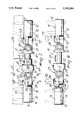
- FIG. 1is a perspective view of the first embodiment of the invention
- FIG. 2is a perspective view of an enlarged detail of FIG. 1;
- FIG. 3is a plan view of the device of FIG. 1;
- FIG. 4is a sectional view taken along the plane IV--IV of FIG. 3;
- FIG. 5is a sectional view taken along the plane V--V of FIG. 3, and
- FIG. 6is a plan view of the device according to the second embodiment of the invention.
- the device according to the inventioncomprises a first member 10 adapted to be connected to the first bone fragment 11.
- the rigid coupling between the first member 10 and the bone fragment 11is provided by means of screws 12 which penetrate in adapted holes provided on the bone fragment 11.
- the first member 10is composed of two elements 13 and 14 which can be mutually coupled so as to lock the screws in position.
- the second member 15is shaped similarly to the first member 10, so that it can be rigidly connected to the second bone fragment 16.
- the articulated central body 17connects the first member 10 to the second member 15 and comprises first articulation means 18 and 19 and second articulation means 27 and 28.
- Said first articulation means 18 and 19allow the rotation of the first member 10 with respect to the second member 15 on a first articulation plane schematically represented by the arrows 22 and 23.
- said first articulation planeis perpendicular to the axis of the first pair of hinges 18 and 19.
- the hinge 18is illustrated; said hinge is formed by the bolt 24 which engages the first member 10 and the connecting body 26.
- the second hinge 19 of the first pair of hingesis formed in a similar manner.
- the configuration of the connecting body 26is illustrated in detail with particular reference to FIG. 2.
- the first articulation means 18, 19are adjustable independently of the other articulation means simply by acting on the bolts 24 and 25. The simple locking of said bolts allows to lock the first articulation means and therefore to adjust the position of the first member 10 with respect to the second member 15 on the first articulation plane defined by the arrows 22 and 23.
- the second articulation means 27 and 28comprise the second pair of hinges 27 and 28 which allows to adjust the rotation of the first member 10 with respect to the second member 15 about a second articulation plane defined in particular by the arrows 29 and 30.
- the hinge 27is illustrated with particular reference to FIG. 5, wherein the bolt 31 which engages the connecting body 26 and the element 32 is illustrated.
- the second hinge 28 of the second pair of hingesis configured in a similar manner.
- the second articulation means 27 and 28are adjustable independently of the first articulation means 18 and 19 simply by acting on the bolts 31 and 33, which can be easily tightened so as to lock the position of the first member 10 with respect to the second member 15 in the second articulation plane.
- the first articulation plane defined by the arrows 22 and 23is inclined at 90° with respect to the second articulation plane defined by the arrows 29 and 30.
- Said 90° inclinationis determined by the configuration of the connecting bodies 26 which have connecting holes 34 and 35 the axes whereof are inclined at 90°, as illustrated in particular in FIG. 2.
- the axes of the screws 12 adapted to be inserted in the bone fragmentsare preferably offset so as to be inclined with respect to the first articulation plane 22, 23 and to the second articulation plane 29, 30. More preferably, said inclination is at 45°. In particular, said 45°-inclination is allowed by the inclination of the supporting holes of the bolt 24 with respect to the supporting holes of the screws 12, as provided on the first member 10. This is similarly true for the inclination of the supporting hole of the bolt 25 and of the screws 12 of the second member 15. Said holes are mutually offset by 45°.
- Each of the hinges 18, 19 of the first pair of hinges and each of the hinges 27 and 28 of the second pair of hingeshas a single degree of freedom, indicated respectively by the rotation of the arrows 22, 23, 29 and 30.
- Each hinge 27 and 28 of the second pair of hingesis respectively connected to the first articulation means 18 and 19 by means of the connecting bodies 26.
- the elements 32 and 40 of the second pair of hingesare connected to one another by means of third articulation means, represented by the arrow 41, which allow the relative approach and spacing of the axes of the second pair of hinges.
- the third articulation meanscomprise a translatory joint which can be locked by means of the bolt 42.
- the axial sliding 41allows a dynamic knitting of the fractured bones, allowing an axial movement of the two bone fragments 11 and 16.
- fourth articulation means 43are provided which allow the rotation of the first member 10 with respect to the second member 15 in the direction indicated by the arrow 44.
- Said fourth articulation meansare in practice used only for slight rotations of the first member with respect to the second member to compensate imprecisions due to the insertion of the screws in the bone fragments 11 and 16.
- the arrow 44indicates the rotation about an axis of rotation which is substantially parallel to the axis of the bone fragments.
- the fourth articulation meansmutually connect the elements 32 and 40 of the second pair of hinges 27 and 28.
- the first articulation plane and the second articulation planeare defined with the approximation due to the rotation allowed by the fourth articulation means.
- Said rotationin fact tends to offset the axes of the hinges which are proximate to the first member 10 with respect to the axes of the hinges which are proximate to the second member 15.
- said rotation due to the fourth articulation meansis in practice always very small, the resulting approximation is sufficient in practice.
- said figureillustrates a second embodiment of the invention which is differentiated from the first embodiment only for the position of the fourth articulation means, which according to said second embodiment connect the first member 10 to the first articulation means and in particular to the hinge 18.
- the fourth articulation meansallow the rotation of the first member 10 with respect to the second member 15 about an axis which is substantially parallel to the axis of the bone fragments 11 and 16; said rotation is indicated in particular by the arrow 50.
- the first articulation plane and the second articulation planeare defined with maximum precision, since the fourth articulation means do not affect the relative position of the axes of rotation of the hinges of the first articulation means and of the second articulation means.
- the central articulated body 17has six degrees of freedom which are represented by the arrows 22, 29, 44 or 50, 41, 30 and 23 and are individually lockable respectively by means of the bolts 24, 31, 52 or 60, 42, 33, 25.
Landscapes
- Health & Medical Sciences (AREA)
- Orthopedic Medicine & Surgery (AREA)
- Life Sciences & Earth Sciences (AREA)
- Surgery (AREA)
- Medical Informatics (AREA)
- General Health & Medical Sciences (AREA)
- Biomedical Technology (AREA)
- Heart & Thoracic Surgery (AREA)
- Nuclear Medicine, Radiotherapy & Molecular Imaging (AREA)
- Molecular Biology (AREA)
- Animal Behavior & Ethology (AREA)
- Engineering & Computer Science (AREA)
- Public Health (AREA)
- Veterinary Medicine (AREA)
- Surgical Instruments (AREA)
- Prostheses (AREA)
- Materials For Medical Uses (AREA)
- Orthopedics, Nursing, And Contraception (AREA)
Abstract
Description
Claims (29)
Applications Claiming Priority (2)
| Application Number | Priority Date | Filing Date | Title |
|---|---|---|---|
| IT19010A/89 | 1989-01-04 | ||
| IT8919010AIT1228305B (en) | 1989-01-04 | 1989-01-04 | BONE SUPPORT DEVICE. |
Publications (1)
| Publication Number | Publication Date |
|---|---|
| US5152280Atrue US5152280A (en) | 1992-10-06 |
Family
ID=11153828
Family Applications (1)
| Application Number | Title | Priority Date | Filing Date |
|---|---|---|---|
| US07/573,184Expired - LifetimeUS5152280A (en) | 1989-01-04 | 1989-12-20 | Bone support device |
Country Status (8)
| Country | Link |
|---|---|
| US (1) | US5152280A (en) |
| EP (1) | EP0404897B1 (en) |
| JP (1) | JP2725884B2 (en) |
| AT (1) | ATE152596T1 (en) |
| DE (1) | DE68928032T2 (en) |
| ES (1) | ES2100879T3 (en) |
| IT (1) | IT1228305B (en) |
| WO (1) | WO1990007305A1 (en) |
Cited By (67)
| Publication number | Priority date | Publication date | Assignee | Title |
|---|---|---|---|---|
| US5376090A (en)* | 1991-07-12 | 1994-12-27 | Orthofix S.R.L. | Clamping coupling |
| US5405347A (en)* | 1993-02-12 | 1995-04-11 | Zimmer, Inc. | Adjustable connector for external fixation rods |
| US5429637A (en)* | 1991-11-08 | 1995-07-04 | Hardy; Jean M. | External modular fixator for immobilization of a fracture |
| US5662648A (en)* | 1993-03-15 | 1997-09-02 | Orthofix S.R.L. | Method and apparatus for the external setting of fractures |
| US5662650A (en)* | 1995-05-12 | 1997-09-02 | Electro-Biology, Inc. | Method and apparatus for external fixation of large bones |
| US5743898A (en)* | 1995-05-12 | 1998-04-28 | Electro-Biology, Inc. | Method and apparatus for external fixation of small bones |
| WO1998046156A1 (en)* | 1997-04-11 | 1998-10-22 | Keele University | Fracture reduction device |
| US5827282A (en)* | 1991-07-12 | 1998-10-27 | Orthofix S.R.1. | Clamping coupling |
| EP0858780A3 (en)* | 1997-02-13 | 1999-05-06 | ORTHOFIX S.r.l. | Orthopaedic apparatus, particularly for the surgical correction of bone deformations |
| DE19746687A1 (en)* | 1997-10-22 | 1999-05-06 | Gerd Dr Werding | Device for external fixation of broken bones, especially the extremities |
| EP0858781A3 (en)* | 1997-02-14 | 1999-05-12 | ORTHOFIX S.r.l. | Orthopaedic device for the gradual correction of limbs |
| US5976125A (en)* | 1995-08-29 | 1999-11-02 | The Cleveland Clinic Foundation | External distractor/fixator for the management of fractures and dislocations of interphalangeal joints |
| US5976136A (en)* | 1998-05-11 | 1999-11-02 | Electro Biology, Inc. | Method and apparatus for external bone fixator |
| US5993448A (en)* | 1995-10-02 | 1999-11-30 | Remmler; Daniel J. | Implantable apparatus, matrix and method for correction of craniofacial bone deformities |
| WO2000038974A1 (en) | 1998-12-23 | 2000-07-06 | Danieli, Giovanna | Device for disengaging buoys and transponders from submarine pipelines |
| US6162224A (en)* | 1995-02-15 | 2000-12-19 | Acumed, Inc. | External fixator for repairing fractures of distal radius and wrist |
| US6171309B1 (en) | 1995-02-15 | 2001-01-09 | Acumed, Inc. | External fixator for repairing fractures of distal radius and wrist |
| US6245071B1 (en) | 1999-03-10 | 2001-06-12 | Synthes (U.S.A.) | External fixation device for bone |
| US6409729B1 (en) | 1998-05-19 | 2002-06-25 | Synthes (Usa) | Clamp assembly for an external fixation system |
| US6565564B2 (en) | 2000-12-14 | 2003-05-20 | Synthes U.S.A. | Multi-pin clamp and rod attachment |
| US20030109879A1 (en)* | 1994-12-05 | 2003-06-12 | Orsak James E. | External fixator for distal radius fractures |
| US6716212B1 (en)* | 2002-01-25 | 2004-04-06 | Tyrone Sam Pickens | Universal modular external fixation system |
| US20040138659A1 (en)* | 2003-01-10 | 2004-07-15 | Ed Austin | External fixation apparatus and method |
| US20040249375A1 (en)* | 2003-06-03 | 2004-12-09 | The John M. Agee Trust | External fixator for colles' fracture |
| US20050245939A1 (en)* | 2002-06-14 | 2005-11-03 | Joseph Ferrante | Device and methods for placing external fixation elements |
| US20050261680A1 (en)* | 2001-03-28 | 2005-11-24 | Imperial College Innovations Ltd. | Bone fixated, articulated joint load control device |
| US7004943B2 (en) | 2002-02-04 | 2006-02-28 | Smith & Nephew, Inc. | Devices, systems, and methods for placing and positioning fixation elements in external fixation systems |
| US7048735B2 (en) | 2002-02-04 | 2006-05-23 | Smith & Nephew | External fixation system |
| US7147640B2 (en) | 2003-03-12 | 2006-12-12 | Acumed Llc | External fixator |
| US7261713B2 (en) | 2001-10-09 | 2007-08-28 | Synthes (Usa) | Adjustable fixator |
| US20080275565A1 (en)* | 2007-05-01 | 2008-11-06 | Exploramed Nc4, Inc. | Adjustable absorber designs for implantable device |
| US20080275567A1 (en)* | 2007-05-01 | 2008-11-06 | Exploramed Nc4, Inc. | Extra-Articular Implantable Mechanical Energy Absorbing Systems |
| US20080275560A1 (en)* | 2007-05-01 | 2008-11-06 | Exploramed Nc4, Inc. | Femoral and tibial base components |
| US7507240B2 (en) | 2005-03-18 | 2009-03-24 | Ron Anthon Olsen | Adjustable splint for osteosynthesis |
| US20090125068A1 (en)* | 2003-02-28 | 2009-05-14 | Estrada Jr Hector Mark | Apparatus for Dynamic External Fixation of Distal Radius and Wrist Fractures |
| US7611540B2 (en) | 2007-05-01 | 2009-11-03 | Moximed, Inc. | Extra-articular implantable mechanical energy absorbing systems and implantation method |
| CN101002696B (en)* | 2005-08-03 | 2010-05-12 | 香港理工大学 | Bone positioning device and system |
| US20100137996A1 (en)* | 2007-05-01 | 2010-06-03 | Moximed, Inc. | Femoral and tibial base components |
| US7731738B2 (en) | 2005-12-09 | 2010-06-08 | Orthopro, Llc | Cannulated screw |
| US20110093080A1 (en)* | 2009-10-20 | 2011-04-21 | Slone Clinton N | Extra-articular implantable mechanical energy absorbing assemblies having two deflecting members and methods |
| US20110202138A1 (en)* | 2009-08-27 | 2011-08-18 | The Foundry Llc | Method and Apparatus for Force Redistribution in Articular Joints |
| US8123805B2 (en) | 2007-05-01 | 2012-02-28 | Moximed, Inc. | Adjustable absorber designs for implantable device |
| USD663030S1 (en) | 2011-06-14 | 2012-07-03 | Styker Trauma SA | Fixation clamp |
| USD682426S1 (en) | 2011-06-14 | 2013-05-14 | Stryker Trauma Sa | Fixation clamp |
| USD683461S1 (en) | 2010-12-14 | 2013-05-28 | Stryker Trauma Sa | Hinge coupling |
| US8523948B2 (en) | 2009-10-20 | 2013-09-03 | Moximed, Inc. | Extra-articular implantable mechanical energy absorbing assemblies having a tension member, and methods |
| US8685023B2 (en) | 2010-12-14 | 2014-04-01 | Stryker Trauma Sa | Fixation clamp |
| US8709090B2 (en) | 2007-05-01 | 2014-04-29 | Moximed, Inc. | Adjustable absorber designs for implantable device |
| USD704840S1 (en) | 2010-12-14 | 2014-05-13 | Stryker Trauma Sa | Hinge coupling |
| US8758343B2 (en) | 2005-04-27 | 2014-06-24 | DePuy Synthes Products, LLC | Bone fixation apparatus |
| US8827998B2 (en) | 2010-12-14 | 2014-09-09 | Stryker Trauma Sa | Fixation clamp |
| US8845724B2 (en) | 2009-08-27 | 2014-09-30 | Cotera, Inc. | Method and apparatus for altering biomechanics of the articular joints |
| US8894714B2 (en) | 2007-05-01 | 2014-11-25 | Moximed, Inc. | Unlinked implantable knee unloading device |
| USD720853S1 (en) | 2010-12-14 | 2015-01-06 | Stryker Trauma Sa | Fixation clamp |
| US8945129B2 (en) | 2010-12-14 | 2015-02-03 | Stryker Trauma Sa | Fixation clamp with thumbwheel |
| US9044270B2 (en) | 2011-03-29 | 2015-06-02 | Moximed, Inc. | Apparatus for controlling a load on a hip joint |
| US9398957B2 (en) | 2007-05-01 | 2016-07-26 | Moximed, Inc. | Femoral and tibial bases |
| US9468466B1 (en) | 2012-08-24 | 2016-10-18 | Cotera, Inc. | Method and apparatus for altering biomechanics of the spine |
| US9668868B2 (en) | 2009-08-27 | 2017-06-06 | Cotera, Inc. | Apparatus and methods for treatment of patellofemoral conditions |
| US9770272B2 (en) | 2012-12-12 | 2017-09-26 | Wright Medical Technology, Inc. | Orthopedic compression/distraction device |
| US9861408B2 (en) | 2009-08-27 | 2018-01-09 | The Foundry, Llc | Method and apparatus for treating canine cruciate ligament disease |
| US9907645B2 (en) | 2007-05-01 | 2018-03-06 | Moximed, Inc. | Adjustable absorber designs for implantable device |
| US9936975B2 (en) | 2014-09-09 | 2018-04-10 | Integra Lifesciences Corporation | External fixation system |
| US20180310962A1 (en)* | 2015-09-29 | 2018-11-01 | Orthofix S.R.L. | Walking skates system removably coupled to an external ring fixation system |
| US10349980B2 (en) | 2009-08-27 | 2019-07-16 | The Foundry, Llc | Method and apparatus for altering biomechanics of the shoulder |
| US10973550B2 (en)* | 2018-05-01 | 2021-04-13 | Raymond K. Wurapa | Monoplanar hinged adjustable external fixator for bone fixation and distraction |
| US11166750B1 (en) | 2021-05-13 | 2021-11-09 | Raymond K. Wurapa | Monoplanar device for stabilizing and distracting an anatomical joint |
Families Citing this family (12)
| Publication number | Priority date | Publication date | Assignee | Title |
|---|---|---|---|---|
| IT1236172B (en)* | 1989-11-30 | 1993-01-11 | Franco Mingozzi | EXTERNAL FIXER FOR THE TREATMENT OF LONG BONE FRACTURES OF THE LIMBS. |
| GB9002033D0 (en)* | 1990-01-30 | 1990-03-28 | Sheffield City Council | Bone fixation |
| ES2043487B1 (en)* | 1991-04-30 | 1994-06-16 | Levante Ind Quirurgicas | NEW EXTERNAL FIXER FOR FRACTURE REDUCTION. |
| FR2688399A1 (en)* | 1992-03-12 | 1993-09-17 | Fixano Sa | External fixator for percutaneous osteosynthesis of extra-capsular fractures of the upper end of the femur or pertrochanterian fractures |
| GB9320565D0 (en)* | 1993-10-06 | 1993-11-24 | Biomet Ltd | Bone fixator |
| GB2300357A (en)* | 1995-05-01 | 1996-11-06 | Biomet Ltd | Bone fixation system with data logging device |
| IT1289103B1 (en)* | 1996-05-15 | 1998-09-25 | Orthofix Srl | COMPACT EXTERNAL FIXER |
| IT1298413B1 (en)* | 1997-05-21 | 2000-01-05 | Orthofix Srl | EXTERNAL MINIFIXER DEVICE FOR SMALL BONE TREATMENT |
| CH705390B1 (en)* | 2004-05-25 | 2013-02-28 | Orlando Da Rold | Invasive distractor. |
| JP4594268B2 (en)* | 2006-04-07 | 2010-12-08 | 有限会社メディコ・インターメディア | Bone extender |
| CN102657565B (en)* | 2011-11-28 | 2017-04-26 | 董谢平 | Universal-joint-type fracture external-fixation device |
| US10314618B2 (en) | 2014-07-25 | 2019-06-11 | The General Hospital Corporation | System and method for an external hip fixator |
Citations (13)
| Publication number | Priority date | Publication date | Assignee | Title |
|---|---|---|---|---|
| US2391537A (en)* | 1943-09-27 | 1945-12-25 | Anderson Roger | Ambulatory rotating reduction and fixation splint |
| DE2718515A1 (en)* | 1976-04-30 | 1977-11-10 | Nat Res Dev | ORTHOPEDIC FIXING DEVICE |
| DE2832283A1 (en)* | 1977-07-22 | 1979-02-15 | Giulio Gentile | JOINT SYSTEM FOR CONNECTING DEVICES THAT HAVE A HOLDING EFFECT ON BONE TISSUE |
| US4273116A (en)* | 1978-06-27 | 1981-06-16 | Claude Chiquet | Device for external fixation of bone fragments |
| US4312336A (en)* | 1978-11-10 | 1982-01-26 | Orthofix S.R.1. | External axial fixation unit |
| US4483334A (en)* | 1983-04-11 | 1984-11-20 | Murray William M | External fixation device |
| EP0153546A1 (en)* | 1984-01-19 | 1985-09-04 | Synthes Ag Chur | Fixation apparatus for immobilizing bone fragments |
| WO1986002822A1 (en)* | 1984-11-08 | 1986-05-22 | Enrico Castaman | Apparatus for the stabilization of bone fractures |
| DE3543042A1 (en)* | 1984-12-18 | 1986-06-19 | Orthofix S.r.l., Verona | ORTHOPEDIC DEVICE FOR AXIAL EXTERNAL FIXING |
| US4620533A (en)* | 1985-09-16 | 1986-11-04 | Pfizer Hospital Products Group Inc. | External bone fixation apparatus |
| DE3701533A1 (en)* | 1987-01-21 | 1988-08-04 | Medi System Gmbh | OSTEOSYNTHESIS TOOLS |
| US4895141A (en)* | 1984-04-26 | 1990-01-23 | Harrington Arthritis Research Center | Unilateral external fixation device |
| US4944743A (en)* | 1987-10-07 | 1990-07-31 | Mecron Medizinische Produkte Gmbh | Spinal Fixation device |
Family Cites Families (2)
| Publication number | Priority date | Publication date | Assignee | Title |
|---|---|---|---|---|
| JPS53127834A (en)* | 1977-04-12 | 1978-11-08 | Nippon Kayaku Co Ltd | Anti-tumor preparation |
| JPS5414777A (en)* | 1977-07-06 | 1979-02-03 | Hitachi Ltd | Alarm device |
- 1989
- 1989-01-04ITIT8919010Apatent/IT1228305B/enactive
- 1989-12-20WOPCT/EP1989/001581patent/WO1990007305A1/enactiveIP Right Grant
- 1989-12-20USUS07/573,184patent/US5152280A/ennot_activeExpired - Lifetime
- 1989-12-20EPEP90900149Apatent/EP0404897B1/ennot_activeExpired - Lifetime
- 1989-12-20ATAT90900149Tpatent/ATE152596T1/enactive
- 1989-12-20DEDE68928032Tpatent/DE68928032T2/ennot_activeExpired - Fee Related
- 1989-12-20ESES90900149Tpatent/ES2100879T3/ennot_activeExpired - Lifetime
- 1989-12-20JPJP2500806Apatent/JP2725884B2/ennot_activeExpired - Fee Related
Patent Citations (18)
| Publication number | Priority date | Publication date | Assignee | Title |
|---|---|---|---|---|
| US2391537A (en)* | 1943-09-27 | 1945-12-25 | Anderson Roger | Ambulatory rotating reduction and fixation splint |
| DE2718515A1 (en)* | 1976-04-30 | 1977-11-10 | Nat Res Dev | ORTHOPEDIC FIXING DEVICE |
| US4135505A (en)* | 1976-04-30 | 1979-01-23 | National Research Development Corporation | Orthopaedic fracture fixing apparatus |
| DE2832283A1 (en)* | 1977-07-22 | 1979-02-15 | Giulio Gentile | JOINT SYSTEM FOR CONNECTING DEVICES THAT HAVE A HOLDING EFFECT ON BONE TISSUE |
| US4273116A (en)* | 1978-06-27 | 1981-06-16 | Claude Chiquet | Device for external fixation of bone fragments |
| US4312336A (en)* | 1978-11-10 | 1982-01-26 | Orthofix S.R.1. | External axial fixation unit |
| US4483334A (en)* | 1983-04-11 | 1984-11-20 | Murray William M | External fixation device |
| US4714076A (en)* | 1984-01-19 | 1987-12-22 | Synthes | Device for the setting of bone segments |
| EP0153546A1 (en)* | 1984-01-19 | 1985-09-04 | Synthes Ag Chur | Fixation apparatus for immobilizing bone fragments |
| US4895141A (en)* | 1984-04-26 | 1990-01-23 | Harrington Arthritis Research Center | Unilateral external fixation device |
| WO1986002822A1 (en)* | 1984-11-08 | 1986-05-22 | Enrico Castaman | Apparatus for the stabilization of bone fractures |
| US4745913A (en)* | 1984-11-08 | 1988-05-24 | Enrico Castaman | Apparatus for the stabilization of bone fractures |
| DE3543042A1 (en)* | 1984-12-18 | 1986-06-19 | Orthofix S.r.l., Verona | ORTHOPEDIC DEVICE FOR AXIAL EXTERNAL FIXING |
| US4621627A (en)* | 1984-12-18 | 1986-11-11 | Orthofix S.R.L. | External axial fixation device |
| US4620533A (en)* | 1985-09-16 | 1986-11-04 | Pfizer Hospital Products Group Inc. | External bone fixation apparatus |
| DE3701533A1 (en)* | 1987-01-21 | 1988-08-04 | Medi System Gmbh | OSTEOSYNTHESIS TOOLS |
| US4988349A (en)* | 1987-01-21 | 1991-01-29 | Orthofix S.R.L. | Device for osteosynthesis |
| US4944743A (en)* | 1987-10-07 | 1990-07-31 | Mecron Medizinische Produkte Gmbh | Spinal Fixation device |
Cited By (139)
| Publication number | Priority date | Publication date | Assignee | Title |
|---|---|---|---|---|
| US5827282A (en)* | 1991-07-12 | 1998-10-27 | Orthofix S.R.1. | Clamping coupling |
| US5376090A (en)* | 1991-07-12 | 1994-12-27 | Orthofix S.R.L. | Clamping coupling |
| US5429637A (en)* | 1991-11-08 | 1995-07-04 | Hardy; Jean M. | External modular fixator for immobilization of a fracture |
| US5405347A (en)* | 1993-02-12 | 1995-04-11 | Zimmer, Inc. | Adjustable connector for external fixation rods |
| US5662648A (en)* | 1993-03-15 | 1997-09-02 | Orthofix S.R.L. | Method and apparatus for the external setting of fractures |
| US20030109879A1 (en)* | 1994-12-05 | 2003-06-12 | Orsak James E. | External fixator for distal radius fractures |
| US6793655B2 (en) | 1994-12-05 | 2004-09-21 | Smith & Nephew, Inc. | External fixator for distal radius fractures |
| US6171309B1 (en) | 1995-02-15 | 2001-01-09 | Acumed, Inc. | External fixator for repairing fractures of distal radius and wrist |
| US6162224A (en)* | 1995-02-15 | 2000-12-19 | Acumed, Inc. | External fixator for repairing fractures of distal radius and wrist |
| US5662650A (en)* | 1995-05-12 | 1997-09-02 | Electro-Biology, Inc. | Method and apparatus for external fixation of large bones |
| EP0955928A4 (en)* | 1995-05-12 | 1999-12-22 | ||
| US5743898A (en)* | 1995-05-12 | 1998-04-28 | Electro-Biology, Inc. | Method and apparatus for external fixation of small bones |
| US6171308B1 (en) | 1995-05-12 | 2001-01-09 | Kirk Jay Bailey | Method and apparatus for external fixation of large bones |
| US5976125A (en)* | 1995-08-29 | 1999-11-02 | The Cleveland Clinic Foundation | External distractor/fixator for the management of fractures and dislocations of interphalangeal joints |
| US5993448A (en)* | 1995-10-02 | 1999-11-30 | Remmler; Daniel J. | Implantable apparatus, matrix and method for correction of craniofacial bone deformities |
| EP0858780A3 (en)* | 1997-02-13 | 1999-05-06 | ORTHOFIX S.r.l. | Orthopaedic apparatus, particularly for the surgical correction of bone deformations |
| US6102911A (en)* | 1997-02-13 | 2000-08-15 | Orthofix S.R.L. | Orthopaedic apparatus, particularly for the surgical correction of bone deformities |
| EP0858781A3 (en)* | 1997-02-14 | 1999-05-12 | ORTHOFIX S.r.l. | Orthopaedic device for the gradual correction of limbs |
| US6235029B1 (en) | 1997-02-14 | 2001-05-22 | Orthofix S.R.L. | Orthopaedic device for the gradual correction of limbs |
| WO1998046156A1 (en)* | 1997-04-11 | 1998-10-22 | Keele University | Fracture reduction device |
| US6328737B1 (en) | 1997-04-11 | 2001-12-11 | Keel University | Fracture reduction device |
| DE19746687C2 (en)* | 1997-10-22 | 2001-02-15 | Gerd Werding | Device for external fixation of broken bones, especially the extremities |
| DE19746687A1 (en)* | 1997-10-22 | 1999-05-06 | Gerd Dr Werding | Device for external fixation of broken bones, especially the extremities |
| US5976136A (en)* | 1998-05-11 | 1999-11-02 | Electro Biology, Inc. | Method and apparatus for external bone fixator |
| US6409729B1 (en) | 1998-05-19 | 2002-06-25 | Synthes (Usa) | Clamp assembly for an external fixation system |
| WO2000038974A1 (en) | 1998-12-23 | 2000-07-06 | Danieli, Giovanna | Device for disengaging buoys and transponders from submarine pipelines |
| US6245071B1 (en) | 1999-03-10 | 2001-06-12 | Synthes (U.S.A.) | External fixation device for bone |
| US6565564B2 (en) | 2000-12-14 | 2003-05-20 | Synthes U.S.A. | Multi-pin clamp and rod attachment |
| US20030191468A1 (en)* | 2000-12-14 | 2003-10-09 | Synthes U.S.A. | Multipin clamp and rod attachment |
| US7041103B2 (en) | 2000-12-14 | 2006-05-09 | Synthes (Usa) | Multipin clamp and rod attachment |
| US7699848B2 (en) | 2000-12-14 | 2010-04-20 | Synthes Usa, Llc | Multipin clamp and rod attachment |
| EP2027823A3 (en)* | 2001-03-28 | 2014-08-20 | Moximed, Inc. | Bone fixated, articulated joint load control device |
| US20090248026A1 (en)* | 2001-03-28 | 2009-10-01 | Moximed, Inc. | Bone fixated, articulated joint load control device |
| US20100145336A1 (en)* | 2001-03-28 | 2010-06-10 | Moximed, Inc. | Bone fixated, articulated joint load control device |
| US7763020B2 (en)* | 2001-03-28 | 2010-07-27 | Moximed, Inc. | Bone fixated, articulated joint load control device |
| US20050261680A1 (en)* | 2001-03-28 | 2005-11-24 | Imperial College Innovations Ltd. | Bone fixated, articulated joint load control device |
| US9610103B2 (en) | 2001-03-28 | 2017-04-04 | Moximed, Inc. | Bone fixated, articulated joint load control device |
| US9943336B2 (en) | 2001-03-28 | 2018-04-17 | Moximed, Inc. | Bone fixated, articulated joint load control device |
| US8382757B1 (en) | 2001-10-09 | 2013-02-26 | Synthes Usa, Llc | Adjustable fixator |
| US7261713B2 (en) | 2001-10-09 | 2007-08-28 | Synthes (Usa) | Adjustable fixator |
| US6716212B1 (en)* | 2002-01-25 | 2004-04-06 | Tyrone Sam Pickens | Universal modular external fixation system |
| US7004943B2 (en) | 2002-02-04 | 2006-02-28 | Smith & Nephew, Inc. | Devices, systems, and methods for placing and positioning fixation elements in external fixation systems |
| US7048735B2 (en) | 2002-02-04 | 2006-05-23 | Smith & Nephew | External fixation system |
| US7887537B2 (en) | 2002-02-04 | 2011-02-15 | Smith & Nephew, Inc. | External fixation system |
| US20050245939A1 (en)* | 2002-06-14 | 2005-11-03 | Joseph Ferrante | Device and methods for placing external fixation elements |
| US7758582B2 (en) | 2002-06-14 | 2010-07-20 | Smith & Nephew, Inc. | Device and methods for placing external fixation elements |
| US8382755B2 (en) | 2003-01-10 | 2013-02-26 | Smith & Nephew, Inc. | External fixation apparatus and method |
| US20040138659A1 (en)* | 2003-01-10 | 2004-07-15 | Ed Austin | External fixation apparatus and method |
| US7608074B2 (en) | 2003-01-10 | 2009-10-27 | Smith & Nephew, Inc. | External fixation apparatus and method |
| US20090125068A1 (en)* | 2003-02-28 | 2009-05-14 | Estrada Jr Hector Mark | Apparatus for Dynamic External Fixation of Distal Radius and Wrist Fractures |
| US7147640B2 (en) | 2003-03-12 | 2006-12-12 | Acumed Llc | External fixator |
| US7291148B2 (en) | 2003-06-03 | 2007-11-06 | John M. Agee Trustee Of The John M. Agee Trust | External fixator for Colles' fracture |
| US20040249375A1 (en)* | 2003-06-03 | 2004-12-09 | The John M. Agee Trust | External fixator for colles' fracture |
| US7507240B2 (en) | 2005-03-18 | 2009-03-24 | Ron Anthon Olsen | Adjustable splint for osteosynthesis |
| US7575575B2 (en) | 2005-03-18 | 2009-08-18 | Ron Anthon Olsen | Adjustable splint for osteosynthesis with modular components |
| US7588571B2 (en) | 2005-03-18 | 2009-09-15 | Ron Anthon Olsen | Adjustable splint for osteosynthesis with modular joint |
| US8758343B2 (en) | 2005-04-27 | 2014-06-24 | DePuy Synthes Products, LLC | Bone fixation apparatus |
| CN101002696B (en)* | 2005-08-03 | 2010-05-12 | 香港理工大学 | Bone positioning device and system |
| US7731738B2 (en) | 2005-12-09 | 2010-06-08 | Orthopro, Llc | Cannulated screw |
| US20080275560A1 (en)* | 2007-05-01 | 2008-11-06 | Exploramed Nc4, Inc. | Femoral and tibial base components |
| US10596007B2 (en) | 2007-05-01 | 2020-03-24 | Moximed, Inc. | Extra-articular implantable mechanical energy absorbing systems and implantation method |
| US20100114322A1 (en)* | 2007-05-01 | 2010-05-06 | Moximed, Inc. | Extra-Articular Implantable Mechanical Energy Absorbing Systems and Implantation Method |
| US20100106248A1 (en)* | 2007-05-01 | 2010-04-29 | Moximed, Inc. | Extra-Articular Implantable Mechanical Energy Absorbing Systems |
| US7611540B2 (en) | 2007-05-01 | 2009-11-03 | Moximed, Inc. | Extra-articular implantable mechanical energy absorbing systems and implantation method |
| US9125746B2 (en) | 2007-05-01 | 2015-09-08 | Moximed, Inc. | Methods of implanting extra-articular implantable mechanical energy absorbing systems |
| US20080275559A1 (en)* | 2007-05-01 | 2008-11-06 | Exploramed Nc4, Inc. | Adjustable absorber designs for implantable device |
| US20110060422A1 (en)* | 2007-05-01 | 2011-03-10 | Moximed, Inc. | Adjustable Absorber Designs for Implantable Device |
| US11389298B2 (en) | 2007-05-01 | 2022-07-19 | Moximed, Inc. | Extra-articular implantable mechanical energy absorbing systems |
| US20110137415A1 (en)* | 2007-05-01 | 2011-06-09 | Moximed, Inc. | Extra-Articular Implantable Mechanical Energy Absorbing Systems and Implantation Method |
| US20080275555A1 (en)* | 2007-05-01 | 2008-11-06 | Exploramed Nc4, Inc. | Extra-Articular Implantable Mechanical Energy Absorbing Systems |
| US8088166B2 (en) | 2007-05-01 | 2012-01-03 | Moximed, Inc. | Adjustable absorber designs for implantable device |
| US8100967B2 (en) | 2007-05-01 | 2012-01-24 | Moximed, Inc. | Adjustable absorber designs for implantable device |
| US8123805B2 (en) | 2007-05-01 | 2012-02-28 | Moximed, Inc. | Adjustable absorber designs for implantable device |
| US10736746B2 (en) | 2007-05-01 | 2020-08-11 | Moximed, Inc. | Extra-articular implantable mechanical energy absorbing systems |
| US7655041B2 (en) | 2007-05-01 | 2010-02-02 | Moximed, Inc. | Extra-articular implantable mechanical energy absorbing systems and implantation method |
| US20080275556A1 (en)* | 2007-05-01 | 2008-11-06 | Exploramed Nc4, Inc. | Adjustable absorber designs for implantable device |
| US8409281B2 (en) | 2007-05-01 | 2013-04-02 | Moximed, Inc. | Adjustable absorber designs for implantable device |
| US10639161B2 (en) | 2007-05-01 | 2020-05-05 | Moximed, Inc. | Extra-articular implantable load sharing systems |
| US20100137996A1 (en)* | 2007-05-01 | 2010-06-03 | Moximed, Inc. | Femoral and tibial base components |
| US10383736B2 (en) | 2007-05-01 | 2019-08-20 | Moximed, Inc. | Femoral and tibial base components |
| US10327816B2 (en) | 2007-05-01 | 2019-06-25 | Moximed, Inc. | Adjustable absorber designs for implantable device |
| US10070964B2 (en) | 2007-05-01 | 2018-09-11 | Moximed, Inc. | Extra-articular implantable mechanical energy absorbing systems and implantation method |
| US10022154B2 (en) | 2007-05-01 | 2018-07-17 | Moximed, Inc. | Femoral and tibial base components |
| US8709090B2 (en) | 2007-05-01 | 2014-04-29 | Moximed, Inc. | Adjustable absorber designs for implantable device |
| US10010421B2 (en) | 2007-05-01 | 2018-07-03 | Moximed, Inc. | Extra-articular implantable mechanical energy absorbing systems |
| US7678147B2 (en) | 2007-05-01 | 2010-03-16 | Moximed, Inc. | Extra-articular implantable mechanical energy absorbing systems and implantation method |
| US8801795B2 (en) | 2007-05-01 | 2014-08-12 | Moximed, Inc. | Extra-articular implantable mechanical energy absorbing systems |
| US20080275557A1 (en)* | 2007-05-01 | 2008-11-06 | Exploramed Nc4, Inc. | Adjustable absorber designs for implantable device |
| US20080275567A1 (en)* | 2007-05-01 | 2008-11-06 | Exploramed Nc4, Inc. | Extra-Articular Implantable Mechanical Energy Absorbing Systems |
| US9907645B2 (en) | 2007-05-01 | 2018-03-06 | Moximed, Inc. | Adjustable absorber designs for implantable device |
| US8894714B2 (en) | 2007-05-01 | 2014-11-25 | Moximed, Inc. | Unlinked implantable knee unloading device |
| US9814579B2 (en) | 2007-05-01 | 2017-11-14 | Moximed, Inc. | Unlinked implantable knee unloading device |
| US9700419B2 (en) | 2007-05-01 | 2017-07-11 | Moximed, Inc. | Extra-articular implantable mechanical energy absorbing systems and implantation method |
| US9005298B2 (en) | 2007-05-01 | 2015-04-14 | Moximed, Inc. | Extra-articular implantable mechanical energy absorbing systems |
| US9655648B2 (en) | 2007-05-01 | 2017-05-23 | Moximed, Inc. | Femoral and tibial base components |
| US20080275565A1 (en)* | 2007-05-01 | 2008-11-06 | Exploramed Nc4, Inc. | Adjustable absorber designs for implantable device |
| US9398957B2 (en) | 2007-05-01 | 2016-07-26 | Moximed, Inc. | Femoral and tibial bases |
| US20110202138A1 (en)* | 2009-08-27 | 2011-08-18 | The Foundry Llc | Method and Apparatus for Force Redistribution in Articular Joints |
| US9795410B2 (en) | 2009-08-27 | 2017-10-24 | Cotera, Inc. | Method and apparatus for force redistribution in articular joints |
| US9931136B2 (en) | 2009-08-27 | 2018-04-03 | The Foundry, Llc | Method and apparatus for altering biomechanics of articular joints |
| US11730519B2 (en) | 2009-08-27 | 2023-08-22 | The Foundry, Llc | Method and apparatus for force redistribution in articular joints |
| US9278004B2 (en) | 2009-08-27 | 2016-03-08 | Cotera, Inc. | Method and apparatus for altering biomechanics of the articular joints |
| US11517360B2 (en) | 2009-08-27 | 2022-12-06 | The Foundry, Llc | Method and apparatus for treating canine cruciate ligament disease |
| US8845724B2 (en) | 2009-08-27 | 2014-09-30 | Cotera, Inc. | Method and apparatus for altering biomechanics of the articular joints |
| US10695094B2 (en) | 2009-08-27 | 2020-06-30 | The Foundry, Llc | Method and apparatus for altering biomechanics of articular joints |
| US9861408B2 (en) | 2009-08-27 | 2018-01-09 | The Foundry, Llc | Method and apparatus for treating canine cruciate ligament disease |
| US9114016B2 (en) | 2009-08-27 | 2015-08-25 | Cotera, Inc. | Method and apparatus for altering biomechanics of the articular joints |
| US9668868B2 (en) | 2009-08-27 | 2017-06-06 | Cotera, Inc. | Apparatus and methods for treatment of patellofemoral conditions |
| US10349980B2 (en) | 2009-08-27 | 2019-07-16 | The Foundry, Llc | Method and apparatus for altering biomechanics of the shoulder |
| US8597362B2 (en) | 2009-08-27 | 2013-12-03 | Cotera, Inc. | Method and apparatus for force redistribution in articular joints |
| US9034049B2 (en) | 2009-10-20 | 2015-05-19 | Moximed, Inc. | Extra-articular implantable mechanical energy absorbing assemblies having a tension member, and methods |
| US9788956B2 (en) | 2009-10-20 | 2017-10-17 | Moximed, Inc. | Extra-articular implantable mechanical energy absorbing assemblies having two deflecting members and methods |
| US8679178B2 (en) | 2009-10-20 | 2014-03-25 | Moximed, Inc. | Extra-articular implantable mechanical energy absorbing assemblies having two deflecting members and compliance member |
| US8523948B2 (en) | 2009-10-20 | 2013-09-03 | Moximed, Inc. | Extra-articular implantable mechanical energy absorbing assemblies having a tension member, and methods |
| US20110093080A1 (en)* | 2009-10-20 | 2011-04-21 | Slone Clinton N | Extra-articular implantable mechanical energy absorbing assemblies having two deflecting members and methods |
| US9060867B2 (en) | 2009-10-20 | 2015-06-23 | Moximed, Inc. | Extra-articular implantable mechanical energy absorbing assemblies having a tension member, and methods |
| USD704840S1 (en) | 2010-12-14 | 2014-05-13 | Stryker Trauma Sa | Hinge coupling |
| US9259242B2 (en) | 2010-12-14 | 2016-02-16 | Stryker Trauma Sa | Fixation clamp |
| US8685023B2 (en) | 2010-12-14 | 2014-04-01 | Stryker Trauma Sa | Fixation clamp |
| USD720853S1 (en) | 2010-12-14 | 2015-01-06 | Stryker Trauma Sa | Fixation clamp |
| US9050135B2 (en) | 2010-12-14 | 2015-06-09 | Stryker Trauma Sa | Fixation clamp with thumbwheel |
| US9402651B2 (en) | 2010-12-14 | 2016-08-02 | Stryker European Holdings I, Llc | Fixation clamp |
| US8945129B2 (en) | 2010-12-14 | 2015-02-03 | Stryker Trauma Sa | Fixation clamp with thumbwheel |
| USD683461S1 (en) | 2010-12-14 | 2013-05-28 | Stryker Trauma Sa | Hinge coupling |
| US8827998B2 (en) | 2010-12-14 | 2014-09-09 | Stryker Trauma Sa | Fixation clamp |
| US9044270B2 (en) | 2011-03-29 | 2015-06-02 | Moximed, Inc. | Apparatus for controlling a load on a hip joint |
| USD663030S1 (en) | 2011-06-14 | 2012-07-03 | Styker Trauma SA | Fixation clamp |
| USD682426S1 (en) | 2011-06-14 | 2013-05-14 | Stryker Trauma Sa | Fixation clamp |
| US10898237B2 (en) | 2012-08-24 | 2021-01-26 | The Foundry, Llc | Method and apparatus for altering biomechanics of the spine |
| US9468466B1 (en) | 2012-08-24 | 2016-10-18 | Cotera, Inc. | Method and apparatus for altering biomechanics of the spine |
| US10631900B2 (en) | 2012-12-12 | 2020-04-28 | Wright Medical Technology, Inc. | Orthopedic compression/distraction device |
| US9770272B2 (en) | 2012-12-12 | 2017-09-26 | Wright Medical Technology, Inc. | Orthopedic compression/distraction device |
| US10660672B2 (en) | 2014-09-09 | 2020-05-26 | Integra Lifesciences Corporation | External fixation system |
| US9936975B2 (en) | 2014-09-09 | 2018-04-10 | Integra Lifesciences Corporation | External fixation system |
| US10743917B2 (en)* | 2015-09-29 | 2020-08-18 | Orthofix S.R.L. | Walking skates system removably coupled to an external ring fixation system |
| US20180310962A1 (en)* | 2015-09-29 | 2018-11-01 | Orthofix S.R.L. | Walking skates system removably coupled to an external ring fixation system |
| US11241256B2 (en) | 2015-10-15 | 2022-02-08 | The Foundry, Llc | Method and apparatus for altering biomechanics of the shoulder |
| US10973550B2 (en)* | 2018-05-01 | 2021-04-13 | Raymond K. Wurapa | Monoplanar hinged adjustable external fixator for bone fixation and distraction |
| US11166750B1 (en) | 2021-05-13 | 2021-11-09 | Raymond K. Wurapa | Monoplanar device for stabilizing and distracting an anatomical joint |
Also Published As
| Publication number | Publication date |
|---|---|
| DE68928032D1 (en) | 1997-06-12 |
| EP0404897A1 (en) | 1991-01-02 |
| IT1228305B (en) | 1991-06-11 |
| ATE152596T1 (en) | 1997-05-15 |
| IT8919010A0 (en) | 1989-01-04 |
| JP2725884B2 (en) | 1998-03-11 |
| JPH03504453A (en) | 1991-10-03 |
| EP0404897B1 (en) | 1997-05-07 |
| DE68928032T2 (en) | 1997-08-21 |
| ES2100879T3 (en) | 1997-07-01 |
| WO1990007305A1 (en) | 1990-07-12 |
Similar Documents
| Publication | Publication Date | Title |
|---|---|---|
| US5152280A (en) | Bone support device | |
| US6793655B2 (en) | External fixator for distal radius fractures | |
| KR0128893B1 (en) | Variable Angle Bone Screw System | |
| EP0397059B1 (en) | Improved colles' fracture splint | |
| US6162223A (en) | Dynamic wrist fixation apparatus for early joint motion in distal radius fractures | |
| US6171309B1 (en) | External fixator for repairing fractures of distal radius and wrist | |
| EP0072849B1 (en) | Fracture fixature device | |
| US5885282A (en) | Apparatus for treatment of fracture and malunion of the distal radius | |
| US5074866A (en) | Translation/rotation device for external bone fixation system | |
| KR100324698B1 (en) | Spine fixing device | |
| US5902302A (en) | Accessory device for an orthopedic fixator | |
| US7147640B2 (en) | External fixator | |
| US6129727A (en) | Orthopaedic spatial frame apparatus | |
| US6162224A (en) | External fixator for repairing fractures of distal radius and wrist | |
| US6520961B1 (en) | Method and apparatus for external fixation of a hinged joint | |
| AU569664B2 (en) | External bone fixation apparatus | |
| US20130245625A1 (en) | Adjustable orthopedic fixation system | |
| US4100919A (en) | Apparatus for surgical treatment of bones and joints | |
| CA2156678A1 (en) | External trochanter splint | |
| GB2040168A (en) | Bone anchoring element | |
| CA2361117A1 (en) | Spinal fixation system | |
| US5391167A (en) | Articulating external fixation device | |
| WO1999022661A1 (en) | External fixator for distal radius fractures | |
| US5010881A (en) | Orthopedic fixation device | |
| RU2010556C1 (en) | Method and device for treating fracture of long tubular bone |
Legal Events
| Date | Code | Title | Description |
|---|---|---|---|
| AS | Assignment | Owner name:CONFIDA S.A.S., VIALE FILIPPETTI 28/A MILAN ITALY Free format text:ASSIGNMENT OF ASSIGNORS INTEREST.;ASSIGNOR:DANIELI, GUIDO;REEL/FRAME:005619/0517 Effective date:19900801 | |
| FEPP | Fee payment procedure | Free format text:PAYOR NUMBER ASSIGNED (ORIGINAL EVENT CODE: ASPN); ENTITY STATUS OF PATENT OWNER: LARGE ENTITY | |
| STCF | Information on status: patent grant | Free format text:PATENTED CASE | |
| AS | Assignment | Owner name:INDUSTRIAS QUIRURGICAS DE LEVANTE, S.A., SPAIN Free format text:ASSIGNMENT OF ASSIGNORS INTEREST;ASSIGNOR:CONFIDA S.A.S.;REEL/FRAME:007372/0289 Effective date:19950210 | |
| AS | Assignment | Owner name:INDUSTRIAS QUIRURGICAS DE LEVANTE S.A., SPAIN Free format text:ASSIGNMENT OF ASSIGNORS INTEREST;ASSIGNOR:TRUSTEE OF CONFIDA S.A.S. BANKRUPCY, AVV. GIAMPAOLO RAIA;REEL/FRAME:007908/0104 Effective date:19950704 | |
| FEPP | Fee payment procedure | Free format text:PAYER NUMBER DE-ASSIGNED (ORIGINAL EVENT CODE: RMPN); ENTITY STATUS OF PATENT OWNER: LARGE ENTITY Free format text:PAYOR NUMBER ASSIGNED (ORIGINAL EVENT CODE: ASPN); ENTITY STATUS OF PATENT OWNER: LARGE ENTITY Free format text:PAT HLDR NO LONGER CLAIMS SMALL ENT STAT AS SMALL BUSINESS (ORIGINAL EVENT CODE: LSM2); ENTITY STATUS OF PATENT OWNER: LARGE ENTITY | |
| FPAY | Fee payment | Year of fee payment:4 | |
| AS | Assignment | Owner name:ELECTRO-BIOLOGY, INC., NEW JERSEY Free format text:ASSIGNMENT OF ASSIGNORS INTEREST;ASSIGNOR:INDUSTRIAS QUIRURGICAS DE LEVANTE, S.A.;REEL/FRAME:007919/0714 Effective date:19960402 | |
| FPAY | Fee payment | Year of fee payment:8 | |
| FEPP | Fee payment procedure | Free format text:PAYER NUMBER DE-ASSIGNED (ORIGINAL EVENT CODE: RMPN); ENTITY STATUS OF PATENT OWNER: LARGE ENTITY Free format text:PAYOR NUMBER ASSIGNED (ORIGINAL EVENT CODE: ASPN); ENTITY STATUS OF PATENT OWNER: LARGE ENTITY | |
| FPAY | Fee payment | Year of fee payment:12 | |
| AS | Assignment | Owner name:EBI, L.P., NEW JERSEY Free format text:ASSIGNMENT OF ASSIGNORS INTEREST;ASSIGNOR:ELECTRO-BIOLOGY, INC.;REEL/FRAME:019287/0692 Effective date:20070515 | |
| AS | Assignment | Owner name:BANK OF AMERICA, N.A., AS ADMINISTRATIVE AGENT FOR Free format text:SECURITY AGREEMENT;ASSIGNORS:LVB ACQUISITION, INC.;BIOMET, INC.;REEL/FRAME:020362/0001 Effective date:20070925 | |
| AS | Assignment | Owner name:EBI, LLC, NEW JERSEY Free format text:CHANGE OF NAME;ASSIGNOR:EBI, INC.;REEL/FRAME:021387/0450 Effective date:20080227 Owner name:EBI, LLC,NEW JERSEY Free format text:CHANGE OF NAME;ASSIGNOR:EBI, INC.;REEL/FRAME:021387/0450 Effective date:20080227 | |
| AS | Assignment | Owner name:EBI, LLC, NEW JERSEY Free format text:CORRECTIVE ASSIGNMENT TO CORRECT THE ASSIGNOR INCORRECTLY IDENTIFIED AS EBI, INC. ON ORIGINAL RECORDATION COVERSHEET SHOULD HAVE BEEN IDENTIFIED AS EBI, L.P. PREVIOUSLY RECORDED ON REEL 021387 FRAME 0450;ASSIGNOR:EBI, L.P.;REEL/FRAME:022727/0859 Effective date:20080227 Owner name:EBI, LLC,NEW JERSEY Free format text:CORRECTIVE ASSIGNMENT TO CORRECT THE ASSIGNOR INCORRECTLY IDENTIFIED AS EBI, INC. ON ORIGINAL RECORDATION COVERSHEET SHOULD HAVE BEEN IDENTIFIED AS EBI, L.P. PREVIOUSLY RECORDED ON REEL 021387 FRAME 0450. ASSIGNOR(S) HEREBY CONFIRMS THE ORIGINAL CONVEYANCE TEXT APPEARING IN NAME CHANGE DOCUMENTATION REFLECTS EBI, L.P. IS NOW KNOWN AS EBI, LLC.;ASSIGNOR:EBI, L.P.;REEL/FRAME:022727/0859 Effective date:20080227 Owner name:EBI, LLC, NEW JERSEY Free format text:CORRECTIVE ASSIGNMENT TO CORRECT THE ASSIGNOR INCORRECTLY IDENTIFIED AS EBI, INC. ON ORIGINAL RECORDATION COVERSHEET SHOULD HAVE BEEN IDENTIFIED AS EBI, L.P. PREVIOUSLY RECORDED ON REEL 021387 FRAME 0450. ASSIGNOR(S) HEREBY CONFIRMS THE ORIGINAL CONVEYANCE TEXT APPEARING IN NAME CHANGE DOCUMENTATION REFLECTS EBI, L.P. IS NOW KNOWN AS EBI, LLC.;ASSIGNOR:EBI, L.P.;REEL/FRAME:022727/0859 Effective date:20080227 | |
| AS | Assignment | Owner name:BIOMET, INC., INDIANA Free format text:RELEASE OF SECURITY INTEREST IN PATENTS RECORDED AT REEL 020362/ FRAME 0001;ASSIGNOR:BANK OF AMERICA, N.A., AS ADMINISTRATIVE AGENT;REEL/FRAME:037155/0133 Effective date:20150624 Owner name:LVB ACQUISITION, INC., INDIANA Free format text:RELEASE OF SECURITY INTEREST IN PATENTS RECORDED AT REEL 020362/ FRAME 0001;ASSIGNOR:BANK OF AMERICA, N.A., AS ADMINISTRATIVE AGENT;REEL/FRAME:037155/0133 Effective date:20150624 |