US5151961A - Ferrule alignment assembly for blind mating optical fiber connector - Google Patents
Ferrule alignment assembly for blind mating optical fiber connectorDownload PDFInfo
- Publication number
- US5151961A US5151961AUS07/838,170US83817092AUS5151961AUS 5151961 AUS5151961 AUS 5151961AUS 83817092 AUS83817092 AUS 83817092AUS 5151961 AUS5151961 AUS 5151961A
- Authority
- US
- United States
- Prior art keywords
- housing
- alignment sleeve
- passage
- ferrule
- socket member
- Prior art date
- Legal status (The legal status is an assumption and is not a legal conclusion. Google has not performed a legal analysis and makes no representation as to the accuracy of the status listed.)
- Expired - Fee Related
Links
- 230000013011matingEffects0.000titleclaimsabstractdescription20
- 239000013307optical fiberSubstances0.000titleclaimsabstractdescription14
- 230000000717retained effectEffects0.000claimsabstractdescription13
- 239000000969carrierSubstances0.000claimsdescription15
- 230000005693optoelectronicsEffects0.000claimsdescription15
- 230000003287optical effectEffects0.000claimsdescription13
- 230000000295complement effectEffects0.000claimsdescription8
- 238000003780insertionMethods0.000claimsdescription7
- 230000037431insertionEffects0.000claimsdescription7
- 230000015572biosynthetic processEffects0.000claimsdescription6
- 238000005755formation reactionMethods0.000claimsdescription6
- 230000008878couplingEffects0.000claimsdescription4
- 238000010168coupling processMethods0.000claimsdescription4
- 238000005859coupling reactionMethods0.000claimsdescription4
- 239000000835fiberSubstances0.000description8
- 230000000712assemblyEffects0.000description3
- 238000000429assemblyMethods0.000description3
- 238000005452bendingMethods0.000description3
- 238000003860storageMethods0.000description2
- BTFMCMVEUCGQDX-UHFFFAOYSA-N1-[10-[3-[4-(2-hydroxyethyl)-1-piperidinyl]propyl]-2-phenothiazinyl]ethanoneChemical compoundC12=CC(C(=O)C)=CC=C2SC2=CC=CC=C2N1CCCN1CCC(CCO)CC1BTFMCMVEUCGQDX-UHFFFAOYSA-N0.000description1
- 239000004593EpoxySubstances0.000description1
- 239000000853adhesiveSubstances0.000description1
- 230000001070adhesive effectEffects0.000description1
- 238000009434installationMethods0.000description1
- 238000004519manufacturing processMethods0.000description1
- 238000000034methodMethods0.000description1
- 229960004265piperacetazineDrugs0.000description1
- 238000003466weldingMethods0.000description1
Images


Classifications
- G—PHYSICS
- G02—OPTICS
- G02B—OPTICAL ELEMENTS, SYSTEMS OR APPARATUS
- G02B6/00—Light guides; Structural details of arrangements comprising light guides and other optical elements, e.g. couplings
- G02B6/24—Coupling light guides
- G02B6/42—Coupling light guides with opto-electronic elements
- G02B6/4201—Packages, e.g. shape, construction, internal or external details
- G02B6/4204—Packages, e.g. shape, construction, internal or external details the coupling comprising intermediate optical elements, e.g. lenses, holograms
- G02B6/421—Packages, e.g. shape, construction, internal or external details the coupling comprising intermediate optical elements, e.g. lenses, holograms the intermediate optical component consisting of a short length of fibre, e.g. fibre stub
- G—PHYSICS
- G02—OPTICS
- G02B—OPTICAL ELEMENTS, SYSTEMS OR APPARATUS
- G02B6/00—Light guides; Structural details of arrangements comprising light guides and other optical elements, e.g. couplings
- G02B6/24—Coupling light guides
- G02B6/36—Mechanical coupling means
- G02B6/38—Mechanical coupling means having fibre to fibre mating means
- G02B6/3807—Dismountable connectors, i.e. comprising plugs
- G02B6/381—Dismountable connectors, i.e. comprising plugs of the ferrule type, e.g. fibre ends embedded in ferrules, connecting a pair of fibres
- G02B6/3817—Dismountable connectors, i.e. comprising plugs of the ferrule type, e.g. fibre ends embedded in ferrules, connecting a pair of fibres containing optical and electrical conductors
- G—PHYSICS
- G02—OPTICS
- G02B—OPTICAL ELEMENTS, SYSTEMS OR APPARATUS
- G02B6/00—Light guides; Structural details of arrangements comprising light guides and other optical elements, e.g. couplings
- G02B6/24—Coupling light guides
- G02B6/36—Mechanical coupling means
- G02B6/38—Mechanical coupling means having fibre to fibre mating means
- G02B6/3807—Dismountable connectors, i.e. comprising plugs
- G02B6/3833—Details of mounting fibres in ferrules; Assembly methods; Manufacture
- G02B6/3834—Means for centering or aligning the light guide within the ferrule
- G02B6/3835—Means for centering or aligning the light guide within the ferrule using discs, bushings or the like
- G—PHYSICS
- G02—OPTICS
- G02B—OPTICAL ELEMENTS, SYSTEMS OR APPARATUS
- G02B6/00—Light guides; Structural details of arrangements comprising light guides and other optical elements, e.g. couplings
- G02B6/24—Coupling light guides
- G02B6/36—Mechanical coupling means
- G02B6/38—Mechanical coupling means having fibre to fibre mating means
- G02B6/3807—Dismountable connectors, i.e. comprising plugs
- G02B6/3873—Connectors using guide surfaces for aligning ferrule ends, e.g. tubes, sleeves, V-grooves, rods, pins, balls
- G02B6/3874—Connectors using guide surfaces for aligning ferrule ends, e.g. tubes, sleeves, V-grooves, rods, pins, balls using tubes, sleeves to align ferrules
- G02B6/3875—Floatingly supported sleeves
- G—PHYSICS
- G02—OPTICS
- G02B—OPTICAL ELEMENTS, SYSTEMS OR APPARATUS
- G02B6/00—Light guides; Structural details of arrangements comprising light guides and other optical elements, e.g. couplings
- G02B6/24—Coupling light guides
- G02B6/36—Mechanical coupling means
- G02B6/38—Mechanical coupling means having fibre to fibre mating means
- G02B6/3807—Dismountable connectors, i.e. comprising plugs
- G02B6/389—Dismountable connectors, i.e. comprising plugs characterised by the method of fastening connecting plugs and sockets, e.g. screw- or nut-lock, snap-in, bayonet type
- G—PHYSICS
- G02—OPTICS
- G02B—OPTICAL ELEMENTS, SYSTEMS OR APPARATUS
- G02B6/00—Light guides; Structural details of arrangements comprising light guides and other optical elements, e.g. couplings
- G02B6/24—Coupling light guides
- G02B6/36—Mechanical coupling means
- G02B6/38—Mechanical coupling means having fibre to fibre mating means
- G02B6/3807—Dismountable connectors, i.e. comprising plugs
- G02B6/3897—Connectors fixed to housings, casing, frames or circuit boards
- G—PHYSICS
- G02—OPTICS
- G02B—OPTICAL ELEMENTS, SYSTEMS OR APPARATUS
- G02B6/00—Light guides; Structural details of arrangements comprising light guides and other optical elements, e.g. couplings
- G02B6/24—Coupling light guides
- G02B6/42—Coupling light guides with opto-electronic elements
- G02B6/4201—Packages, e.g. shape, construction, internal or external details
- G02B6/4246—Bidirectionally operating package structures
Definitions
- This inventionrelates geneally to ferrule lo alignment assemblies and more particularly to ferrule alignment assemblies used in blind mating optical fiber connectors.
- optical fibers to be connectedare secured within central bores of precision ferrules, and the ferrules are aligned within a ferrule alignment assembly.
- a commonly used ferrule alignment assemblycomprises a split alignment sleeve retained in a housing.
- the alignment sleevehas an inner diameter which is slightly less than an outer diameter of the ferrules to be aligned and an outer diameter which is slightly less than an inner diameter of the alignment sleeve carrier, so that the alignment sleeve expands radially on insertion of the ferrules into the alignment sleeve and exerts radially inward force to bring the ferrules into axial alignment.
- the ferrulesare mounted within ferrule carriers which include bayonet or threaded fittings for mating with complementary fittings on the housing to secure the ferrule carriers to the housing.
- the ferrulesare mechanically coupled to the ferrule carriers by helical springs which permit limited axial and angular movement of the ferrules within the ferrule carriers so that the ferrules can be brought into butting alignment within the alignment sleeve when the ferrule carriers are secured to the housing.
- blind mating variants of conventional ferrule-type optical connectorshave been developed for making optical connections between circuit cards and backplanes in equipment racks.
- the known blind mating connectorshave one part which mounts to a rear edge of the circuit card and another part which mounts to the backplane, the two parts coming together to make an optical connection when the circuit card is inserted into an equipment rack to which the backplane is mounted.
- a first of the two partsincludes an alignment sleeve carrier and an alignment sleeve into which a first axially sprung ferrule protrudes.
- a second of the two partsincludes a socket into which the alignment sleeve carrier slides when the two parts come together, and a second axially sprung ferrule which protrudes into the socket. The second ferrule enters the alignment sleeve for alignment with the first ferrule when the alignment sleeve carrier enters the socket.
- the helical springs which mechanically couple the ferrules to the ferrule carriersmust absorb tolerances in the location of the circuit card relative to the backplane, the location of the connector parts on the card and backplane, and the location of the ferrules within the connector parts.
- the accumulated tolerancescan be large enough to require the mounting of one of the connector parts to another helical spring which absorbs tolerances which cannot be absorbed by the helical springs which couple the ferrules to the ferrule carriers. This requirement for three helical springs of appropriate relative stiffness complicates design and manufacture of such blind mating connectors.
- accumulated tolerancescan lead to significant variation in the force with which the combined helical springs bias the ferrules together when the connector is mated.
- the variation in the biasing forcecan cause variations in optical loss.
- the fiber terminated in the ferrule of the card-mounted partis coupled to an optoelectronic device mounted on the card.
- the optical fiber between the optoelectronic device and the ferrulemust be long enough to absorb bending due to movement of the ferrule within the card-mounted part during mating of the connector parts without breaking and without introducing unacceptably high bending losses. Normally this requires storage of a loop of fiber on the card.
- This inventionprovides novel ferrule alignment assemblies which are suitable for improved blind mating optical fiber connectors.
- One aspect of the inventionprovides a novel ferrule alignment assembly comprising a first housing having a passage and a first ferrule rigidly mounted within the passage of the first housing.
- the assemblyfurther comprises an alignment sleeve carrier having a passage extending therethrough, an alignment sleeve retained within the passage of the alignment sleeve carrier, and first securing means for securing the alignment sleeve carrier to the first housing with the passage of the alignment sleeve carrier aligned with the passage of the first housing and with a leading end of a first ferrule extending into the alignment sleeve retained in the passage of the alignment sleeve carrier.
- the first securing meanspermits limited movement of the alignment sleeve carrier relative to the first housing.
- the novel ferrule alignment assemblyfurther comprises a second housing, a socket member, and second securing means for securing the socket member to the second housing.
- the socket memberhas a passage extending therethrough for receiving a second ferrule at one end of the passage and a leading end of the alignment sleeve carrier at another end of the passage such that a leading end of the second ferrule can extend into the alignment sleeve for axial alignment with the first ferrule when the alignment sleeve carrier is received in the passage of the socket member.
- the second securing meanspermits limited movement of the socket member relative to the second housing.
- the limited movement of the alignment sleeve carrier relative to first housing and of the socket member relative t the second housingare such as to facilitate entry of the alignment sleeve carrier into the passage of the socket member and alignment of the first and second ferrules in the alignment sleeve.
- the first securing meanspermits limited lateral, axial and angular movement of the alignment sleeve carrier relative to the first housing
- the second securing meanspermits limited lateral, axial and angular movement of the socket member relative to the second housing.
- the rigid mounting of the first ferrule to the first housingpermits rigid mounting of an optoelectronic device to that housing and coupling of that optoelectronic device directly to a fiber stub secured in the rigidly mounted ferrule. Because the fiber stub carrying ferrule and the optoelectronic device are both rigidly mounted with respect to each other, no intervening loop of fiber is needed to prevent fiber breakage and control bending losses, and no means for storage of the fiber loop need be provided on the card as is required for known blind mating ferrule-type optical connectors.
- the alignment sleeve carrierhas a passage extending therethrough within which the alignment sleeve is retained.
- the alignment sleeve carrieralso has ramp surfaces adjacent to a leading end of the alignment sleeve carrier, and laterally extending grooves adjacent to the ramp surfaces.
- the first securing meanssecures the alignment sleeve carrier to the first housing with the passage of the alignment sleeve carrier aligned with the passage of the first housing such that a leading end of a first ferrule received in the passage of the first housing can extend into the alignment sleeve retained in the passage of the alignment sleeve carrier.
- the novel ferrule alignment sleeve assemblyfurther comprises a second housing, a socket member and second securing means for securing the socket member to the second housing.
- the socket memberhas a passage extending therethrough for receiving a second ferrule at one end of the passage and the leading end of the alignment sleeve carrier at another end of the passage such that a leading end of the second ferrule can extend into the alignment sleeve for axial alignment with the first ferrule received in the passage of the first housing when the alignment sleeve carrier is received in the passage of the socket member.
- the socket memberhas a pair of laterally extending slots on opposite sides of the socket member. The slots extend through the sides of the socket member to the passage of the socket member.
- the second securing meanscomprise spring means having a pair of spring elements which fit into the slots of the socket member to capture the socket member on the second housing while permitting limited movement of the socket member relative to the second housing.
- the spring elementsprotrude laterally into the passage of the socket member from the slots.
- Insertion of the alignment sleeve carrier into the socket membercauses the spring elements to ride up over the ramp surfaces of the alignment sleeve carrier and drop into the grooves of the alignment sleeve carrier, thereby latching the alignment sleeve carrier into the socket member.
- the limited movement of the socket member relative to the second housingfacilitates entry of the alignment sleeve carrier into the passage of the socket member and alignment of the first and second ferrules within the alignment sleeve.
- the spring meansis mounted for limited axial movement relative to the second housing between a forward limit and a rearward limit, and insertion of the alignment sleeve carrier into the socket member forces the spring means to its rearward limit of axial movement on the second housing while the spring elements ride up over the ramp surfaces of the alignment sleeve carrier, but permits the spring means to move forward of the rearward limit when the spring elements drop into the grooves of the alignment sleeve carrier.
- the spring means and the grooves of the alignment sleeve carrierthen together define a reference plane which is independent of the location of the circuit card relative to the backplane and independent of the location of the connector parts on the card and backplane.
- helical springs coupling the ferrules to the housingsneed only absorb tolerances due to the location of the ferrules within the connector parts, and these tolerances can be made small enough that only one ferrule need be provided with a helical spring, the other ferrule being rigidly mounted to its housing.
- FIG. 1is a perspective view of an alignment assembly according to an embodiment of the invention
- FIG. 2ais an exploded perspective view of a card-edge part of the alignment assembly shown in FIG. 1;
- FIG. 2bis an exploded perspective view of a backplane part of the alignment assembly shown in FIG. 1;
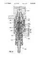
- FIG. 3ais a cross-sectional view of the card-edge part of FIG. 2a;
- FIG. 3bis a cross-sectional view of the backplane part of FIG. 2b;
- FIG. 4is a cross-sectional view of the alignment assembly parts shown in FIGS. 3a and 3b when mated;
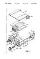
- FIG. 5is an exploded perspective view of an optical module incorporating the card-edge part of the alignment assembly of FIG. 1;
- FIG. 6ais a perspective view of the optical module of FIG. 5 with associated backplane parts
- FIG. 6bis a perspective view of the optical module and backplane parts of FIGS. 6a shown mated;
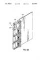
- FIG. 7is a cross-sectional view of a crd-edge part of an alignment assembly according to another embodiment of the invention.
- FIG. 8is a cross-sectional view of the alignment assembly parts of FIG. 3b and FIG. 7 when fully assembled and mated;
- FIg. 9is a perspective view of an insert for installation in the backplane part shown in FIG. 2b.
- FIG. 10is a perspective view of the insert of FIG. 9 shown assembled with an alignment sleeve carried of the card edge part of FIG. 2a and a socket member and spring clip of the backplane part of FIG. 2b.
- FIG. 1is a perspective view of an assembly 100 for axially aligning two ferrules.
- the assembly 100comprises a card-edge part 200 and a backplane part 300.
- FIG. 2ais an exploded perspective view and FIG. 3a is a cross-sectional view of the card-edge part 200.
- FIG. 2bis an exploded perspective view and FIG. 3b is a cross-sectional view of the backplane part 300.
- the card-edge part 200comprises a first housing 210 for mounting to a rear edge of a circuit card or circuit module.
- the first housing 210comprises a mounting block 220 having a recess 222 in an end surface 224.
- the recess 222is terminated in a device mounting surface 226 to which an optoelectronic device 228 is mounted.
- the first housing 210further comprises a ferrule retainer 230 having a central passage 232.
- the passage 232has a wide portion 233 adjacent an outer end 234 of the ferrule retainer 230, a narrow portion 235 adjacent an inner end 236 of the ferrule retainer 230 and a central portion 237 of intermediate width between the wide and narrow portions 233, 235.
- the ferrule retainer 230also has three radially extending notches 238 at its outer end 234.
- a first precision ferrule 240is received in the central portion 237 of the passage 232 and rigidly retained with a suitable adhesive such as epoxy.
- the ferrule 240has a leading end 242 which protrudes from the outer end 234 of the ferrule retainer 230 and a central passage 243 which receives and retains an optical fiber stub 246.
- the optical fiber stub 246has an outer end 247 which is secured in the passage 243 and polished flush with the leading end 242 of the ferrule 240, and an inner end 248 which protrudes from the ferrule 240 along the narrow portion 235 of the ferrule retainer 230.
- the first housing 210further comprises an alignment tube 250.
- the ferrule retainer 230is inserted into the alignment tube 250 with the inner end 236 of the ferrule retainer 230 protruding beyond an inner end surface 256 of the alignment tube 250, and the protruding end 236 of the ferrule retainer 230 is inserted into the recess 222 until the inner end surface 256 of the alignment tube 250 bears against the end surface 224 of the mounting block 220.
- the inner end surface 256 of the alignment tube 250is then moved laterally on the end surface 224 of the mounting block 220 and the ferrule retainer 230 is moved axially within the alignment tube 250 to optimize optical coupling between the optoelectronic device 228 and the fiber stub 246.
- the alignment tube 250is secured in its optimal position on the end surface 224 of the mounting block 220 and the ferrule retainer 230 is secured in its optimal position in the alignment tube 250 by laser welding.
- the card-edge part 200further comprises a bracket 260 comprising a bracket body 262 having a screw-threaded tubular projection 264.
- a passage 266extends through the body 262 and projection 264, and an outer end 268 of the projection 264 has three radially extending notches 269.
- the ferrule retainer 230fits into the passage 266 of the bracket 260 with the outer end 234 of the ferrule retainer 230 flush with the outer end 268 of the projection 264 and the radial notches 238 of the ferrule retainer 230 radially aligned with the radial notches 269 of the projection 264.
- the bracket 260is mounted to the rear edge of the circuit card or module with the ferrule retainer 230 in place.
- the card-edge part 200further comprises an alignment sleeve carrier 270 having a passage 271 which extends axially through the alignment sleeve carrier 270.
- the passage 271has an internal annular shoulder 272 at a leading end 273 of the alignment sleeve carrier 270.
- the leading end 273 of the alignment sleeve carrier 270is champfered and has a pair of ramp surfaces 274 and a pair of laterally extending grooves 275, each groove 275 adjacent a respective one of the ramp surfaces 274.
- the card-edge part 200further comprises a split alignment sleeve 280 having an inner diameter which is slightly less than the outer diameter of the ferrule 240 and an outer diameter which is slightly less than the inner diameter of the alignment sleeve carrier 270.
- the alignment sleeve 280is inserted into the passage 271 from a trailing end 276 of the alignment sleeve carrier 270, and a retaining ring 277 of the alignment sleeve carrier 270 is friction fit into the passage 271 to define another shoulder which, together with the shoulder 272, retains the alignment sleeve 280 in the passage 271.
- the leading end 242 of the first ferrule 240is inserted into the passage 271 at the trailing end 276 of the alignment sleeve carrier 270 where it picks up and enters the alignment sleeve 280, the alignment sleeve 280 expanding resiliently and radially to receive the ferrule 240.
- the alignment sleeve carrier 270also has a radially notched outer flange 278 spaced from the trailing end 276 to define an external shoulder.
- the trailing end 276 of the alignment sleeve carrier 270fits loosely into the wide portion 233 of the passage 232 of the ferrule retainer 230, and the flange 278 bears against the outer ends 234, 268 of the ferrule retainer 230 and the tubular projection 264 of the bracket 260.
- the notched flange 278 of the alignment sleeve carrier 270mates with the complementary notches 238, 269 of the ferrule retainer 230 and the projection 264 of the bracket 260 to rotationally key the alignment sleeve carrier 270 to the first housing 210.
- the card-edge part 200further comprises first securing means in the form of a retaining nut 290 which threads onto the complementary screw threaded tubular projection 264 of the bracket 260 to secure the alignment sleeve carrier 270 to the first housing 210.
- the nut 290bears against the outer end collar 268 of the tubular projection 264 when the nut 290 is fully tightened onto the tubular projection 264 and captures the flange 278 of the alignment sleeve carrier 270 to retain the alignment sleeve carrier 270 on the first housing 210.
- the radial notches 238, 269 of the ferrule retainer 230 and the tubular projection 264are deeper than the thickness of the flange 278 and the trailing end 276 of the alignment sleeve carrier 270 fits loosely in the wide portion 233 of the passage 232 of the ferrule retainer 230 so that the nut 280 permits limited lateral, axial and angular movement of the alignment sleeve carrier 270 on the first housing 210.
- the backplane part 300comprises a second housing 310 having a cavity 312 defined by a pair of axially spaced walls 314, 315.
- the cavity 312has a lateral opening 316.
- a passage 318extends axially through the second housing 310 passing through each of the walls 314, 315.
- the backplane part 300further comprises a socket member 320 having a through passage 321.
- the passage 321is internally champfered at a leading end 322 and has an internal shoulder 323 between its leading end 322 and a trailing end 324.
- the socket member 320has a pair of laterally extending slots 325 which extend through opposite sides 326 of the socket member 320 to the passage 321 adjacent its leading end 322.
- the socket member 320also has a male bayonet fitting 327 adjacent its trailing end 324.
- the socket member 320fits loosely into the passage 318 of the second housing 310.
- the backplane part 300further comprises second securing means comprising spring means in the form of a spring clip 330.
- the spring clip 330comprises a spring member having a coiled central portion 332 and ends protruding from the coiled portion 332 to define a pair of spring elements or legs 334.
- the socket member 320is inserted into the passage 318 of the second housing 310 and the spring clip 330 is inserted into the lateral opening 316 of the second housing 310 so that the legs 334 fit into the slots 325 to capture the socket member 320 in the passage 318 of the second housing 310.
- the legs 334protrude laterally into the passage 321 of the socket member 320 from the slots 325.
- the backplane part 300further comprises a spring clip retainer in the form of a pin 340 which is friction fit into aligned holes 342 in the axially spaced walls 314, 315 to extend axially between the walls 314, 315 and to pass through the coiled portion 332 capturing the spring clip 330 between the axially spaced walls 314, 315.
- the pin 340permits limited axial, angular and lateral movement of the spring clip 330 within the cavity 312, thereby permitting limited axial, angular and lateral movement of the socket member 320 within the passage 318 of the second housing 310.
- the axially spaced walls 314, 315define forward and rearward limits respectively of the axial movement of the spring clip 330 within the cavity 312.
- a ferrule carrier 400is shown mounted to the backplane part 300.
- the ferrule carrier 400comprises a barrel 410 having a female bayonet fitting 412 and a through passage 414.
- a backshell 420slides within the passage 414 and is mechanically coupled to the barrel 410 by a helical spring 430.
- the backshell 420is retained within the passage by a C-clip 426.
- the backshell 420has a through passage 422 within which a second precision ferrule 440 is secured. Like the first ferrule 240, the second ferrule 440 has a central passage 442 within which an optical fiber 450 is secured. The optical fiber 450 is polished flush with a leading end 44 of the ferrule 440.
- the ferrule carrier 400is mounted to the backplane part 300 by inserting the ferrule 440 into the passage 321 of the socket member 320 at the trailing end 24 of the passage 321, and mating the female bayonet fitting 412 of the barrel 410 with the male bayonet fitting 27 of the socket member 320.
- a leading end 424 of the backshell 420bears against the internal shoulder 323 of the socket member 320, and the spring 430 compresses to permit the second ferrule 440 to protrude beyond the barrel 410 into the passage 321 of the socket member 320.
- FIG. 4is a cross-sectional view of the card-edge part 200 and the backplane part 300 when mated.
- the card-edge part 200is mounted at a rear edge of a circuit card or module and the backplane part 300 is mounted to a backplane of an equipment rack so that alignment sleeve carrier 270 of the card-edge part 200 enters the socket member 320 of the backplane part 300 as the circuit card is fully inserted into card guides of the equipment rack.
- the champfered ends 273, 322 of the alignment sleeve carrier 270 and the passage 321 of the socket member 320facilitate entry of the alignment sleeve carrier 270 into the socket member 320 when the card-edge part 200 and backplane part 300 are slightly misaligned.
- the alignment sleeve carrier 270is capable of limited angular and lateral movement on the first housing 210 and the socket member 320 is capable of limited angular and lateral movement on the second housing 310 to facilitate entry of the alignment sleeve carrier 270 into the socket member 320.
- the ramp surfaces 274engage the legs 334 of the spring clip 330 and urge the spring clip 330 and socket member 320 rearward in the cavity 312 until the spring clip 330 engages the rearmost wall 315 at its rearward limit of axial movement.
- the rotational keying of the alignment sleeve carrier 270 to the ferrule retainer 230 by means of the notches 238 and flange 278prevents rotation of the alignment sleeve carrier 270 when it is secured to the first housing 210 to ensure proper engagement of the ramp surfaces 274 with the spring clip legs 334.)
- the flange 278 of the alignment sleeve carrier 270is urged rearward against the outer end 234 of the ferrule retainer 230.
- the leading end 444 of the second ferrule 440enters the passage 271 of the alignment sleeve carrier 270 and picks up the leading end of the alignment sleeve 280.
- the helical spring 430compresses to permit the alignment sleeve carrier 270 to enter the socket member 320 far enough for latching as described above.
- the alignment sleeve 280expands resiliently and radially to permit entry of the second ferrule 440 and exerts a radially inward force to hold the first and second ferrules 240, 440 in axial alignment.
- the helical spring 430keeps the second ferrule 440 butted against the first ferrule 240. Limited angular and axial movement of the alignment sleeve carrier 270 on the first housing 210 and of the socket member 320 on the second housing 310 facilitates alignment of the ferrules 240, 440 in the alignment sleeve 280.
- the legs 334 of the spring clip 330drop into the grooves 275 of the alignment sleeve carrier 270 to latch the alignment sleeve carrier 270 into the socket member 320, they pull the alignment sleeve carrier 270 forward, disengaging the flange 278 from the outer end 234 of the ferrule retainer 230.
- the minimum distance between the rearmost wall 315 of the cavity 312 and the outer end 234 of the ferrule retainer 230 when the card-edge part 200 is mated to the backplane part 300is made less than the distance between the flange 278 and the grooves 275 of the alignment sleeve carrier 270 so that the spring clip 330 can move away from the rearmost wall 315 of the cavity 312 (i.e.
- the card-edge part 200can be unmated from the backplane part 300 by pulling the card-edge part with sufficient force to disengage the legs 334 of the spring clip 330 from the grooves 275 of the alignment sleeve carrier 270.
- the depth of the grooves 275is made less than radius of the circular cross-section of the legs 334 to ensure that the legs 334 will disengage from the grooves 275 when pulled with sufficient force.
- FIG. 5is an exploded perspective view of a card-edge part 200' having a first housing 210, adapted to carry two optoelectronic devices 228 and associated electronic circuitry.
- FIG. 6ais a perspective view of the cardedge part 200, with associated backplane parts 300', and FIG. 6b is a perspective view of the card-edge part 200' and backplane parts when mated.
- the first housing 210'further comprises a module carrier comprising a base 212 and a lid 213 which fastens to the base 212 to enclose a printed circuit board 214.
- the base 212carries two mounting blocks 220 at a 1eading edge 215.
- Two alignment sleeve carriers 270are secured to the base 212, each via a respective one of the mounting blocks 220.
- Each alignment sleeve carrier 270is mounted for limited axial, angular and lateral movement via retaining nut 290 and a threaded tubular projection 264 as in the alignment assembly 100.
- An electrical card-edge connector part 500is also mounted on the base 212, and the electrical card-edge connector part 500 and optoelectronic devices 228 carried by the mounting blocks 220 are electrically connected to the circuit board 214 by terminal pins 216.
- the base 212further comprises two guide formations in the form of axially extending ridges 217 at side edges of the base 212.
- the lid 213also includes a latch release in the form of a lever 218 pivotably mounted at a rear edge of the carrier 212.
- the second housing 310' of the associated backplane partsfurther comprises a two part frame 350.
- Two socket members 320are secured to a rearward part 352 of the frame 350, each mounted for limited axial, angular and lateral movement as in the alignment assembly 100.
- a forward part 354 of the frame 350carries an electrical card-edge connector part 502 which is complementary to the electrical card-edge connector part 500 on the first housing 210'.
- the forward part 354 of the frame 350comprises two guide formations in the form of guide rails 356 extending axially along the forward part 354, each quide rail 356 havinq a qroove 357 whioh is oomplementary to a respective one of the ridqes 217 ot the tirst housinq 210'.
- the forward part 354also has two openings 358. The forward part 354 is secured to the rearward part 352 with the openings 358 aligned with the socket members 320.
- the connector parts 200', 300'are mated by sliding the ridges 217 along the complementary grooves 357 of the guide rails 356.
- the ridges 217 and guide rails 356guide the housings 210', 310' together so that the alignment sleeve carriers 270 enter respective socket members 320 through the openings 358 to align two pairs of first and second ferrules 240, 440 in a single mating operation, and the electrical card edge connector parts 500, 502 mate to complete an electrical connection in the same mating Operation.
- FIB. 6bshows the connector 200', 300', when mated.
- the connector parts 2---', 400'can be unlatched by pivoting one end of the lever 218 away from the rear edge of the tirst housinq 210' to urge the other end of the lever 218 against a forward end of one of the guide rails 356 and thereby pull the first housing 210' and its attached alignment sleeve carriers 270 away from the frame 350 and its attached socket members 320.
- FIG. 7is a cross-sectional view of a card-edge part 600 of another ferrule alignment assembly.
- the card-edge part 600is adapted to receive a ferrule 440 of a ferrule carrier 400 as described above.
- the card-edge part 600comprises a first housing 610 which has a through passage 612 for receiving the ferrule 440 of the ferrule carrier 400.
- the first housing 610further comprises a male bayonet fitting 614 for mating with a female bayonet fitting 412 of the ferrule carrier 400 to secure the ferrule carrier 400 to the first housing 610 with the ferrule 440 extending into the passage 612.
- the card-edge part 600further comprises an alignment sleeve carrier 670 which is integral with the first housing 610.
- An alignment sleeve 680is retained in a through passage 671 of the alignment sleeve carrier 670 in the manner described above for the alignment sleeve carrier 270 and alignment sleeve 280 of the ferrule alignment assembly 100.
- the alignment sleeve carrier 670has a champfered leading end 673 bearing ramp surfaces 674 and grooves 675 similar to the corresponding structures 273, 274, 275 of the alignment sleeve carrier 270.
- ferrule carriers 400are mated with the card-edge part 600 and a backplane part 300 as described above with reference to FIG. 2b.
- the backplane and card-edge parts 300, 600are brought together so that the alignment sleeve carrier 670 enters and latches into the socket member 320.
- the alignment processis as described in detail above for the alignment assembly 100 except that the alignment sleeve carrier 670 is rigid with respect to the first housing 610, but both ferrules 440 are capable of limited axial, angular and lateral movement within their respective ferrule carriers 400.
- the socket member 320moves on the second housing 310 as necessary to accept the rigidly held alignment sleeve carrier 670, and the alignment sleeve 280 moves within the rigid alignment sleeve carrier 670 and both ferrules 440 move within their respective carriers 400 so that the alignment sleeve 280 accepts and aligns the ferrules 440.
- FIG. 8is a cross-sectional view of the backplane part 300, ferrule carriers 400 and card-edge part 600 when fully assembled to complete an optical connection.
- the alignment sleeve carrier 670could also be movably mounted to the first housing 610 to further facilitate alignment and reduce residual stresses.
- the alignment sleeve carrier 670could be secured to the first housing 610 by a retaining nut as in the assembly 100.
- FIG. 9is a perspective view of an insert 700 which can be supplied as part of the second housing 310 of the backplane part 300 to facilitate unmating of the card-edge part 200, 600 from the backplane part 300.
- the insert 700is installed in the cavity 312 of the second housing 310, and has a passage 710 which is within the passage 318 of the second housing 310.
- the passage 710is sized to receive the socket member 320 and the alignment sleeve carrier 270, 670.
- the insert 700has laterally extending through slots 720 which align with the slots 325 of the socket member 320 when the socket member 320 is in the passage 710, so that the legs 334 of the spring clip 330 pass through the slots 325, 720 of both the insert 700 and the socket member 320.
- the insertis free to move axially within the passage 318 of the second housing 310 together with the socket member 320, but its forward movement is limited by the forward wall 314 of the cavity 312, and its rearward movement is limited by the spring clip 330 when the spring clip engages the rear wall 315 of the cavity 312.
- the insert 700has four ramp formations 730 which engaqe the legs 334 of the spring clip 330 when the card-edge part 200, 600 is pulled away trom the haokplane part 300 to unmate the parts 200, 300, 600.
- the ramp formations 730spread the legs 334 of the spring clip 330 to disengage the legs 334 from the grooves 275, 675 of the alignment sleeve carrier 270, 670, thereby facilitating unmating of the parts 200, 300, 600. (See FIG. 9 which shows the alignment sleeve carrier 270, the socket member 320, the spring clip 330 and the insert assembled together.)
Landscapes
- Physics & Mathematics (AREA)
- General Physics & Mathematics (AREA)
- Optics & Photonics (AREA)
- Mechanical Coupling Of Light Guides (AREA)
- Optical Couplings Of Light Guides (AREA)
Abstract
Description
Claims (20)
Priority Applications (2)
| Application Number | Priority Date | Filing Date | Title |
|---|---|---|---|
| US07/838,170US5151961A (en) | 1992-02-20 | 1992-02-20 | Ferrule alignment assembly for blind mating optical fiber connector |
| JP5055125AJPH0752250B2 (en) | 1992-02-20 | 1993-02-19 | Blind splicing fiber optic connector |
Applications Claiming Priority (1)
| Application Number | Priority Date | Filing Date | Title |
|---|---|---|---|
| US07/838,170US5151961A (en) | 1992-02-20 | 1992-02-20 | Ferrule alignment assembly for blind mating optical fiber connector |
Publications (1)
| Publication Number | Publication Date |
|---|---|
| US5151961Atrue US5151961A (en) | 1992-09-29 |
Family
ID=25276453
Family Applications (1)
| Application Number | Title | Priority Date | Filing Date |
|---|---|---|---|
| US07/838,170Expired - Fee RelatedUS5151961A (en) | 1992-02-20 | 1992-02-20 | Ferrule alignment assembly for blind mating optical fiber connector |
Country Status (2)
| Country | Link |
|---|---|
| US (1) | US5151961A (en) |
| JP (1) | JPH0752250B2 (en) |
Cited By (45)
| Publication number | Priority date | Publication date | Assignee | Title |
|---|---|---|---|---|
| US5280551A (en)* | 1992-12-23 | 1994-01-18 | At&T Bell Laboratories | Backplane optical spine |
| US5530783A (en)* | 1994-08-31 | 1996-06-25 | Berg Technology, Inc. | Backplane optical fiber connector for engaging boards of different thicknesses and method of use |
| US5563971A (en)* | 1995-04-28 | 1996-10-08 | The Whitaker Corporation | Floating bottleneck for multiple position fiber optic receptacle |
| US5577145A (en)* | 1992-11-30 | 1996-11-19 | Hewlett-Packard Company | Optical connector including split sleeve secured in expanded state |
| US5594826A (en)* | 1995-07-19 | 1997-01-14 | Welch Allyn, Inc. | Interchangeable nose adapter |
| US5729644A (en)* | 1996-02-26 | 1998-03-17 | Alcoa Fujikura Limited | Receptacle for multi-fiber connector |
| US5751875A (en)* | 1996-10-04 | 1998-05-12 | The Whitaker Corporation | Optical fiber ferrule |
| US5754721A (en)* | 1996-09-05 | 1998-05-19 | E-Tek Dynamics, Inc. | Fiberoptic connector |
| US5802228A (en)* | 1996-12-16 | 1998-09-01 | Lucent Technologies Inc. | Optical package with removable fiber termination |
| US5896485A (en)* | 1996-03-22 | 1999-04-20 | Northern Telecom Limited | Equipment backplane for providing mechanical support and a communications path between equipment modules |
| EP0926521A1 (en)* | 1997-12-19 | 1999-06-30 | The Whitaker Corporation | Simplified fiber optic receptacle |
| US6113283A (en)* | 1997-05-15 | 2000-09-05 | Telefonaktiebolaget Lm Ericsson | Optical capsule having a connector |
| US6305848B1 (en)* | 2000-06-19 | 2001-10-23 | Corona Optical Systems, Inc. | High density optoelectronic transceiver module |
| US20020168153A1 (en)* | 2001-05-09 | 2002-11-14 | Naoyuki Yamabayashi | Fiber stub, optical module, optical transmitter, and optical communication system |
| US6626582B2 (en)* | 2000-02-17 | 2003-09-30 | Cogent Light Technologies, Inc. | Snap-on connector system for coupling light from an illuminator to a fiber optic |
| US20030185525A1 (en)* | 2002-03-27 | 2003-10-02 | Agilent Technologies, Inc. | Module apparatus and method of alignment |
| EP1018660A3 (en)* | 1999-01-07 | 2003-12-17 | Delphi Technologies, Inc. | Coupling device for coupling an optical fibre to an optoelectronic module |
| US6712526B1 (en)* | 2000-07-13 | 2004-03-30 | Corning Cable Systems Llc | Angled physical contact ferrule and associated method and apparatus for fabricating same |
| US6799902B2 (en) | 2000-12-26 | 2004-10-05 | Emcore Corporation | Optoelectronic mounting structure |
| US20040252950A1 (en)* | 2003-05-09 | 2004-12-16 | Molex Incorporated | Method for producing an assembly comprising a waveguide section and an optical component |
| US20050013559A1 (en)* | 2003-07-16 | 2005-01-20 | Agilent Technologies, Inc. | Interface adaptor |
| US6863444B2 (en) | 2000-12-26 | 2005-03-08 | Emcore Corporation | Housing and mounting structure |
| US6863453B2 (en) | 2003-01-28 | 2005-03-08 | Emcore Corporation | Method and apparatus for parallel optical transceiver module assembly |
| US6867377B2 (en) | 2000-12-26 | 2005-03-15 | Emcore Corporation | Apparatus and method of using flexible printed circuit board in optical transceiver device |
| US20050089281A1 (en)* | 2003-06-20 | 2005-04-28 | Chia-Hung Chiu | Optical transceiver module |
| US6905260B2 (en) | 2000-12-26 | 2005-06-14 | Emcore Corporation | Method and apparatus for coupling optical elements to optoelectronic devices for manufacturing optical transceiver modules |
| US20050213897A1 (en)* | 2004-03-29 | 2005-09-29 | Palmer Jeffrey D | Field-installable fusion spliced fiber optic connector kits and methods therefor |
| US20050210668A1 (en)* | 2004-03-29 | 2005-09-29 | Palmer Jeffrey D | Tools and methods for field-installable fusion spliced fiber optic connectors |
| US7021836B2 (en) | 2000-12-26 | 2006-04-04 | Emcore Corporation | Attenuator and conditioner |
| US20060093281A1 (en)* | 2004-10-28 | 2006-05-04 | Kesler James R | Fiber optic connector |
| US20060115219A1 (en)* | 2004-11-29 | 2006-06-01 | Mudd Ronald L | Optical fiber connector |
| EP1775612A2 (en) | 2005-10-10 | 2007-04-18 | Phoenix Contact GmbH & Co. KG | Optical Cable Connecting Device |
| US20080008429A1 (en)* | 2006-07-05 | 2008-01-10 | Futoshi Endou | Receptacle type optical apparatus |
| US20080013894A1 (en)* | 2006-06-28 | 2008-01-17 | Fujitsu Limited | Optical receptacle and sleeve |
| US20080253719A1 (en)* | 2007-04-13 | 2008-10-16 | Kachmar Wayne M | Field terminatable fiber optic connector assembly |
| US20090269011A1 (en)* | 2007-11-30 | 2009-10-29 | Jarrod Scadden | Hybrid fiber/copper connector system and method |
| US7676134B2 (en) | 2007-04-13 | 2010-03-09 | Adc Telecommunications, Inc. | Field termination kit |
| US20110038592A1 (en)* | 2009-08-13 | 2011-02-17 | Ronald Mudd | Optical fiber adapter |
| US8636425B2 (en) | 2011-03-15 | 2014-01-28 | Adc Telecommunications, Inc. | Fiber optic connector |
| WO2014182352A1 (en)* | 2013-05-09 | 2014-11-13 | Cotsworks, Llc | Separable locking fiber optic connector |
| US9176285B2 (en) | 2012-05-03 | 2015-11-03 | Adc Telecommunications, Inc. | Fiber optic connector |
| US9268102B2 (en) | 2012-02-07 | 2016-02-23 | Tyco Electronics Raychem Bvba | Cable termination assembly and method for connectors |
| US20160356968A1 (en)* | 2009-09-03 | 2016-12-08 | Tyco Electronics Raychem Bvba | Positioning means for a fibre optic connector assembly, a fibre optic connector assembly and fibre termination unit |
| US10690860B2 (en)* | 2017-10-20 | 2020-06-23 | Kow-Je Ling | Optical fiber connector and assembling structure thereof |
| US11105984B2 (en)* | 2019-10-11 | 2021-08-31 | Ii-Vi Delaware, Inc. | Retention device for optoelectronic connections |
Families Citing this family (1)
| Publication number | Priority date | Publication date | Assignee | Title |
|---|---|---|---|---|
| US7090509B1 (en)* | 1999-06-11 | 2006-08-15 | Stratos International, Inc. | Multi-port pluggable transceiver (MPPT) with multiple LC duplex optical receptacles |
Citations (7)
| Publication number | Priority date | Publication date | Assignee | Title |
|---|---|---|---|---|
| US4354731A (en)* | 1979-10-02 | 1982-10-19 | E. I. Du Pont De Nemours And Company | Self-aligning optical fiber connector |
| US4541685A (en)* | 1983-03-07 | 1985-09-17 | At&T Bell Laboratories | Optical connector sleeve |
| US4690494A (en)* | 1984-05-07 | 1987-09-01 | Daiichi Denshi Kogyo Kabushiki Kaisha | Ferrule holding device for optical fiber connector |
| US4699458A (en)* | 1983-03-10 | 1987-10-13 | Allied Corporation | Fiber optic connector |
| US4726647A (en)* | 1985-03-19 | 1988-02-23 | Sumitomo Electric Industries, Ltd. | Optical connector |
| US4895425A (en)* | 1988-02-26 | 1990-01-23 | Nippon Telegraph And Telephone Corporation | Plug-in optical fiber connector |
| US4923272A (en)* | 1988-10-03 | 1990-05-08 | Joseph Cuda | Fiber optic connector |
- 1992
- 1992-02-20USUS07/838,170patent/US5151961A/ennot_activeExpired - Fee Related
- 1993
- 1993-02-19JPJP5055125Apatent/JPH0752250B2/ennot_activeExpired - Lifetime
Patent Citations (7)
| Publication number | Priority date | Publication date | Assignee | Title |
|---|---|---|---|---|
| US4354731A (en)* | 1979-10-02 | 1982-10-19 | E. I. Du Pont De Nemours And Company | Self-aligning optical fiber connector |
| US4541685A (en)* | 1983-03-07 | 1985-09-17 | At&T Bell Laboratories | Optical connector sleeve |
| US4699458A (en)* | 1983-03-10 | 1987-10-13 | Allied Corporation | Fiber optic connector |
| US4690494A (en)* | 1984-05-07 | 1987-09-01 | Daiichi Denshi Kogyo Kabushiki Kaisha | Ferrule holding device for optical fiber connector |
| US4726647A (en)* | 1985-03-19 | 1988-02-23 | Sumitomo Electric Industries, Ltd. | Optical connector |
| US4895425A (en)* | 1988-02-26 | 1990-01-23 | Nippon Telegraph And Telephone Corporation | Plug-in optical fiber connector |
| US4923272A (en)* | 1988-10-03 | 1990-05-08 | Joseph Cuda | Fiber optic connector |
Non-Patent Citations (4)
| Title |
|---|
| "A High Fiber Density Optical Connector for use in Electronic Packaging Systems", SPIE vol. 752, Digital Optical Computing (1987), pp. 217-221. |
| "Circuit Board-to Backplane Connector for Fiber-to-the -Home Applications", FOC/LAN '88, 12th Int'l Fiber Optic Communications and Local Area Networks Exposition, Feb. 12-16, 1988, pp. 255-257. |
| A High Fiber Density Optical Connector for use in Electronic Packaging Systems , SPIE vol. 752, Digital Optical Computing (1987), pp. 217 221.* |
| Circuit Board to Backplane Connector for Fiber to the Home Applications , FOC/LAN 88, 12th Int l Fiber Optic Communications and Local Area Networks Exposition, Feb. 12 16, 1988, pp. 255 257.* |
Cited By (84)
| Publication number | Priority date | Publication date | Assignee | Title |
|---|---|---|---|---|
| US5577145A (en)* | 1992-11-30 | 1996-11-19 | Hewlett-Packard Company | Optical connector including split sleeve secured in expanded state |
| US5280551A (en)* | 1992-12-23 | 1994-01-18 | At&T Bell Laboratories | Backplane optical spine |
| US5530783A (en)* | 1994-08-31 | 1996-06-25 | Berg Technology, Inc. | Backplane optical fiber connector for engaging boards of different thicknesses and method of use |
| US5563971A (en)* | 1995-04-28 | 1996-10-08 | The Whitaker Corporation | Floating bottleneck for multiple position fiber optic receptacle |
| US5594826A (en)* | 1995-07-19 | 1997-01-14 | Welch Allyn, Inc. | Interchangeable nose adapter |
| US5729644A (en)* | 1996-02-26 | 1998-03-17 | Alcoa Fujikura Limited | Receptacle for multi-fiber connector |
| US5896485A (en)* | 1996-03-22 | 1999-04-20 | Northern Telecom Limited | Equipment backplane for providing mechanical support and a communications path between equipment modules |
| US5754721A (en)* | 1996-09-05 | 1998-05-19 | E-Tek Dynamics, Inc. | Fiberoptic connector |
| US5751875A (en)* | 1996-10-04 | 1998-05-12 | The Whitaker Corporation | Optical fiber ferrule |
| US5802228A (en)* | 1996-12-16 | 1998-09-01 | Lucent Technologies Inc. | Optical package with removable fiber termination |
| US6113283A (en)* | 1997-05-15 | 2000-09-05 | Telefonaktiebolaget Lm Ericsson | Optical capsule having a connector |
| EP0926521A1 (en)* | 1997-12-19 | 1999-06-30 | The Whitaker Corporation | Simplified fiber optic receptacle |
| EP1018660A3 (en)* | 1999-01-07 | 2003-12-17 | Delphi Technologies, Inc. | Coupling device for coupling an optical fibre to an optoelectronic module |
| US6626582B2 (en)* | 2000-02-17 | 2003-09-30 | Cogent Light Technologies, Inc. | Snap-on connector system for coupling light from an illuminator to a fiber optic |
| US6305848B1 (en)* | 2000-06-19 | 2001-10-23 | Corona Optical Systems, Inc. | High density optoelectronic transceiver module |
| US6712526B1 (en)* | 2000-07-13 | 2004-03-30 | Corning Cable Systems Llc | Angled physical contact ferrule and associated method and apparatus for fabricating same |
| US6905260B2 (en) | 2000-12-26 | 2005-06-14 | Emcore Corporation | Method and apparatus for coupling optical elements to optoelectronic devices for manufacturing optical transceiver modules |
| US7021836B2 (en) | 2000-12-26 | 2006-04-04 | Emcore Corporation | Attenuator and conditioner |
| US6799902B2 (en) | 2000-12-26 | 2004-10-05 | Emcore Corporation | Optoelectronic mounting structure |
| US6863444B2 (en) | 2000-12-26 | 2005-03-08 | Emcore Corporation | Housing and mounting structure |
| US6867377B2 (en) | 2000-12-26 | 2005-03-15 | Emcore Corporation | Apparatus and method of using flexible printed circuit board in optical transceiver device |
| US7059780B2 (en)* | 2001-05-09 | 2006-06-13 | Sumitomo Electric Industries, Ltd. | Fiber stub, optical module, optical transmitter, and optical communication system |
| US20020168153A1 (en)* | 2001-05-09 | 2002-11-14 | Naoyuki Yamabayashi | Fiber stub, optical module, optical transmitter, and optical communication system |
| US20030185525A1 (en)* | 2002-03-27 | 2003-10-02 | Agilent Technologies, Inc. | Module apparatus and method of alignment |
| US6929407B2 (en)* | 2002-03-27 | 2005-08-16 | Agilent Technologies, Inc. | Module apparatus and method of alignment |
| US6863453B2 (en) | 2003-01-28 | 2005-03-08 | Emcore Corporation | Method and apparatus for parallel optical transceiver module assembly |
| US20040252950A1 (en)* | 2003-05-09 | 2004-12-16 | Molex Incorporated | Method for producing an assembly comprising a waveguide section and an optical component |
| US20050089281A1 (en)* | 2003-06-20 | 2005-04-28 | Chia-Hung Chiu | Optical transceiver module |
| US7178991B2 (en)* | 2003-06-20 | 2007-02-20 | Industrial Technology Research Institute | Optical transceiver module |
| US20050013559A1 (en)* | 2003-07-16 | 2005-01-20 | Agilent Technologies, Inc. | Interface adaptor |
| US20050210668A1 (en)* | 2004-03-29 | 2005-09-29 | Palmer Jeffrey D | Tools and methods for field-installable fusion spliced fiber optic connectors |
| US20050213897A1 (en)* | 2004-03-29 | 2005-09-29 | Palmer Jeffrey D | Field-installable fusion spliced fiber optic connector kits and methods therefor |
| US20070196054A1 (en)* | 2004-03-29 | 2007-08-23 | Palmer Jeffrey D | Field-installable fusion spliced fiber optic connector kits and methods therefor |
| US7594764B2 (en) | 2004-03-29 | 2009-09-29 | Corning Cable Systems Llc | Field-installable fusion spliced fiber optic connector kits and methods therefor |
| US20060093281A1 (en)* | 2004-10-28 | 2006-05-04 | Kesler James R | Fiber optic connector |
| US7128475B2 (en)* | 2004-10-28 | 2006-10-31 | Schweitzer Engineering Laboratories, Inc. | Fiber optic connector |
| US20060115219A1 (en)* | 2004-11-29 | 2006-06-01 | Mudd Ronald L | Optical fiber connector |
| EP1775612A2 (en) | 2005-10-10 | 2007-04-18 | Phoenix Contact GmbH & Co. KG | Optical Cable Connecting Device |
| CN1960060B (en)* | 2005-10-10 | 2010-09-29 | 菲尼克斯电气公司 | Connecting device |
| EP1775612A3 (en)* | 2005-10-10 | 2008-11-19 | Phoenix Contact GmbH & Co. KG | Optical Cable Connecting Device |
| US20080013894A1 (en)* | 2006-06-28 | 2008-01-17 | Fujitsu Limited | Optical receptacle and sleeve |
| US20080008429A1 (en)* | 2006-07-05 | 2008-01-10 | Futoshi Endou | Receptacle type optical apparatus |
| US7534050B2 (en)* | 2007-04-13 | 2009-05-19 | Adc Telecommunications, Inc. | Field terminatable fiber optic connector assembly |
| US9389372B2 (en)* | 2007-04-13 | 2016-07-12 | Commscope Technologies Llc | Fiber optic connector with fiber take-up region |
| US10175429B2 (en)* | 2007-04-13 | 2019-01-08 | Commscope Technologies Llc | Fiber optic connector with fiber take-up region |
| US7676134B2 (en) | 2007-04-13 | 2010-03-09 | Adc Telecommunications, Inc. | Field termination kit |
| US7766556B2 (en)* | 2007-04-13 | 2010-08-03 | Adc Telecommunications, Inc. | Field terminatable fiber optic connector assembly |
| US20080253719A1 (en)* | 2007-04-13 | 2008-10-16 | Kachmar Wayne M | Field terminatable fiber optic connector assembly |
| US20100272401A1 (en)* | 2007-04-13 | 2010-10-28 | Adc Telecommunications, Inc. | Field Termination Kit |
| US20190243076A1 (en)* | 2007-04-13 | 2019-08-08 | Commscope Technologies Llc | Fiber optic connector with fiber take-up region |
| US20110044590A1 (en)* | 2007-04-13 | 2011-02-24 | Adc Telecommunications, Inc. | Field terminatable fiber optic connector assembly |
| US7929819B2 (en) | 2007-04-13 | 2011-04-19 | Adc Telecommunications, Inc. | Field termination kit |
| US20170115457A1 (en)* | 2007-04-13 | 2017-04-27 | Commscope Technologies Llc | Fiber optic connector with fiber take-up region |
| US20090238522A1 (en)* | 2007-04-13 | 2009-09-24 | Adc Telecommunications, Inc. | Field terminatable fiber optic connector assembly |
| US20120328247A1 (en)* | 2007-04-13 | 2012-12-27 | Adc Telecommunications, Inc. | Field terminatable fiber optic connector assembly |
| US20150253518A1 (en)* | 2007-04-13 | 2015-09-10 | Adc Telecommunications, Inc. | Fiber optic connector with fiber take-up region |
| US8944702B2 (en)* | 2007-04-13 | 2015-02-03 | Adc Telecommunications, Inc. | Fiber optic connector with fiber take-up region |
| US8083416B2 (en) | 2007-11-30 | 2011-12-27 | Adc Telecommunications, Inc. | Hybrid fiber/copper connector system and method |
| US8678666B2 (en) | 2007-11-30 | 2014-03-25 | Adc Telecommunications, Inc. | Hybrid fiber/copper connector system and method |
| US20090269011A1 (en)* | 2007-11-30 | 2009-10-29 | Jarrod Scadden | Hybrid fiber/copper connector system and method |
| GB2484861B (en)* | 2009-08-13 | 2015-10-21 | Commscope Inc | Optical fiber adapter |
| US8290332B2 (en)* | 2009-08-13 | 2012-10-16 | Commscope, Inc. Of North Carolina | Optical fiber adapter |
| US20110038592A1 (en)* | 2009-08-13 | 2011-02-17 | Ronald Mudd | Optical fiber adapter |
| US20160356968A1 (en)* | 2009-09-03 | 2016-12-08 | Tyco Electronics Raychem Bvba | Positioning means for a fibre optic connector assembly, a fibre optic connector assembly and fibre termination unit |
| US10007070B2 (en)* | 2009-09-03 | 2018-06-26 | CommScope Connectivity Belgium BVBA | Positioning means for a fibre optic connector assembly, a fibre optic connector assembly and fibre termination unit |
| US10146011B2 (en) | 2011-03-15 | 2018-12-04 | Commscope Technologies Llc | Fiber optic connector |
| US10859771B2 (en) | 2011-03-15 | 2020-12-08 | Commscope Technologies Llc | Fiber optic connector |
| US9500813B2 (en) | 2011-03-15 | 2016-11-22 | Commscope Technologies Llc | Fiber optic connector |
| US12405430B2 (en) | 2011-03-15 | 2025-09-02 | Commscope Technologies Llc | Fiber optic connector |
| US10495822B2 (en) | 2011-03-15 | 2019-12-03 | Commscope Technologies Llc | Fiber optic connector |
| US9151904B2 (en) | 2011-03-15 | 2015-10-06 | Adc Telecommunications, Inc. | Fiber optic connector |
| US11782224B2 (en) | 2011-03-15 | 2023-10-10 | Commscope Technologies Llc | Fiber optic connector |
| US9841566B2 (en) | 2011-03-15 | 2017-12-12 | Commscope Technologies Llc | Fiber optic connector |
| US8636425B2 (en) | 2011-03-15 | 2014-01-28 | Adc Telecommunications, Inc. | Fiber optic connector |
| US9268102B2 (en) | 2012-02-07 | 2016-02-23 | Tyco Electronics Raychem Bvba | Cable termination assembly and method for connectors |
| US10036859B2 (en) | 2012-02-07 | 2018-07-31 | CommScope Connectivity Belgium BVBA | Cable termination assembly and method for connectors |
| US9625660B2 (en) | 2012-02-07 | 2017-04-18 | CommScope Connectivity Belgium BVBA | Cable termination assembly and method for connectors |
| US10371899B2 (en) | 2012-05-03 | 2019-08-06 | Commscope Technologies Llc | Fiber optic connector |
| US9638869B2 (en) | 2012-05-03 | 2017-05-02 | Commscope Technologies Llc | Fiber optic connector |
| US9176285B2 (en) | 2012-05-03 | 2015-11-03 | Adc Telecommunications, Inc. | Fiber optic connector |
| US9417407B2 (en) | 2013-05-09 | 2016-08-16 | Cotsworks, Llc | Separable locking fiber optic connector |
| WO2014182352A1 (en)* | 2013-05-09 | 2014-11-13 | Cotsworks, Llc | Separable locking fiber optic connector |
| US10690860B2 (en)* | 2017-10-20 | 2020-06-23 | Kow-Je Ling | Optical fiber connector and assembling structure thereof |
| US11105984B2 (en)* | 2019-10-11 | 2021-08-31 | Ii-Vi Delaware, Inc. | Retention device for optoelectronic connections |
Also Published As
| Publication number | Publication date |
|---|---|
| JPH0752250B2 (en) | 1995-06-05 |
| JPH0611627A (en) | 1994-01-21 |
Similar Documents
| Publication | Publication Date | Title |
|---|---|---|
| US5151961A (en) | Ferrule alignment assembly for blind mating optical fiber connector | |
| US5764834A (en) | Optical fibre connector latching mechanism | |
| US6485192B1 (en) | Optical device having an integral array interface | |
| US9261653B2 (en) | Fiber optic plug assembly and optical connector system | |
| US5404416A (en) | Optical connector plug | |
| KR100308629B1 (en) | Fiber optic connector assembly | |
| US7073953B2 (en) | Modular fiber optic connection system | |
| US7261472B2 (en) | Ultra-small, form factor single fiber optical interconnect system, with push-push type insertion/withdrawal mechanism and shuttered modular connector and shuttered adapter and method for using same | |
| EP0997757B1 (en) | Cylindrical connector incorporating a rectangular optical fibre ferrule | |
| US20200284998A1 (en) | Mini duplex connector with push-pull polarity mechanism and carrier | |
| US5142597A (en) | Interconnect assembly for wall outlet | |
| US6240229B1 (en) | Connector assembly | |
| US5619604A (en) | Multi-fiber optical connector | |
| JP2771870B2 (en) | Optical connector | |
| US6579013B2 (en) | Optical fiber coupler and an optical fiber coupler incorporated within a transceiver module | |
| US20100081303A1 (en) | High density pluggable electrical and optical connector | |
| WO2006076062A2 (en) | Ultra-small, form factor single fiber optical interconnect system, with push-push type insertion/withdrawal mechanism and shuttered modular connector and shuttered adapter and method for using same | |
| JPH07159653A (en) | Plug holding device and duplex type optical connector using the same | |
| US12411298B2 (en) | Optoelectronic connections to printed circuit boards | |
| EP1606662A2 (en) | Optical fiber ferrule assembly and methods of construction | |
| EP1182477A1 (en) | Optical connector housing, optical connector using the optical connector housing and connection structure between optical connector and optical component using the optical connector housing | |
| US20050041930A1 (en) | Optic fiber connection system | |
| CN116848446A (en) | Photoelectric connector for printed circuit board |
Legal Events
| Date | Code | Title | Description |
|---|---|---|---|
| AS | Assignment | Owner name:NORTHERN TELECOM LIMITED, CANADA Free format text:ASSIGNMENT OF ASSIGNORS INTEREST.;ASSIGNOR:BELL-NORTHERN RESEARCH LTD.;REEL/FRAME:006073/0429 Effective date:19920217 Owner name:BELL-NORTHERN RESEARCH LTD., CANADA Free format text:ASSIGNMENT OF ASSIGNORS INTEREST.;ASSIGNORS:HVEZDA, JAROSLAV M.;FISHER, ROBERT W.;OLSZEWSK, EDWARD J.;AND OTHERS;REEL/FRAME:006073/0427 Effective date:19920213 | |
| FPAY | Fee payment | Year of fee payment:4 | |
| AS | Assignment | Owner name:SIECOR CORPORATION, NORTH CAROLINA Free format text:ASSIGNMENT OF ASSIGNORS INTEREST;ASSIGNOR:NORTHERN TELECOM LIMITED;REEL/FRAME:008943/0673 Effective date:19941230 | |
| AS | Assignment | Owner name:SIECOR TECHNOLOGY, INC., DELAWARE Free format text:ASSIGNMENT OF ASSIGNORS INTEREST;ASSIGNOR:SIECOR CORPORATION;REEL/FRAME:008955/0764 Effective date:19971031 | |
| FPAY | Fee payment | Year of fee payment:8 | |
| REMI | Maintenance fee reminder mailed | ||
| LAPS | Lapse for failure to pay maintenance fees | ||
| FP | Lapsed due to failure to pay maintenance fee | Effective date:20040929 | |
| STCH | Information on status: patent discontinuation | Free format text:PATENT EXPIRED DUE TO NONPAYMENT OF MAINTENANCE FEES UNDER 37 CFR 1.362 |