US5151895A - Terminal server architecture - Google Patents
Terminal server architectureDownload PDFInfo
- Publication number
- US5151895A US5151895AUS07/546,104US54610490AUS5151895AUS 5151895 AUS5151895 AUS 5151895AUS 54610490 AUS54610490 AUS 54610490AUS 5151895 AUS5151895 AUS 5151895A
- Authority
- US
- United States
- Prior art keywords
- data
- memory
- lan
- local area
- area network
- Prior art date
- Legal status (The legal status is an assumption and is not a legal conclusion. Google has not performed a legal analysis and makes no representation as to the accuracy of the status listed.)
- Expired - Lifetime
Links
Images


Classifications
- G—PHYSICS
- G06—COMPUTING OR CALCULATING; COUNTING
- G06F—ELECTRIC DIGITAL DATA PROCESSING
- G06F13/00—Interconnection of, or transfer of information or other signals between, memories, input/output devices or central processing units
- G06F13/10—Program control for peripheral devices
- G06F13/12—Program control for peripheral devices using hardware independent of the central processor, e.g. channel or peripheral processor
- G06F13/124—Program control for peripheral devices using hardware independent of the central processor, e.g. channel or peripheral processor where hardware is a sequential transfer control unit, e.g. microprocessor, peripheral processor or state-machine
- G06F13/128—Program control for peripheral devices using hardware independent of the central processor, e.g. channel or peripheral processor where hardware is a sequential transfer control unit, e.g. microprocessor, peripheral processor or state-machine for dedicated transfers to a network
- H—ELECTRICITY
- H04—ELECTRIC COMMUNICATION TECHNIQUE
- H04L—TRANSMISSION OF DIGITAL INFORMATION, e.g. TELEGRAPHIC COMMUNICATION
- H04L12/00—Data switching networks
- H04L12/28—Data switching networks characterised by path configuration, e.g. LAN [Local Area Networks] or WAN [Wide Area Networks]
- H—ELECTRICITY
- H01—ELECTRIC ELEMENTS
- H01J—ELECTRIC DISCHARGE TUBES OR DISCHARGE LAMPS
- H01J3/00—Details of electron-optical or ion-optical arrangements or of ion traps common to two or more basic types of discharge tubes or lamps
- H01J3/02—Electron guns
Definitions
- This inventionrelates to terminal server architectures used in data transmission networks.
- the present inventionrelates to a terminal server architecture in which the controller does not execute direct data movement operations.
- LANsprovide a communication facility for data exchange among devices within a moderately sized geographical area.
- a typical networkincludes a number of host computers, a number of workstations and other LAN compatible devices arranged in the proximity of each other for use in office automation, distributed data processing and other situations requiring connection to a common local communication medium. It is, of course, desired that the network operate in an economical fashion with the ability for carrying high system data throughput, while accommodating bursty traffic at high peak data rates.
- Terminal server devicesprovide connection between terminals which operate asynchronously to transmit data to and receive data from the LAN.
- a terminal servertypically is dedicated to a plurality of terminals via serial data lines originating from the terminal server and terminating at respective terminals.
- the terminal serveralso provides a node for connection to the LAN.
- the LANprovides for packet data transmission between the terminal server and the host computer. In this way, communication is established between a number of terminals and host computers.
- Previously proposed terminal server configurationstypically employ a powerful central processing unit (CPU), memory, a LAN interface device having a direct memory access (DMA) controller, and a plurality of asynchronous receiver/transmitter devices, each dedicated to respective terminals linked to the terminal server device.
- CPUcentral processing unit
- memorymemory
- LAN interface devicehaving a direct memory access (DMA) controller
- DMAdirect memory access
- the terminal serverperforms data management and movement as follows with this type of architecture.
- the LAN interface DMA controllerFor transmission of data from the LAN to a selected terminal, the LAN interface DMA controller directly accesses the terminal server memory and moves incoming packets of data to memory.
- the CPUthereafter executes appropriate instructions to transfer asynchronous data, one character at a time, from memory to a selected asynchronous transmitter/receiver which, in turn, supplies the data to the desired terminal.
- the CPUexecutes instructions for moving data received from the asynchronous transmitter/receiver, one character at a time, to a location in memory.
- the LAN interface DMA controllerthereafter moves data packets from memory to the LAN. In this way, the host computer receives data from the sender terminal.
- the terminal server CPUin addition, handles all protocol concerns, memory management, and user interface.
- terminal server arrangementsperform satisfactorily in many instances, a number of practical problems frequently arise. Principal among these is cost for the implementation of necessary components in the terminal server device. Most of the CPU clock cycles are dedicated to execution of data movement inasmuch as the primary function of any terminal server is to pass data between respective terminals and the LAN. Accordingly, powerful processors and supporting logic are required. For example, many known terminal servers require 16-bit 68000 family processors to adequately support the data movement.
- the present inventionovercomes the problems of prior art terminal server architectures in an arrangement which provides hardware support for data received from and supplied to individual terminals and other data units resident on the LAN.
- a less powerful, less costly processormay therefore be used, since it is relieved of direct data movement functions.
- a terminal server architecturecomprises a central processing unit (CPU) or microcontroller, a program store, RAM memory, a LAN interface controller, as will be understood by those skilled in the art, and hardware for performing data movement between individual terminals and the LAN.
- the hardwareis a data movement module which has the following submodules: (1) a plurality of control and status registers (CSRs); (2) a memory management module to organize memory blocks as 256 byte pages; (3) a data receiving and transmitting engine for moving data addressed to the terminal server from the LAN; (4) means for moving blocks of data; and (5) serial line interface and control means associated with each respective terminal.
- CSRscontrol and status registers
- the CPU and the LAN interface controllermanipulate the CSRs in the data movement hardware for operating in an appropriate fashion.
- the data movement modulemoves data between the LAN and the respective terminals in the following manner.
- the LAN receiving and transmitting modulemoves data packets destined for a selected terminal to the RAM.
- the slot moving meansmoves blocks of asynchronous data to the serial line interface.
- the serial line interfacethereafter sends the data to the selected terminal in a controlled fashion.
- serial line interfaceSimilarly, data received from a terminal on a respective serial data line is placed in the serial line interface.
- the slot moving meansthereafter moves blocks of asynchronous characters to the RAM memory where a transmit packet of data is stored.
- the LAN transmitting and receiving enginemoves outgoing packets of data from RAM memory to the LAN.
- the CPUdoes not directly move data.
- This arrangementpermits the CPU to handle only protocol, human interface, and management.
- a low cost CPUmay be used to implement the architecture and radically reduces the overall cost of the system.
- FIG. 1is a block diagram representation of a terminal server device implementing the architecture of the present invention.
- FIGS. 2a and 2bare diagrams of the memory organization of the terminal server architecture of FIG. 1.
- FIG. 3is a memory map of the terminal server architecture of FIG. 1.
- FIG. 4ais a flow diagram of a transfer of data between a local area network (LAN) interface device and a terminal server device memory, shown receiving data from the LAN.
- LANlocal area network
- FIG. 4billustrates a data field for a LAN interface controller control status register.
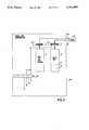
- FIG. 5is a flow diagram showing the transmission of data from the terminal server device memory to the LAN.
- FIG. 6is a diagrammatic representation illustrating the movement of data between the serial line interface and control modulus of the terminal server and a respective terminal.
- FIGS. 7a, 7b, 8a and 8bare diagrammatic representations for control for transmission of data between the terminal server device and a terminal.
- the present inventionrelates to a low cost, high efficiency terminal server architecture for transmitting data between a plurality of terminals and a local area network (LAN).
- the architecture of the present inventionremoves data transferring operations from being directly executed by the controller of the terminal server device. Accordingly, a simplified processor and other hardware to support the system replace a powerful processor and supporting hardware frequently found in prior art terminal server devices.
- the present inventionsupports the high data throughput required in present data network arrangements.
- FIG. 1shows the architecture according to the present invention implemented in a terminal server device 10.
- the terminal server 10includes a central processing unit (CPU) or microcontroller 12, RAM memory 14, a program store or ROM memory 16, and a data movement hardware module 20, discussed in greater detail herein.
- the CPU 12supplies and receives control signals to and from the data movement module 20 via a control bus 22.
- the CPU 12accesses the program store 16 via an address bus 24.
- the CPU 12receives data from the program store 16 via a data bus 26.
- the CPU 12may be an 80C51 family processor operating with a 10 MHz clock.
- the data movement modulealso provides control signals to memory 14 for reading and writing data via a bus 28. Likewise, control signals are also provided between a LAN interface controller 18 such as an 82590 CSMA/CD Ethernet controller manufactured by Intel as will be understood to those skilled in the art, and the data movement module 20 via a control bus 30.
- the data movement module 20specifies address information to memory 14 via an address bus 32. Data is supplied and received among the data movement module 20, terminal server memory 14, and the LAN interface controller 18 on a data bus 34.
- the data movement module 20sends data to and receives data from a plurality of terminals 36a through 36n.
- Each of the terminals 36a through 36nprovides serial characters of data to the data movement module 20 via serial data lines 38a through 38n and receives serial characters of data from the data movement module 20 via serial lines 40a through 40n.
- terminalis used herein to denote any number of data units which asynchronously receive and transmit data.
- FIG. 1also illustrates a representation in block form of the components of the data movement module 20.
- the data movement module 20is an application specific integrated circuit arranged in a 26K sea of gates CMOS array.
- the actual fabrication of hardware for implementing the data movement module 20is deemed to be within the skill of the art to which this invention pertains upon consideration of the functionality of the submodules described below.
- the data movement module 20includes a plurality of control status registers (CSRs) 35, a slot mover 38 of the type known in the art for moving blocks of data as described in greater detail below, a memory management portion 40, a transmit and receive engine 42 and a plurality of serial line controllers 44a through 44n, each connecting to a respective one of the terminals 36a through 36n via the serial transmission lines 38a through 38n and serial receiving lines 40a through 40n.
- CSRscontrol status registers
- FIG. 2aillustrates the organization of the terminal server memory 14 comprising 64K of RAM memory in the preferred embodiment.
- Data passed between the LAN and a selected terminalis placed into the terminal server memory 14 as an intermediate processing step.
- the memory management portion 40partitions the RAM memory 14 into pages 46a through 46n, preferably into 256 pages having 256 bytes per page. Packets of data requiring more than one page of memory are placed into memory blocks organized as a linked list.
- the content of the last byte of a previous page 46ais a pointer 48 to a next page 46b in a data packet buffer in the RAM memory 14, which will be understood to those skilled in the art as a construction of linked pages.
- the CPU 12 or the data movement module 20builds a linked page list.
- the pointer to the first page in this bufferis contained in LAN Transmit and Receive Queue CSRs 35 as shown in Table I below.
- Pointers to free memoryare also contained on a stack accessed through in a Free Memory Stack CSR 36 (see Table I). Both the data movement module 20 and the CPU 12 allocate memory by popping pointers from the Free Memory Stack CSR 35, and de-allocate memory by pushing pointers back onto the Free Memory Stack CSR.
- FIG. 3shows a memory map according to the preferred embodiment.
- page zero 50 of memoryis mapped to the control status registers (CSRs) 35.
- the CPU 12asserts command signals that set bits in selected bit positions in the data fields of the CSRs 35 to direct the data movement module 20 to perform specified operations.
- the data movement module 20also sets appropriate bits in the CSRs 35 to inform the CPU 12 of status and other information during movement operations as described below.
- the LAN interface controllersets bits in the CSRs 35 to request data transmission to the terminal server 10 and to acknowledge receipt of data supplied from the terminal server 10.
- the following tableshows the CSRs 35 provided and their function according to the preferred embodiment:
- FIG. 3also illustrates the allocation of the remaining pages of memory 14.
- Page one 52 of memory 14is used to store a LAN receive queue.
- the LAN receive queueis a linear list which stores pointers to data packets that have been received.
- Page two 54 of memorystores a LAN transmit queue. While the CPU 12 reads or writes to the Transmit Queue CSR and the Receive Queue CSR, pages one and two of memory represent the actual storage location for the transmit queue and receive queue pointers.
- a memory block 56 including pages three throughare freely accessible for storage and retrieval of data packets received from the LAN.
- a memory block 58 including pages 192 through 255are used for storage and retrieval of data received from respective terminals via the serial line input/output FIFOs 44a through 44n.
- the data movement module 20operates with a 300 nanosecond (ns) memory cycle for reading from or writing to the memory 14.
- the terminal server 10further operates on a 2400 ns time consisting of eight memory cycles.
- the CPU 12addresses the memory 14 in a transparent, wait-free access fashion according to the following priority scheme: (1) the CPU 12 has first priority; (2) the LAN transmission and receive engine second; (3) the serial line FIFOs 44a through 44n third; and (4) the slot mover 38 last. Accordingly, a large bandwidth is provided for the data movement module 20 for accessing the memory 14 before returning control of the data bus 32 and address bus 34 to the CPU 12.
- the DMA transmit and receive engine 42performs direct memory access transfers of data between the LAN interface controller 18 and memory 14 for both receive and transmit operations.
- FIG. 4ashows the sequence of operations for receiving data packets from the LAN and thereafter placing the data into memory 14.
- the CPU 12enables data packet reception by "arming" the DMA receive engine 42.
- the CPU 12initially arms the DMA receive engine 42 by asserting a command signal that sets an "arm" bit 60 in the second bit position in the data field for the DMA Transmit and Receive CSR 35a.
- the CPU 12thereafter asserts a command signal that sets a bit in the data field of the LAN interface controller CSR specifying an appropriate data channel as will be understood to those skilled in the art.
- the receive engine 42When the LAN receive engine 42 is armed, the receive engine 42 immediately pops the pointer to the next available free memory page from the free memory stack CSR.
- the LAN interface controller 18thereafter asserts a direct memory access (DMA) request control signal, which results in the setting of a selected bit in the data field of the LAN Interface Controller Status CSR (Table I).
- DMAdirect memory access
- Table IThe DMA receive engine 42 uses the pointer corresponding to the free memory page previously popped from the Free Memory Stack CSR (see Table I), and moves the packet directly from the LAN interface controller 18 to that page.
- FIG. 4aalso illustrates a reception sequence wherein the data packet size intended to be received exceeds 255 bytes.
- the receive engine 42allocates another free page of memory from the stack by popping the address of the next succeeding page of available memory from the Free Memory Stack CSR (Table I).
- the receive engine 42thereafter places a pointer to the next succeeding page in the last location (255) of the current page as shown in FIG. 2b.
- the receive engine 42continues transferring data to the new page.
- the receive engine 42writes an appropriate message to the location in the last page of the packet.
- the CPU 12may disarm the receive engine 42 during packet reception.
- the CPU 12disarms the LAN receive engine 42 by asserting a command signal that clears the "arm" bit 60 in the DMA Transmit and Receive CSR 35a.
- the DMA receive engine 42writes a different message to location 255 in the last page of the packet received before the DMA receive engine 42 was disarmed.
- the LAN interface controller 18Upon completion of a packet reception, the LAN interface controller 18 writes a completion message to memory and asserts an interrupt signal to the CPU 12.
- the DMA receive engine 42reads the LAN Interface Controller Status CSR (Table I), and writes a code into location 255 of the last page in the data packet buffer. The DMA receive engine 42 thereafter clears the LAN interface controller interrupt.
- the message written by the DMA receive engine 42corresponds to the following conditions: (1) data received OK; (2) arm bit cleared while receiving a packet; (3) memory could not be allocated; or (4) receive error detected.
- the DMA receive engine 42thereafter places a pointer to the address of the first page of the location of the data packet in the Receive Queue CSR (Table I).
- the CPU 12accesses the receive queue pointers by reading the Receive Queue CSR. Once the CPU 12 reads the pointer, it is removed from the queue.
- the CPU 12uses the linked list memory structure to access all memory pages in the packet as described above.
- the last memory location of the last page in the buffer containing the data packetcontains status information supplied by the DMA receive engine 42.
- the CPU 12processes this location, and thereafter redirects the packet of data received in memory 14 to a selected serial line controller 44a through 44n, as described below.
- the CPU 12places it back on the free memory stack by writing the pointer to the Free Memory Stack.
- FIG. 4aalso illustrates the situation in which the DMA receive engine 42 is initially armed and no free memory is available.
- the DMA receive engine 42asserts a command signal to set the bit in a "no memory" bit position in the data field for the DMA Transmit and Receive CSR.
- the CPU 12Upon receipt of this information, the CPU 12 is interrupted. The CPU 12 polls the no memory bit to determine the cause of the interrupt, and thereafter takes appropriate action.
- Datais transmitted from the terminal server 10 to the LAN in the sequence of operations shown in FIG. 5.
- the CPU 12initiates a transmit operation by placing a pointer to the first page of a packet on the Transmit Queue.
- the CPU 12also asserts a command signal to set a selected bit in the data field of the DMA Transmit and Receive CSR 35a to "arm" the engine 42.
- the CPU 12thereafter organizes the data ready to be transmitted into a linked list of pages, with pointers to subsequent pages in the last location (location 255) of the previous page.
- the DMA transmit engine 42reads the contents of the Transmit Queue CSR 36.
- the DMA transmit engine 42thereafter issues a command signal for requesting transmission to the LAN control interface controller 18 by writing a transmit command message to the LAN Interface Control CSR (Table I).
- the LAN Interface Controller 18Upon receipt of the data transmission request, the LAN Interface Controller 18 asserts a direct memory access request by setting a selected bit in the data field of the LAN Interface Control CSR (Table I).
- the DMA transmit engine 42thereafter sequences through the Transmit Queue and automatically transmits all the packets listed in the Transmit Queue CSR.
- the LAN transmit engine 42retrieves a pointer to the location of the next succeeding page of the data packet in memory 14 from the Transmit Queue CSR. Upon selection of the address of the next succeeding page, the next succeeding page is moved from memory 14 to the LAN Interface Controller 18.
- the LAN Interface Controller 18supplies an interrupt command signal to the DMA transmit engine 42 when transmission of a packet of data is complete. In addition the LAN Interface Controller 18 asserts a command signal to selected bits in the LAN Interface Controller. The LAN transmit engine 42 thereafter polls the contents of the LAN Interface Controller CSR. Upon the occurrence of a normal transmission, the DMA transmit engine 42 writes its current status in the last byte of the last page of the buffer, and clears the interrupt.
- the DMA transmit engine 42determines whether a collision of data packets occurred. If a collision occurred, the DMA transmit engine 42 sequences to the address corresponding to the first page of the data packet. The DMA transmit engine 42 also supplies a retransmit command signal to the LAN Interface Controller 18 by setting a selected bit in the LAN Interface Controller CSR. Data is thereafter supplied to the LAN Interface Controller 18 as described above.
- the DMA transmit engineasserts a command signal to interrupt control of the CPU 12.
- the CPU 12thereafter acknowledges the interrupt signal asserted by the LAN Interface Controller 18.
- FIG. 6shows a block diagram for one of the plurality of serial line controllers 44a through 44n.
- the serial line controller 44aprovides a Universal Asynchronous Receive and Transmit (UART) function as will be understood to those skilled in the art.
- the CPU 12may provide command signals to set appropriate bit positions the UART CSR data field (as described in Table I) to control the transmission rate as well as other parameters.
- the CPU 12polls selected bit positions in the UART CSR to detect data framing errors and other status signals provide by the serial line controller 44a as is well known in the art.
- the serial line controller 44aincludes a first-in first-out (FIFO) transmission serial line mover 62 and a receive FIFO 66.
- the transmission serial line mover 62provides asynchronous characters of data to a serial line inserter 68, which in turn, provides data to the terminal 36a via the line 40a.
- data supplied from the terminal 36ais received by a serial line transmission detector 70 on the line 38a.
- the detector 70thereafter supplies characters of data to the receive FIFO 66.
- the detector 70senses either a transmission on ("XON") or a transmission off (“XOFF”) signal provided by the terminal 36a for a data transmission request on the line 38a.
- the inserter 68supplies a data transmission request to the terminal 36a via the line 40a.
- FIG. 6also illustrates the flow control CSR 35b provided for the singular serial line controller 44a.
- the remaining serial line controllers 44b through 44n corresponding to the remaining terminals 36b through 36n connected with the terminal server 10perform in exactly the same manner.
- the method for enabling the serial line controller 44a to process either a transmission on ("XON") or transmission off (“XOFF”) signal received from the terminal 36ais also shown in FIG. 6, and in FIGS. 7a and 7b.
- the CPU 12asserts a command signal to set a bit in the first bit position 72 of the Flow Control CSR 35b.
- the reception of an XON command signal from the terminal 36asets a bit in the third bit position 74 of the Flow Control CSR 35b to enable the transmission serial line mover 62 to pass characters of data to the terminal 36a via the line 40a.
- the CPU 12may also assert a command signal to set the bit position 74 of the Flow Control CSR 35b for instructing the serial line mover 62 to begin transmission.
- the terminal 36asends an XOFF signal
- data transmission from the serial line mover 62 to the terminal 36ais suspended.
- the CPU 12may assert a command signal to clear the bit position 74 to terminate the data transmission. If enabled in the direction of the terminal server to the terminal, and the serial line controller 44a concurrently receives an XOFF signal from the terminal, character output is discontinued until either (1) an XON signal is received, or (2) the CPU 12 changes the flow control state.
- FIGS. 8a and 8billustrate data movement from the terminal 36a to the receive FIFO 66.
- the CPU 12asserts a command signal to set the bit corresponding to a receive enable bit position 76 in the Flow Control CSR 35b.
- the receive FIFO 66thereafter receives characters of data from the terminal 36a via the line 38a.
- the serial line controller 44aWhen the amount of data received exceeds a first "high water” mark 80, corresponding to the number of locations in the receive FIFO 66 (for example 896 bytes in the preferred embodiment), the serial line controller 44a generates a first command "XOFF" signal to the terminal 36a.
- the serial line controller 44agenerates a second command "XOFF" signal to the terminal 36a when the amount of data received exceeds a second "high water” mark 82, corresponding to the number of locations filled with data in the receive FIFO 66 (for example 960 bytes).
- the CPU 12thereafter asserts a command signal to set the bit corresponding to a Terminal XOFFed bit position 78 in the flow Control CSR 35b.
- the terminal 36aterminates data transmission to the receive FIFO 66.
- the CPU 12thereafter directs data in the receive FIFO 66 to memory 14 by asserting command signals to perform a slot move operation, as described below.
- the CPU 12must thereafter supply a command signal to clear the Terminal XOFFed bit.
- This command signalcauses the serial line inserter 68 to supply a data transmission request (an "XON" command) signal to the terminal 36a via the line 40a, to allow retransmission by the terminal 36a.
- the slot mover 38provides rapid movement of blocks of data as will be understood by those skilled in the art for moving data to and from one memory block to another, or to and from CSRs.
- slot mover applicationsinclude moving slot data into and out of serial line FIFO's, loading or unloading, transmit or receive buffers, or configuring the LAN controller 18.
- the slot mover 38is restricted to transfers to and from a single page of memory.
- the CPU 12To perform a slot movement of data, the CPU 12 generates the appropriate command signals corresponding to a source address, destination address and number of bytes to be moved. In particular, the CPU 12 specifies the appropriate destination page and location within the page by providing command signals to set selected bits in the slot Move Destination HI and LO CSRs (Table I). Similarly, the desired source page and location within the page are specified by the CPU 12 in the Slot Source HI and LO CSRs. The CPU 12 writes such information to the Slot Move CSRs as shown in Table I. The source and destination CSRs provide a page number for movement of the block.
- terminal server architectureproviding a relatively inexpensive cost for implementation thereof.
- the terminal server architecturerelieves a microcontroller of direct data movements. Instead, the CPU manipulates pointers to data which direct supporting logic to perform actual data moves.
Landscapes
- Engineering & Computer Science (AREA)
- Theoretical Computer Science (AREA)
- Computer Hardware Design (AREA)
- Microelectronics & Electronic Packaging (AREA)
- Physics & Mathematics (AREA)
- General Engineering & Computer Science (AREA)
- General Physics & Mathematics (AREA)
- Computer Networks & Wireless Communication (AREA)
- Signal Processing (AREA)
- Small-Scale Networks (AREA)
- Computer And Data Communications (AREA)
- Information Transfer Systems (AREA)
Abstract
Description
TABLE I ______________________________________ CSR Application ______________________________________ CSRs For Controlling Transmission OfData 1. LAN Interface Controller Initializes LAN Inter-Initialize face Controller 18 2. LAN Interface Controller Provides bits for con- Command and Status trolling the LAN Inter-face Controller 18 3. LAN Transmit Queue Stores pointers to pages in memory containing data packets waiting to be transmitted. 4. LAN Receive Queue Stores pointers to pages in memory containing data packets that have been received. 5. Free Memory Stack Stores pointers to free pages in memory. 6. DMA Transmit and Receive Arms theDMA engine 42 Enable and Status for receiving and transmitting data toterminal server memory 14, and reports status. CSRs ForSlot Move Operations 1. Slot Move Counter Stores number of bytes to move in a slot move operation. 2. Slot Move Destination HI Stores page in memory to move to in slot move operation. 3. Slot Move Destination LO Stores offset memory location in page to move to. 4. Slot Source HI Stores page in memory to move from. 5. Slot Source LO Stores offset memory location in page to move from. CSRs For Controlling Transmission Of Data Between Memory AndTerminals 1. Flow Control CSR Enables/disables serial ports for serial data transmission and reception. 2. Universal Asynchronous Controls baud rate and Receiver/Transmitter (UART) loopback modes for serial transmission from theterminal server 10 to selected terminals. 3. Receive FIFO Stores characters received from UART in 1024 byte FIFO's. 4. Low Receive Count Stores low order byte of character count in receive FIFO. 5. High ReceiveCount Stores 2 most signifi- cant bits of character count in receive FIFO. 6. Transmit FIFO Stores characters wait- ing to be transmitted to UART's in 1024 byte FIFO's. 7. Low Transmit Count Stores low order byte of character count in transmit FIFO. 8. High TransmitCount Stores 2 most signifi- cant bits of character count in transmit FIFO. ______________________________________
Claims (5)
Priority Applications (7)
| Application Number | Priority Date | Filing Date | Title |
|---|---|---|---|
| US07/546,104US5151895A (en) | 1990-06-29 | 1990-06-29 | Terminal server architecture |
| CA002041741ACA2041741C (en) | 1990-06-29 | 1991-05-02 | Terminal server architecture |
| GB9109915AGB2248007B (en) | 1990-06-29 | 1991-05-08 | Terminal server architecture |
| KR1019910008905AKR940011490B1 (en) | 1990-06-29 | 1991-05-30 | Data transfer between local area network and selected terminal Terminal server and data passing method |
| FR9107446AFR2664070B1 (en) | 1990-06-29 | 1991-06-18 | ARCHITECTURE OF A TERMINAL SERVER. |
| JP3157003AJPH0731649B2 (en) | 1990-06-29 | 1991-06-27 | Terminal server architecture |
| DE4121446ADE4121446C2 (en) | 1990-06-29 | 1991-06-28 | Terminal Server Architecture |
Applications Claiming Priority (1)
| Application Number | Priority Date | Filing Date | Title |
|---|---|---|---|
| US07/546,104US5151895A (en) | 1990-06-29 | 1990-06-29 | Terminal server architecture |
Publications (1)
| Publication Number | Publication Date |
|---|---|
| US5151895Atrue US5151895A (en) | 1992-09-29 |
Family
ID=24178885
Family Applications (1)
| Application Number | Title | Priority Date | Filing Date |
|---|---|---|---|
| US07/546,104Expired - LifetimeUS5151895A (en) | 1990-06-29 | 1990-06-29 | Terminal server architecture |
Country Status (7)
| Country | Link |
|---|---|
| US (1) | US5151895A (en) |
| JP (1) | JPH0731649B2 (en) |
| KR (1) | KR940011490B1 (en) |
| CA (1) | CA2041741C (en) |
| DE (1) | DE4121446C2 (en) |
| FR (1) | FR2664070B1 (en) |
| GB (1) | GB2248007B (en) |
Cited By (18)
| Publication number | Priority date | Publication date | Assignee | Title |
|---|---|---|---|---|
| US5301287A (en)* | 1990-03-12 | 1994-04-05 | Hewlett-Packard Company | User scheduled direct memory access using virtual addresses |
| US5311515A (en)* | 1992-02-07 | 1994-05-10 | Sim Ware, Incorporated | Method and apparatus for the control of local area network multi-station access units |
| EP0616450A3 (en)* | 1993-03-05 | 1995-12-13 | Toshiba Kk | Communication control device. |
| US5530702A (en)* | 1994-05-31 | 1996-06-25 | Ludwig Kipp | System for storage and communication of information |
| US5649122A (en)* | 1994-06-24 | 1997-07-15 | Startech Semiconductor, Inc. | Universal asynchronous receiver/transmitter with programmable xon/xoff characters |
| US5664101A (en)* | 1993-12-22 | 1997-09-02 | Heidelberg Druckmaschinen Ag | Intelligent industrial local area network module for use in a distributed control system |
| FR2753030A1 (en)* | 1996-08-27 | 1998-03-06 | Derif | Access server equipment for transfer of data to and from PCMCIA cards |
| USRE36109E (en)* | 1991-04-30 | 1999-02-23 | Kipp; Ludwig | Checkout system |
| US5893148A (en)* | 1994-03-03 | 1999-04-06 | International Business Machines Corporation | System and method for allocating cache memory storage space |
| US20020026549A1 (en)* | 2000-08-30 | 2002-02-28 | Powers Tracy D. | Remote reconfiguration system |
| US20030202217A1 (en)* | 1991-11-07 | 2003-10-30 | Canon Kabushiki Kaisha | Facsimile system |
| EP0952716A3 (en)* | 1998-04-03 | 2005-04-06 | Applied Microcircuits Corporation | System and method for data transformation and transfer in networks |
| US7046686B1 (en)* | 1999-08-17 | 2006-05-16 | Mindspeed Technologies, Inc. | Integrated circuit that processes communication packets with a buffer management engine having a pointer cache |
| US20070002853A1 (en)* | 2005-06-30 | 2007-01-04 | Anil Vasudevan | Snoop bandwidth reduction |
| US20070172394A1 (en)* | 2006-01-20 | 2007-07-26 | Schulz Bradley D | Specimen containment module for orthopedic simulator |
| US7271924B1 (en)* | 1999-10-15 | 2007-09-18 | Seiko Epson Corporation | Printer, control method for the same, and control device |
| US9002512B2 (en) | 2008-06-04 | 2015-04-07 | Samsung Electronics Co., Ltd. | Robot and method of controlling walking thereof |
| US10303630B2 (en)* | 2017-10-08 | 2019-05-28 | Huawei Technologies Co., Ltd. | Configurable hardware accelerators |
Families Citing this family (15)
| Publication number | Priority date | Publication date | Assignee | Title |
|---|---|---|---|---|
| GB2277425B (en)* | 1993-04-23 | 1997-08-06 | Motorola Inc | Message communication system |
| US6067408A (en)* | 1993-05-27 | 2000-05-23 | Advanced Micro Devices, Inc. | Full duplex buffer management and apparatus |
| JP3274293B2 (en)* | 1994-10-13 | 2002-04-15 | 富士通株式会社 | Signal processing device |
| GB2337861B (en)* | 1995-06-02 | 2000-02-23 | Dsc Communications | Integrated directional antenna |
| US5745496A (en)* | 1995-06-02 | 1998-04-28 | Dsc Communications Corporation | Apparatus and method of establishing a downlink communication path in a wireless telecommunications system |
| US5809093A (en)* | 1995-06-02 | 1998-09-15 | Dsc Communications Corporation | Apparatus and method of frame aligning information in a wireless telecommunications system |
| GB2302240B (en)* | 1995-06-02 | 2000-01-12 | Dsc Communications | Apparatus and method of frame aligning information in a wireless telecommunications system |
| US5696766A (en)* | 1995-06-02 | 1997-12-09 | Dsc Communications Corporation | Apparatus and method of synchronizing a transmitter in a subscriber terminal of a wireless telecommunications system |
| US5742595A (en)* | 1995-06-02 | 1998-04-21 | Dsc Communications Corporation | Processing CDMA signals |
| GB2301735B (en)* | 1995-06-02 | 1999-07-28 | Dsc Communications | Message handling in a telecommunications network |
| GB2301717B (en)* | 1995-06-02 | 1999-08-11 | Dsc Communications | Network controller for monitoring the status of a network |
| US5915216A (en)* | 1995-06-02 | 1999-06-22 | Dsc Communications Corporation | Apparatus and method of transmitting and receiving information in a wireless telecommunications system |
| GB2301751B (en)* | 1995-06-02 | 2000-02-09 | Dsc Communications | Control message transmission in telecommunications systems |
| GB2301752B (en)* | 1995-06-02 | 2000-03-29 | Dsc Communications | Control message transmission in telecommunications systems |
| GB9511844D0 (en)* | 1995-06-10 | 1995-08-09 | Plessey Telecomm | Atm local access |
Citations (10)
| Publication number | Priority date | Publication date | Assignee | Title |
|---|---|---|---|---|
| US4225919A (en)* | 1978-06-30 | 1980-09-30 | Motorola, Inc. | Advanced data link controller |
| EP0064347A1 (en)* | 1981-04-22 | 1982-11-10 | Pitney Bowes, Inc. | Local network interface for use in multi-station word processing system and a data communications network |
| US4455647A (en)* | 1982-06-14 | 1984-06-19 | Siemens Corporation | Apparatus for establishing multi-address connections |
| US4547880A (en)* | 1983-05-13 | 1985-10-15 | Able Computer | Communication control apparatus for digital devices |
| EP0185122A1 (en)* | 1984-11-19 | 1986-06-25 | Aetna Telecommunications Laboratories | Three level distributed control for networking I/O devices |
| US4623997A (en)* | 1984-12-13 | 1986-11-18 | United Technologies Corporation | Coherent interface with wraparound receive and transmit memories |
| US4695997A (en)* | 1984-06-29 | 1987-09-22 | International Business Machines Corporation | Device for performing wrap tests on a multiplex link in a data communication system |
| US4706081A (en)* | 1984-12-14 | 1987-11-10 | Vitalink Communications Corporation | Method and apparatus for bridging local area networks |
| US4872159A (en)* | 1988-03-31 | 1989-10-03 | American Telephone And Telegraph Company At&T Bell Laboratories | Packet network architecture for providing rapid response time |
| US4887075A (en)* | 1987-06-19 | 1989-12-12 | Kabushiki Kaisha Toshiba | Local area network system with a multi-computer system coupled thereto and method for controlling the same |
Family Cites Families (5)
| Publication number | Priority date | Publication date | Assignee | Title |
|---|---|---|---|---|
| EP0133117A3 (en)* | 1983-07-20 | 1988-01-27 | FAIRCHILD CAMERA & INSTRUMENT CORPORATION | Independently operable local area network |
| JPS62174852A (en)* | 1986-01-28 | 1987-07-31 | Nec Corp | Receiving control method in data transmission system |
| JPH01190065A (en)* | 1988-01-25 | 1989-07-31 | Mitsubishi Electric Corp | Terminal control system |
| JPH01216649A (en)* | 1988-02-24 | 1989-08-30 | Oki Electric Ind Co Ltd | Distribution output method for information |
| JPH0776939B2 (en)* | 1988-03-16 | 1995-08-16 | 富士ゼロックス株式会社 | Communication network system |
- 1990
- 1990-06-29USUS07/546,104patent/US5151895A/ennot_activeExpired - Lifetime
- 1991
- 1991-05-02CACA002041741Apatent/CA2041741C/ennot_activeExpired - Fee Related
- 1991-05-08GBGB9109915Apatent/GB2248007B/ennot_activeExpired - Fee Related
- 1991-05-30KRKR1019910008905Apatent/KR940011490B1/ennot_activeExpired - Fee Related
- 1991-06-18FRFR9107446Apatent/FR2664070B1/ennot_activeExpired - Fee Related
- 1991-06-27JPJP3157003Apatent/JPH0731649B2/ennot_activeExpired - Lifetime
- 1991-06-28DEDE4121446Apatent/DE4121446C2/ennot_activeExpired - Fee Related
Patent Citations (10)
| Publication number | Priority date | Publication date | Assignee | Title |
|---|---|---|---|---|
| US4225919A (en)* | 1978-06-30 | 1980-09-30 | Motorola, Inc. | Advanced data link controller |
| EP0064347A1 (en)* | 1981-04-22 | 1982-11-10 | Pitney Bowes, Inc. | Local network interface for use in multi-station word processing system and a data communications network |
| US4455647A (en)* | 1982-06-14 | 1984-06-19 | Siemens Corporation | Apparatus for establishing multi-address connections |
| US4547880A (en)* | 1983-05-13 | 1985-10-15 | Able Computer | Communication control apparatus for digital devices |
| US4695997A (en)* | 1984-06-29 | 1987-09-22 | International Business Machines Corporation | Device for performing wrap tests on a multiplex link in a data communication system |
| EP0185122A1 (en)* | 1984-11-19 | 1986-06-25 | Aetna Telecommunications Laboratories | Three level distributed control for networking I/O devices |
| US4623997A (en)* | 1984-12-13 | 1986-11-18 | United Technologies Corporation | Coherent interface with wraparound receive and transmit memories |
| US4706081A (en)* | 1984-12-14 | 1987-11-10 | Vitalink Communications Corporation | Method and apparatus for bridging local area networks |
| US4887075A (en)* | 1987-06-19 | 1989-12-12 | Kabushiki Kaisha Toshiba | Local area network system with a multi-computer system coupled thereto and method for controlling the same |
| US4872159A (en)* | 1988-03-31 | 1989-10-03 | American Telephone And Telegraph Company At&T Bell Laboratories | Packet network architecture for providing rapid response time |
Cited By (23)
| Publication number | Priority date | Publication date | Assignee | Title |
|---|---|---|---|---|
| US5301287A (en)* | 1990-03-12 | 1994-04-05 | Hewlett-Packard Company | User scheduled direct memory access using virtual addresses |
| USRE36109E (en)* | 1991-04-30 | 1999-02-23 | Kipp; Ludwig | Checkout system |
| US7110134B2 (en)* | 1991-11-07 | 2006-09-19 | Canon Kabushiki Kaisha | Facsimile system |
| US20030202217A1 (en)* | 1991-11-07 | 2003-10-30 | Canon Kabushiki Kaisha | Facsimile system |
| US5311515A (en)* | 1992-02-07 | 1994-05-10 | Sim Ware, Incorporated | Method and apparatus for the control of local area network multi-station access units |
| EP0616450A3 (en)* | 1993-03-05 | 1995-12-13 | Toshiba Kk | Communication control device. |
| US5664101A (en)* | 1993-12-22 | 1997-09-02 | Heidelberg Druckmaschinen Ag | Intelligent industrial local area network module for use in a distributed control system |
| US5893148A (en)* | 1994-03-03 | 1999-04-06 | International Business Machines Corporation | System and method for allocating cache memory storage space |
| US5530702A (en)* | 1994-05-31 | 1996-06-25 | Ludwig Kipp | System for storage and communication of information |
| US5649122A (en)* | 1994-06-24 | 1997-07-15 | Startech Semiconductor, Inc. | Universal asynchronous receiver/transmitter with programmable xon/xoff characters |
| FR2753030A1 (en)* | 1996-08-27 | 1998-03-06 | Derif | Access server equipment for transfer of data to and from PCMCIA cards |
| EP0952716A3 (en)* | 1998-04-03 | 2005-04-06 | Applied Microcircuits Corporation | System and method for data transformation and transfer in networks |
| USRE42092E1 (en) | 1999-08-17 | 2011-02-01 | Tompkins Joseph B | Integrated circuit that processes communication packets with a buffer management engine having a pointer cache |
| US7046686B1 (en)* | 1999-08-17 | 2006-05-16 | Mindspeed Technologies, Inc. | Integrated circuit that processes communication packets with a buffer management engine having a pointer cache |
| US7515286B2 (en) | 1999-10-15 | 2009-04-07 | Seiko Epson Corporation | Printer, control method for the same, and control device |
| US7271924B1 (en)* | 1999-10-15 | 2007-09-18 | Seiko Epson Corporation | Printer, control method for the same, and control device |
| US20070296999A1 (en)* | 1999-10-15 | 2007-12-27 | Seiko Epson Corporation | Printer, Control Method For The Same, And Control Device |
| US7269641B2 (en)* | 2000-08-30 | 2007-09-11 | Sun Microsystems, Inc. | Remote reconfiguration system |
| US20020026549A1 (en)* | 2000-08-30 | 2002-02-28 | Powers Tracy D. | Remote reconfiguration system |
| US20070002853A1 (en)* | 2005-06-30 | 2007-01-04 | Anil Vasudevan | Snoop bandwidth reduction |
| US20070172394A1 (en)* | 2006-01-20 | 2007-07-26 | Schulz Bradley D | Specimen containment module for orthopedic simulator |
| US9002512B2 (en) | 2008-06-04 | 2015-04-07 | Samsung Electronics Co., Ltd. | Robot and method of controlling walking thereof |
| US10303630B2 (en)* | 2017-10-08 | 2019-05-28 | Huawei Technologies Co., Ltd. | Configurable hardware accelerators |
Also Published As
| Publication number | Publication date |
|---|---|
| CA2041741C (en) | 1996-09-24 |
| DE4121446A1 (en) | 1992-01-16 |
| FR2664070A1 (en) | 1992-01-03 |
| GB9109915D0 (en) | 1991-07-03 |
| FR2664070B1 (en) | 1993-09-24 |
| JPH04233055A (en) | 1992-08-21 |
| GB2248007B (en) | 1994-06-01 |
| GB2248007A (en) | 1992-03-18 |
| DE4121446C2 (en) | 2003-03-27 |
| KR920001891A (en) | 1992-01-30 |
| JPH0731649B2 (en) | 1995-04-10 |
| KR940011490B1 (en) | 1994-12-19 |
| CA2041741A1 (en) | 1991-12-30 |
Similar Documents
| Publication | Publication Date | Title |
|---|---|---|
| US5151895A (en) | Terminal server architecture | |
| JP3336816B2 (en) | Multimedia communication device and method | |
| US5923660A (en) | Switching ethernet controller | |
| US5530874A (en) | Network adapter with an indication signal mask and an interrupt signal mask | |
| US5732094A (en) | Method for automatic initiation of data transmission | |
| US5315708A (en) | Method and apparatus for transferring data through a staging memory | |
| US7450583B2 (en) | Device to receive, buffer, and transmit packets of data in a packet switching network | |
| US5367643A (en) | Generic high bandwidth adapter having data packet memory configured in three level hierarchy for temporary storage of variable length data packets | |
| US5043938A (en) | Node controller for a local area network | |
| AU4435699A (en) | Optimizing the transfer of data packets between lans | |
| US5347514A (en) | Processor-based smart packet memory interface | |
| US5923852A (en) | Method and system for fast data transmissions in a processing system utilizing interrupts | |
| GB2349717A (en) | Low latency network | |
| US6061748A (en) | Method and apparatus for moving data packets between networks while minimizing CPU intervention using a multi-bus architecture having DMA bus | |
| US5961614A (en) | System for data transfer through an I/O device using a memory access controller which receives and stores indication of a data status signal | |
| US5488734A (en) | Coupler for providing a high speed interface between a communication controller and a controller extension | |
| US20030065735A1 (en) | Method and apparatus for transferring packets via a network | |
| US20040151175A1 (en) | Transparent data format within host device supporting differing transaction types | |
| US5432910A (en) | Coupling apparatus and method for increasing the connection capability of a communication system | |
| US6769055B1 (en) | Two-part memory address generator | |
| GB2226739A (en) | Node controller for local area network | |
| JP2000259523A (en) | Data transfer device, lan communication system and data transfer method | |
| WO1991013397A1 (en) | A method and apparatus for transferring data through a staging memory | |
| Protogeros et al. | Traffic analyser and generator Part 1: High-speed traffic capture for IEEE 802.3/Ethernet networks | |
| Skibo | A BSD Network Interface Driver for HIPPI |
Legal Events
| Date | Code | Title | Description |
|---|---|---|---|
| AS | Assignment | Owner name:DIGITAL EQUIPMENT CORPORATION, MASSACHUSETTS Free format text:ASSIGNMENT OF ASSIGNORS INTEREST.;ASSIGNORS:VACON, GARY;ENGELSE, WILLEM A.H.;METZGER, STEPHEN D.;AND OTHERS;REEL/FRAME:005424/0434;SIGNING DATES FROM 19900808 TO 19900820 | |
| STCF | Information on status: patent grant | Free format text:PATENTED CASE | |
| FEPP | Fee payment procedure | Free format text:PAYOR NUMBER ASSIGNED (ORIGINAL EVENT CODE: ASPN); ENTITY STATUS OF PATENT OWNER: LARGE ENTITY | |
| FPAY | Fee payment | Year of fee payment:4 | |
| AS | Assignment | Owner name:CABLETRON SYSTEMS, INC., NEW HAMPSHIRE Free format text:ASSIGNMENT OF ASSIGNORS INTEREST;ASSIGNOR:DIGITAL EQUIPMENT CORPORATION;REEL/FRAME:009046/0792 Effective date:19980206 | |
| FEPP | Fee payment procedure | Free format text:PAYER NUMBER DE-ASSIGNED (ORIGINAL EVENT CODE: RMPN); ENTITY STATUS OF PATENT OWNER: LARGE ENTITY | |
| FPAY | Fee payment | Year of fee payment:8 | |
| FPAY | Fee payment | Year of fee payment:12 | |
| AS | Assignment | Owner name:OBSIDIAN, LLC, CALIFORNIA Free format text:SECURITY AGREEMENT;ASSIGNOR:ENTERASYS NETWORKS, INC.;REEL/FRAME:017656/0552 Effective date:20060516 Owner name:WELLS FARGO FOOTHILL, INC., CALIFORNIA Free format text:SECURITY AGREEMENT;ASSIGNOR:ENTERASYS NETWORKS, INC.;REEL/FRAME:017656/0552 Effective date:20060516 | |
| AS | Assignment | Owner name:ENTERASYS NETWORKS, INC., MASSACHUSETTS Free format text:RELEASE AND REASSIGNMENT OF PATENTS AND PATENT APPLICATIONS AT REEL/FRAME NO. 17656/0552;ASSIGNORS:WELLS FARGO CAPITAL FINANCE, INC. (FORMERLY KNOWN AS WELLS FARGO FOOTHILL, INC.);ENTERPRISE COMMUNICATIONS FUNDING GMBH, AS SUCCESSOR IN INTEREST TO OBSIDIAN, LLC;REEL/FRAME:025406/0769 Effective date:20101110 |