US5151800A - Compact hologram displays & method of making compact hologram - Google Patents
Compact hologram displays & method of making compact hologramDownload PDFInfo
- Publication number
- US5151800A US5151800AUS07/627,984US62798490AUS5151800AUS 5151800 AUS5151800 AUS 5151800AUS 62798490 AUS62798490 AUS 62798490AUS 5151800 AUS5151800 AUS 5151800A
- Authority
- US
- United States
- Prior art keywords
- hologram
- reflective
- edge
- display apparatus
- opposing
- Prior art date
- Legal status (The legal status is an assumption and is not a legal conclusion. Google has not performed a legal analysis and makes no representation as to the accuracy of the status listed.)
- Expired - Lifetime
Links
- 238000004519manufacturing processMethods0.000title1
- 239000007787solidSubstances0.000claimsabstractdescription12
- 239000011248coating agentSubstances0.000claimsdescription10
- 238000000576coating methodMethods0.000claimsdescription10
- 230000003287optical effectEffects0.000claimsdescription6
- 239000006185dispersionSubstances0.000claimsdescription4
- 238000000034methodMethods0.000claimsdescription2
- 230000001427coherent effectEffects0.000claims1
- 238000009877renderingMethods0.000claims1
- 239000011521glassSubstances0.000abstractdescription24
- 230000005540biological transmissionEffects0.000description11
- 239000000839emulsionSubstances0.000description5
- 239000004568cementSubstances0.000description4
- 239000003570airSubstances0.000description3
- 238000005286illuminationMethods0.000description3
- 239000013307optical fiberSubstances0.000description3
- 230000008859changeEffects0.000description2
- 238000012937correctionMethods0.000description2
- 239000007788liquidSubstances0.000description2
- VVQNEPGJFQJSBK-UHFFFAOYSA-NMethyl methacrylateChemical compoundCOC(=O)C(C)=CVVQNEPGJFQJSBK-UHFFFAOYSA-N0.000description1
- 229920005372Plexiglas®Polymers0.000description1
- 239000012080ambient airSubstances0.000description1
- 238000009833condensationMethods0.000description1
- 230000005494condensationEffects0.000description1
- 230000008878couplingEffects0.000description1
- 238000010168coupling processMethods0.000description1
- 238000005859coupling reactionMethods0.000description1
- 238000013461designMethods0.000description1
- 238000011161developmentMethods0.000description1
- 230000018109developmental processEffects0.000description1
- 239000000428dustSubstances0.000description1
- 239000005357flat glassSubstances0.000description1
- 230000002452interceptive effectEffects0.000description1
- 239000000463materialSubstances0.000description1
- 238000012986modificationMethods0.000description1
- 230000004048modificationEffects0.000description1
- 230000009467reductionEffects0.000description1
- 230000000007visual effectEffects0.000description1
Images


Classifications
- G—PHYSICS
- G02—OPTICS
- G02B—OPTICAL ELEMENTS, SYSTEMS OR APPARATUS
- G02B27/00—Optical systems or apparatus not provided for by any of the groups G02B1/00 - G02B26/00, G02B30/00
- G02B27/09—Beam shaping, e.g. changing the cross-sectional area, not otherwise provided for
- G02B27/0938—Using specific optical elements
- G02B27/0944—Diffractive optical elements, e.g. gratings, holograms
- G—PHYSICS
- G03—PHOTOGRAPHY; CINEMATOGRAPHY; ANALOGOUS TECHNIQUES USING WAVES OTHER THAN OPTICAL WAVES; ELECTROGRAPHY; HOLOGRAPHY
- G03H—HOLOGRAPHIC PROCESSES OR APPARATUS
- G03H1/00—Holographic processes or apparatus using light, infrared or ultraviolet waves for obtaining holograms or for obtaining an image from them; Details peculiar thereto
- G03H1/04—Processes or apparatus for producing holograms
- G03H1/0402—Recording geometries or arrangements
- G03H1/0408—Total internal reflection [TIR] holograms, e.g. edge lit or substrate mode holograms
- G—PHYSICS
- G03—PHOTOGRAPHY; CINEMATOGRAPHY; ANALOGOUS TECHNIQUES USING WAVES OTHER THAN OPTICAL WAVES; ELECTROGRAPHY; HOLOGRAPHY
- G03H—HOLOGRAPHIC PROCESSES OR APPARATUS
- G03H1/00—Holographic processes or apparatus using light, infrared or ultraviolet waves for obtaining holograms or for obtaining an image from them; Details peculiar thereto
- G03H1/22—Processes or apparatus for obtaining an optical image from holograms
- G03H1/2249—Holobject properties
- G03H2001/2263—Multicoloured holobject
- G03H2001/2265—Achromatic holobject
Definitions
- the present inventionrelates to an apparatus for achromatically displaying a hologram and more particularly to an apparatus for achromatically displaying holograms using edge illumination.
- Holograms for displaying visual informationare being applied to an ever-widening range of fields including head-up displays, aiming sights, light collimators and light focusing apparatuses.
- Previous methods of illuminating a holograminclude illuminating the hologram from the rear surface thereof and transmitting the light through the hologram.
- This type of hologramis commonly referred to as a transmission hologram.
- the first transmission hologramstransmit the reference beam on axis with the object beam. Later developments provide off axis transmission such that an observer views the image without directly looking into the reconstruction beam.
- Reflection hologramshave been developed which require a front light source. Even though reflection holograms eliminate the need for a light source behind the hologram thereby allowing a hologram to be mounted on a solid wall, much care has to be taken in choosing the appropriate light source angle so that the observer does not obstruct the light source and cast a shadow on the hologram. Furthermore the space in front of the hologram needs to be free of other obstacles that can cast interfering shadows.
- Hologramscan also be illuminated with an expanded laser beam that enters the side edge of the hologram cover plate.
- Side edge illuminated hologramsare initially recorded with a reference beam entering the side edge of the hologram cover plate.
- One such side edge illumination systemis disclosed in my U.S. Pat. No. 4,643,515 issued Feb. 17, 1987.
- Expansion of the laser beams in ambient airhas several disadvantages.
- the space required to expand the beamrenders the hologram display larger.
- the beam exiting a laser and travelling through airrequires at least one lens, and several air-glass interfaces before the light enters the hologram edge.
- Each glass surfacemust be kept clean and free of moisture condensation in order to reconstruct the hologram. Keeping the hologram and each glass surface dry and dust free can be a serious problem in a holographic weapon sight application that is used in the field.
- the laser used for expanding the laser beam in airis an electrically pumped gas or light pump solid laser that is large and often consumes more than 10 watts of input power at voltages of over 1,000 volts.
- the typical laseroccupies space greater than 100,000 cubic millimeters.
- Compact laserssuch as laser diodes are known.
- the power consumption of a laser diodeis often under 1 watt and operates with less than 5 volts.
- the volume of a laser diodeis under a few cubic centimeters.
- Present laser diodeshowever emit a beam that has wavelength drift. The wavelength drift is undesirable for a clear accurate reconstruction of a hologram.
- a compact hologram displaythat is lightweight, has low power consumption, reduces exposed air-glass interfaces and sufficiently compensates for the wavelength drift of a compact laser diode.
- a system with the above advantagesis also desired in an edge illuminated hologram display where the reference beam cannot be obstructed and the potential for shadows cast on the hologram is eliminated.
- a hologram displayis desired that does not require extra space for the divergence of the laser beam.
- a hologram displayincludes a solid glass or plexiglass transparent unit having a planar front surface with a hologram thereon, a planar rear surface, and edge surfaces therebetween.
- a laser diodeis mounted directly on a first edge surface between the front and rear surfaces.
- the laser diodehas a laser light beam diverging in a non-circular fashion within the unit.
- a greater divergence anglelies in a plane parallel to the front surface and a narrower divergence angle lies in a plane perpendicular to the front surface.
- the laser diodedirects its diverging beam to at least one other edge surface of the plate before the beam impinges on and illuminates the hologram at the front surface.
- the diverging laser beamreflects off a second edge surface which opposes the first edge surface.
- the second edge surfacecan have a curved contour and a reflective coating thereon which reflects and collimates the laser beam and directs the beam to the front surface at the hologram.
- the con d second edge surfacereflects and directs the beam to an additional edge surface which is adjacent and to the rear of the first edge surface.
- the additional edge surfacehas a reflection grating thereon and is angled with respect to both the first edge surface and front surface. The beam reflecting from the reflection grating impinges upon the hologram front surface.
- the frequency of the reflection gratingis typically higher than the carrier frequency of the hologram depending upon the angle between the additional edge surface and hologram plane such that the wavelength drift of the laser diode from its predetermined wavelength is compensated by the achromatism caused by the combination of the reflection grating and hologram.
- the hologram display apparatusincludes a holographic surface and a substantially planar grating.
- the holographic surface and gratingare canted with respect to each other.
- the hologramhas a carrier frequency that is lower than the grating frequency such that chromatic dispersion about a light wavelength emanating from the laser diode is minimized through the hologram.
- an illuminating light source for producing a reconstructive light beam for illuminating a hologramis optically mounted to the first edge surface of a transparent unit having a substantially uniform index of refraction therein.
- the light sourcecan be mounted via an optical fiber or directly mounted on a surface of the unit.
- Preferably the light sourceproduces monochromatic light.
- a holographic surface on or in the transparent unitcan be planar or contoured into an arc or other geometric design for viewing over greater angles.
- the hologramcan be laminated such that a holographic photographic plate is mounted against one surface of the cover plate. The plates both have substantially identical indexes of refraction.
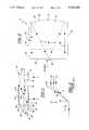
- FIG. 1is a top plan view of a hologram display according to one embodiment of the invention.
- FIG. 2is a front elevational view of the display shown in FIG. 1;
- FIG. 3schematically illustrates a prior art arrangement of a hologram and grating to form an achromatic system
- FIG. 4illustrates an alternate embodiment according to the invention incorporating an angled transmission grating
- FIG. 5is a schematic view illustrating the angles of incidence and refraction for the embodiment shown in FIG. 1;
- FIG. 6is a schematic view illustrating the recording system for the hologram in FIG. 1;
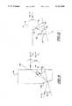
- FIG. 7illustrates an alternate hologram display using edge illumination and internal beam expansion
- FIG. 8illustrates an alternate hologram display using multiple internal reflections
- FIG. 9illustrates an alternate display using an angles reflective edge surface to reflect the beam directly to the hologram
- FIG. 10illustrates an alternate display of a laser diode coupled to the hologram via optical fiber
- FIG. 11discloses an alternate hologram display having an opposing edge surface collimating the beam and reflecting the beam toward the hologram.
- FIG. 1 and FIG. 2illustrate a monolithic hologram display system 10.
- the system 10includes a developed photographic planar plate 12 having a developed emulsion (i.e. hologram) 14 at its back side 15.
- the photographic plate 12is mounted onto a planar front surface 18 of a solid glass cover plate 16.
- the plates 12 and 16abut each other and have similar indexes of refraction.
- An optical cementis between the two plates 12 and 16 such that no air gap exists between the two plates.
- the optical cementhas an index of refraction equal to or higher than the index of refraction for plate 16.
- the solid glass cover plate 16has a planar rear surface 20 parallel to the front surface 18 and a plurality of side edge surfaces 22, 24, 26, 28 and 30 between the front surface 18 and rear surface 20.
- a laser diode 32is mounted directly on edge surface 22 such that the reconstructive light beam 34 from the laser diode is directed into glass plate 16 through edge surface 22.
- Laser diode 32can be powered by batteries to achieve complete portability of the display system 10.
- the laser diodedesirably has a volume of less than a few cubic millimeters. Its power consumption is usually less than 1 watt and has an operating voltage under 5 volts.
- the beam 34 that emanates from the laser diodediverges in a non-circular, elongated pattern such that the divergence shown in FIG. 2 parallel to the front surface 18 is substantially greater than the divergence transverse to the front surface 18 shown in FIG. 1.
- the ratios between the two rates of divergingcan be as large as five to one.
- the diverging beam 34is reflected off of contoured edge surface 24.
- Edge surface 24has a reflective coating 36 adhered thereto.
- the edge surface 24is contoured in both the vertical direction as shown in FIG. 2 and the horizontal direction as shown in FIG. 1 to collimate the diverging beam 34 to form collimated beam leg 38.
- Collimated beam leg 38is directed parallel to front surface 20 toward edge surface 26 which is adjacent to the rear of edge surface 22. Furthermore, edge surface 26 is canted with respect to both the edge surface 22 and front surface 18. The edge surface 26 has a reflection grating 40 thereon which both reflects and diffracts the beam leg 38.
- the last leg 39 of beam 34is directed to pass surface 18, through the optical cement and to the photographic plate 12 through the hologram 14 to reconstruct a virtual or real image.
- the hologramis a transmission hologram that is observed from the plate glass 12 (viewed from below as shown in FIG. 1). However, the hologram can alternatively be a reflection hologram and can be viewed from the side with the glass plate 16 (viewed from above as shown in FIG. 1).
- a conventional achromatic grating system 41is illustrated in FIG. 3.
- a transmission grating 43is parallel to a hologram 45.
- the frequency of the grating and the carrier frequency of the hologramare equal to produce achromaticity between two wavelengths ⁇ 1 and ⁇ 2 which are slightly longer and shorter respectively about a predetermined measured wavelength ⁇ .
- the two different wavelengths ⁇ 1 and ⁇ 2are both diffracted a different degree through the grating and then are diffracted through the hologram such that the exit angles of ⁇ 1 and ⁇ 2 are equal and therefore the chromatic dispersion is greatly reduced or eliminated between the two different wavelengths.
- the gratingmust be spatially displaced from the hologram in both a longitudinal and lateral direction.
- the gratingmust be at least as large as the hologram.
- the gratingby being as large as the hologram and spaced behind the hologram, must be laterally displaced a significant amount from the hologram. Consequently, a relatively large display apparatus is needed.
- FIG. 4An alternate arrangement 44 shown in FIG. 4 illustrates the angles of incidence and diffraction of the light beam with the transmission grating 43a and the hologram transmission 14a.
- the grating planeis canted with respect to the plane of the hologram 4a. The relationship is as follows:
- fis the carrier frequency of the hologram
- ⁇is the wavelength of the light beam
- ⁇ 1is the angle incidence
- ⁇ 2is the angle of diffraction (i.e. exit angle).
- a further reduction of space for displaying the hologramcan be achieved if the transmission grating 43a is replaced by the aforementioned reflection grating 40.
- ⁇ 4is chosen to match the required incident angle ⁇ 1 of the hologram at ⁇ 0 .
- the tilt of angle of the grating 40is selected to satisfy Equation 7 for the geometry where the incident beam leg 38 is substantially parallel to hologram 14. The following four equations must be satisfied.
- Equation (7)The derivatives in Equation (7) are substituted by terms in Equation 3 and Equation 5, to obtain: ##EQU8## Equation 12 has ⁇ 3 substituted by terms found in Equation 10 to obtain: ##EQU9## A desired ⁇ 1 is selected and the required angle ⁇ 4 is thus calculated.
- the hologram of FIG. 1is produced by a laser light beam 60 aimed toward a beam splitter 62 which splits beam 60 into two beams 64 and 74.
- Beam 64passes through a lens 66 to produce a diverging beam leg 68 which impinges on an object 70.
- An object wavefront 72reflects off object 70 situated to the left of the hologram assembly 10. The wavefront 72 is then directed through the glass plate 16 to impinge upon an emulsion layer 13.
- the second beam 74is reflected off mirror 76 and through a focusing lens 78 which focuses the beam at point 80 at the edge surface 22.
- the lens 78can be astigmatic to achieve a proper beam spread within the glass plate in the vertical and horizontal directions.
- the beam 74is reflected off mirrored coating 36 on contoured edge 24 to produce the collimated beam leg 82 which in turn is reflected off of reflection grating 26 such that a reference wavefront 84 is directed onto the emulsion 13.
- An optical coupling liquidis interposed between the plates 12 and 16 to fill up the space therebetween.
- the liquidhas an index of refraction equal to or slightly higher than the glass plates 12 and 16. If a reflection hologram is being produced, the object 70 will be placed to the right of plate 12 and the beams 64 and 68 are similarly directed to the right to impinge on object 70 to form an object wavefront 72 impinging on plate 12 from the right.
- the hologram plate 12is taken off plate 16 and the emulsion 13 is then processed to form hologram 14.
- the processed plate 12is remounted on plate 16 with optical cement for display of the hologram.
- the path of the reference beam 74 within the glass plate 16 shown in FIG. 6is duplicated by the path of beam 34 when it reconstructs the image of the object 70 shown in FIG. 1.
- laser diode 32is mounted on side edge surface 22b near the rear surface 20 of glass plate 16b.
- the opposing side edge surface 24bhas a reflective coating 36b.
- the edge surface 24bis flat so that the beam 34b continues to diverge along its leg 38b after reflection off of edge surface 24b until it impinges hologram 14. For certain applications, this simplified geometric arrangement is adequate with the diverging beam 38 impinging upon hologram 14.
- the laser diode 32is mounted near a front portion of edge surface 22c adjacent the hologram 14.
- the diode 32has a beam 32c arranged such that it is internally reflected off the back surface 20 of the plate 16c.
- the angle of incidence of beam surface 20is sufficiently great to satisfy Snell's equation for complete internal reflection. Therefore, total internal reflection occurs without the need for a reflective coating on back surface 20.
- Edge surface 24chas a reflective coating thereon.
- Edge surface 24cis flat, such that the leg 39c of beam 34 continues to diverge after reflection off edge surface 24c until it impinges upon the hologram 14.
- FIG. 9Another embodiment illustrated in FIG. 9 discloses a laser diode 32 mounted at the center of the edge 22d.
- the opposing edge surface 24dis angled such that it directs diverging beam leg 38d toward the hologram 14 at the front surface 18d.
- FIG. 10discloses an arrangement and geometry which provides for longer beam travel within the glass plate.
- the laser diode 32eis remotely positioned from the edge surface 22e and is optically coupled thereto by an optical fiber 50 mounted at entrance point 52.
- the entrance point 52is located near the front surface 18e.
- the beam 34ediverges from the entrance point 52 and is aimed directly at edge surface 24e at an angle toward the rear surface 20e.
- the beamis reflected by reflective coating 36e on edge surface 24e onto the rear surface 20e. Total internal reflection off of rear surface 20e then redirects the beam back toward edge surface 22e.
- Edge surface 22ehas a reflective coating thereon except for a transparent window 54 at the entrance point 52.
- the incident beamis then reflected off of edge surface 22e and directed toward hologram 14.
- the beamis reflected off of three surfaces within the glass plate before it impinges on hologram 14.
- the beam 34ealso travels farther, thus its diverging angle is smaller than the one shown in FIG. 9.
- FIG. 11discloses an arrangement which has the laser diode 32f mounted on side edge surface 22f near the front surface 18f.
- the beam 34fis directed to edge surface 24f.
- Edge 24fis both angled and contoured such that the beam leg 38f is both collimated and directed toward the hologram 14 as it reflects off of edge surface 24f.
- the arrangement of the hologram recording system as illustrated in FIG. 6is modified such that reference beam 74 is reflected off mirror 76 and through lens 78 to focus on the side edge surface 22 and pass into and diverge in the hologram assembly to duplicate the same path as illustrated in FIGS. 7-11.
- the emulsion 13 and derived processed hologram 14can also be applied or coated directly on plate 16 thereby eliminating photographic plate 12.
Landscapes
- Physics & Mathematics (AREA)
- General Physics & Mathematics (AREA)
- Optics & Photonics (AREA)
- Diffracting Gratings Or Hologram Optical Elements (AREA)
- Holo Graphy (AREA)
Abstract
Description
λ f.sub.1 =sin θ.sub.2 +sin θ.sub.1 (1)
λf.sub.2 =sin θ.sub.3 +sin θ.sub.4 (4)
θ.sub.3 -θ.sub.4 =90°-θ.sub.1 (10)
λ.sub.0 f.sub.1 =sin θ.sub.1 (11)
λ.sub.0 f.sub.2 =sin θ.sub.3 +sin θ.sub.4(4)
Claims (24)
Priority Applications (1)
| Application Number | Priority Date | Filing Date | Title |
|---|---|---|---|
| US07/627,984US5151800A (en) | 1990-12-17 | 1990-12-17 | Compact hologram displays & method of making compact hologram |
Applications Claiming Priority (1)
| Application Number | Priority Date | Filing Date | Title |
|---|---|---|---|
| US07/627,984US5151800A (en) | 1990-12-17 | 1990-12-17 | Compact hologram displays & method of making compact hologram |
Publications (1)
| Publication Number | Publication Date |
|---|---|
| US5151800Atrue US5151800A (en) | 1992-09-29 |
Family
ID=24516931
Family Applications (1)
| Application Number | Title | Priority Date | Filing Date |
|---|---|---|---|
| US07/627,984Expired - LifetimeUS5151800A (en) | 1990-12-17 | 1990-12-17 | Compact hologram displays & method of making compact hologram |
Country Status (1)
| Country | Link |
|---|---|
| US (1) | US5151800A (en) |
Cited By (24)
| Publication number | Priority date | Publication date | Assignee | Title |
|---|---|---|---|---|
| US5293259A (en)* | 1992-12-07 | 1994-03-08 | The University Of Alabama In Hunstville | Integrated rainbow hologram |
| WO1995004294A3 (en)* | 1993-07-21 | 1995-03-30 | Imedge Technology Inc | Holograms and light panels |
| US5455693A (en)* | 1992-09-24 | 1995-10-03 | Hughes Aircraft Company | Display hologram |
| WO1995031740A1 (en)* | 1994-05-17 | 1995-11-23 | Environmental Research Institute Of Michigan | Compact holographic sight |
| WO1997043672A1 (en)* | 1996-05-10 | 1997-11-20 | John Scott Strachan | Holographic coaching |
| EP0704721A3 (en)* | 1994-09-27 | 1997-12-17 | AT&T Corp. | Methods and apparatus for generating and displaying holographic images utilizing a laser pointer |
| US5710645A (en)* | 1993-01-29 | 1998-01-20 | Imedge Technology, Inc. | Grazing incidence holograms and system and method for producing the same |
| US5815936A (en)* | 1994-05-17 | 1998-10-06 | Environmental Research Institute Of Michigan | Detachable hologram assembly and windage/elevation adjuster for a compact holographic sight |
| US5822089A (en)* | 1993-01-29 | 1998-10-13 | Imedge Technology Inc. | Grazing incidence holograms and system and method for producing the same |
| US5854697A (en)* | 1991-11-12 | 1998-12-29 | The University Of Alabama In Huntsville | Waveguide hologram illuminators |
| US5877874A (en)* | 1995-08-24 | 1999-03-02 | Terrasun L.L.C. | Device for concentrating optical radiation |
| US6266473B1 (en) | 1997-02-07 | 2001-07-24 | Alliedsignal Inc. | Reflective display |
| US6274860B1 (en) | 1999-05-28 | 2001-08-14 | Terrasun, Llc | Device for concentrating optical radiation |
| US6407833B2 (en)* | 1999-02-16 | 2002-06-18 | Zebra Imaging, Inc. | System and method for producing and displaying a one-step, edge-lit hologram |
| US20020163679A1 (en)* | 2001-05-04 | 2002-11-07 | Samsung Electronics Co., Ltd. | Hologram recording method using beam with very large incident angle, hologram reproduction apparatus using holographic reflector and sologram reproduction method using the same, and flat display element apparatus using holographic reflector |
| US6490060B1 (en) | 1999-10-14 | 2002-12-03 | Eotech, Inc. | Lightweight holographic sight |
| US20030063388A1 (en)* | 2001-09-12 | 2003-04-03 | Arthur Berman | Method and apparatus for configuration and assembly of a video projection light management system |
| US20050057808A1 (en)* | 2003-09-12 | 2005-03-17 | Lasermax, Inc. | Diffractive head up display for firearms |
| US20080117341A1 (en)* | 2006-11-11 | 2008-05-22 | Vuzix Corporation | Traveling lens for video display |
| WO2017002124A1 (en)* | 2015-07-02 | 2017-01-05 | Evgeny Stolov | Improved optical aiming device |
| US20180094791A1 (en)* | 2016-10-05 | 2018-04-05 | Samsung Display Co., Ltd. | Backlight unit and holographic display device including the same |
| US20180173057A1 (en)* | 2016-12-21 | 2018-06-21 | Samsung Electronics Co., Ltd. | Backlight unit and holographic display device including the same |
| US10247515B2 (en) | 2015-06-26 | 2019-04-02 | Ziel Optics, Inc. | Holographic sight with optimized reflection and image angles |
| CN112596252A (en)* | 2020-12-30 | 2021-04-02 | 南开大学 | Light beam drift compensation device without mechanical structure and implementation method thereof |
Citations (7)
| Publication number | Priority date | Publication date | Assignee | Title |
|---|---|---|---|---|
| US3680943A (en)* | 1970-12-22 | 1972-08-01 | Ibm | Holographic imaging having improved resolution and intensity by synthetically enlarging the aperture |
| US4012150A (en)* | 1975-08-18 | 1977-03-15 | Environmental Research Institute Of Michigan | Holographic light line sight |
| US4223975A (en)* | 1978-09-25 | 1980-09-23 | Environmental Research Institute Of Michigan | Aberration correction of magnified holographic images |
| US4314283A (en)* | 1980-09-02 | 1982-02-02 | Xerox Corporation | Diffraction based light collector |
| US4643515A (en)* | 1985-04-01 | 1987-02-17 | Environmental Research Institute Of Michigan | Method and apparatus for recording and displaying edge-illuminated holograms |
| US4737001A (en)* | 1987-01-06 | 1988-04-12 | Hughes Aircraft Company | Holographic indicator for determining vehicle perimeter |
| US5035473A (en)* | 1988-05-25 | 1991-07-30 | Canon Kabushiki Kaisha | Display apparatus |
- 1990
- 1990-12-17USUS07/627,984patent/US5151800A/ennot_activeExpired - Lifetime
Patent Citations (7)
| Publication number | Priority date | Publication date | Assignee | Title |
|---|---|---|---|---|
| US3680943A (en)* | 1970-12-22 | 1972-08-01 | Ibm | Holographic imaging having improved resolution and intensity by synthetically enlarging the aperture |
| US4012150A (en)* | 1975-08-18 | 1977-03-15 | Environmental Research Institute Of Michigan | Holographic light line sight |
| US4223975A (en)* | 1978-09-25 | 1980-09-23 | Environmental Research Institute Of Michigan | Aberration correction of magnified holographic images |
| US4314283A (en)* | 1980-09-02 | 1982-02-02 | Xerox Corporation | Diffraction based light collector |
| US4643515A (en)* | 1985-04-01 | 1987-02-17 | Environmental Research Institute Of Michigan | Method and apparatus for recording and displaying edge-illuminated holograms |
| US4737001A (en)* | 1987-01-06 | 1988-04-12 | Hughes Aircraft Company | Holographic indicator for determining vehicle perimeter |
| US5035473A (en)* | 1988-05-25 | 1991-07-30 | Canon Kabushiki Kaisha | Display apparatus |
Non-Patent Citations (6)
| Title |
|---|
| Applied Optics, vol. 25, No. 22, Nov. 15, 1986, Article entitled "Display of Ordinary Transmission Holograms with a White Light Source" by Boj, Pardo, and Quintana. |
| Applied Optics, vol. 25, No. 22, Nov. 15, 1986, Article entitled Display of Ordinary Transmission Holograms with a White Light Source by Boj, Pardo, and Quintana.* |
| Optical Society of America, Apr. 7, 1970, p. 714, Paper entitled "Edge-Illuminated Hologram" by L. H. Lin. |
| Optical Society of America, Apr. 7, 1970, p. 714, Paper entitled Edge Illuminated Hologram by L. H. Lin.* |
| Practical holography IV(1990), vol. 1212, Article entitled "Edge-Lit Rainbow Holograms" by Benton, Birner, & Shirakura. |
| Practical holography IV(1990), vol. 1212, Article entitled Edge Lit Rainbow Holograms by Benton, Birner, & Shirakura.* |
Cited By (45)
| Publication number | Priority date | Publication date | Assignee | Title |
|---|---|---|---|---|
| US5854697A (en)* | 1991-11-12 | 1998-12-29 | The University Of Alabama In Huntsville | Waveguide hologram illuminators |
| US5455693A (en)* | 1992-09-24 | 1995-10-03 | Hughes Aircraft Company | Display hologram |
| US5293259A (en)* | 1992-12-07 | 1994-03-08 | The University Of Alabama In Hunstville | Integrated rainbow hologram |
| US5710645A (en)* | 1993-01-29 | 1998-01-20 | Imedge Technology, Inc. | Grazing incidence holograms and system and method for producing the same |
| US5822089A (en)* | 1993-01-29 | 1998-10-13 | Imedge Technology Inc. | Grazing incidence holograms and system and method for producing the same |
| WO1995004294A3 (en)* | 1993-07-21 | 1995-03-30 | Imedge Technology Inc | Holograms and light panels |
| WO1995031740A1 (en)* | 1994-05-17 | 1995-11-23 | Environmental Research Institute Of Michigan | Compact holographic sight |
| US5483362A (en)* | 1994-05-17 | 1996-01-09 | Environmental Research Institute Of Michigan | Compact holographic sight |
| US5815936A (en)* | 1994-05-17 | 1998-10-06 | Environmental Research Institute Of Michigan | Detachable hologram assembly and windage/elevation adjuster for a compact holographic sight |
| EP0704721A3 (en)* | 1994-09-27 | 1997-12-17 | AT&T Corp. | Methods and apparatus for generating and displaying holographic images utilizing a laser pointer |
| US5877874A (en)* | 1995-08-24 | 1999-03-02 | Terrasun L.L.C. | Device for concentrating optical radiation |
| WO1997043672A1 (en)* | 1996-05-10 | 1997-11-20 | John Scott Strachan | Holographic coaching |
| US6266473B1 (en) | 1997-02-07 | 2001-07-24 | Alliedsignal Inc. | Reflective display |
| US6407833B2 (en)* | 1999-02-16 | 2002-06-18 | Zebra Imaging, Inc. | System and method for producing and displaying a one-step, edge-lit hologram |
| US6274860B1 (en) | 1999-05-28 | 2001-08-14 | Terrasun, Llc | Device for concentrating optical radiation |
| US6490060B1 (en) | 1999-10-14 | 2002-12-03 | Eotech, Inc. | Lightweight holographic sight |
| US20020163679A1 (en)* | 2001-05-04 | 2002-11-07 | Samsung Electronics Co., Ltd. | Hologram recording method using beam with very large incident angle, hologram reproduction apparatus using holographic reflector and sologram reproduction method using the same, and flat display element apparatus using holographic reflector |
| US7573623B2 (en) | 2001-05-04 | 2009-08-11 | Samsung Electronics Co., Ltd. | Hologram recording method using beam with very large incident angle, hologram reproduction apparatus using holographic reflector and hologram reproduction method using the same, and flat display element apparatus using holographic reflector |
| EP1255173A3 (en)* | 2001-05-04 | 2004-08-04 | Samsung Electronics Co., Ltd. | Hologram recording method using beam with very large incident angle |
| US6842273B2 (en) | 2001-05-04 | 2005-01-11 | Samsung Electronics Co., Ltd. | Hologram recording method using beam with very large incident angle, hologram reproduction apparatus using holographic reflector and sologram reproduction method using the same, and flat display element apparatus using holographic reflector |
| US20050105151A1 (en)* | 2001-05-04 | 2005-05-19 | Samsung Electronics Co., Ltd. | Hologram recording method using beam with very large incident angle, hologram reproduction apparatus using holographic reflector and hologram reproduction method using the same, and flat display element apparatus using holographic reflector |
| US6999237B2 (en)* | 2001-09-12 | 2006-02-14 | Lightmaster Systems, Inc. | Method and apparatus for configuration and assembly of a video projection light management system |
| US20030063388A1 (en)* | 2001-09-12 | 2003-04-03 | Arthur Berman | Method and apparatus for configuration and assembly of a video projection light management system |
| US20080062487A1 (en)* | 2003-09-12 | 2008-03-13 | Lasermax, Inc. | Head up display for firearms |
| US20060236585A1 (en)* | 2003-09-12 | 2006-10-26 | Lasermax, Inc. | Method of Sighting a Firearm with a Diffractive Head Up Display |
| US7454860B2 (en)* | 2003-09-12 | 2008-11-25 | Lasermax, Inc. | Method of sighting a firearm with a diffractive head up display |
| US7069685B2 (en) | 2003-09-12 | 2006-07-04 | Lasermax, Inc. | Diffractive head up display for firearms |
| US7721481B2 (en) | 2003-09-12 | 2010-05-25 | Lasermax, Inc. | Head up display for firearms |
| US20050057808A1 (en)* | 2003-09-12 | 2005-03-17 | Lasermax, Inc. | Diffractive head up display for firearms |
| US20080117341A1 (en)* | 2006-11-11 | 2008-05-22 | Vuzix Corporation | Traveling lens for video display |
| US8139103B2 (en)* | 2006-11-11 | 2012-03-20 | Vuzix Corporation | Traveling lens for video display |
| US10247515B2 (en) | 2015-06-26 | 2019-04-02 | Ziel Optics, Inc. | Holographic sight with optimized reflection and image angles |
| US20180149448A1 (en)* | 2015-07-02 | 2018-05-31 | Evgeny Stolov | Improved optical aiming device |
| WO2017002124A1 (en)* | 2015-07-02 | 2017-01-05 | Evgeny Stolov | Improved optical aiming device |
| US10753706B2 (en) | 2015-07-02 | 2020-08-25 | Evgeny Stolov | Optical aiming device |
| US20180094791A1 (en)* | 2016-10-05 | 2018-04-05 | Samsung Display Co., Ltd. | Backlight unit and holographic display device including the same |
| CN107918269A (en)* | 2016-10-05 | 2018-04-17 | 三星显示有限公司 | Backlight unit and holographic display device including same |
| US10711972B2 (en)* | 2016-10-05 | 2020-07-14 | Samsung Display Co., Ltd. | Backlight unit and holographic display device including the same |
| KR20180038101A (en)* | 2016-10-05 | 2018-04-16 | 삼성디스플레이 주식회사 | Backlilght unit and holographic display device comprising the same |
| CN107918269B (en)* | 2016-10-05 | 2021-06-01 | 三星显示有限公司 | Backlight unit and holographic display device including the same |
| US20180173057A1 (en)* | 2016-12-21 | 2018-06-21 | Samsung Electronics Co., Ltd. | Backlight unit and holographic display device including the same |
| KR20180072356A (en)* | 2016-12-21 | 2018-06-29 | 삼성전자주식회사 | Backlight unit and three-dimensional image display apparatus including the same |
| US10459288B2 (en)* | 2016-12-21 | 2019-10-29 | Samsung Electronics Co., Ltd. | Backlight unit and holographic display device including the same |
| CN112596252A (en)* | 2020-12-30 | 2021-04-02 | 南开大学 | Light beam drift compensation device without mechanical structure and implementation method thereof |
| CN112596252B (en)* | 2020-12-30 | 2023-02-24 | 南开大学 | A beam drift compensation device without mechanical structure and its realization method |
Similar Documents
| Publication | Publication Date | Title |
|---|---|---|
| US5151800A (en) | Compact hologram displays & method of making compact hologram | |
| US5515184A (en) | Waveguide hologram illuminators | |
| EP0746783B1 (en) | Holographic optical devices | |
| US5682255A (en) | Holographic optical devices for the transmission of optical signals of a plurality of channels | |
| US5892599A (en) | Miniature fingerprint sensor using a trapezoidal prism and a holographic optical element | |
| EP0405540B1 (en) | Dispersion-compensated windshield hologram virtual image display | |
| US4671603A (en) | Optical filters and multiplexing-demultiplexing devices using the same | |
| CN113835145B (en) | Holographic grating manufacturing device, holographic grating and two-dimensional holographic grating optical waveguide | |
| US5071210A (en) | Sandwich reflection hologram | |
| US5935507A (en) | Multi-point laser trapping device and the method thereof | |
| AU3052499A (en) | Holographic optical devices | |
| US4735486A (en) | Systems and methods for processing optical correlator memory devices | |
| Benton et al. | Edge-lit rainbow holograms | |
| US11262163B2 (en) | Holographic weapon sight with parabolic reflector | |
| US5124815A (en) | Method for forming holographic optical elements free of secondary fringes | |
| KR102809311B1 (en) | Hologram waveguiding | |
| US3754808A (en) | Holographic readout system employing predispersion diffraction grating | |
| CN112327587A (en) | Holographic projector | |
| KR900018925A (en) | Wedge Prism Assembly for Optical Information Storage | |
| US20050195456A1 (en) | Artificial star generation apparatus and method for telescope systems | |
| US4978183A (en) | Holographic optic element collimator and method and apparatus for manufacture | |
| US3558207A (en) | Hologram system employing incoherent light | |
| US5071208A (en) | Two beam method for forming holographic optical elements free of secondary fringes | |
| WO1999009514A1 (en) | A miniature fingerprint sensor using a trapezoidal prism and a holographic optical element | |
| US5015049A (en) | Method of forming holographic optical elements free of secondary fringes |
Legal Events
| Date | Code | Title | Description |
|---|---|---|---|
| AS | Assignment | Owner name:ENVIRONMENTAL RESEARCH INSTITUTE OF MICHIGAN, ANN Free format text:ASSIGNMENT OF ASSIGNORS INTEREST.;ASSIGNOR:UPATNIEKS, JURIS;REEL/FRAME:005545/0589 Effective date:19901210 | |
| STCF | Information on status: patent grant | Free format text:PATENTED CASE | |
| FEPP | Fee payment procedure | Free format text:PAYOR NUMBER ASSIGNED (ORIGINAL EVENT CODE: ASPN); ENTITY STATUS OF PATENT OWNER: LARGE ENTITY | |
| FEPP | Fee payment procedure | Free format text:PAYOR NUMBER ASSIGNED (ORIGINAL EVENT CODE: ASPN); ENTITY STATUS OF PATENT OWNER: LARGE ENTITY Free format text:PAYER NUMBER DE-ASSIGNED (ORIGINAL EVENT CODE: RMPN); ENTITY STATUS OF PATENT OWNER: LARGE ENTITY | |
| REMI | Maintenance fee reminder mailed | ||
| FPAY | Fee payment | Year of fee payment:4 | |
| SULP | Surcharge for late payment | ||
| AS | Assignment | Owner name:ERIM INTERNATIONAL, INC., MICHIGAN Free format text:CONFIRMATORY ASSIGNMENT;ASSIGNOR:ENVIRONMENTAL RESEARCH INSTITUTE OF MICHIGAN;REEL/FRAME:010018/0259 Effective date:19990811 | |
| FEPP | Fee payment procedure | Free format text:PAT HLDR NO LONGER CLAIMS SMALL ENT STAT AS NONPROFIT ORG (ORIGINAL EVENT CODE: LSM3); ENTITY STATUS OF PATENT OWNER: LARGE ENTITY | |
| AS | Assignment | Owner name:FIRST UNION NATIONAL BANK, NORTH CAROLINA Free format text:GUARANTOR SECURITY AGREEMENT;ASSIGNOR:ERIM INTERNATIONAL, INC.;REEL/FRAME:010395/0907 Effective date:19990903 | |
| REMI | Maintenance fee reminder mailed | ||
| FPAY | Fee payment | Year of fee payment:8 | |
| SULP | Surcharge for late payment | ||
| AS | Assignment | Owner name:WACHOVIA BANK, NATIONAL, NORTH CAROLINA Free format text:ASSIGNMENT OF SECURITY INTEREST;ASSIGNOR:VERIDIAN SYSTEMS DIVISION, INC.;REEL/FRAME:012991/0435 Effective date:20020610 | |
| AS | Assignment | Owner name:VERIDIAN SYSTEMS DIVISION, INC., VIRGINIA Free format text:SATISFACTION OF COLLATERAL AGREEMENT/TERMINATION OF SECURITY INTEREST;ASSIGNOR:WACHOVIA BANK, NATIONAL ASSOCIATION;REEL/FRAME:014420/0009 Effective date:20030811 | |
| FPAY | Fee payment | Year of fee payment:12 | |
| AS | Assignment | Owner name:ERIM INTERNATIONAL, INC., MICHIGAN Free format text:SECURITY INTEREST;ASSIGNOR:WACHOVIA BANK, NATIONAL ASSOCIATION;REEL/FRAME:017105/0462 Effective date:20051019 |