US5151026A - Apparatus for removing liquids from solids - Google Patents
Apparatus for removing liquids from solidsDownload PDFInfo
- Publication number
- US5151026A US5151026AUS07/606,561US60656190AUS5151026AUS 5151026 AUS5151026 AUS 5151026AUS 60656190 AUS60656190 AUS 60656190AUS 5151026 AUS5151026 AUS 5151026A
- Authority
- US
- United States
- Prior art keywords
- screw
- forces
- liquid
- barrel
- water
- Prior art date
- Legal status (The legal status is an assumption and is not a legal conclusion. Google has not performed a legal analysis and makes no representation as to the accuracy of the status listed.)
- Expired - Lifetime
Links
- 239000007788liquidSubstances0.000titleclaimsabstractdescription36
- 239000007787solidSubstances0.000titledescription3
- 239000000463materialSubstances0.000claimsabstractdescription115
- 238000000605extractionMethods0.000claimsabstractdescription33
- 238000011144upstream manufacturingMethods0.000claimsdescription9
- XLYOFNOQVPJJNP-UHFFFAOYSA-NwaterSubstancesOXLYOFNOQVPJJNP-UHFFFAOYSA-N0.000description63
- 238000000034methodMethods0.000description16
- 239000004033plasticSubstances0.000description13
- 229920003023plasticPolymers0.000description13
- 239000004793PolystyreneSubstances0.000description11
- 229920002223polystyrenePolymers0.000description11
- 229920001971elastomerPolymers0.000description8
- 229920006327polystyrene foamPolymers0.000description8
- 230000000694effectsEffects0.000description7
- 239000008188pelletSubstances0.000description6
- 239000005060rubberSubstances0.000description6
- 235000013305foodNutrition0.000description5
- 239000000126substanceSubstances0.000description4
- 238000005406washingMethods0.000description4
- 238000010438heat treatmentMethods0.000description3
- 239000011295pitchSubstances0.000description3
- 239000013502plastic wasteSubstances0.000description3
- 229920000642polymerPolymers0.000description3
- 239000002002slurrySubstances0.000description3
- 239000002904solventSubstances0.000description3
- 239000002699waste materialSubstances0.000description3
- 229920002209Crumb rubberPolymers0.000description2
- 238000004140cleaningMethods0.000description2
- 239000000806elastomerSubstances0.000description2
- 235000013410fast foodNutrition0.000description2
- 230000033001locomotionEffects0.000description2
- 238000004519manufacturing processMethods0.000description2
- 238000002844meltingMethods0.000description2
- 230000008018meltingEffects0.000description2
- 229920005615natural polymerPolymers0.000description2
- 238000009877renderingMethods0.000description2
- 229920001059synthetic polymerPolymers0.000description2
- 239000002023woodSubstances0.000description2
- 241001661918BartoniaSpecies0.000description1
- 229920001131Pulp (paper)Polymers0.000description1
- 241000244177Strongyloides stercoralisSpecies0.000description1
- 238000010521absorption reactionMethods0.000description1
- 239000000969carrierSubstances0.000description1
- 238000002485combustion reactionMethods0.000description1
- 238000011109contaminationMethods0.000description1
- 238000001816coolingMethods0.000description1
- 230000002079cooperative effectEffects0.000description1
- 230000002939deleterious effectEffects0.000description1
- 238000010586diagramMethods0.000description1
- 238000006073displacement reactionMethods0.000description1
- 229920006248expandable polystyrenePolymers0.000description1
- 238000001125extrusionMethods0.000description1
- 230000010006flightEffects0.000description1
- -1flocked latexesPolymers0.000description1
- 239000006260foamSubstances0.000description1
- 239000011344liquid materialSubstances0.000description1
- 230000001473noxious effectEffects0.000description1
- 239000002245particleSubstances0.000description1
- 239000011236particulate materialSubstances0.000description1
- 238000004064recyclingMethods0.000description1
- 238000001179sorption measurementMethods0.000description1
- 230000008016vaporizationEffects0.000description1
- 239000011345viscous materialSubstances0.000description1
- 238000003809water extractionMethods0.000description1
Images

Classifications
- B—PERFORMING OPERATIONS; TRANSPORTING
- B30—PRESSES
- B30B—PRESSES IN GENERAL
- B30B9/00—Presses specially adapted for particular purposes
- B30B9/02—Presses specially adapted for particular purposes for squeezing-out liquid from liquid-containing material, e.g. juice from fruits, oil from oil-containing material
- B30B9/12—Presses specially adapted for particular purposes for squeezing-out liquid from liquid-containing material, e.g. juice from fruits, oil from oil-containing material using pressing worms or screws co-operating with a permeable casing
- B—PERFORMING OPERATIONS; TRANSPORTING
- B29—WORKING OF PLASTICS; WORKING OF SUBSTANCES IN A PLASTIC STATE IN GENERAL
- B29B—PREPARATION OR PRETREATMENT OF THE MATERIAL TO BE SHAPED; MAKING GRANULES OR PREFORMS; RECOVERY OF PLASTICS OR OTHER CONSTITUENTS OF WASTE MATERIAL CONTAINING PLASTICS
- B29B15/00—Pretreatment of the material to be shaped, not covered by groups B29B7/00 - B29B13/00
- B29B15/02—Pretreatment of the material to be shaped, not covered by groups B29B7/00 - B29B13/00 of crude rubber, gutta-percha, or similar substances
- B29B15/06—Washing devices
- B—PERFORMING OPERATIONS; TRANSPORTING
- B29—WORKING OF PLASTICS; WORKING OF SUBSTANCES IN A PLASTIC STATE IN GENERAL
- B29C—SHAPING OR JOINING OF PLASTICS; SHAPING OF MATERIAL IN A PLASTIC STATE, NOT OTHERWISE PROVIDED FOR; AFTER-TREATMENT OF THE SHAPED PRODUCTS, e.g. REPAIRING
- B29C48/00—Extrusion moulding, i.e. expressing the moulding material through a die or nozzle which imparts the desired form; Apparatus therefor
- B29C48/03—Extrusion moulding, i.e. expressing the moulding material through a die or nozzle which imparts the desired form; Apparatus therefor characterised by the shape of the extruded material at extrusion
- B29C48/04—Particle-shaped
- B—PERFORMING OPERATIONS; TRANSPORTING
- B29—WORKING OF PLASTICS; WORKING OF SUBSTANCES IN A PLASTIC STATE IN GENERAL
- B29C—SHAPING OR JOINING OF PLASTICS; SHAPING OF MATERIAL IN A PLASTIC STATE, NOT OTHERWISE PROVIDED FOR; AFTER-TREATMENT OF THE SHAPED PRODUCTS, e.g. REPAIRING
- B29C48/00—Extrusion moulding, i.e. expressing the moulding material through a die or nozzle which imparts the desired form; Apparatus therefor
- B29C48/25—Component parts, details or accessories; Auxiliary operations
- B29C48/36—Means for plasticising or homogenising the moulding material or forcing it through the nozzle or die
- B29C48/395—Means for plasticising or homogenising the moulding material or forcing it through the nozzle or die using screws surrounded by a cooperating barrel, e.g. single screw extruders
- B29C48/40—Means for plasticising or homogenising the moulding material or forcing it through the nozzle or die using screws surrounded by a cooperating barrel, e.g. single screw extruders using two or more parallel screws or at least two parallel non-intermeshing screws, e.g. twin screw extruders
- B29C48/405—Intermeshing co-rotating screws
- B—PERFORMING OPERATIONS; TRANSPORTING
- B29—WORKING OF PLASTICS; WORKING OF SUBSTANCES IN A PLASTIC STATE IN GENERAL
- B29C—SHAPING OR JOINING OF PLASTICS; SHAPING OF MATERIAL IN A PLASTIC STATE, NOT OTHERWISE PROVIDED FOR; AFTER-TREATMENT OF THE SHAPED PRODUCTS, e.g. REPAIRING
- B29C48/00—Extrusion moulding, i.e. expressing the moulding material through a die or nozzle which imparts the desired form; Apparatus therefor
- B29C48/25—Component parts, details or accessories; Auxiliary operations
- B29C48/36—Means for plasticising or homogenising the moulding material or forcing it through the nozzle or die
- B29C48/50—Details of extruders
- B29C48/505—Screws
- B29C48/535—Screws with thread pitch varying along the longitudinal axis
- B—PERFORMING OPERATIONS; TRANSPORTING
- B29—WORKING OF PLASTICS; WORKING OF SUBSTANCES IN A PLASTIC STATE IN GENERAL
- B29C—SHAPING OR JOINING OF PLASTICS; SHAPING OF MATERIAL IN A PLASTIC STATE, NOT OTHERWISE PROVIDED FOR; AFTER-TREATMENT OF THE SHAPED PRODUCTS, e.g. REPAIRING
- B29C48/00—Extrusion moulding, i.e. expressing the moulding material through a die or nozzle which imparts the desired form; Apparatus therefor
- B29C48/25—Component parts, details or accessories; Auxiliary operations
- B29C48/36—Means for plasticising or homogenising the moulding material or forcing it through the nozzle or die
- B29C48/50—Details of extruders
- B29C48/505—Screws
- B29C48/54—Screws with additional forward-feeding elements
- B—PERFORMING OPERATIONS; TRANSPORTING
- B29—WORKING OF PLASTICS; WORKING OF SUBSTANCES IN A PLASTIC STATE IN GENERAL
- B29C—SHAPING OR JOINING OF PLASTICS; SHAPING OF MATERIAL IN A PLASTIC STATE, NOT OTHERWISE PROVIDED FOR; AFTER-TREATMENT OF THE SHAPED PRODUCTS, e.g. REPAIRING
- B29C48/00—Extrusion moulding, i.e. expressing the moulding material through a die or nozzle which imparts the desired form; Apparatus therefor
- B29C48/25—Component parts, details or accessories; Auxiliary operations
- B29C48/36—Means for plasticising or homogenising the moulding material or forcing it through the nozzle or die
- B29C48/50—Details of extruders
- B29C48/505—Screws
- B29C48/55—Screws having reverse-feeding elements
- B—PERFORMING OPERATIONS; TRANSPORTING
- B30—PRESSES
- B30B—PRESSES IN GENERAL
- B30B9/00—Presses specially adapted for particular purposes
- B30B9/02—Presses specially adapted for particular purposes for squeezing-out liquid from liquid-containing material, e.g. juice from fruits, oil from oil-containing material
- B30B9/12—Presses specially adapted for particular purposes for squeezing-out liquid from liquid-containing material, e.g. juice from fruits, oil from oil-containing material using pressing worms or screws co-operating with a permeable casing
- B30B9/121—Screw constructions
- B—PERFORMING OPERATIONS; TRANSPORTING
- B30—PRESSES
- B30B—PRESSES IN GENERAL
- B30B9/00—Presses specially adapted for particular purposes
- B30B9/02—Presses specially adapted for particular purposes for squeezing-out liquid from liquid-containing material, e.g. juice from fruits, oil from oil-containing material
- B30B9/12—Presses specially adapted for particular purposes for squeezing-out liquid from liquid-containing material, e.g. juice from fruits, oil from oil-containing material using pressing worms or screws co-operating with a permeable casing
- B30B9/127—Feed means
- B—PERFORMING OPERATIONS; TRANSPORTING
- B30—PRESSES
- B30B—PRESSES IN GENERAL
- B30B9/00—Presses specially adapted for particular purposes
- B30B9/02—Presses specially adapted for particular purposes for squeezing-out liquid from liquid-containing material, e.g. juice from fruits, oil from oil-containing material
- B30B9/12—Presses specially adapted for particular purposes for squeezing-out liquid from liquid-containing material, e.g. juice from fruits, oil from oil-containing material using pressing worms or screws co-operating with a permeable casing
- B30B9/16—Presses specially adapted for particular purposes for squeezing-out liquid from liquid-containing material, e.g. juice from fruits, oil from oil-containing material using pressing worms or screws co-operating with a permeable casing operating with two or more screws or worms
- B—PERFORMING OPERATIONS; TRANSPORTING
- B29—WORKING OF PLASTICS; WORKING OF SUBSTANCES IN A PLASTIC STATE IN GENERAL
- B29C—SHAPING OR JOINING OF PLASTICS; SHAPING OF MATERIAL IN A PLASTIC STATE, NOT OTHERWISE PROVIDED FOR; AFTER-TREATMENT OF THE SHAPED PRODUCTS, e.g. REPAIRING
- B29C48/00—Extrusion moulding, i.e. expressing the moulding material through a die or nozzle which imparts the desired form; Apparatus therefor
- B29C48/25—Component parts, details or accessories; Auxiliary operations
- B29C48/36—Means for plasticising or homogenising the moulding material or forcing it through the nozzle or die
- B29C48/395—Means for plasticising or homogenising the moulding material or forcing it through the nozzle or die using screws surrounded by a cooperating barrel, e.g. single screw extruders
- B29C48/40—Means for plasticising or homogenising the moulding material or forcing it through the nozzle or die using screws surrounded by a cooperating barrel, e.g. single screw extruders using two or more parallel screws or at least two parallel non-intermeshing screws, e.g. twin screw extruders
- B29C48/42—Non-identical or non-mirrored screws
- B—PERFORMING OPERATIONS; TRANSPORTING
- B29—WORKING OF PLASTICS; WORKING OF SUBSTANCES IN A PLASTIC STATE IN GENERAL
- B29C—SHAPING OR JOINING OF PLASTICS; SHAPING OF MATERIAL IN A PLASTIC STATE, NOT OTHERWISE PROVIDED FOR; AFTER-TREATMENT OF THE SHAPED PRODUCTS, e.g. REPAIRING
- B29C48/00—Extrusion moulding, i.e. expressing the moulding material through a die or nozzle which imparts the desired form; Apparatus therefor
- B29C48/25—Component parts, details or accessories; Auxiliary operations
- B29C48/36—Means for plasticising or homogenising the moulding material or forcing it through the nozzle or die
- B29C48/50—Details of extruders
- B29C48/76—Venting, drying means; Degassing means
- B29C48/761—Venting, drying means; Degassing means the vented material being in liquid form
- B—PERFORMING OPERATIONS; TRANSPORTING
- B29—WORKING OF PLASTICS; WORKING OF SUBSTANCES IN A PLASTIC STATE IN GENERAL
- B29C—SHAPING OR JOINING OF PLASTICS; SHAPING OF MATERIAL IN A PLASTIC STATE, NOT OTHERWISE PROVIDED FOR; AFTER-TREATMENT OF THE SHAPED PRODUCTS, e.g. REPAIRING
- B29C48/00—Extrusion moulding, i.e. expressing the moulding material through a die or nozzle which imparts the desired form; Apparatus therefor
- B29C48/25—Component parts, details or accessories; Auxiliary operations
- B29C48/36—Means for plasticising or homogenising the moulding material or forcing it through the nozzle or die
- B29C48/50—Details of extruders
- B29C48/76—Venting, drying means; Degassing means
- B29C48/765—Venting, drying means; Degassing means in the extruder apparatus
- B29C48/766—Venting, drying means; Degassing means in the extruder apparatus in screw extruders
- B29C48/767—Venting, drying means; Degassing means in the extruder apparatus in screw extruders through a degassing opening of a barrel
Definitions
- the present inventionrelates to a method of and apparatus for removing liquids from solids or non-liquids. More specifically, the present invention relates to a method and apparatus for dewatering expanded or flocked materials or any other solid, in particulate or other form, having a large surface area which holds substantial quantities of water thereon or therein.
- the present inventionmay be used to remove water from natural and synthetic polymers or elastomers such as flocked latexes, crumb rubber, other rubber materials, and plastic materials, particularly polystyrene foam and similar materials.
- the inventionmay also be used to dewater fibrous or pulpy material such as wood or cane.
- Another area of concernrelates to those materials which result from fast food and other restaurant operations in which food and drink are served in and on a variety of plastic media, such as plates, cups and compartmentalized carriers. These materials become waste after the comestibles formerly borne thereby has been consumed.
- plastic wasteraises at least two concerns.
- polystyrene materialsas dishes results in their being contaminated with food and drink. To re-use the materials, they are subjected to particulation or comminultion and to washing or rinsing with water in an effort to remove the food and drink contamination therefrom. Such washing or rinsing adds substantial quantities of water to the particulate materials.
- plastic materialssuch as polystyrene foam can be reused and that such re-use is best achieved with the materials comminuted and "dry", that is, in a particulate, granular or flake form with much of the water removed therefrom.
- the comminuted plasticis typically transported and worked in a continuous screw press or barrel-screw apparatus, such as an extruder, at the output of which the material is extruded.
- the extrudateis cut to produce pellets of the material. These pellets are re-used to produce foamed polystyrene products.
- U.S. Pat. No. 3,672,641discloses apparatus for removing liquids from polymers which includes an extruder.
- the barrel of the extruderincludes plural screen bars which define therebetween drain openings communicating with the barrel bore.
- a continuous screw pressin U.S. Pat. No. 3,035,306 a continuous screw press includes a longitudinally grooved barrel and a screw, the flight of which is spaced from the screw stem. Water-containing material is worked by the press expressing water therefrom which is said to reversely flow through the grooves and the flight-stem spaces. This reverse flow is counter to the direction of material movement and causes the water to move to a point up stream of material feed, whereat it drains from the barrel. The material tends to clog the drain as well as the grooves and the flight-stem spaces. Such clogging and the movement of the material tend to cause expressed water to be trapped downstream of the feed to the detriment of the efficiency of the process and the quality of the material.
- the dewatering portion of the apparatus in U.S. Pat. No. 4,490,104; 4,493,630; 2,994,105; 3,768,171; and 3,595,162are similar in function to that of the '306 patent.
- the present inventioncontemplates a method and apparatus for dewatering materials, including waste plastics, which avoid the problems summarized above and permit the cost-effective processing and use of such materials.
- the present inventioncontemplates a method of and apparatus for removing or extracting liquid from non-liquid material.
- the materialis one which is capable of being processed by a continuous screw press or other extrusion-type apparatus which includes one or more barrels and screws, that is, a material capable of being transported and/or worked by a barrel-screw combination.
- Such materialsinclude natural and synthetic polymers and elastomers--such as flocked latexes, crumb rubbers, other rubbers--plastics, such as polystyrene foam, expended or flocked materials, and other particulate or comminuted substances such as wood or cone pulp.
- any of these or other materials which have high surface area and, as a consequence, retain by absorption, adsorption or otherwise significant amounts of a liquidare potentially useful in the present invention.
- the liquidis water and the material is particulate or comminuted polystyrene foam or polystyrene foam crumb.
- extrudermeans any extruder-type apparatus, including a continuous screw press or other combination of a barrel and a screw or worm.
- An extrudermay have one or more axially aligned screw sections commonly rotated as a single screw but having varying flight pitches and "handedness" (i.e., some flights may be right-handed and others left-handed).
- An extrudermay also include side-by-side screws which may be co-rotating and intermeshing or counter-rotating and either intermeshing or non-intermeshing.
- An extruderalso includes a barrel, which cooperates with the screw(s) to feed and work material.
- the barrelmay be made up of axially aligned barrel sections surrounding and cooperating with the screw(s).
- barrel-screwdenotes an extruder or other continuous screw press as described heretofore.
- the liquid-containing materialis first transported or fed to an extraction location.
- this functionis performed by a first extruder, and the extraction location is within its barrel.
- Transporting or feeding of the materialis effected by the first extruder applying first feeding and working forces thereto.
- first forces or their resultantsare applied to the material generally in a first direction.
- Second working forcesare applied to the material in the vicinity of the extraction location.
- the second forces or their resultantsare applied to the material generally in a second direction which is generally opposite to the first direction.
- the application of the first forces and the simultaneous application of the first and second oppositely directed forcescompact the material to extract or express therefrom the liquid.
- the extracted liquidis permitted to exit the barrel of the first extruder at or in the vicinity of the extraction location along a path which is generally transverse to the directions of the first and second forces.
- the materialis prevented from traversing the exit path by applying along the path third forces which are generally opposite in direction to that taken by the exiting liquid.
- the third forcesare ineffective to prevent the exiting of the liquid.
- the third forcesare ineffective in this regard because they are drag flow forces. Drag flow forces are capable of preventing the material from traversing the exit path, but are incapable of preventing the liquid from traversing the exit path.
- the third forcesare produces by a second extruder.
- the barrels of the first and second extrudersare in communication and the terminus of the second extruder screw is closely spaced from the envelope of the first extruder screw.
- the close spacingis, in specific embodiments, about one to three millimeters.
- the materialis cleaned and comminuted before being introduced into the first barrel-screw, and the removed liquid comprises the water used in such cleaning.
- the materialmay be a scrap plastic, such as polystyrene foam, and 70% or more of the liquid is removed.
- both the liquid exit path and the direction of the third forcesare horizontal.
- the materialis and remains substantially unmelted. This permits the material to be further processed downstream of the liquid extraction location and pellitized for subsequent remanufacture.
- the third forcesmay be applied substantially at or slightly upstream of the extraction location. In either event the general confluence of the first, second and third forces defines a pinch point.
- the second forcesmay be produced by a section of the first screw which is opposite-handed relative to sections of the first screw upstream thereof.
- Watermay be removed in stages at a number of extraction locations to which the material is serially moved.
- the apparatus of the present inventioncomprises that set forth above and equivalents which are effective in carrying out the above-summarized method.
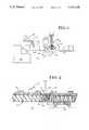
- FIG. 1is a schematic, side elevational rendering of novel apparatus according to the present invention for carrying out the novel method thereof;
- FIG. 2is a magnified side elevational view of a portion of the apparatus schematically shown in FIG. 1;
- FIG. 3is a pressure profile diagram representing the working forces applied to materials by the apparatus of FIG. 2;
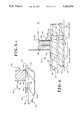
- FIGS. 4 and 4aare partial schematic views of the portion of the apparatus depicted in FIG. 2 as seen from the top.
- Plastic materialsincluding plastic waste such as polystyrene foam resulting from discarding fast food containers, after contact with water, such as occurs during washing to remove food and drink residue, may include up to 50% by weight of water. Recycling of essentially water-free plastic materials, such as polystyrene, could include initial heating in an oven to drive off the water. Following this the polystyrene is melted and worked by one or more extruers into new product or pellets. The pellets would be sold in bulk to manufacturers of polystyrene articles for reuse.
- the present inventionpermits water removal to be achieved in reasonable times with the expenditure of little or no expensive heat energy input.
- apparatus 10 for practicing the present inventioncomprises an extruder or barrel-screw combination 12.
- the extruder 12may take a wide variety of configurations, and may be a single-screw or twin-screw extruder or compounder.
- a screw portion 14 of the barrel-screw 12may be right-handed or left-handed. Where the screw portion 14 is a twin screw, the individual screws thereof may be co-rotating and intermeshing or may take other forms. Further, the screw portion 14 may comprise screw segments, right-handed and/or left-handed, mounted or keyed to a common rotating member (not shown), as is well known.
- One preferred extruder 12is an appropriate model of ZSK (Zweiwellen Schnecken Kreter) co-rotating, intermeshing, twin-screw extruder manufactured and sold by the assignee of the present invention.
- the extruder 12also includes a barrel portion 16 within a bore or bores of which the screw portion 14 rotates, as is well known.
- the barrel portion 16may comprise a plurality of barrel sections, such as 16a-16e, having internal bores with which the screw segments of the screw portion 14 cooperate to transport and work material so as to effect water removal, as described below.
- the screw portion 14may extend beyond barrel section 16e and into additional down-stream barrel sections, constituting a down-stream barrel portion 18, which in cooperation with the screw portion 14 therein processes the now dewatered material into new product or pellets in any well known manner.
- the barrel section 16ahouses a section (not shown) of the screw portion 14 which is connected to a motive power source 20 capable of selectively rotating the screw portion 14.
- the barrel section 16bcontains a feed opening 22 for receiving material 24 to be dewatered. Feeding may be achieved by a belt feeder or the like, as schematically shown at 26.
- the material 24may comprise any substance which is capable of being transported and worked by the barrel-screw 12.
- this materialmay comprise comminuted polystyrene foam or foam crumb in flake or particulate form, and constitutes polystyrene particles of about 1.0 square centimeters having a bulk density of about 7 pounds per cubic foot and including from about 15% to about 45%-50% by weight of water.
- the included watercomes primarily from the water used to wash and rinse the polystyrene to remove food and drink residue. Washing, rinsing and comminuting are not depicted and may be carried out in any convenient manner prior to the feed opening 22 receiving the material 24.
- the water presentmay come from other processing steps.
- watermay be present as a result of vaporizing solvents from rubber solutions by passing steam and water through the solution.
- Watermay also be present as a result of producing slurries of paper, cane or wood pulp or from previous processing of any extruder-workable material which has a high surface area.
- the segment (not shown) of the screw portion 14 within the barrel sections 16b and 16ccontains a thread worm or ribbon having a crest and a base which is effective to transport the material 24 rightwardly in FIG. 1. This transporting continues in the barrel section 16d.
- the cooperation between the sections of the screw portion 14 and the barrel sections 16b-16d of the barrel portion 16is such that so-called starved feeding of the material 24 is utilized at the feed opening 22. Further, during the transport process, the material is and remains substantially unmelted. This may be achieved by the starved feeding of the material 24, as well as by not adding heat (or cooling, if necessary) the barrel sections 16b-16d. Any known technique may be utilized to prevent substantial melting of the material 24, including adjusting the degree of cooperation and the resultant shear between the screw portion 14 and the barrel portion 16 in any known manner.
- the material 24is transported by the barrel-screw 12 to a barrel section 16e which contains an extraction location 50 whereat water contained therein is extracted.
- the transport of the material 24 by the action of the barrel-screw 12is primarily due to drag forces, that is, to the action of the thread of the screw portion 14 on the material 24 and the cooperative effect of the screw portion 14 and the barrel portion 16 on the material 24.
- drag forcesare effective to transport the material 24 due to its high viscosity.
- the transport of low viscosity materials by a non-positive displacement device such as the barrel-screw 12is inefficient at best if it occurs at all.
- the barrel-screw 12is shown to include twin, co-rotating, intermeshing screw segments 14a.
- a single screw portion 14amay, of course, be utilized.
- twin screw segments 14aone of the screw segments 14a within the barrel section 16d is diagramatically shown to include a thread 52 defined by a base 54 and a crest 56. As the screw portion 14 and its included segment 14a rotate, the crest 56 sweeps out an envelope, depicted at 58.
- the handedness of the screw portion 14changes. If the segment 14a of the screw portion 14 within the extraction location 50 is right-handed, a short segment 14b thereof within or downstream of the extraction location 50 is left-handed.
- the pressures P u in the vicinity of and upstream of the extraction location 50are due to forces on the material 24 which tend to move rightwardly and compact the material 24.
- the presssure P d within or downstream of the extraction location 50are due to forces on the material 24 within or downstream of the extraction location 50 which tend to move leftwardly and compact the material 24.
- the screw portion 14may change handedness within or downstream of the extraction location 50.
- other flow restricting techniquesmay be utilized to extract water from the material 24.
- the Segment 14bmay have a smaller, less severe pitch than the Segment 14a or may have no pitch.
- Other restrictive techniqueswhich result in water being squeezed from the material 24 may also be used.
- an opening 60is formed in the wall of the barrel section 16d.
- This opening 60communicates with and is a continuation of the bore of a second barrel-screw which may be a feeder 62.
- the barrel 64 of the second barrel-screw 62is mounted to the barrel section 16d, and the screw or screws 66 of the barrel-screw 62 access the bore of the barrel section 16d.
- the barrel-screws 12 and 62are so related that the terminus 68 of the screw 66 is closely spaced from the envelope 58 swept out by the crest 56 of the thread 52 on the screw segment 14a.
- this spacing 70is about two to three millimeters and may be as small as one millimeter.
- the barrel-screw 62may take any convenient configuration.
- the barrel-screw 62may be a co-rotating, intermeshing twin-screw feeder or machine, manufactured and sold by the assignee of the present invention under the designation ZSB.
- the screw(s) 66 of the barrel-screw 62are configured so as to move material downwardly as viewed in FIGS. 4 and 4a or out of the plane of the drawing as viewed in FIGS. 1-3.
- the barrel-screw 62applies, or attempts to apply, drag force to substances in much the same manner as the extruder 12. Where the material 24 is a viscous substance like polystyrene, the barrel-screws 12 and 62 are able to quite efficiently transport and work or compact it. Where the substance is essentially non-viscous like water, the barrel-screws 12 and 62 are essentially unable to effect transport thereof.
- the water included in the polystyrenereaches the extraction location 50 due to the efficient transport of the material 24 by the barrel-screw 12.
- the wateris squeezed from the material 24 by the rightward forces and their resulting pressures P u and by the opposing first and second forces acting along the extruder 12.
- the extracted waternow no longer incorporated in the material 24, is free to flow via the clearances of the barrel-screw 12, out of the opening 60 and into the barrel-screw 62.
- the watermay thereafter be removed from the barrel-screw 62 via a drain, slots or the like which do not clog because the material 24 is not permitted to enter the barrel 64 by the action of its screws 66.
- the material 24 being worked in the barrel section 16 d as the water flows out of the opening 60is itself prevented from passing through the opening 60 by the action of the barrel-screw 62 and the close spacing of the terminus 68 of the screw(s) 66 from the envelope 58. Any of the material 24 tending to flow through the opening 60 is maintained or forced back into the barrel section 16d by the action of the barrel-screw 62.
- the barrel-screw 62is horizontally oriented, although other orientations are possible.
- liquids such as waterare removed from the material 24 by subjecting the material 24 to the effects of a "pinch point " that is, a location marking the confluence of three or more forces.
- the three forces present at the present pinch pointwhich may be at or slightly downstream of the extraction location 50, are produced by the rightward moving and compacting effects of the screw portion 14a (and of screw portions upstream thereof), the leftward moving and compacting effects of the opposite handed portion 14b and the transverse flow-preventing effects of the barrel-screw 62.
- the dewatered material 24may be further worked and processed in the barrel portion 18 downstream of the extraction location 50 to produce pellets thereof or other stock capable of being processed into products made from the material 24.
- additional water extraction stages similar to that described abovemay be provided for serially extracting water from the material 24 until a desired degree of dryness is achieved.
- the extraction location 50may be distributed along the opening 60 from a location where the pressure P u is sufficiently high to extract water to the juncture of the screw portions 14a and 14b. In this way, most extracted water need only flow the short transverse distance from the barrel 16 to the opening 60, while some water, which is extracted at or near the end of the screw portion 14a, flows upstream a very short distance to the opening 60.
Landscapes
- Engineering & Computer Science (AREA)
- Mechanical Engineering (AREA)
- Extrusion Moulding Of Plastics Or The Like (AREA)
Abstract
Description
Claims (10)
Priority Applications (2)
| Application Number | Priority Date | Filing Date | Title |
|---|---|---|---|
| US07/606,561US5151026A (en) | 1990-10-31 | 1990-10-31 | Apparatus for removing liquids from solids |
| US07/878,930US5232649A (en) | 1990-10-31 | 1992-05-06 | Method of removing liquids from solids |
Applications Claiming Priority (1)
| Application Number | Priority Date | Filing Date | Title |
|---|---|---|---|
| US07/606,561US5151026A (en) | 1990-10-31 | 1990-10-31 | Apparatus for removing liquids from solids |
Related Child Applications (1)
| Application Number | Title | Priority Date | Filing Date |
|---|---|---|---|
| US07/878,930DivisionUS5232649A (en) | 1990-10-31 | 1992-05-06 | Method of removing liquids from solids |
Publications (1)
| Publication Number | Publication Date |
|---|---|
| US5151026Atrue US5151026A (en) | 1992-09-29 |
Family
ID=24428466
Family Applications (1)
| Application Number | Title | Priority Date | Filing Date |
|---|---|---|---|
| US07/606,561Expired - LifetimeUS5151026A (en) | 1990-10-31 | 1990-10-31 | Apparatus for removing liquids from solids |
Country Status (1)
| Country | Link |
|---|---|
| US (1) | US5151026A (en) |
Cited By (31)
| Publication number | Priority date | Publication date | Assignee | Title |
|---|---|---|---|---|
| US5290505A (en)* | 1990-11-26 | 1994-03-01 | Wnc-Nitrochemie Gmbh | Method of recycling adhesive-coated plastic sheet material |
| US5700410A (en)* | 1992-10-16 | 1997-12-23 | Nippon Shinyaku Co., Ltd. | Method of manufacturing wax matrices |
| US5711794A (en)* | 1994-07-21 | 1998-01-27 | Chemical Research Technology | Method for continuous production of varnish |
| US5743948A (en)* | 1994-07-21 | 1998-04-28 | Chemical Research Technology | Method for continuous production of varnish |
| US5851463A (en)* | 1995-03-27 | 1998-12-22 | Basf Aktiengesellschaft | Preparation of thermoplastics |
| US5910276A (en)* | 1995-03-27 | 1999-06-08 | Basf Aktiengesellschaft | Preparation of thermoplastics |
| US5958316A (en)* | 1995-03-27 | 1999-09-28 | Basf Aktiengesellschaft | Preparation of thermoplastics |
| US6165399A (en)* | 1996-09-26 | 2000-12-26 | Basf Aktiengesellschaft | Process for producing thermoplastics |
| US6273599B1 (en) | 1999-09-17 | 2001-08-14 | Flint Ink Corporation | Process for preparing pigment flush |
| US6576131B1 (en) | 1997-12-16 | 2003-06-10 | Flint Ink Corporation | Process and apparatus for changing the wetting agent of pigments |
| US20040222543A1 (en)* | 2001-09-14 | 2004-11-11 | Buhler Ag | Elastomer mixtures for rubber manufacture |
| US20050092203A1 (en)* | 2002-03-20 | 2005-05-05 | Sun Chemical Corp. | Continuous process for preparing pigment flush |
| US20060034962A1 (en)* | 2002-09-20 | 2006-02-16 | Basf Aktiengesellschaft | Device for extruding thermoplasts |
| US20060037517A1 (en)* | 2004-08-17 | 2006-02-23 | Flint Ink Corporation | Processes for preparing organic pigment dispersions and ink |
| US20060196388A1 (en)* | 2002-03-20 | 2006-09-07 | Robertson George H | Continuous process for preparing pigment flush |
| US7300468B2 (en) | 2003-10-31 | 2007-11-27 | Whirlpool Patents Company | Multifunctioning method utilizing a two phase non-aqueous extraction process |
| US7513132B2 (en) | 2003-10-31 | 2009-04-07 | Whirlpool Corporation | Non-aqueous washing machine with modular construction |
| US7513004B2 (en) | 2003-10-31 | 2009-04-07 | Whirlpool Corporation | Method for fluid recovery in a semi-aqueous wash process |
| US7534304B2 (en) | 1997-04-29 | 2009-05-19 | Whirlpool Corporation | Non-aqueous washing machine and methods |
| US7695524B2 (en) | 2003-10-31 | 2010-04-13 | Whirlpool Corporation | Non-aqueous washing machine and methods |
| US7739891B2 (en) | 2003-10-31 | 2010-06-22 | Whirlpool Corporation | Fabric laundering apparatus adapted for using a select rinse fluid |
| US7837741B2 (en) | 2004-04-29 | 2010-11-23 | Whirlpool Corporation | Dry cleaning method |
| US7966684B2 (en) | 2005-05-23 | 2011-06-28 | Whirlpool Corporation | Methods and apparatus to accelerate the drying of aqueous working fluids |
| US8262741B2 (en) | 1997-04-29 | 2012-09-11 | Whirlpool Corporation | Non-aqueous washing apparatus and method |
| EP2937209A1 (en)* | 2014-04-22 | 2015-10-28 | Rio Tinto Alcan International Limited | Modular screw press |
| CN107042595A (en)* | 2017-06-16 | 2017-08-15 | 孟定腾鑫实业有限责任公司 | A kind of rubber removal of impurities homogenizer |
| US9939197B2 (en) | 2013-01-25 | 2018-04-10 | Calaeris Energy + Environment Ltd. | Turbulent vacuum thermal separation methods and systems |
| US10047220B2 (en) | 2013-07-02 | 2018-08-14 | Ineos Styrolution Group Gmbh | Process for the manufacturing of ABS-molding compositions |
| WO2022229335A1 (en) | 2021-04-30 | 2022-11-03 | Ineos Styrolution Group Gmbh | Improved process for producing thermoplastic abs molding compositions |
| WO2022229347A1 (en) | 2021-04-30 | 2022-11-03 | Ineos Styrolution Group Gmbh | Improved processes for producing thermoplastic abs molding compositions |
| WO2023083936A1 (en) | 2021-11-12 | 2023-05-19 | Ineos Styrolution Group Gmbh | Thermoplastic abs molding compositions with improved surface |
Citations (9)
| Publication number | Priority date | Publication date | Assignee | Title |
|---|---|---|---|---|
| US2985909A (en)* | 1958-03-20 | 1961-05-30 | Farrel Birmingham Co Inc | Apparatus for demoisturizing plastic materials |
| US3035306A (en)* | 1959-12-01 | 1962-05-22 | Welding Engineers | Dewatering means for plastic materials |
| US3070836A (en)* | 1959-07-09 | 1963-01-01 | Phillips Petroleum Co | Method and apparatus for automatic control of an extruder |
| US3742093A (en)* | 1970-04-08 | 1973-06-26 | Welding Engineers | Method of separating an insoluble liquid from polymer composition |
| US3993292A (en)* | 1974-12-13 | 1976-11-23 | W Bar E, Incorporated | Apparatus for coagulating polymer latex emulsions |
| US4446094A (en)* | 1982-09-23 | 1984-05-01 | Welding Engineers, Inc. | Apparatus and method for extracting fluid from an extruded material |
| US4659300A (en)* | 1983-06-09 | 1987-04-21 | Reifenhauser Gmbh & Co. Maschinenfabrik | Worm extruder for synthetic resin |
| US4776269A (en)* | 1986-11-17 | 1988-10-11 | Exxon Chemical Patents Inc. | Method of agglomerating and dewatering polymeric materials |
| US4943402A (en)* | 1989-10-31 | 1990-07-24 | E. I. Du Pont De Nemours And Company | Process for removing chloroprene dimers from polychloroprene |
- 1990
- 1990-10-31USUS07/606,561patent/US5151026A/ennot_activeExpired - Lifetime
Patent Citations (9)
| Publication number | Priority date | Publication date | Assignee | Title |
|---|---|---|---|---|
| US2985909A (en)* | 1958-03-20 | 1961-05-30 | Farrel Birmingham Co Inc | Apparatus for demoisturizing plastic materials |
| US3070836A (en)* | 1959-07-09 | 1963-01-01 | Phillips Petroleum Co | Method and apparatus for automatic control of an extruder |
| US3035306A (en)* | 1959-12-01 | 1962-05-22 | Welding Engineers | Dewatering means for plastic materials |
| US3742093A (en)* | 1970-04-08 | 1973-06-26 | Welding Engineers | Method of separating an insoluble liquid from polymer composition |
| US3993292A (en)* | 1974-12-13 | 1976-11-23 | W Bar E, Incorporated | Apparatus for coagulating polymer latex emulsions |
| US4446094A (en)* | 1982-09-23 | 1984-05-01 | Welding Engineers, Inc. | Apparatus and method for extracting fluid from an extruded material |
| US4659300A (en)* | 1983-06-09 | 1987-04-21 | Reifenhauser Gmbh & Co. Maschinenfabrik | Worm extruder for synthetic resin |
| US4776269A (en)* | 1986-11-17 | 1988-10-11 | Exxon Chemical Patents Inc. | Method of agglomerating and dewatering polymeric materials |
| US4943402A (en)* | 1989-10-31 | 1990-07-24 | E. I. Du Pont De Nemours And Company | Process for removing chloroprene dimers from polychloroprene |
Cited By (38)
| Publication number | Priority date | Publication date | Assignee | Title |
|---|---|---|---|---|
| US5290505A (en)* | 1990-11-26 | 1994-03-01 | Wnc-Nitrochemie Gmbh | Method of recycling adhesive-coated plastic sheet material |
| US5700410A (en)* | 1992-10-16 | 1997-12-23 | Nippon Shinyaku Co., Ltd. | Method of manufacturing wax matrices |
| US5711794A (en)* | 1994-07-21 | 1998-01-27 | Chemical Research Technology | Method for continuous production of varnish |
| US5743948A (en)* | 1994-07-21 | 1998-04-28 | Chemical Research Technology | Method for continuous production of varnish |
| US5851463A (en)* | 1995-03-27 | 1998-12-22 | Basf Aktiengesellschaft | Preparation of thermoplastics |
| US5910276A (en)* | 1995-03-27 | 1999-06-08 | Basf Aktiengesellschaft | Preparation of thermoplastics |
| US5958316A (en)* | 1995-03-27 | 1999-09-28 | Basf Aktiengesellschaft | Preparation of thermoplastics |
| US6165399A (en)* | 1996-09-26 | 2000-12-26 | Basf Aktiengesellschaft | Process for producing thermoplastics |
| US8262741B2 (en) | 1997-04-29 | 2012-09-11 | Whirlpool Corporation | Non-aqueous washing apparatus and method |
| US7534304B2 (en) | 1997-04-29 | 2009-05-19 | Whirlpool Corporation | Non-aqueous washing machine and methods |
| US6576131B1 (en) | 1997-12-16 | 2003-06-10 | Flint Ink Corporation | Process and apparatus for changing the wetting agent of pigments |
| US6305838B1 (en) | 1999-09-17 | 2001-10-23 | Flint Ink Corporation | Process and apparatus for preparing pigment flush |
| US6348091B1 (en) | 1999-09-17 | 2002-02-19 | Flint Ink Corporation | Process and apparatus for preparing pigment flush in response to a material property value |
| WO2001019926A3 (en)* | 1999-09-17 | 2001-10-04 | Flint Ink Corp | Process for preparing pigment flush |
| US6273599B1 (en) | 1999-09-17 | 2001-08-14 | Flint Ink Corporation | Process for preparing pigment flush |
| US20040222543A1 (en)* | 2001-09-14 | 2004-11-11 | Buhler Ag | Elastomer mixtures for rubber manufacture |
| US7407611B2 (en)* | 2001-09-14 | 2008-08-05 | Buhler Ag | Elastomer mixtures for rubber manufacture |
| US20050092203A1 (en)* | 2002-03-20 | 2005-05-05 | Sun Chemical Corp. | Continuous process for preparing pigment flush |
| US20060196388A1 (en)* | 2002-03-20 | 2006-09-07 | Robertson George H | Continuous process for preparing pigment flush |
| US7914615B2 (en) | 2002-03-20 | 2011-03-29 | Sun Chemical Corporation | Continuous process for preparing pigment flush |
| US20060034962A1 (en)* | 2002-09-20 | 2006-02-16 | Basf Aktiengesellschaft | Device for extruding thermoplasts |
| US7300468B2 (en) | 2003-10-31 | 2007-11-27 | Whirlpool Patents Company | Multifunctioning method utilizing a two phase non-aqueous extraction process |
| US7695524B2 (en) | 2003-10-31 | 2010-04-13 | Whirlpool Corporation | Non-aqueous washing machine and methods |
| US7739891B2 (en) | 2003-10-31 | 2010-06-22 | Whirlpool Corporation | Fabric laundering apparatus adapted for using a select rinse fluid |
| US7513132B2 (en) | 2003-10-31 | 2009-04-07 | Whirlpool Corporation | Non-aqueous washing machine with modular construction |
| US7513004B2 (en) | 2003-10-31 | 2009-04-07 | Whirlpool Corporation | Method for fluid recovery in a semi-aqueous wash process |
| US7837741B2 (en) | 2004-04-29 | 2010-11-23 | Whirlpool Corporation | Dry cleaning method |
| US7947126B2 (en) | 2004-08-17 | 2011-05-24 | Flint Group Incorporated | Processes for preparing organic pigment dispersions and ink |
| US20060037517A1 (en)* | 2004-08-17 | 2006-02-23 | Flint Ink Corporation | Processes for preparing organic pigment dispersions and ink |
| US7966684B2 (en) | 2005-05-23 | 2011-06-28 | Whirlpool Corporation | Methods and apparatus to accelerate the drying of aqueous working fluids |
| US9939197B2 (en) | 2013-01-25 | 2018-04-10 | Calaeris Energy + Environment Ltd. | Turbulent vacuum thermal separation methods and systems |
| US10047220B2 (en) | 2013-07-02 | 2018-08-14 | Ineos Styrolution Group Gmbh | Process for the manufacturing of ABS-molding compositions |
| EP3134194A4 (en)* | 2014-04-22 | 2018-01-24 | Rio Tinto Alcan International Limited | Modular screw press |
| EP2937209A1 (en)* | 2014-04-22 | 2015-10-28 | Rio Tinto Alcan International Limited | Modular screw press |
| CN107042595A (en)* | 2017-06-16 | 2017-08-15 | 孟定腾鑫实业有限责任公司 | A kind of rubber removal of impurities homogenizer |
| WO2022229335A1 (en) | 2021-04-30 | 2022-11-03 | Ineos Styrolution Group Gmbh | Improved process for producing thermoplastic abs molding compositions |
| WO2022229347A1 (en) | 2021-04-30 | 2022-11-03 | Ineos Styrolution Group Gmbh | Improved processes for producing thermoplastic abs molding compositions |
| WO2023083936A1 (en) | 2021-11-12 | 2023-05-19 | Ineos Styrolution Group Gmbh | Thermoplastic abs molding compositions with improved surface |
Similar Documents
| Publication | Publication Date | Title |
|---|---|---|
| US5151026A (en) | Apparatus for removing liquids from solids | |
| US5232649A (en) | Method of removing liquids from solids | |
| EP2766164B1 (en) | Apparatus for processing plastic material | |
| EP0152724B1 (en) | Screw drier particularly for plastic materials, operated by an electric motor through a reducer | |
| EP2766158B1 (en) | Apparatus for processing plastic material | |
| EP2766160B1 (en) | Apparatus for processing plastic material | |
| DE202012012586U1 (en) | Device for processing plastic material | |
| DE2656484A1 (en) | DEVICE FOR PROCESSING REMAINS OR WASTE FROM FOAMED THERMOPLASTIC PLASTICS AND THE LIKE | |
| EP1276597A1 (en) | Device and method for processing thermoplastic synthetic material | |
| AT512149A1 (en) | DEVICE FOR PREPARING PLASTIC MATERIAL | |
| US2991503A (en) | Breaking, mixing, and extrusion apparatus | |
| EP2942173B1 (en) | Method for the preparation of granulate for injection moulding a moulded part | |
| DE2831321A1 (en) | DEVICE AND METHOD FOR RECOVERING WASTE FROM THERMOPLASTIC PLASTIC | |
| DE69811007T2 (en) | Device for the reuse of polyethylene, in particular polyethylene films | |
| CN109719924B (en) | A kind of foaming waste material low temperature splits bubble extruder and extrusion method | |
| US4457227A (en) | Extraction device | |
| JPS62240515A (en) | Device for regenerating waste plastic | |
| AT507856B1 (en) | DEVICE FOR CRUSHING PLASTIC | |
| WO1999026707A1 (en) | Method for the extraction of a substance from a starting material and extraction apparatus for carrying out the method | |
| DE10011949C2 (en) | Plant for the processing of environmentally harmful waste products | |
| KR100508997B1 (en) | Method and apparatus for treating heavy tar | |
| KR100340142B1 (en) | Waste Shredding Device | |
| JPH06285857A (en) | Reclamation method of plastic product and its apparatus | |
| KR830000583Y1 (en) | Recycling device of waste synthetic resin | |
| JP3288629B2 (en) | Friction device for foamed resin molded products |
Legal Events
| Date | Code | Title | Description |
|---|---|---|---|
| AS | Assignment | Owner name:WERNER & PFLEIDERER CORP., NEW JERSEY Free format text:ASSIGNMENT OF ASSIGNORS INTEREST.;ASSIGNORS:ANDERSEN, PAUL G.;KITE-POWELL, KAI L.;REEL/FRAME:005504/0911 Effective date:19901024 | |
| STCF | Information on status: patent grant | Free format text:PATENTED CASE | |
| FEPP | Fee payment procedure | Free format text:PAT HLDR NO LONGER CLAIMS SMALL ENT STAT AS SMALL BUSINESS (ORIGINAL EVENT CODE: LSM2); ENTITY STATUS OF PATENT OWNER: LARGE ENTITY | |
| FPAY | Fee payment | Year of fee payment:4 | |
| AS | Assignment | Owner name:KRUPP WERNER & PFLEIDERER CORPORATION, NEW JERSEY Free format text:CHANGE OF NAME;ASSIGNOR:WERNER & PFLEIDERER CORPORATION;REEL/FRAME:009123/0596 Effective date:19980101 | |
| FEPP | Fee payment procedure | Free format text:PAYOR NUMBER ASSIGNED (ORIGINAL EVENT CODE: ASPN); ENTITY STATUS OF PATENT OWNER: LARGE ENTITY | |
| FPAY | Fee payment | Year of fee payment:8 | |
| AS | Assignment | Owner name:CIBC WORLD MARKETS PLC, UNITED KINGDOM Free format text:SECURITY AGREEMENT;ASSIGNOR:KRUPP WERNER & PFLEIDERER CORPORATION;REEL/FRAME:011425/0685 Effective date:20001221 | |
| AS | Assignment | Owner name:KRUPP WERNER & PFLEIDERER CORPORATION, NEW JERSEY Free format text:CHANGE OF NAME;ASSIGNOR:WERNER & PFLEIDERER CORPORATION;REEL/FRAME:011627/0137 Effective date:19980101 | |
| AS | Assignment | Owner name:COPERION CORPORATION, NEW JERSEY Free format text:CHANGE OF NAME;ASSIGNOR:KRUPP WERNER & PFLEIDERER CORPORATION;REEL/FRAME:011712/0359 Effective date:20010401 | |
| AS | Assignment | Owner name:CIBC WORLD MARKETS PLC, UNITED KINGDOM Free format text:AMENDMENT TO SECURITY AGREEMENT;ASSIGNOR:COPERION CORPORATION;REEL/FRAME:011958/0030 Effective date:20010627 | |
| AS | Assignment | Owner name:CIBC WORLD MARKETING PLC, UNITED KINGDOM Free format text:DOCUMENT PREIVOUSLY RECORDED AT REEL 011425 FRAME 0685 CONTAINED ERRORS IN PROPERTY NUMBERS 09224360, 09021907 AND 52335349. DOCUMENT RERECORDED TO CORRECT ERRORS ON STATED REEL.;ASSIGNOR:KRUPP WERNER & PFLEIDERER CORPORATION;REEL/FRAME:012134/0021 Effective date:20001221 | |
| REMI | Maintenance fee reminder mailed | ||
| FPAY | Fee payment | Year of fee payment:12 | |
| SULP | Surcharge for late payment | Year of fee payment:11 |