US5150583A - Apparatus for controlling a dual evaporator, dual fan refrigerator with independent temperature controls - Google Patents
Apparatus for controlling a dual evaporator, dual fan refrigerator with independent temperature controlsDownload PDFInfo
- Publication number
- US5150583A US5150583AUS07/834,089US83408992AUS5150583AUS 5150583 AUS5150583 AUS 5150583AUS 83408992 AUS83408992 AUS 83408992AUS 5150583 AUS5150583 AUS 5150583A
- Authority
- US
- United States
- Prior art keywords
- evaporator
- fresh food
- compartment
- fan
- situated
- Prior art date
- Legal status (The legal status is an assumption and is not a legal conclusion. Google has not performed a legal analysis and makes no representation as to the accuracy of the status listed.)
- Expired - Fee Related
Links
- 230000009977dual effectEffects0.000titledescription18
- 239000003507refrigerantSubstances0.000claimsabstractdescription22
- 238000001816coolingMethods0.000abstractdescription27
- 230000001276controlling effectEffects0.000description8
- 239000012071phaseSubstances0.000description8
- 230000007423decreaseEffects0.000description6
- 230000001960triggered effectEffects0.000description4
- 230000003247decreasing effectEffects0.000description3
- 239000007788liquidSubstances0.000description3
- 230000004888barrier functionEffects0.000description2
- 230000008901benefitEffects0.000description2
- 239000007789gasSubstances0.000description2
- 238000000034methodMethods0.000description2
- 238000005057refrigerationMethods0.000description2
- 230000001105regulatory effectEffects0.000description2
- 230000033228biological regulationEffects0.000description1
- 238000004891communicationMethods0.000description1
- 230000006835compressionEffects0.000description1
- 238000007906compressionMethods0.000description1
- 238000011217control strategyMethods0.000description1
- 230000000694effectsEffects0.000description1
- 238000005265energy consumptionMethods0.000description1
- 239000007792gaseous phaseSubstances0.000description1
- 238000005184irreversible processMethods0.000description1
- 239000007791liquid phaseSubstances0.000description1
- 239000010687lubricating oilSubstances0.000description1
- 230000008520organizationEffects0.000description1
- 230000009467reductionEffects0.000description1
- 230000004044responseEffects0.000description1
- 230000000630rising effectEffects0.000description1
- 229920006395saturated elastomerPolymers0.000description1
- 238000010792warmingMethods0.000description1
Images


Classifications
- F—MECHANICAL ENGINEERING; LIGHTING; HEATING; WEAPONS; BLASTING
- F25—REFRIGERATION OR COOLING; COMBINED HEATING AND REFRIGERATION SYSTEMS; HEAT PUMP SYSTEMS; MANUFACTURE OR STORAGE OF ICE; LIQUEFACTION SOLIDIFICATION OF GASES
- F25B—REFRIGERATION MACHINES, PLANTS OR SYSTEMS; COMBINED HEATING AND REFRIGERATION SYSTEMS; HEAT PUMP SYSTEMS
- F25B5/00—Compression machines, plants or systems, with several evaporator circuits, e.g. for varying refrigerating capacity
- F25B5/04—Compression machines, plants or systems, with several evaporator circuits, e.g. for varying refrigerating capacity arranged in series
- F—MECHANICAL ENGINEERING; LIGHTING; HEATING; WEAPONS; BLASTING
- F25—REFRIGERATION OR COOLING; COMBINED HEATING AND REFRIGERATION SYSTEMS; HEAT PUMP SYSTEMS; MANUFACTURE OR STORAGE OF ICE; LIQUEFACTION SOLIDIFICATION OF GASES
- F25B—REFRIGERATION MACHINES, PLANTS OR SYSTEMS; COMBINED HEATING AND REFRIGERATION SYSTEMS; HEAT PUMP SYSTEMS
- F25B1/00—Compression machines, plants or systems with non-reversible cycle
- F25B1/10—Compression machines, plants or systems with non-reversible cycle with multi-stage compression
- F—MECHANICAL ENGINEERING; LIGHTING; HEATING; WEAPONS; BLASTING
- F25—REFRIGERATION OR COOLING; COMBINED HEATING AND REFRIGERATION SYSTEMS; HEAT PUMP SYSTEMS; MANUFACTURE OR STORAGE OF ICE; LIQUEFACTION SOLIDIFICATION OF GASES
- F25D—REFRIGERATORS; COLD ROOMS; ICE-BOXES; COOLING OR FREEZING APPARATUS NOT OTHERWISE PROVIDED FOR
- F25D17/00—Arrangements for circulating cooling fluids; Arrangements for circulating gas, e.g. air, within refrigerated spaces
- F25D17/04—Arrangements for circulating cooling fluids; Arrangements for circulating gas, e.g. air, within refrigerated spaces for circulating air, e.g. by convection
- F25D17/06—Arrangements for circulating cooling fluids; Arrangements for circulating gas, e.g. air, within refrigerated spaces for circulating air, e.g. by convection by forced circulation
- F25D17/062—Arrangements for circulating cooling fluids; Arrangements for circulating gas, e.g. air, within refrigerated spaces for circulating air, e.g. by convection by forced circulation in household refrigerators
- F25D17/065—Arrangements for circulating cooling fluids; Arrangements for circulating gas, e.g. air, within refrigerated spaces for circulating air, e.g. by convection by forced circulation in household refrigerators with compartments at different temperatures
- F—MECHANICAL ENGINEERING; LIGHTING; HEATING; WEAPONS; BLASTING
- F25—REFRIGERATION OR COOLING; COMBINED HEATING AND REFRIGERATION SYSTEMS; HEAT PUMP SYSTEMS; MANUFACTURE OR STORAGE OF ICE; LIQUEFACTION SOLIDIFICATION OF GASES
- F25D—REFRIGERATORS; COLD ROOMS; ICE-BOXES; COOLING OR FREEZING APPARATUS NOT OTHERWISE PROVIDED FOR
- F25D29/00—Arrangement or mounting of control or safety devices
- F—MECHANICAL ENGINEERING; LIGHTING; HEATING; WEAPONS; BLASTING
- F25—REFRIGERATION OR COOLING; COMBINED HEATING AND REFRIGERATION SYSTEMS; HEAT PUMP SYSTEMS; MANUFACTURE OR STORAGE OF ICE; LIQUEFACTION SOLIDIFICATION OF GASES
- F25B—REFRIGERATION MACHINES, PLANTS OR SYSTEMS; COMBINED HEATING AND REFRIGERATION SYSTEMS; HEAT PUMP SYSTEMS
- F25B2400/00—General features or devices for refrigeration machines, plants or systems, combined heating and refrigeration systems or heat-pump systems, i.e. not limited to a particular subgroup of F25B
- F25B2400/13—Economisers
- F—MECHANICAL ENGINEERING; LIGHTING; HEATING; WEAPONS; BLASTING
- F25—REFRIGERATION OR COOLING; COMBINED HEATING AND REFRIGERATION SYSTEMS; HEAT PUMP SYSTEMS; MANUFACTURE OR STORAGE OF ICE; LIQUEFACTION SOLIDIFICATION OF GASES
- F25B—REFRIGERATION MACHINES, PLANTS OR SYSTEMS; COMBINED HEATING AND REFRIGERATION SYSTEMS; HEAT PUMP SYSTEMS
- F25B2400/00—General features or devices for refrigeration machines, plants or systems, combined heating and refrigeration systems or heat-pump systems, i.e. not limited to a particular subgroup of F25B
- F25B2400/23—Separators
- F—MECHANICAL ENGINEERING; LIGHTING; HEATING; WEAPONS; BLASTING
- F25—REFRIGERATION OR COOLING; COMBINED HEATING AND REFRIGERATION SYSTEMS; HEAT PUMP SYSTEMS; MANUFACTURE OR STORAGE OF ICE; LIQUEFACTION SOLIDIFICATION OF GASES
- F25B—REFRIGERATION MACHINES, PLANTS OR SYSTEMS; COMBINED HEATING AND REFRIGERATION SYSTEMS; HEAT PUMP SYSTEMS
- F25B2600/00—Control issues
- F25B2600/02—Compressor control
- F25B2600/025—Compressor control by controlling speed
- F25B2600/0251—Compressor control by controlling speed with on-off operation
- F—MECHANICAL ENGINEERING; LIGHTING; HEATING; WEAPONS; BLASTING
- F25—REFRIGERATION OR COOLING; COMBINED HEATING AND REFRIGERATION SYSTEMS; HEAT PUMP SYSTEMS; MANUFACTURE OR STORAGE OF ICE; LIQUEFACTION SOLIDIFICATION OF GASES
- F25D—REFRIGERATORS; COLD ROOMS; ICE-BOXES; COOLING OR FREEZING APPARATUS NOT OTHERWISE PROVIDED FOR
- F25D11/00—Self-contained movable devices, e.g. domestic refrigerators
- F25D11/02—Self-contained movable devices, e.g. domestic refrigerators with cooling compartments at different temperatures
- F25D11/022—Self-contained movable devices, e.g. domestic refrigerators with cooling compartments at different temperatures with two or more evaporators
- F—MECHANICAL ENGINEERING; LIGHTING; HEATING; WEAPONS; BLASTING
- F25—REFRIGERATION OR COOLING; COMBINED HEATING AND REFRIGERATION SYSTEMS; HEAT PUMP SYSTEMS; MANUFACTURE OR STORAGE OF ICE; LIQUEFACTION SOLIDIFICATION OF GASES
- F25D—REFRIGERATORS; COLD ROOMS; ICE-BOXES; COOLING OR FREEZING APPARATUS NOT OTHERWISE PROVIDED FOR
- F25D2317/00—Details or arrangements for circulating cooling fluids; Details or arrangements for circulating gas, e.g. air, within refrigerated spaces, not provided for in other groups of this subclass
- F25D2317/06—Details or arrangements for circulating cooling fluids; Details or arrangements for circulating gas, e.g. air, within refrigerated spaces, not provided for in other groups of this subclass with forced air circulation
- F25D2317/068—Details or arrangements for circulating cooling fluids; Details or arrangements for circulating gas, e.g. air, within refrigerated spaces, not provided for in other groups of this subclass with forced air circulation characterised by the fans
- F25D2317/0682—Two or more fans
- F—MECHANICAL ENGINEERING; LIGHTING; HEATING; WEAPONS; BLASTING
- F25—REFRIGERATION OR COOLING; COMBINED HEATING AND REFRIGERATION SYSTEMS; HEAT PUMP SYSTEMS; MANUFACTURE OR STORAGE OF ICE; LIQUEFACTION SOLIDIFICATION OF GASES
- F25D—REFRIGERATORS; COLD ROOMS; ICE-BOXES; COOLING OR FREEZING APPARATUS NOT OTHERWISE PROVIDED FOR
- F25D2400/00—General features of, or devices for refrigerators, cold rooms, ice-boxes, or for cooling or freezing apparatus not covered by any other subclass
- F25D2400/04—Refrigerators with a horizontal mullion
- F—MECHANICAL ENGINEERING; LIGHTING; HEATING; WEAPONS; BLASTING
- F25—REFRIGERATION OR COOLING; COMBINED HEATING AND REFRIGERATION SYSTEMS; HEAT PUMP SYSTEMS; MANUFACTURE OR STORAGE OF ICE; LIQUEFACTION SOLIDIFICATION OF GASES
- F25D—REFRIGERATORS; COLD ROOMS; ICE-BOXES; COOLING OR FREEZING APPARATUS NOT OTHERWISE PROVIDED FOR
- F25D2700/00—Means for sensing or measuring; Sensors therefor
- F25D2700/12—Sensors measuring the inside temperature
- F25D2700/122—Sensors measuring the inside temperature of freezer compartments
- Y—GENERAL TAGGING OF NEW TECHNOLOGICAL DEVELOPMENTS; GENERAL TAGGING OF CROSS-SECTIONAL TECHNOLOGIES SPANNING OVER SEVERAL SECTIONS OF THE IPC; TECHNICAL SUBJECTS COVERED BY FORMER USPC CROSS-REFERENCE ART COLLECTIONS [XRACs] AND DIGESTS
- Y02—TECHNOLOGIES OR APPLICATIONS FOR MITIGATION OR ADAPTATION AGAINST CLIMATE CHANGE
- Y02B—CLIMATE CHANGE MITIGATION TECHNOLOGIES RELATED TO BUILDINGS, e.g. HOUSING, HOUSE APPLIANCES OR RELATED END-USER APPLICATIONS
- Y02B40/00—Technologies aiming at improving the efficiency of home appliances, e.g. induction cooking or efficient technologies for refrigerators, freezers or dish washers
Definitions
- the present inventionrelates to controls for independently adjusting the temperatures in the freezer and fresh food compartments in a refrigerator having an evaporator in the freezer compartment and an evaporator in the fresh food compartment.
- the presently used refrigeration cycle in household refrigeratorsis the simple vapor compression type using a single evaporator.
- Relative cooling rates for the freezer and the fresh food compartmentsare controlled by the user.
- a user adjusted controlsets the fixed fraction of the total cold air flow provided by the single evaporator and fan which is to reach the two refrigerator compartments.
- the compressoroperates allowing the evaporator to supply cold air. Since the fraction of cold air provided to the fresh food and freezer compartments does not vary once set, control of freezer temperature is imperfect and freezer air temperatures vary considerably. Changes in the ambient temperature, time defrosts of the freezer compartment, and changes of incidental thermal loads (door opening frequency and duration) requires time varying changes in the fraction of cold air delivered to both compartments to properly control the temperature in both compartments.
- a refrigerator apparatushaving a cabinet with a freezer compartment and a fresh food compartment.
- the compartmentsdefine two passageways allowing air circulation therebetween.
- a refrigerator systemis included having a compressor, a condenser, an expansion valve, an evaporator situated in the freezer compartment.
- the refrigerator system elementsare connected in series in a closed loop, in a refrigerant flow relationship.
- a first fanis situated in the freezer compartment for providing air flow over the evaporator.
- a second fanis situated in one of the two passageways for providing air circulation between the two compartments.
- a first thermostatic controllersituated in the freezer compartment for maintaining a desired temperature in the freezer compartment by causing the compressor and the first fan to operate.
- a second thermostatic controllersituated in the fresh food compartment for maintaining a desired temperature in the fresh food compartment by causing operation of the second fan circulating air between the compartments thereby cooling the fresh food compartment.
- a refrigerator apparatushaving a freezer compartment, a fresh food compartment, and a refrigerator system.
- the refrigerator systemincludes a first expansion valve, a first evaporator situated in the freezer compartment, a first and second compressor, a condenser, a second expansion valve, and a second evaporator situated in the fresh food compartment. All of the elements of the refrigerator system are connected in series, in the order listed in a refrigerant flow relationship.
- a phase separatorconnects the second evaporator to the first expansion valve in a refrigerant flow relationship. The phase separator provides intercooling between the first and second compressors.
- a first fanis situated in the freezer compartment for providing air flow over the first evaporator.
- a second fanis situated in the fresh food compartment for providing air flow over the second evaporator.
- a servovalve connected to the input of the first compressorreduces the refrigerant mass flow rate through the first evaporator when the servovalve is activated.
- a first thermostatic controlleris situated in the freezer compartment for maintaining a desired temperature in the freezer compartment by causing operation of the compressor and the fans.
- a second thermostatic controlleris situated in the fresh food compartment for maintaining a desired temperature in the fresh food compartment by causing operation of the servovalve reducing the mass flow rate in the first evaporator.
- a refrigerator apparatusincluding a freezer compartment, a fresh food compartment and a refrigerator system.
- the refrigerator systemhas a compressor, a condenser, a first expansion valve, a first evaporator situated in the freezer compartment, a second expansion valve, a second evaporator situated in the fresh food compartment.
- the refrigerator system elementsare connected in series in a closed loop in a refrigerant flow relationship.
- a first fanis situated in the freezer compartment for providing air flow over the first evaporator.
- a second fanis situated in the fresh food compartment for providing air flow over the second evaporator.
- a first thermostatic controlleris situated in the freezer compartment for maintaining a desired temperature in the freezer compartment by causing operation of the compressor and the first fan.
- a second thermostatic controlleris situated in the fresh food compartment for maintaining a desired temperature in the fresh food compartment by causing the second second fan to operate as necessary when the compressor is operating.
- FIG. 1is a schematic representation of one embodiment of the dual evaporator refrigerator system with a control for controlling the relative cooling rates of the evaporators, in accordance with the present invention
- FIG. 2is a schematic representation of one embodiment of a dual evaporator two stage refrigerator system with a control for controlling the relative cooling rates of the evaporators in accordance with the present invention
- FIG. 3is a schematic representation of another embodiment of the dual evaporator refrigerator system with a control for controlling the relative cooling rates of the two evaporators in accordance with the present invention
- FIG. 4is a schematic representation of another embodiment of the dual evaporator refrigerator system with a control system in accordance with the present invention
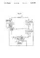
- FIG. 5is a schematic representation of another embodiment of a dual evaporator two stage refrigerator system with a control for controlling the relative cooling rates of the evaporators in accordance with the present invention.
- FIG. 6is a schematic representation of the interior of the fresh food and freezer compartments of a refrigerator in accordance with the present invention showing a control for controlling the relative cooling of the freezer and fresh food compartments where dual evaporators are used.
- the dual evaporator two stage systemcomprises a first expansion valve 11, a first evaporator 13, a first and second hermetically sealed compressor and motor 15 and 17, respectively, a condenser 21, a second expansion valve 23, and a second evaporator 25, connected together in that order, in series, in a refrigerant flow relationship by conduit 26.
- a phase separator 27provides intercooling between the two compressors and comprises a closed receptacle having at the upper portion an inlet for admitting liquid and gaseous phase refrigerant and having two outlets.
- the first outletis located at the bottom the receptacle and provides liquid refrigerant.
- the second outletis provided by a conduit 29 which extends from the interior of the upper portion of the receptacle to the exterior.
- the conduitis in flow communication with the upper portion and is arranged so that liquid refrigerant entering the upper portion of the receptacle cannot enter the open end of the conduit 29.
- Two phase refrigerant from the outlet of the second evaporator 25is connected to the inlet of the phase separator 27.
- the phase separatorprovides liquid refrigerant to the first expansion valve 11.
- the phase separatoralso provides saturated refrigerant vapor which combines with vapor output by the first hermetically sealed compressor and motor 15 and together are connected to the inlet of the second hermetically sealed compressor and motor 17.
- the first evaporator 13contains refrigerant at a temperature of approximately -10° F. during operation for cooling a freezer compartment 31.
- the evaporator 13is situated in an evaporator chamber defined by walls 33 of the freezer and a barrier 35.
- a fan 37situated between the evaporator chamber and the rest of the freezer compartment, when operating, draws air from the freezer into the evaporator chamber over the evaporator 13 and back into the freezer compartment 31.
- the second evaporator 25contains refrigerant at a temperature of approximately 25° F. during operation for cooling the fresh food compartment 41.
- the evaporator 25is situated in an evaporator chamber in the fresh food compartment 25 defined by walls 43 of the refrigerator compartment and a barrier 45.
- a fan 47situated between the evaporator chamber and the rest of the fresh food compartment 41, when operating, draws air from the rest of the compartment across the evaporator and back to the compartment.
- a thermostatic control 51is situated in the freezer compartment 31 and another thermostatic control 53 in the fresh food compartment 41. Both thermostatic controls are adjustable by the user.
- a servovalve 55which is electrically actuated is situated in the conduit 26 between the evaporator 13 of the freezer compartment 31 and the hermetically sealed compressor and motor. The servovalve 55 upon actuation restricts the flow of refrigerant to approximately half the inlet pressure.
- Thermostatic control 51 in the freezer compartmentis coupled to both hermetically sealed motors 57 and 59 through motor controllers 61 and 63 and to the fans 37 and 47 in both compartments 31 and 41.
- both compressors 65 and 67are operated by sending a signal from the thermostatic controllers to the motor controllers 61 and 63 as well as both fans 37 and 47 which also have motor controllers. All the motor controllers are connected to external power supplies (not shown).
- the thermostatic control 53 in the fresh food compartment 41rises above a preselected set point, the servovalve 55 is actuated reducing the inlet pressure in the suction line leading to compressor 65.
- throttling the nominal 19 psia inlet pressure to 9.5 psiacauses the mass flow through the evaporator 13 in the freezer compartment to decrease by more than 50%, thereby decreasing evaporator 13 cooling rate by more than 50%.
- the result of decreasing the cooling rate of the evaporator 13is that it takes a longer time for the freezer compartment to be cooled to the temperature at which the thermostatic control 51 shuts off the compressors.
- the compressorsoperate for a longer time and the fresh food compartment receives more cooling than when the servovalve 55 is not actuated.
- This throttlingis an irreversible process and is accompanied by a decrease of cooling efficiency.
- the mechanical energy to compress the gasremains the same, while the cooling rate decreases by more than 50%.
- the throttled compressor 65only uses approximately 12% of the system's mechanical energy while providing approximately 50% of its cooling. Therefore, a decrease in the efficiency of the compressor 65 and evaporator 13 does not have a substantial effect on overall system efficiency.
- a servovalve 71is positioned to provide a bypass across hermetically sealed compressor and motor 15.
- Servovalve 71provides an open and closed position. The open position recirculates some already compressed gas to the compressor 65 inlet.
- the thermostatic control in the freezer 51still operates both compressors 15 and 17 and fans 37 and 47 when it detects a temperature above its predetermined set point.
- the servovalve 71when actuated by the thermostatic control 53 in the fresh food compartment 41 rising above its preset point causes the servovalve 71 to open reducing the mass flow rate through the evaporator 13 by approximately 50%.
- An advantage to the control scheme of FIG. 2 as compared to FIG. 1is that since full flow occurs through the compressor 65 inlet section, the amount of lubricating oil entrained within the refrigerant vapor is not effected. The reduction in efficiency of the system of FIG. 1 and FIG. 2 when the servovalves are operating are approximately the same.
- the compressors 65 and 67are operated based on freezer temperature and the cooling rate in the freezer compartment can be decreased when the temperature is above a predetermined amount in the fresh food compartment.
- the thermostatic control 53 of the fresh food compartmentis connected to one input of a logical AND gate 73 and the other input is provided from the other thermostatic control 51.
- the output of the AND gate 73is connected to the fan 47.
- the thermostatic control 51 in the freezer compartmentwhen above a preset temperature activates both compressors 65 and 67 and the fan 37 in the freezer compartment 31.
- the thermostatic control 53 in the fresh food compartmentactivates the fresh food fan when the temperature rises above its set point and the compressors are operating.
- the fan 47 in the fresh food compartment 41is shut off because AND gate 73 is not enabled and cooling of the fresh food compartment 41 is stopped.
- the cooling rate produced by the evaporator 13 in the freezer compartment 31is only minimally affected. System efficiency will decrease somewhat while the fresh food compartment fan 47 does not operate.
- the thermostatic control of the fresh food compartment 41is connected to both motor controllers 61 and 63 and to fan 47 and causes both compressors 65 and 67 to operate as well as the fresh food fan 47 when the temperature of the fresh food compartment goes above a preset point.
- the thermostatic control 51 in the freezer compartment 31is connected to one input of a logical AND gate 75 and the output of the fresh food thermostatic control 53 is connected to the other.
- the output of the AND gateis connected to fan 37.
- the thermostatic controller 53 in the fresh food compartment 41is connected to the compressor motor controller 63 and fan 47 and controls the operation of the compressor 67 and the fan 47.
- the thermostatic controller 53also provides one input to AND gate 77, with the output of the AND gate connected to motor controller 61 of compressor 65.
- the output of the AND gate 77also controls the freezer fan 37.
- the thermostatic controller 51 of the freezer 31 when it rises above a preset temperatureprovides a logical "1" or high state to an inverting input of an AND gate 81.
- the output of AND gate 81is connected to a timer 83 which when receiving a transitioning from the low to high state outputs a high signal for a predetermined length of time.
- the output of timer 83is also connected to the input of timer 85 which also provides a high output for a predetermined duration when triggered by receiving a signal transitioning from a low to a high state.
- the output of timer 85is connected to an inverting input of AND gate 77.
- An inverting inputchanges the logical state of the input signal before it is supplied to the AND gate.
- An inverting inputacts as if a separate inverter receives the signal and then provides it to the AND gate.
- the fresh food thermostat 53controls compressor 67 and fan 47.
- a logical one signalis provided by the thermostat to the inverting input of AND gate 81.
- the output of timer 83 when not operating,is at a low state which is connected to the inverting input of AND gate 77.
- the fresh food thermostatis also above its set point compressor 65 and fan 37 operate.
- a logical "0" signalis provided to one inverting input of AND gate 81.
- timer 85when not operating has its output at a low state connected to the other inverting terminal of AND gate 81 enabling AND gate 81 and starting timer 83 which provides a high signal to one inverting input of AND gate 77 disabling AND gate 77 and compressor 65 and fan 37 do not operate.
- Timer 85is triggered by timer 83 and disables AND gate 81 until timer 85 times out thereby controlling the time between subsequent shut downs of compressor 65 when compressor 67 is operating.
- timer 83determines how long single compressor operation occurs and timer 85 determines how long after timer 83 was first triggered it can be triggered again to allow single compressor operation to again occur.
- FIG. 6a refrigerator having separate evaporator 25 in the fresh food compartment 31 and a separate evaporator 13 in the freezer compartment 31 is shown.
- the thermostatic controller 51 in the freezer compartmentis connected to the motor controllers of the hermetically sealed compressors (not shown) and to fans 37 and 47 in the freezer and fresh food compartments, respectively.
- the thermostatic controller 53is connected to a fan 87 located in one of the two passageways interconnecting the fresh food and freezer compartments.
- Fan 87can comprise a low energy consumption fan such as a piezoelectric fan.
- thermostatic controller 51In operation, when thermostatic controller 51 detects the temperature in the freezer has risen above the user selected set point, the compressors (not shown) operate, providing cooled refrigerant in the two evaporators 13 and 25. Fans 37 and 47 circulate air over the evaporators 13 and 25.
- Fan 87When the fresh food compartment thermostatic controller detects that the temperature in the fresh food compartment is above the desired user selected temperature fan 87 operates circulating air between the compartments cooling the fresh food compartment while warming the freezer compartment. Fan 87 operates whenever the fresh food compartment is above a preselected temperature, whether or not the compressors are operating.
- the compressors showndo not have to be intercooled in order for the controls provided to regulate freezer and fresh food compartment temperature.
- Other intercooling techniquessuch as shown in copending application Ser. No. 07/288,848 can alternatively be used.
- the control shown in FIGS. 3 and 4do not require a two stage compressor only two evaporators one operating at temperature to cool the freezer compartment and one operating to cool the fresh food compartment.
- the control of FIG. 6does not require two compressors or two evaporators. A single evaporator located in the freezer compartment with the freezer thermostat controlling the single compressor operation is sufficient. The thermostatic control in the fresh food compartment would still be used to operate the fan controlling airflow between the compartments.
- FIGS. 1, 2 and 3can be combined with the control strategy of FIG. 6 which provides for air circulation between the fresh food and freezer compartments when the fresh food compartment temperature is above a predetermined set point.
- the combination of the air circulation controls with the controls of FIGS. 1, 2, and 3would provide improved fresh food compartment temperature regulation.
Landscapes
- Engineering & Computer Science (AREA)
- Physics & Mathematics (AREA)
- Mechanical Engineering (AREA)
- Thermal Sciences (AREA)
- General Engineering & Computer Science (AREA)
- Chemical & Material Sciences (AREA)
- Combustion & Propulsion (AREA)
- Devices That Are Associated With Refrigeration Equipment (AREA)
Abstract
Description
Claims (1)
Priority Applications (2)
| Application Number | Priority Date | Filing Date | Title |
|---|---|---|---|
| US07/834,089US5150583A (en) | 1989-01-03 | 1992-02-12 | Apparatus for controlling a dual evaporator, dual fan refrigerator with independent temperature controls |
| US07/898,594US5220806A (en) | 1989-01-03 | 1992-06-15 | Apparatus for controlling a dual evaporator, dual fan refrigerator with independent temperature controls |
Applications Claiming Priority (2)
| Application Number | Priority Date | Filing Date | Title |
|---|---|---|---|
| US07/293,034US4966010A (en) | 1989-01-03 | 1989-01-03 | Apparatus for controlling a dual evaporator, dual fan refrigerator with independent temperature controls |
| US07/834,089US5150583A (en) | 1989-01-03 | 1992-02-12 | Apparatus for controlling a dual evaporator, dual fan refrigerator with independent temperature controls |
Related Parent Applications (1)
| Application Number | Title | Priority Date | Filing Date |
|---|---|---|---|
| US07/739,364DivisionUS5109678A (en) | 1989-01-03 | 1991-08-02 | Apparatus for controlling a dual evaporator, dual fan refrigerator with independent temperature controls |
Related Child Applications (1)
| Application Number | Title | Priority Date | Filing Date |
|---|---|---|---|
| US07/898,594DivisionUS5220806A (en) | 1989-01-03 | 1992-06-15 | Apparatus for controlling a dual evaporator, dual fan refrigerator with independent temperature controls |
Publications (1)
| Publication Number | Publication Date |
|---|---|
| US5150583Atrue US5150583A (en) | 1992-09-29 |
Family
ID=26967711
Family Applications (1)
| Application Number | Title | Priority Date | Filing Date |
|---|---|---|---|
| US07/834,089Expired - Fee RelatedUS5150583A (en) | 1989-01-03 | 1992-02-12 | Apparatus for controlling a dual evaporator, dual fan refrigerator with independent temperature controls |
Country Status (1)
| Country | Link |
|---|---|
| US (1) | US5150583A (en) |
Cited By (15)
| Publication number | Priority date | Publication date | Assignee | Title |
|---|---|---|---|---|
| US5406805A (en)* | 1993-11-12 | 1995-04-18 | University Of Maryland | Tandem refrigeration system |
| RU2137064C1 (en)* | 1994-11-11 | 1999-09-10 | Самсунг Электроникс Ко., Лтд. | Refrigerator with highly-effective refrigeration cycle with several evaporators (continuous evaporating cycle) and method of control of this refrigerator |
| US6266968B1 (en)* | 2000-07-14 | 2001-07-31 | Robert Walter Redlich | Multiple evaporator refrigerator with expansion valve |
| US6370908B1 (en) | 1996-11-05 | 2002-04-16 | Tes Technology, Inc. | Dual evaporator refrigeration unit and thermal energy storage unit therefore |
| US6405548B1 (en) | 2000-08-11 | 2002-06-18 | General Electric Company | Method and apparatus for adjusting temperature using air flow |
| US6598410B2 (en)* | 2001-03-21 | 2003-07-29 | Kabushiki Kaisha Toshiba | Refrigerator with a plurality of parallel refrigerant passages |
| US6715305B2 (en)* | 2002-01-15 | 2004-04-06 | Kabushiki Kaisha Toshiba | Two-evaporator refrigerator having a controlled variable throttler |
| FR2864212A1 (en)* | 2003-12-19 | 2005-06-24 | Armines Ass Pour La Rech Et Le | THERMODYNAMIC SYSTEM FOR EVAPORATION, TIERED AND COOLED, COOLED FOR MIXTURES WITH HIGH TEMPERATURE SLIP |
| US20050198996A1 (en)* | 2004-03-15 | 2005-09-15 | Sanyo Electric Co., Ltd. | Refrigerating machine |
| CN100387914C (en)* | 2005-03-30 | 2008-05-14 | 三洋电机株式会社 | Freezers and Refrigerators |
| US20080141681A1 (en)* | 2004-02-10 | 2008-06-19 | Its Kool, Llc | Personal Heat Control Device and Method |
| US20150059370A1 (en)* | 2013-09-05 | 2015-03-05 | Lg Electronics Inc. | Refrigerator and method of controlling a refrigerator |
| EP2772706A3 (en)* | 2013-02-28 | 2015-04-01 | Whirlpool Corporation | Refrigeration system having dual suction port compressor |
| US20160320116A1 (en)* | 2013-12-18 | 2016-11-03 | BSH Hausgeräte GmbH | Refrigeration device having a plurality of refrigeration compartments |
| US20170191727A1 (en)* | 2016-01-05 | 2017-07-06 | Lg Electronics Inc. | Refrigerator and method of controlling the same |
Citations (6)
| Publication number | Priority date | Publication date | Assignee | Title |
|---|---|---|---|---|
| US3005321A (en)* | 1959-08-25 | 1961-10-24 | Philco Corp | Multiple temperature refrigerator |
| US3107502A (en)* | 1961-04-24 | 1963-10-22 | Whirlpool Co | Air circuit means for combined freezer and refrigerator apparatus |
| US3119240A (en)* | 1962-06-19 | 1964-01-28 | Philco Corp | Refrigeration apparatus with defrost means |
| US3359751A (en)* | 1966-10-14 | 1967-12-26 | Admiral Corp | Two temperature refrigerator |
| US3455119A (en)* | 1968-02-16 | 1969-07-15 | Gen Motors Corp | Plural compartment high humidity domestic refrigerator |
| US4416119A (en)* | 1982-01-08 | 1983-11-22 | Whirlpool Corporation | Variable capacity binary refrigerant refrigeration apparatus |
- 1992
- 1992-02-12USUS07/834,089patent/US5150583A/ennot_activeExpired - Fee Related
Patent Citations (6)
| Publication number | Priority date | Publication date | Assignee | Title |
|---|---|---|---|---|
| US3005321A (en)* | 1959-08-25 | 1961-10-24 | Philco Corp | Multiple temperature refrigerator |
| US3107502A (en)* | 1961-04-24 | 1963-10-22 | Whirlpool Co | Air circuit means for combined freezer and refrigerator apparatus |
| US3119240A (en)* | 1962-06-19 | 1964-01-28 | Philco Corp | Refrigeration apparatus with defrost means |
| US3359751A (en)* | 1966-10-14 | 1967-12-26 | Admiral Corp | Two temperature refrigerator |
| US3455119A (en)* | 1968-02-16 | 1969-07-15 | Gen Motors Corp | Plural compartment high humidity domestic refrigerator |
| US4416119A (en)* | 1982-01-08 | 1983-11-22 | Whirlpool Corporation | Variable capacity binary refrigerant refrigeration apparatus |
Cited By (38)
| Publication number | Priority date | Publication date | Assignee | Title |
|---|---|---|---|---|
| US5406805A (en)* | 1993-11-12 | 1995-04-18 | University Of Maryland | Tandem refrigeration system |
| EP0984234A3 (en)* | 1994-11-11 | 2000-05-24 | Samsung Electronics Co., Ltd. | Refrigerator having high efficiency multi-evaporator cycle (h.m.cycle) and control method thereof |
| EP0984236A3 (en)* | 1994-11-11 | 2000-05-24 | Samsung Electronics Co., Ltd. | Refrigerator having high efficiency multi-evaporator cycle (h.m.cycle) and control method thereof |
| EP0984230A3 (en)* | 1994-11-11 | 2000-05-17 | Samsung Electronics Co., Ltd. | Refrigerator having high efficiency multi-evaporator cycle (h.m.cycle) and control method thereof |
| EP1596143A3 (en)* | 1994-11-11 | 2005-11-30 | Samsung Electronics Co, Ltd | Control method of a refrigerator |
| EP0984232A3 (en)* | 1994-11-11 | 2000-05-17 | Samsung Electronics Co., Ltd. | Refrigerator having high efficiency multi-evaporator cycle (h.m.cycle) and control method thereof |
| EP0984231A3 (en)* | 1994-11-11 | 2000-05-17 | Samsung Electronics Co., Ltd. | Refrigerator having high efficiency multi-evaporator cycle (h.m.cycle) and control method thereof |
| EP0984229A3 (en)* | 1994-11-11 | 2000-05-17 | Samsung Electronics Co., Ltd. | Refrigerator having high efficiency multi-evaporator cycle (h.m.cycle) and control method thereof |
| EP0984235A3 (en)* | 1994-11-11 | 2000-05-24 | Samsung Electronics Co., Ltd. | Refrigerator having high efficiency multi-evaporator cycle (h.m.cycle) and control method thereof |
| EP0984236A2 (en) | 1994-11-11 | 2000-03-08 | Samsung Electronics Co., Ltd. | Refrigerator having high efficiency multi-evaporator cycle (h.m.cycle) and control method thereof |
| EP0984233A3 (en)* | 1994-11-11 | 2000-05-24 | Samsung Electronics Co., Ltd. | Refrigerator having high efficiency multi-evaporator cycle (h.m.cycle) and control method thereof |
| EP0982552A3 (en)* | 1994-11-11 | 2000-05-17 | Samsung Electronics Co., Ltd. | Refrigerator having high efficiency multi-evaporator cycle (h.m.cycle) and control method thereof |
| RU2137064C1 (en)* | 1994-11-11 | 1999-09-10 | Самсунг Электроникс Ко., Лтд. | Refrigerator with highly-effective refrigeration cycle with several evaporators (continuous evaporating cycle) and method of control of this refrigerator |
| US6370908B1 (en) | 1996-11-05 | 2002-04-16 | Tes Technology, Inc. | Dual evaporator refrigeration unit and thermal energy storage unit therefore |
| WO2002006739A1 (en)* | 2000-07-14 | 2002-01-24 | Redlich Robert W | Multiple evaporator refrigerator with expansion valve |
| GB2380249A (en)* | 2000-07-14 | 2003-04-02 | Robert Walter Redlich | Multiple evaporator refrigerator with expansion valve |
| US6266968B1 (en)* | 2000-07-14 | 2001-07-31 | Robert Walter Redlich | Multiple evaporator refrigerator with expansion valve |
| GB2380249B (en)* | 2000-07-14 | 2004-12-01 | Robert Walter Redlich | Multiple evaporator refrigerator with expansion valve |
| US6405548B1 (en) | 2000-08-11 | 2002-06-18 | General Electric Company | Method and apparatus for adjusting temperature using air flow |
| US6598410B2 (en)* | 2001-03-21 | 2003-07-29 | Kabushiki Kaisha Toshiba | Refrigerator with a plurality of parallel refrigerant passages |
| US6715305B2 (en)* | 2002-01-15 | 2004-04-06 | Kabushiki Kaisha Toshiba | Two-evaporator refrigerator having a controlled variable throttler |
| FR2864212A1 (en)* | 2003-12-19 | 2005-06-24 | Armines Ass Pour La Rech Et Le | THERMODYNAMIC SYSTEM FOR EVAPORATION, TIERED AND COOLED, COOLED FOR MIXTURES WITH HIGH TEMPERATURE SLIP |
| WO2005059450A1 (en)* | 2003-12-19 | 2005-06-30 | Armines | Thermodynamic system with multi-stage evaporation and reinforced subcooling, which is adapted for mixtures having a high temperature glide |
| US20080141681A1 (en)* | 2004-02-10 | 2008-06-19 | Its Kool, Llc | Personal Heat Control Device and Method |
| US8087254B2 (en)* | 2004-02-10 | 2012-01-03 | Its Kool, Llc | Personal heat control device and method |
| US20050198996A1 (en)* | 2004-03-15 | 2005-09-15 | Sanyo Electric Co., Ltd. | Refrigerating machine |
| EP1577621A3 (en)* | 2004-03-15 | 2006-05-10 | SANYO ELECTRIC Co., Ltd. | Refrigerating machine |
| US7293428B2 (en) | 2004-03-15 | 2007-11-13 | Sanyo Electric Co., Ltd. | Refrigerating machine |
| CN100387914C (en)* | 2005-03-30 | 2008-05-14 | 三洋电机株式会社 | Freezers and Refrigerators |
| US9746208B2 (en) | 2013-02-28 | 2017-08-29 | Whirlpool Corporation | Cooling system having dual suction port compressor |
| EP2772706A3 (en)* | 2013-02-28 | 2015-04-01 | Whirlpool Corporation | Refrigeration system having dual suction port compressor |
| US9228762B2 (en) | 2013-02-28 | 2016-01-05 | Whirlpool Corporation | Refrigeration system having dual suction port compressor |
| US20150059370A1 (en)* | 2013-09-05 | 2015-03-05 | Lg Electronics Inc. | Refrigerator and method of controlling a refrigerator |
| US9841220B2 (en)* | 2013-09-05 | 2017-12-12 | Lg Electronics Inc. | Refrigerator and method of controlling a refrigerator |
| US20160320116A1 (en)* | 2013-12-18 | 2016-11-03 | BSH Hausgeräte GmbH | Refrigeration device having a plurality of refrigeration compartments |
| US10088215B2 (en)* | 2013-12-18 | 2018-10-02 | Bsh Hausgeraete Gmbh | Refrigeration device having a plurality of refrigeration compartments |
| US20170191727A1 (en)* | 2016-01-05 | 2017-07-06 | Lg Electronics Inc. | Refrigerator and method of controlling the same |
| US10088216B2 (en)* | 2016-01-05 | 2018-10-02 | Lg Electronics Inc. | Refrigerator and method of controlling the same |
Similar Documents
| Publication | Publication Date | Title |
|---|---|---|
| US4966010A (en) | Apparatus for controlling a dual evaporator, dual fan refrigerator with independent temperature controls | |
| US5220806A (en) | Apparatus for controlling a dual evaporator, dual fan refrigerator with independent temperature controls | |
| US5056328A (en) | Apparatus for controlling a dual evaporator, dual fan refrigerator with independent temperature controls | |
| US9714786B2 (en) | Cooling system with increased efficiency | |
| KR0160436B1 (en) | Refrigerator having high efficient cooling cycle and control method thereof | |
| US5150583A (en) | Apparatus for controlling a dual evaporator, dual fan refrigerator with independent temperature controls | |
| US5722248A (en) | Operating control circuit for a refrigerator having high efficiency multi-evaporator cycle (h.m. cycle) | |
| US5109678A (en) | Apparatus for controlling a dual evaporator, dual fan refrigerator with independent temperature controls | |
| JP2000230766A (en) | Cooling cycle and refrigerator | |
| WO2021223530A1 (en) | Control method for inverter air conditioner | |
| KR100189100B1 (en) | Control Method of Refrigerator with High Efficiency Independent Cooling Cycle | |
| JP3633997B2 (en) | Refrigerated refrigerator and control method thereof | |
| JPH11148761A (en) | refrigerator | |
| WO1999042772A1 (en) | Thermal-mode regulation circuit for different temperatures | |
| JP3710353B2 (en) | refrigerator | |
| JPH0989435A (en) | Refrigerator | |
| CN109883104A (en) | Refrigerator and its control method | |
| JP3107715B2 (en) | refrigerator | |
| KR100307071B1 (en) | Cold water producing refrigerating apparatus and method of controlling cooling capacity thereof | |
| JPS63243671A (en) | Refrigerator | |
| JP2002071254A (en) | Refrigerator and control method thereof | |
| JP3913513B2 (en) | Freezer refrigerator | |
| JPH08303923A (en) | refrigerator | |
| CN118670009A (en) | Heat exchange component, control method and device, readable storage medium, refrigeration equipment | |
| JPS58164980A (en) | Freezer refrigerator |
Legal Events
| Date | Code | Title | Description |
|---|---|---|---|
| AS | Assignment | Owner name:OSCAR MAYER FOODS CORPORATION, 910 MAYER AVE., MAD Free format text:ASSIGNMENT OF ASSIGNORS INTEREST.;ASSIGNORS:WINKLER GARY A.;HUSTAD, GERALD O.;REEL/FRAME:004950/0400 Effective date:19861205 Owner name:OSCAR MAYER FOODS CORPORATION, 910 MAYER AVE., MAD Free format text:ASSIGNMENT OF ASSIGNORS INTEREST;ASSIGNORS:WINKLER GARY A.;HUSTAD, GERALD O.;REEL/FRAME:004950/0400 Effective date:19861205 | |
| FEPP | Fee payment procedure | Free format text:PAYOR NUMBER ASSIGNED (ORIGINAL EVENT CODE: ASPN); ENTITY STATUS OF PATENT OWNER: LARGE ENTITY | |
| REMI | Maintenance fee reminder mailed | ||
| FPAY | Fee payment | Year of fee payment:4 | |
| SULP | Surcharge for late payment | ||
| REMI | Maintenance fee reminder mailed | ||
| FP | Lapsed due to failure to pay maintenance fee | Effective date:20000929 | |
| FEPP | Fee payment procedure | Free format text:PETITION RELATED TO MAINTENANCE FEES GRANTED (ORIGINAL EVENT CODE: PMFG); ENTITY STATUS OF PATENT OWNER: LARGE ENTITY | |
| FEPP | Fee payment procedure | Free format text:PETITION RELATED TO MAINTENANCE FEES GRANTED (ORIGINAL EVENT CODE: PMFG); ENTITY STATUS OF PATENT OWNER: LARGE ENTITY Free format text:PETITION RELATED TO MAINTENANCE FEES FILED (ORIGINAL EVENT CODE: PMFP); ENTITY STATUS OF PATENT OWNER: LARGE ENTITY | |
| FEPP | Fee payment procedure | Free format text:PETITION RELATED TO MAINTENANCE FEES FILED (ORIGINAL EVENT CODE: PMFP); ENTITY STATUS OF PATENT OWNER: LARGE ENTITY | |
| FPAY | Fee payment | Year of fee payment:8 | |
| SULP | Surcharge for late payment | ||
| SULP | Surcharge for late payment | ||
| PRDP | Patent reinstated due to the acceptance of a late maintenance fee | Effective date:20020527 | |
| PRDP | Patent reinstated due to the acceptance of a late maintenance fee | Effective date:20021014 | |
| REMI | Maintenance fee reminder mailed | ||
| LAPS | Lapse for failure to pay maintenance fees | ||
| FP | Lapsed due to failure to pay maintenance fee | Effective date:20040929 | |
| LAPS | Lapse for failure to pay maintenance fees | Free format text:PATENT EXPIRED FOR FAILURE TO PAY MAINTENANCE FEES (ORIGINAL EVENT CODE: EXP.) | |
| STCH | Information on status: patent discontinuation | Free format text:PATENT EXPIRED DUE TO NONPAYMENT OF MAINTENANCE FEES UNDER 37 CFR 1.362 |