US5150275A - Capacitive pressure sensor - Google Patents
Capacitive pressure sensorDownload PDFInfo
- Publication number
- US5150275A US5150275AUS07/723,372US72337291AUS5150275AUS 5150275 AUS5150275 AUS 5150275AUS 72337291 AUS72337291 AUS 72337291AUS 5150275 AUS5150275 AUS 5150275A
- Authority
- US
- United States
- Prior art keywords
- base member
- diaphragm
- pressure sensor
- capacitive pressure
- sensor according
- Prior art date
- Legal status (The legal status is an assumption and is not a legal conclusion. Google has not performed a legal analysis and makes no representation as to the accuracy of the status listed.)
- Expired - Lifetime
Links
- 230000002093peripheral effectEffects0.000claimsdescription14
- 239000000463materialSubstances0.000claimsdescription10
- 230000003247decreasing effectEffects0.000claims2
- 239000003990capacitorSubstances0.000description9
- 238000004519manufacturing processMethods0.000description7
- 229910052751metalInorganic materials0.000description7
- 239000002184metalSubstances0.000description7
- 239000011521glassSubstances0.000description6
- 230000008859changeEffects0.000description4
- 238000005259measurementMethods0.000description4
- 230000004044responseEffects0.000description4
- 239000012774insulation materialSubstances0.000description3
- 239000000843powderSubstances0.000description3
- 230000035945sensitivityEffects0.000description3
- 239000004593EpoxySubstances0.000description2
- 230000003466anti-cipated effectEffects0.000description2
- 239000003989dielectric materialSubstances0.000description2
- 238000006073displacement reactionMethods0.000description2
- 230000000694effectsEffects0.000description2
- 239000011888foilSubstances0.000description2
- 238000000034methodMethods0.000description2
- 239000010935stainless steelSubstances0.000description2
- 229910001220stainless steelInorganic materials0.000description2
- 238000010521absorption reactionMethods0.000description1
- 229910045601alloyInorganic materials0.000description1
- 239000000956alloySubstances0.000description1
- PNEYBMLMFCGWSK-UHFFFAOYSA-Naluminium oxideInorganic materials[O-2].[O-2].[O-2].[Al+3].[Al+3]PNEYBMLMFCGWSK-UHFFFAOYSA-N0.000description1
- 230000008901benefitEffects0.000description1
- 238000006555catalytic reactionMethods0.000description1
- 239000000919ceramicSubstances0.000description1
- 238000010276constructionMethods0.000description1
- 238000001816coolingMethods0.000description1
- 230000008878couplingEffects0.000description1
- 238000010168coupling processMethods0.000description1
- 238000005859coupling reactionMethods0.000description1
- 238000001514detection methodMethods0.000description1
- 230000009977dual effectEffects0.000description1
- 230000007613environmental effectEffects0.000description1
- 239000000945fillerSubstances0.000description1
- 239000012530fluidSubstances0.000description1
- 238000009413insulationMethods0.000description1
- 239000007769metal materialSubstances0.000description1
- 150000002739metalsChemical class0.000description1
- 238000003801millingMethods0.000description1
- 239000012811non-conductive materialSubstances0.000description1
- 239000002245particleSubstances0.000description1
- 230000001681protective effectEffects0.000description1
- 238000000926separation methodMethods0.000description1
- 230000035939shockEffects0.000description1
- 239000007787solidSubstances0.000description1
- 239000011343solid materialSubstances0.000description1
- 239000000126substanceSubstances0.000description1
- 230000001052transient effectEffects0.000description1
Images


Classifications
- H—ELECTRICITY
- H01—ELECTRIC ELEMENTS
- H01G—CAPACITORS; CAPACITORS, RECTIFIERS, DETECTORS, SWITCHING DEVICES, LIGHT-SENSITIVE OR TEMPERATURE-SENSITIVE DEVICES OF THE ELECTROLYTIC TYPE
- H01G5/00—Capacitors in which the capacitance is varied by mechanical means, e.g. by turning a shaft; Processes of their manufacture
- H01G5/16—Capacitors in which the capacitance is varied by mechanical means, e.g. by turning a shaft; Processes of their manufacture using variation of distance between electrodes
- G—PHYSICS
- G01—MEASURING; TESTING
- G01L—MEASURING FORCE, STRESS, TORQUE, WORK, MECHANICAL POWER, MECHANICAL EFFICIENCY, OR FLUID PRESSURE
- G01L9/00—Measuring steady of quasi-steady pressure of fluid or fluent solid material by electric or magnetic pressure-sensitive elements; Transmitting or indicating the displacement of mechanical pressure-sensitive elements, used to measure the steady or quasi-steady pressure of a fluid or fluent solid material, by electric or magnetic means
- G01L9/0041—Transmitting or indicating the displacement of flexible diaphragms
- G01L9/0072—Transmitting or indicating the displacement of flexible diaphragms using variations in capacitance
Definitions
- This inventionrelates to a pressure sensor and more particularly, a pressure sensor which relies on changes in capacitance to indicate pressure fluctuations.
- Capacitive pressure sensorsare well known in the prior art. Such sensors typically include a fixed element having a rigid, planar conductive surface forming one plate of a substantially parallel plate capacitor.
- a deformable conductive membersuch as a metal foil diaphragm, forms the other plate of the capacitor.
- the diaphragmis edge-supported so that a central portion is substantially parallel to and opposite the fixed plate. Since the sensor generally has the form of a parallel plate capacitor, the characteristic capacitance of the sensor is inversely proportional to the gap, d, between central portion of the diaphragm and the conductive surface of the fixed element. In order for there to permit a pressure differential across the diaphragm, the region on one side of the diaphragm is sealed from the region on the opposite side.
- the diaphragm elasticityis selected so that pressure differentials across the diaphragm in a particular range of interest cause displacements of the central portion of the diaphragm.
- These pressure differential-induced displacementsresult in corresponding variations in the gap, d, between the two capacitor places, and thus in capacitance variations in the sensor capacitor.
- dvariations in the gap
- capacitance variations in the sensor capacitorFor relatively high sensitivity, such sensors require high changes of capacitance in response to relatively small gap changes.
- nominal gap dimensionsgenerally require that their component parts be manufactured to very close tolerances to establish the required dimensional relationships.
- the structure and materialsmust maintain those relationships over a useful temperature range.
- a fixed metallic electrodeis supported with respect to the diaphragm support member by means of an electrically non-conductive glass portion. Because of the differences in the thermal expansion coefficients between such glass and the metal electrode and diaphragm support member, temperature changes cause changes in the gap between the fixed electrode and diaphragm (i.e. the plates of the capacitor), resulting in erroneous pressure readings. In addition, the effective seal between the regions on opposite sides of the diaphragm may only be economically maintained over a relatively small temperature range. Thus, such sensors give reliable pressure readings over only a relatively small range of temperatures.
- variable capacitance pressure sensorsare relatively expensive to manufacture.
- the fixed electrodeis generally set into the glass portion while the glass is in its molten state. As the assembly cools, mechanical stresses are set up which typically alter the desired initial gap dimension or degrade the parallelism between the capacitive plates. Following cooling of the assembly, the fixed electrode may need to be tailored (e.g. by lapping) to re-establish the critical gap and parallelism. In view of these processing steps, such sensors are relatively difficult and correspondingly expensive to manufacture.
- That prior art sensorexemplified by the Models 264 and C264 transducer and transmitter, manufactured by Setra Systems, Inc., includes a cup-like, or concave, metal base member coupled to a base support at the center of the bottom of the base member.
- the base memberincludes a peripheral flange portion extending from its rim, where the flange is generally planar except for a circumferential depression.
- a relatively thin, deformable conductive diaphragmis disposed across the peripheral flange of the base member.
- a clamping ringhaving a surface which complements the flange of the base member is affixed to the edge of the diaphragm and the flange so that the diaphragm is clamped under tension to the flange.
- An electrode assemblyis affixed to the base support within the closed volume formed by the base member and diaphragm assembly.
- the electrode assemblyincludes a conductive electrode having a planar portion and a dielectric support member.
- the support memberis connected to the base support so that the planar portion of the electrode is substantially parallel to and displaced by a predetermined distance d, from the flange of the base member.
- da predetermined distance
- the diaphragm and the planar portion of the electrodeform a parallel plate capacitor.
- Electrical connection to the capacitormay be provided by direct connection to the base member for one plate and a feed-through connection to the plate formed by the planar portion of the electrode.
- prior art sensoris quite effective in the measurement of pressure. Moreover, there are few high tolerance parts and complex assembly operations, with the only critical dimensional assembly operation being the initial alignment of the electrode with respect to the flange of the base member. Since this step only involves solid materials at room temperature, there are minimal mechanical stresses established. Moreover, since there are no glass-to-metal seals, there are no problems due to mis-match of temperature coefficients. Consequently, that prior art sensor provides a high sensitivity broad temperature range capacitance pressure sensor.
- the latter type of prior art sensorhas not been practical in certain segments of the market due to its relative complexity and relative high cost of manufacturing. Part of the high manufacturing cost is because of the necessity of controlling the thickness of the metallized electrode of that sensor and the dimensional tolerance of the main housing.
- the metallized electrodewhich is generally made of ceramic disc, also represents significant cost.
- Another objectis to provide a high performance pressure sensor that is relatively inexpensive and easy to manufacture.
- the present inventionis an improved capacitance pressure sensor, adapted for high accuracy measurement of pressure using a low cost, easily assembled structure.
- the sensorincludes a conductive diaphragm positioned between two pneumatically separate regions.
- the diaphragmis supported at its periphery by a concave base member, defining one of the regions to be interior to the base member and bounded in part by a first side of the diaphragm.
- An electrode assemblyis rigidly coupled to the base member and establishes a substantially planar conductive surface opposite to, and spaced apart by a nominal gap from, the conductive diaphragm.
- the conductive surfaceis preferably planar, but may slightly differ, for example, being slightly concave to match anticipated maximum deflections of the diaphragm in use.
- the leg portionsare secured using a dielectric bonding material that cooperates to establish a shear joint formed between the leg portions and the base member.
- a concave upper housingmay be attached to the periphery of the diaphragm facing the second side of that element, thereby enclosing the second region.
- a capacitance detector circuitmay be coupled between diaphragm and the planar conductive surface of the electrode, to permit measurement of the variation in capacitance as the diaphragm is displaced relative to the electrode due to variations in the pressure differential across the diaphragm.
- the upper housingmay be replaced by elements similar to the base member and electrode assembly but facing the second side at the diaphragm, and including a second capacitance detection circuit.
- the latter configurationprovides a push-pull sensing arrangement useful in otherwise conventional pressure sensors.
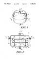
- FIG. 1shows in perspective a sensor in accordance with the present invention
- FIG. 2shows a sectional view of the sensor of FIG. 1;
- FIG. 3Ashows a top plan view of the fixed electrode of sensor of FIG. 1;
- FIG. 3Bshows a side plan view of the fixed electrode of the sensor of FIG. 1;
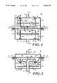
- FIGS. 4., 5 and 6show sectional views of alternative embodiments of the invention.
- FIGS. 1 and 2show a capacitive sensor 10 which includes a concave or cup-shaped base member 12 having a circular peripheral rim 14 lying in a plane (indicated by broken line 16 in FIG. 1) and extending symmetrically about a reference axis 10a.
- the base memberincludes three apertures 18 (two apertures 18 are shown in FIG. 1) equiangularly dispersed about axis 10a and a pressure port 19 is positioned along axis 10a.
- the base memberis made of stamped sheet metal, preferably stainless steel, although other metals or alloys and constructions techniques may be used.
- a relatively thin, deformable conductive diaphragm 20stretches across the base member 12 so that its peripheral edge overlie the rim 14.
- the diaphragm 20may be made of stainless steel, having a thickness in the range of 0.0002 to 0.030 inches.
- the diaphragm 20have the form disclosed in U.S. Pat. No. 4,434,203.
- the diaphragmmay be a metal foil, or a non-conductive material having a conductive portion, for example, established by a deposited conductive film.
- a concave or cup-shaped housing 24is positioned over the diaphragm 20.
- Housing 24includes a pressure port 26 and a peripheral flange 28 that is folded, or crimped, to the peripheral rim 14 of the base member in a manner capturing the peripheral edge of the diaphragm 20 with diaphragm 20 forming a planar and sheet, and providing an air tight seal at that edge.
- two distinct regions of interest 30 and 32are established; the first region 30 is below diaphragm 20 as shown in FIG. 2 and the second region 32 is above diaphragm 20 as shown in FIG. 2.
- the two regionsmay be separately pressurized by couplings attached to pressure ports 19 and 26 to establish a pressure differential across diaphragm 20.
- the central portion of diaphragm 20is movable in the direction of axis 10 in response to that pressure differential.
- Electrode assemblyis positioned within region 30.
- the electrode assemblyincludes an electrode element 42 and fixture elements 44 for holding electrode element 42 in place within region 30.
- Element 42is preferably a metal-stamped element shown in FIGS. 3A and 3B, having a substantially planar disk-shaped central portion 46 with three downwardly (as shown in FIG. 2) extending leg portions 48.
- each of legs 48is progressively narrowed at shoulder regions 48A and 48B.
- the region 46establishes an electrically conductive element opposite and nominally separated by a distance d from the central region of diaphragm 20.
- the region 46has a substantially planar top (as shown in FIG. 2) surface, but in some forms of the invention that surface may be curved to match the anticipated curve of the diaphragm 20 when deflected or deformed (for example, by a pressure differential), and still be within the meaning of the term "substantially planar" as used herein.
- fixture elements 44rigidly hold those distal tips 48a in place so that the top surface 46a of portion 46 is substantially parallel to and nominally a predetermined distanced from plane 16.
- fixture elements 44are formed from a matched (to base member 12) temperature coefficient, dielectric bonding material (thereby electrically insulating electrode 42 from diaphragm 20) such as epoxy, glass or other plastic material which is cured in place thermally or through catalytic reaction, and is transformed from a fluid state to a solid state.
- the fixture elements 44provide the dual functions of positioning the electrode 42 precisely relative to the rim of the base member, as well as provide the required insulation.
- the fixture elements 44may be made of stycast epoxy, manufactured by Emerson Cummings division of Grace Chemical Corporation.
- the capacitance across the dielectric fixture elements 44represent a parallel, inactive capacitance between the diaphragm 20 and the electrode 42, its effect is to dilute the active capacitance variation between the diaphragm 20 and the electrode 42 caused by pressure. For optimal performance, it is important that this leakage capacitance be reduced to a minimum. This objective is accomplished by the reduced cross sectional area at the distal tips 48a of the legs 48.
- the insulation material forming fixture elements 44cause minimum relative motion between the electrode and main housing. It is well known that the thermal coefficient of expansion for metallic material is often different substantially from that of a dielectric material.
- the shear joint configuration as described aboveminimizes the position shift of the electrode 42 relative to the base member 12. Under varying temperature conditions, the stress in the joint may change, but there will be substantially no net relative movement between the electrode 42 and the base member 12.
- the dielectric constant of the insulation material of fixture elements 44is preferably relatively insensitive to temperature and humidity.
- the insulation materialincorporates particles of powder of certain stable dielectric materials, such as alumina powder. This powder filler controls the thermal properties of the joining material. It also reduces the moisture absorption of the bonding material.
- the fixture elements 44form a strong and stable bond between legs 48 and base member 12, by virtue of the shear joint established between distal tips 48a and the tubular inner contour of holes 19.
- the electrode 42 and base member 14form a very stable and rigid structure which resists effects of shock and vibration in all directions.
- a capacitive pressure sensoris established, where the diaphragm 20 and portion 46 of electrode 42 effectively establish a "parallel" plate capacitor having a characteristic capacitance which varies inversely with d (which value is related to the pressure differential across the diaphragm 20).
- a further advantageis the ease and low cost techniques that may be used to assemble the sensor 10. More particularly, after separately forming elements 12 and 42.
- the electrode 42may be placed with surface 46a facing downward on shims of thickness d o supported on a planar worksurface (where d o corresponds to the desired zero deflection separation of diaphragm 20 from surface 46a).
- base member 12may be inverted and placed over electrode 42 with the legs 48 extending through holes 19.
- the bonding materialis then applied and cured to establish fixture elements 44.
- the combined electrode and base member configurationmay be inverted and the diaphragm 20 may be fixed in place together with housing member 24 to complete the assembly, without need for special milling or finish.
- an electronic circuit 60may be integrally included within the region 30 of sensor 10. As shown in FIG. 2, the circuit 60 may be positioned on a printed circuit board 62 which is supported (at shoulder regions 48a) by legs 48.
- the circuit 60is connected to electrode 42 and diaphragm 20 via leads 60a and 60b respectively, and includes an output lead 64 which passes via a feed-through function 66 to regions external to sensor 10.
- FIG. 4shows a sensor 10A that is similar to sensor 10 of FIG. 2 but where the housing 24 has been replaced by an assembly similar to base member 12 and electrode 42.
- elements corresponding to elements in FIG. 2are denoted by the same and primed (') reference designations.
- Such push-pull sensorsare useful in known prior art circuit configurations, for example, as exemplified by those set forth in U.S. Pat. No(s). 4,386,312 and 4,054,833, assigned to the assignee of the present invention.
- FIGS. 5 and 6show embodiments 110 and 110' of the invention that are generally similar to the embodiments of FIGS. 2 and 4, respectively, with corresponding elements being identified with similar reference designations.
- a housing member 80 (and 80')extends from rim 14 about the exterior of base member 12 (and 12').
- port 19 (and 19') and leads 64 (and 64')extend through apertures in housing member 80 (and 80').
- base member 12 (and 12') and diaphragm 20define the boundary of the region 30, while the housing member 80 (and 80') establish a protective outer housing.
- the circuit 60 and board 62are in the region within housing member 80 (and 80') but exterior to region 30.
- FIGS. 5 and 6are less sensitive to thermal transients than those of FIGS. 2 and 4. For example, when the environmental change of temperature occurs very rapidly for the configurations of FIG. 2 and 4, there is a lag of temperature change between the legs of the electrode 42 (and 42') and the base member 12 (and 12'). This temperature differential can cause the capacitance to change momentarily. This type of transient thermal response is reduced greatly by the introduction of the housing member 80 (and 80') in the configurations of FIGS. 5 (and 6). In the latter configurations, not only are the legs of the electrode 42 much shorter compared to those in the configuration of FIGS. 2 and 4, but they are also protected by the housing member 80 (and 80') and will not respond rapidly when the temperature exterior to the sensor is changed.
Landscapes
- Engineering & Computer Science (AREA)
- Power Engineering (AREA)
- Microelectronics & Electronic Packaging (AREA)
- Physics & Mathematics (AREA)
- General Physics & Mathematics (AREA)
- Measuring Fluid Pressure (AREA)
Abstract
Description
Claims (15)
Priority Applications (1)
| Application Number | Priority Date | Filing Date | Title |
|---|---|---|---|
| US07/723,372US5150275A (en) | 1991-07-01 | 1991-07-01 | Capacitive pressure sensor |
Applications Claiming Priority (1)
| Application Number | Priority Date | Filing Date | Title |
|---|---|---|---|
| US07/723,372US5150275A (en) | 1991-07-01 | 1991-07-01 | Capacitive pressure sensor |
Publications (1)
| Publication Number | Publication Date |
|---|---|
| US5150275Atrue US5150275A (en) | 1992-09-22 |
Family
ID=24905961
Family Applications (1)
| Application Number | Title | Priority Date | Filing Date |
|---|---|---|---|
| US07/723,372Expired - LifetimeUS5150275A (en) | 1991-07-01 | 1991-07-01 | Capacitive pressure sensor |
Country Status (1)
| Country | Link |
|---|---|
| US (1) | US5150275A (en) |
Cited By (39)
| Publication number | Priority date | Publication date | Assignee | Title |
|---|---|---|---|---|
| US5343766A (en)* | 1992-02-25 | 1994-09-06 | C & J Industries, Inc. | Switched capacitor transducer |
| US5442962A (en)* | 1993-08-20 | 1995-08-22 | Setra Systems, Inc. | Capacitive pressure sensor having a pedestal supported electrode |
| US5584708A (en)* | 1994-02-14 | 1996-12-17 | The Whitaker Corporation | Straddle electrical connector |
| US5705751A (en)* | 1995-06-07 | 1998-01-06 | Setra Systems, Inc. | Magnetic diaphragm pressure transducer with magnetic field shield |
| US5911162A (en)* | 1997-06-20 | 1999-06-08 | Mks Instruments, Inc. | Capacitive pressure transducer with improved electrode support |
| FR2775075A1 (en)* | 1998-02-18 | 1999-08-20 | Theobald Sa A | Differential pressure transducer of the double differential capacitor type |
| US5965821A (en)* | 1997-07-03 | 1999-10-12 | Mks Instruments, Inc. | Pressure sensor |
| US6029525A (en)* | 1998-02-04 | 2000-02-29 | Mks Instruments, Inc. | Capacitive based pressure sensor design |
| EP1153276A4 (en)* | 1999-01-22 | 2002-06-19 | Setra Systems Inc | Transducer having temperature compensation |
| WO2002014821A3 (en)* | 2000-08-11 | 2002-08-15 | Mks Instr Inc | Capacitive based pressure sensor design |
| US6568274B1 (en) | 1998-02-04 | 2003-05-27 | Mks Instruments, Inc. | Capacitive based pressure sensor design |
| US20040035211A1 (en)* | 1999-08-06 | 2004-02-26 | Pinto Gino A. | Capacitive pressure sensor having encapsulated resonating components |
| US20040102912A1 (en)* | 2002-11-26 | 2004-05-27 | Lav Ivanovic | Automatic calibration of a masking process simulator |
| US6772640B1 (en) | 2000-10-10 | 2004-08-10 | Mks Instruments, Inc. | Multi-temperature heater for use with pressure transducers |
| US20040226382A1 (en)* | 2003-05-16 | 2004-11-18 | Lischer D. Jeffrey | Contaminant deposition control baffle for a capacitive pressure transducer |
| US6828801B1 (en)* | 2001-10-26 | 2004-12-07 | Welch Allyn, Inc. | Capacitive sensor |
| US20050199070A1 (en)* | 2004-03-12 | 2005-09-15 | Denso Corporation | Electrical shield structure for pressure sensor |
| US20050229710A1 (en)* | 2003-08-11 | 2005-10-20 | O'dowd John | Capacitive sensor |
| US20060065973A1 (en)* | 2004-09-29 | 2006-03-30 | Loadstar Sensors, Inc. | Gap-change sensing through capacitive techniques |
| US7023684B1 (en)* | 2005-06-01 | 2006-04-04 | Jack Chen | Variable position sensor employing capacitance |
| US20060236773A1 (en)* | 1999-07-19 | 2006-10-26 | Nate Coleman | Planar ring and blister diaphragm for improved diaphragm-type pressure sensor |
| US7137301B2 (en) | 2004-10-07 | 2006-11-21 | Mks Instruments, Inc. | Method and apparatus for forming a reference pressure within a chamber of a capacitance sensor |
| US7141447B2 (en) | 2004-10-07 | 2006-11-28 | Mks Instruments, Inc. | Method of forming a seal between a housing and a diaphragm of a capacitance sensor |
| US20060267321A1 (en)* | 2005-05-27 | 2006-11-30 | Loadstar Sensors, Inc. | On-board vehicle seat capacitive force sensing device and method |
| US7201057B2 (en) | 2004-09-30 | 2007-04-10 | Mks Instruments, Inc. | High-temperature reduced size manometer |
| US7204150B2 (en) | 2005-01-14 | 2007-04-17 | Mks Instruments, Inc. | Turbo sump for use with capacitive pressure sensor |
| US20070205776A1 (en)* | 2006-03-01 | 2007-09-06 | Loadstar Sensors, Inc. | Cylindrical capacitive force sensing device and method |
| US20070227257A1 (en)* | 2006-04-03 | 2007-10-04 | Loadstar Sensors, Inc. | Multi-zone capacitive force sensing device and methods |
| US7284439B2 (en) | 1997-12-22 | 2007-10-23 | Mks Instruments, Inc. | Method for producing a pressure sensor for detecting small pressure differences and low pressures |
| US7353713B2 (en) | 2003-04-09 | 2008-04-08 | Loadstar Sensors, Inc. | Flexible apparatus and method to enhance capacitive force sensing |
| US20090015269A1 (en)* | 2007-07-13 | 2009-01-15 | Pinto Gino A | Stray Capacitance Compensation for a Capacitive Sensor |
| US20090255343A1 (en)* | 2008-04-09 | 2009-10-15 | Nagano Keiki Co., Ltd. | Physical quantity sensor and method for manufacturing the same |
| US20120167659A1 (en)* | 2011-01-05 | 2012-07-05 | Nxp B.V. | Pressure sensor with pressure-actuated switch |
| US8397578B2 (en) | 2010-06-03 | 2013-03-19 | Medtronic, Inc. | Capacitive pressure sensor assembly |
| US20130307567A1 (en)* | 2009-12-08 | 2013-11-21 | Magna Closures Inc. | Wide activation angle pinch sensor section |
| US9194760B2 (en) | 2013-03-14 | 2015-11-24 | Dwyer Instruments, Inc. | Capacitive pressure sensor with reduced parasitic capacitance |
| US9737657B2 (en) | 2010-06-03 | 2017-08-22 | Medtronic, Inc. | Implantable medical pump with pressure sensor |
| US10060172B2 (en) | 2015-08-21 | 2018-08-28 | Magna Closures Inc. | Variable resistance conductive rubber sensor and method of detecting an object/human touch therewith |
| US11385119B2 (en)* | 2019-11-14 | 2022-07-12 | Sensata Technologies, Inc. | Sensor apparatus having a crimped housing and a method of assembling the same |
Citations (3)
| Publication number | Priority date | Publication date | Assignee | Title |
|---|---|---|---|---|
| US4084438A (en)* | 1976-03-29 | 1978-04-18 | Setra Systems, Inc. | Capacitive pressure sensing device |
| US4168518A (en)* | 1977-05-10 | 1979-09-18 | Lee Shih Y | Capacitor transducer |
| US4358814A (en)* | 1980-10-27 | 1982-11-09 | Setra Systems, Inc. | Capacitive pressure sensor |
- 1991
- 1991-07-01USUS07/723,372patent/US5150275A/ennot_activeExpired - Lifetime
Patent Citations (3)
| Publication number | Priority date | Publication date | Assignee | Title |
|---|---|---|---|---|
| US4084438A (en)* | 1976-03-29 | 1978-04-18 | Setra Systems, Inc. | Capacitive pressure sensing device |
| US4168518A (en)* | 1977-05-10 | 1979-09-18 | Lee Shih Y | Capacitor transducer |
| US4358814A (en)* | 1980-10-27 | 1982-11-09 | Setra Systems, Inc. | Capacitive pressure sensor |
Cited By (58)
| Publication number | Priority date | Publication date | Assignee | Title |
|---|---|---|---|---|
| US5343766A (en)* | 1992-02-25 | 1994-09-06 | C & J Industries, Inc. | Switched capacitor transducer |
| US5442962A (en)* | 1993-08-20 | 1995-08-22 | Setra Systems, Inc. | Capacitive pressure sensor having a pedestal supported electrode |
| US5584708A (en)* | 1994-02-14 | 1996-12-17 | The Whitaker Corporation | Straddle electrical connector |
| US5705751A (en)* | 1995-06-07 | 1998-01-06 | Setra Systems, Inc. | Magnetic diaphragm pressure transducer with magnetic field shield |
| US5798462A (en)* | 1995-06-07 | 1998-08-25 | Setra Systems, Inc. | Magnetic position sensor with magnetic field shield diaphragm |
| US5911162A (en)* | 1997-06-20 | 1999-06-08 | Mks Instruments, Inc. | Capacitive pressure transducer with improved electrode support |
| US5965821A (en)* | 1997-07-03 | 1999-10-12 | Mks Instruments, Inc. | Pressure sensor |
| US7284439B2 (en) | 1997-12-22 | 2007-10-23 | Mks Instruments, Inc. | Method for producing a pressure sensor for detecting small pressure differences and low pressures |
| US7389697B2 (en) | 1997-12-22 | 2008-06-24 | Mks Instruments | Pressure sensor for detecting small pressure differences and low pressures |
| US6029525A (en)* | 1998-02-04 | 2000-02-29 | Mks Instruments, Inc. | Capacitive based pressure sensor design |
| US6568274B1 (en) | 1998-02-04 | 2003-05-27 | Mks Instruments, Inc. | Capacitive based pressure sensor design |
| WO1999042802A1 (en)* | 1998-02-18 | 1999-08-26 | A. Theobald S.A. | Differential pressure sensor |
| US6418793B1 (en)* | 1998-02-18 | 2002-07-16 | A Theobald Sa | Differential pressure sensor |
| FR2775075A1 (en)* | 1998-02-18 | 1999-08-20 | Theobald Sa A | Differential pressure transducer of the double differential capacitor type |
| EP1153276A4 (en)* | 1999-01-22 | 2002-06-19 | Setra Systems Inc | Transducer having temperature compensation |
| US20060236773A1 (en)* | 1999-07-19 | 2006-10-26 | Nate Coleman | Planar ring and blister diaphragm for improved diaphragm-type pressure sensor |
| US20040035211A1 (en)* | 1999-08-06 | 2004-02-26 | Pinto Gino A. | Capacitive pressure sensor having encapsulated resonating components |
| WO2002014821A3 (en)* | 2000-08-11 | 2002-08-15 | Mks Instr Inc | Capacitive based pressure sensor design |
| US6772640B1 (en) | 2000-10-10 | 2004-08-10 | Mks Instruments, Inc. | Multi-temperature heater for use with pressure transducers |
| US6992492B2 (en)* | 2001-10-26 | 2006-01-31 | Welch Allyn, Inc. | Capacitive sensor |
| US20050088184A1 (en)* | 2001-10-26 | 2005-04-28 | Welch Allyn, Inc. | Capacitive sensor |
| US6828801B1 (en)* | 2001-10-26 | 2004-12-07 | Welch Allyn, Inc. | Capacitive sensor |
| US20040102912A1 (en)* | 2002-11-26 | 2004-05-27 | Lav Ivanovic | Automatic calibration of a masking process simulator |
| US7353713B2 (en) | 2003-04-09 | 2008-04-08 | Loadstar Sensors, Inc. | Flexible apparatus and method to enhance capacitive force sensing |
| US6993973B2 (en) | 2003-05-16 | 2006-02-07 | Mks Instruments, Inc. | Contaminant deposition control baffle for a capacitive pressure transducer |
| US20040226382A1 (en)* | 2003-05-16 | 2004-11-18 | Lischer D. Jeffrey | Contaminant deposition control baffle for a capacitive pressure transducer |
| US20050229710A1 (en)* | 2003-08-11 | 2005-10-20 | O'dowd John | Capacitive sensor |
| US7353711B2 (en)* | 2003-08-11 | 2008-04-08 | Analog Devices, Inc. | Capacitive sensor |
| US20050199070A1 (en)* | 2004-03-12 | 2005-09-15 | Denso Corporation | Electrical shield structure for pressure sensor |
| US7171856B2 (en)* | 2004-03-12 | 2007-02-06 | Denso Corporation | Electrical shield structure for pressure sensor |
| US20060065973A1 (en)* | 2004-09-29 | 2006-03-30 | Loadstar Sensors, Inc. | Gap-change sensing through capacitive techniques |
| US7451659B2 (en) | 2004-09-29 | 2008-11-18 | Loadstar Sensors, Inc. | Gap-change sensing through capacitive techniques |
| US7201057B2 (en) | 2004-09-30 | 2007-04-10 | Mks Instruments, Inc. | High-temperature reduced size manometer |
| US7141447B2 (en) | 2004-10-07 | 2006-11-28 | Mks Instruments, Inc. | Method of forming a seal between a housing and a diaphragm of a capacitance sensor |
| US7624643B2 (en) | 2004-10-07 | 2009-12-01 | Mks Instruments, Inc. | Method and apparatus for forming a reference pressure within a chamber of a capacitance sensor |
| US7316163B2 (en) | 2004-10-07 | 2008-01-08 | Mks Instruments | Method of forming a seal between a housing and a diaphragm of a capacitance sensor |
| US7137301B2 (en) | 2004-10-07 | 2006-11-21 | Mks Instruments, Inc. | Method and apparatus for forming a reference pressure within a chamber of a capacitance sensor |
| US7204150B2 (en) | 2005-01-14 | 2007-04-17 | Mks Instruments, Inc. | Turbo sump for use with capacitive pressure sensor |
| US20060267321A1 (en)* | 2005-05-27 | 2006-11-30 | Loadstar Sensors, Inc. | On-board vehicle seat capacitive force sensing device and method |
| US7023684B1 (en)* | 2005-06-01 | 2006-04-04 | Jack Chen | Variable position sensor employing capacitance |
| US20070205776A1 (en)* | 2006-03-01 | 2007-09-06 | Loadstar Sensors, Inc. | Cylindrical capacitive force sensing device and method |
| US7570065B2 (en) | 2006-03-01 | 2009-08-04 | Loadstar Sensors Inc | Cylindrical capacitive force sensing device and method |
| US7343814B2 (en) | 2006-04-03 | 2008-03-18 | Loadstar Sensors, Inc. | Multi-zone capacitive force sensing device and methods |
| US20070227257A1 (en)* | 2006-04-03 | 2007-10-04 | Loadstar Sensors, Inc. | Multi-zone capacitive force sensing device and methods |
| US20090015269A1 (en)* | 2007-07-13 | 2009-01-15 | Pinto Gino A | Stray Capacitance Compensation for a Capacitive Sensor |
| US8096189B2 (en)* | 2008-04-09 | 2012-01-17 | Nagano Keiki Co., Ltd. | Physical quantity sensor and method for manufacturing the same |
| US20090255343A1 (en)* | 2008-04-09 | 2009-10-15 | Nagano Keiki Co., Ltd. | Physical quantity sensor and method for manufacturing the same |
| US20130307567A1 (en)* | 2009-12-08 | 2013-11-21 | Magna Closures Inc. | Wide activation angle pinch sensor section |
| US9234979B2 (en)* | 2009-12-08 | 2016-01-12 | Magna Closures Inc. | Wide activation angle pinch sensor section |
| US8397578B2 (en) | 2010-06-03 | 2013-03-19 | Medtronic, Inc. | Capacitive pressure sensor assembly |
| US9737657B2 (en) | 2010-06-03 | 2017-08-22 | Medtronic, Inc. | Implantable medical pump with pressure sensor |
| US10406281B2 (en) | 2010-06-03 | 2019-09-10 | Medtronic, Inc. | Implantable medical pump with pressure sensor |
| US11426514B2 (en) | 2010-06-03 | 2022-08-30 | Medtronic, Inc. | Implantable medical pump with pressure sensor |
| US20120167659A1 (en)* | 2011-01-05 | 2012-07-05 | Nxp B.V. | Pressure sensor with pressure-actuated switch |
| US9016133B2 (en)* | 2011-01-05 | 2015-04-28 | Nxp, B.V. | Pressure sensor with pressure-actuated switch |
| US9194760B2 (en) | 2013-03-14 | 2015-11-24 | Dwyer Instruments, Inc. | Capacitive pressure sensor with reduced parasitic capacitance |
| US10060172B2 (en) | 2015-08-21 | 2018-08-28 | Magna Closures Inc. | Variable resistance conductive rubber sensor and method of detecting an object/human touch therewith |
| US11385119B2 (en)* | 2019-11-14 | 2022-07-12 | Sensata Technologies, Inc. | Sensor apparatus having a crimped housing and a method of assembling the same |
Similar Documents
| Publication | Publication Date | Title |
|---|---|---|
| US5150275A (en) | Capacitive pressure sensor | |
| US5442962A (en) | Capacitive pressure sensor having a pedestal supported electrode | |
| US4388668A (en) | Capacitive pressure transducer | |
| US6205861B1 (en) | Transducer having temperature compensation | |
| US4207604A (en) | Capacitive pressure transducer with cut out conductive plate | |
| US4426673A (en) | Capacitive pressure transducer and method of making same | |
| EP0893676B1 (en) | Combined pressure responsive transducer and temperature sensor apparatus | |
| US4358814A (en) | Capacitive pressure sensor | |
| US4177496A (en) | Capacitive pressure transducer | |
| US4295376A (en) | Force responsive transducer | |
| US6122972A (en) | Capacitive pressure sensor with moving or shape-changing dielectric | |
| US4951174A (en) | Capacitive pressure sensor with third encircling plate | |
| US4562742A (en) | Capacitive pressure transducer | |
| US4879627A (en) | Differential capacitive pressure sensor with over-pressure protection | |
| US4703658A (en) | Pressure sensor assembly | |
| US5396803A (en) | Dual balanced capacitance manometers for suppressing vibration effects | |
| US4774626A (en) | Pressure sensor with improved capacitive pressure transducer | |
| KR20020044152A (en) | Capacitive pressure sensor | |
| JPH0526132B2 (en) | ||
| JPS6356935B2 (en) | ||
| GB1563894A (en) | Capacitive pressure transducer and method for making same | |
| EP3658877B1 (en) | Ceramic pressure sensor | |
| WO1998037393A1 (en) | A sensor element having temperature measuring means | |
| US5034848A (en) | Low pressure sensor | |
| EP0009313A1 (en) | Improved pressure transducer and assembly |
Legal Events
| Date | Code | Title | Description |
|---|---|---|---|
| AS | Assignment | Owner name:SETRA SYSTEMS, INC. A MA CORPORATION Free format text:ASSIGNMENT OF ASSIGNORS INTEREST.;ASSIGNORS:LEE, SHIH-YING;LI, SEN ZI;REEL/FRAME:005973/0618 Effective date:19910607 Owner name:SETRA SYSTEMS, INC., MASSACHUSETTS Free format text:ASSIGNMENT OF ASSIGNORS INTEREST;ASSIGNORS:LEE, SHIH-YING;LI, SEN ZI;REEL/FRAME:005973/0618 Effective date:19910607 | |
| STCF | Information on status: patent grant | Free format text:PATENTED CASE | |
| FPAY | Fee payment | Year of fee payment:4 | |
| FEPP | Fee payment procedure | Free format text:PAYOR NUMBER ASSIGNED (ORIGINAL EVENT CODE: ASPN); ENTITY STATUS OF PATENT OWNER: LARGE ENTITY | |
| FPAY | Fee payment | Year of fee payment:8 | |
| FEPP | Fee payment procedure | Free format text:PAT HOLDER NO LONGER CLAIMS SMALL ENTITY STATUS, ENTITY STATUS SET TO UNDISCOUNTED (ORIGINAL EVENT CODE: STOL); ENTITY STATUS OF PATENT OWNER: LARGE ENTITY | |
| REFU | Refund | Free format text:REFUND - PAYMENT OF MAINTENANCE FEE, 12TH YR, SMALL ENTITY (ORIGINAL EVENT CODE: R2553); ENTITY STATUS OF PATENT OWNER: LARGE ENTITY | |
| FPAY | Fee payment | Year of fee payment:12 |