US5148498A - Image coding apparatus and method utilizing separable transformations - Google Patents
Image coding apparatus and method utilizing separable transformationsDownload PDFInfo
- Publication number
- US5148498A US5148498AUS07/561,449US56144990AUS5148498AUS 5148498 AUS5148498 AUS 5148498AUS 56144990 AUS56144990 AUS 56144990AUS 5148498 AUS5148498 AUS 5148498A
- Authority
- US
- United States
- Prior art keywords
- image
- array
- frequency
- coefficients
- dimensional
- Prior art date
- Legal status (The legal status is an assumption and is not a legal conclusion. Google has not performed a legal analysis and makes no representation as to the accuracy of the status listed.)
- Expired - Lifetime
Links
Images


Classifications
- H—ELECTRICITY
- H04—ELECTRIC COMMUNICATION TECHNIQUE
- H04N—PICTORIAL COMMUNICATION, e.g. TELEVISION
- H04N19/00—Methods or arrangements for coding, decoding, compressing or decompressing digital video signals
- H04N19/60—Methods or arrangements for coding, decoding, compressing or decompressing digital video signals using transform coding
- H04N19/63—Methods or arrangements for coding, decoding, compressing or decompressing digital video signals using transform coding using sub-band based transform, e.g. wavelets
- H04N19/635—Methods or arrangements for coding, decoding, compressing or decompressing digital video signals using transform coding using sub-band based transform, e.g. wavelets characterised by filter definition or implementation details
- H—ELECTRICITY
- H03—ELECTRONIC CIRCUITRY
- H03H—IMPEDANCE NETWORKS, e.g. RESONANT CIRCUITS; RESONATORS
- H03H17/00—Networks using digital techniques
- H03H17/02—Frequency selective networks
- H03H17/0202—Two or more dimensional filters; Filters for complex signals
Definitions
- the present inventionrelates to data processing systems, and more particularly, to image compression apparatuses and methods.
- Imagesare conventionally represented by a two dimensional array of values in which each value represents a property of the image at a corresponding point on the image.
- each valuerepresents a property of the image at a corresponding point on the image.
- gray-scale imagesa single number representing the gradations of intensity from white to black, referred to as the gray scale, is stored.
- each "value"is a vector whose components represent the gradations in intensity of the various primary colors, or some alternative color code, at the corresponding point in the image.
- This representation of an imagecorresponds to the output of a typical image-sensing device such as a television camera. Such a representation is convenient in that it is easily regenerated on a display device such as a CRT tube.
- a display devicesuch as a CRT tube.
- ithas at least two shortcomings. First, the number of bits needed to represent the data is prohibitively large for many applications. Second, if the image is to be processed to extract features that are arranged in the same order of importance as that perceived by a person viewing the image, the amount of processing needed can be prohibitively large.
- the number of bits needed to store a typical imageis sufficiently large to limit the use of images in data processing and communication systems.
- a single 512 ⁇ 512 gray-scale image with 256 gray levelsrequires in excess of 256,000 bytes.
- a small-scale computer useris limited to disk storage systems having a capacity of typically 300 Mbytes. Hence, less than 1200 images can be stored without utilizing sone form of image compression.
- the transmission of images over conventional telephone circuitryis limited by the large number of bits needed to represent the image. If an 8 ⁇ 11 inch image were digitized to 256 gray levels at 200 dots per inch (the resolution utilized in typical FAX transmissions), in excess of 28 million bits would be required. Normal consumer-quality analog telephone lines are limited to a digital communication rate of 9600 bits per second. Hence, the transmission of the image would require in excess of 45 minutes in the absence of some form of image compression.
- the need to reduce the data required to represent an imagehas led to numerous image compression methods. These methods can be conveniently divided into two classes, invertible and non-invertible methods.
- the invertible methodsreduce redundancy but do not destroy any of the information present in the image.
- These methodstransform the two-dimensional array into a form requiring fewer bits to store.
- the original two-dimensional arrayis generated by the inverse transformation prior to display.
- the regenerated imageis identical to the original image.
- the imageconsists of a two-dimensional array of bits.
- a one-dimensional list of bitscan be generated from the two-dimensional array by copying, in order, each row of the two-dimensional array into the one-dimensional array. It has been observed that the one-dimensional array has long runs of ones or zeros.
- a run of 100 onesOne hundred bits are required to represent the run in the one-dimensional array.
- the same 100 bitscould be represented by a 7-bit counter value specifying the length of the run and the value "one" specifying the repeated gray level.
- the 100 bitscan be reduced to 8-bits. This is the basis of a transformation of the one-dimensional array in which the transformed image consisting of a sequence of paired values, each pair consisting of a count and a bit value.
- compression ratios of the order of 5 to 10can be obtained utilizing these methods.
- the gains obtaineddecrease rapidly as the number of gray levels is increased.
- the probability of finding repeated runs of the same gray leveldecreases.
- Each time the gray level changesa new pair of values must be entered into the file. As a result, compression ratios exceeding 3 are seldom obtained for invertible compression of gray-level images.
- the typical prior art non-invertible image compression methodscan be divided into two steps.
- the first steptwo sets of numerical coefficients, p i and q j , are derived from the image by fitting the image to a linear expansion of the form
- the basis functions F i and G jare chosen such that the most "important" information contained in the image is represented by the p's and the least inportant information is represented by the q's.
- the transformation in questionis invertible in the sense that given an N ⁇ N set of pixels I(x i ,y j ), one can determine a total of N 2 coefficients p i and q i that will exactly reproduce the N 2 values I(x i , y j ). Since there are N 2 pixels and N 2 coefficients, the set of coefficients requires the same number of bits to store as the image if the transform coefficients are stored to the same precision as the image pixel intensities. Hence, the transformation alone does not produce any compression of the image.
- the coefficients p i and q jare quantized.
- the number of bits used to represent each p iis greater than that used to represent each q j , since the p i represent the most important information in the image.
- the reduced precision utilized in the representation of the q j 's and p i 'sis the source of the non-invertibility of the transformation.
- the image transformationmust separate the information into coefficients having the property that the different sets of coefficients contain image information of different importance. If is known that the most subjectively important image information is contained in the low spatial frequency components of the image. Hence, the functions F i (x,y) must be limited in their spatial frequency response to lower frequencies than the functions G j (x,y). If this condition is satisfied, then the coefficients p i will represent more subjectively important information than the coefficients q j .
- a second problemoccurs with basis functions having large support.
- imagestend to contain structures whose spatial extent is small compared to the size of the image.
- To represent such a structure with basis functions that have support which is much larger than the structure in questionoften requires the superposition of many such basis functions.
- the number of coefficients which contain useful informationis likely to be larger if basis functions having support which is much larger than the objects found in the image are used.
- the quantization errorsare also related to the transform's ability to concentrate the essential image information into a set of coefficients which represents that information using the smallest number of bits.
- the number of bits needed to represent the imageis the sum of two numbers. First, bits must be allocated to communicate the values of the coefficients produced by the transform which are saved for use in reconstructing the image. The second number is the number of bits needed to communicate which of the possible coefficients were saved after transformation. For any given compression ratio, the total number of available bits for representing the compressed image is fixed. Bits used for labels are unavailable for storing coefficient values. Hence, if a significant number of bits are needed for storing the label information, the number of bits available for quantization will be significantly reduced. This reduction in bits used for quantization results in larger quantization errors.
- the transformation of an N ⁇ N imagecan produce N 2 coefficients.
- the coefficientscould be listed by giving a label specifying the identity of the coefficient and a number representing the value of the coefficient for each coefficient. If the transformation is effective, most of these coefficients will be zero or very small numbers.
- the minimum number of bits needed to represent the useful coefficients in this formatwould be the number needed to specify the label associated with each non-zero coefficient and the number of bits needed to adequately represent the value of that coefficient.
- One problem with this type of representationis the number of bits needed to communicate the labels.
- the transformation coefficients in questionshould form a subset whose identity does not depend on the specific image being transformed. In this case, the entire subset will be quantized. Since the position of a coefficient in the subset is equivalent to a label, there is no need to allocate bits for a label specifying the identify of each coefficient.
- Prior art methodsmake use of the observation that the most important information appears to be concentrated in the low spatial frequencies for images.
- the imageis typically transformed to produce one set of coefficients representing the low frequency information and a plurality of sets of coefficients representing different high spatial frequency information.
- the individual setsare then quantized with differing degrees of precision.
- the only labeling informationis then that required to identify the individual subsets. In this manner, the information needed to specify the "label" for each coefficient is reduced.
- one class of transformationsis based on the Fourier expansion for the image transformation.
- the Fourier series basis functionshave the advantage of providing an orthonormal basis for the image space.
- these functionshave a number of disadvantages.
- First, the support of every Fourier basis functionis the entire image. That is, each basis function is contributes to the entire image.
- quantization errorstend to produce aliasing errors which are subjectively unsatisfactory.
- Second, the computational work load to compute the Fourier transformis of order n log (n), where n is the number of pixels in the original image. To overcome this difficulty, the image is often divided into smaller sub-images which are pieced together after reconstruction. This procedure reduces the computational work load, but leads to other undesirable artifacts in the reconstructed image.
- this methodis equivalent to the transformation discussed above with the q j being further divided into different subsets.
- Adelson, et al.refer to their QMF method as being equivalent to expanding the image in an orthonormal basis set
- this methoddoes not provide the claimed orthonormal expansion.
- the basis functions corresponding to a QMFare, by definition, symmetric. Using this property of the QMF basis functions, it can be shown that the QMF basis functions can not be an orthonormal set. Hence, this method does not provide the advantages of an orthonormal transformation of the image.
- a still further problem with the method taught by Adelson, et al.is the inability to finely tune the compression ratio.
- Each time the filtering operation is appliedthe number of coefficients in the ⁇ p i ⁇ set decreases by a factor of four.
- FIG. 1is illustrates a typical prior art image compression system.
- FIG. 2is a block diagram of a prior art image encoding apparatus.
- FIG. 3illustrates how the apparatus shown in FIG. 2 may be used to provide compression ratios greater than 4.
- FIG. 4is a block diagram of an image encoding apparatus according to the present invention.
- FIGS. 5a-5cshow a block diagram of another embodiment of an image encoding apparatus according to the present invention.
- FIG. 6is a block diagram of an analyzer according to the present invention.
- FIG. 7is a block diagram of another embodiment of an image encoding apparatus according to the present invention.
- FIG. 8is a block diagram of an image reconstruction apparatus according to the present invention.
- FIG. 9is a block diagram of a synthesizer according to the present invention.
- FIG. 10is a block diagram of a coding apparatus according to the present invention for coding a general D-dimensional image.
- FIG. 11is a block diagram of a decoding apparatus according to the present invention for reconstructing a D-dimensional image.
- Table Iprovides examples of coefficients satisfying Equations 5(a), 5(b) and (6).
- the present inventionwill be described in terms of an image compression system; however, it will be apparent to those skilled in the art that the method may be utilized to compress any multi-dimensional data array.
- the present inventionmay be more easily understood in the context of an image compression system.
- FIG. 1Such a system is shown in FIG. 1.
- the systemincludes an image compression sub-system 10 and an image decompression sub-system 21.
- the image compression sub-system 10receives an image 11 and codes that image such that the coded version requires fewer bits to transmit than image 11.
- the coded imageis typically transmitted on a communication link 20 to the image decompression sub-system 21 which generates a reconstructed image 30 from the encoded image. Alternatively, the coded image may be stored for later play-back.
- Image compression sub-system 10typically includes four elements.
- An image transformer 12converts the original image into an array of transform coefficients 14.
- the transform coefficientsare the coefficients of a linear expansion of the image in a basis system such as that described above.
- the array of transform coefficients 14is then quantized by quantizer 16 to produce an array requiring fewer bits to store than array 14.
- the quantizationinvolves replacing each transform coefficient with an integer identifying the level in the quantization scheme corresponding to the transform value in question.
- the quantized coefficientsare coded by coder 18 which takes advantage of redundancies in the quantized transforms to further reduce the number of bits that must be transmitted. Redundancy coding and the like are well known to those skilled in the art and hence will not be discussed here.
- the reconstructed image 30is obtained by reversing the process.
- the coding introduced by coder 18is reversed by decoder 22 to produce a quantized array consisting of the integers representing the levels in the quantization scheme.
- the output of decoder 22is inputted to a dequantizer 24 which replaces each level by the corresponding transform value.
- the transform values provided by dequantizer 24are approximations to the original transform values in array 14.
- the resultant transform array 26is then converted to reconstructed image 30 by applying the inverse of the transformation utilized in transformer 12. This inversion is carried out by inverse image transformer 28.
- the improvements provided by the present inventionare primarily the result of improvements in image transformer 12 and its corresponding inverse image transformer 28.
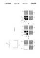
- the improvements provided by the present inventionmay be more easily comprehended by a comparison to a typical prior art image transformation system. Such a system is shown in FIG. 2 at 40.
- the transformation systemis essentially that taught by Adelson, et al. in U.S. Pat. No. 4,817,182.
- transformation system 40operates on an N ⁇ N pixel image 42.
- Image 42may be viewed as consisting of N rows having N pixels per row.
- the transformationis accomplished in two stages. In the first stage, each row is transformed by an analyzer 44 to produce two linear arrays 46 and 48 representing the low and high frequency information, respectively, in the row.
- the arrayscontain the coefficients corresponding to one-dimensional basis functions in a linear expansion of the function represented by each row.
- analyzer 44comprises a quadrature mirror filter bank (QMF). Each row is treated as a "digital signal" which is filtered by the QMF.
- QMFquadrature mirror filter bank
- the low frequency array corresponding to each rowis stored in a corresponding location in a first array labeled as L in FIG. 2.
- the high frequency array corresponding to each rowis stored in a corresponding location in a second array labeled as H in FIG. 2.
- the L and H arrayseach consist of N rows having N/2 coefficients per row.
- each of the L and H arraysis further transformed.
- Each arrayis viewed as comprising N/2 columns having N elements per column.
- Each columnis analyzed by an analyzer 44 to generate first and second arrays analogous to those described above with reference to each row.
- the resultant linear arraysare stored in corresponding locations in four arrays LL, LH, HL and HH.
- the low and high frequency arrays generated from the columns in the L arrayare stored in array LL and LH, respectively.
- the low and high frequency arrays generated from the columns in the H arrayare stored in array HL and HH, respectively.
- Each of the four arrays LL, LH, HL, and HHhas one quarter the number of elements of the original array 42.
- the LL c i ,jare the coefficient values in the LL array; the LH c i ,j are the coefficient values in the LH array; the HL c i ,j are the coefficient values in the HL array, and the HH c i ,j are the coefficient values in the HH array.
- the corresponding basis function LL F i ,j (x,y), LH F i ,j (x,y), and HH F i ,j (x,y)may be calculated from a knowledge of the functions used in the QMF filters used in analyzer 44.
- Analyzer 44produces a one-dimensional decomposition of the input signal S(x) into a series involving basis functions L R k (x) and H R k (x) and coefficients L b k and H b k according to the relationship
- the set of coefficients L b kare the coefficients comprising array 46
- the set of coefficients H b kare the coefficients comprising array 48.
- the basis functions LL F i ,j (x,y), LH F i ,j (x,y), HL F i ,j (x,y), and HH F i ,j (x,y)may be written in terms of the functions L R k (x) and H R k (x); however, as will be discussed in detail below, the various coefficient arrays can be calculated without explicitly evaluating the functions in question.
- the transformation shown in Eq. (1)generates four arrays of coefficients, each array having one fourth the number of entries of the original image.
- the LL arraycomprises lower frequency information than the other arrays.
- the lower frequency informationis more important to human viewers.
- only the coefficients of the LL arraywould be quantized. That is, zero bits would be allocated for each of the coefficients in the LH, HL, and HH arrays. If the coefficients in the LL array are quantized using the same number of bits per coefficient that are used to represent the various pixel elements in the original image, then a compression ratio of 4:1 would be obtained.
- the ratio of the number of pixels in the original image to the number of low frequency coefficientsis the simple compression ratio. This is the compression ratio that would be obtained if the low frequency coefficients were quantized to the same precision as the original pixels and the other coefficients were allocated zero bits.
- the example discussed aboveresults in a simple compression ratio of 4.
- FIG. 2illustrates the apparatus shown in FIG. 2 and the image transformation discussed above.
- image transformation discussed abovecan be iterated to produce simple compression ratios of 4 k , where k is any positive integer.
- FIG. 3illustrates the transformation of an image 72 into sets of coefficients having a simple compression ratio of 64.
- Image 72is first input to image transformer 40 which generates four sets of coefficients 74-77 as described above with reference to FIGS. 1 and 2. Each set of coefficients has one fourth the number of elements of image 72.
- Coefficient set 74is the LL set. The iteration is accomplished by treating the LL set from the previous transformation as an image which is then inputted to image transformer 40. Hence, coefficient set 74 is inputted to image transformer 40 which produces four new sets of coefficients 80-83. Each of these has one fourth the number of elements that were present in coefficient set 74. Hence, each of the coefficient sets 80-83 has 1/16th the number of elements of the original image.
- Coefficient set 80is the LL coefficient set. Hence, it contains the information specifying the lowest spatial frequencies in the image.
- Coefficient sets 81-83represent information which is intermediate in frequency between that represented by coefficient set 80 and that represented by coefficient sets 75-77.
- coefficient set 80as input to image transformer 40 thereby producing coefficients 84-87.
- Each of these setshas one fourth the number of coefficients that were present in coefficient set 80.
- coefficient set 84 which comprises the LL sethas 1/64th the number of coefficients of the original image.
- An image transformer according to the present inventionprovides a means for transforming an image to provide simple compression ratios of M 2k where M is any integer greater than 1.
- An image transformer according to the present inventionutilizes a new type of digital filter.
- the prior art image transformation systemsutilize a QMF to process each row (or column) of an image array to produce two transformed rows having one half the number of elements as the original row.
- the transformationresults in four arrays, each array having one fourth the number of elements of the original image array. This yields a simple compression ratio of 4. To obtain higher simple compression ratios, the transformation must be iterated.
- An image transformerutilizes a filter that operates on each row (or column) of the image array to generate M output arrays.
- Each output arrayhas approximately 1/M the number of elements of the original row (or column). One of these represents the low-frequency information in the row (or column); the others represent different forms of high-frequency information.
- Image array 402is preferably a conventional memory array having rows and columns.
- image array 402contains N columns and N rows.
- Nis divisible by M.
- the imagemay be "padded" to create an image in which the new N is divisible by M.
- Embodiments in which the number of rows differ from the number of columnwill be apparent to those skilled in the art.
- each row of image array 402is converted to M sets of coefficients by analyzer 404.
- the output of analyzer 404comprises M output linear arrays each having a length of N/M in the preferred embodiment of the present invention. Cases in which the length is slightly greater than this will be discussed in more detail below.
- Each output linear arraycomprises a set of coefficients representing different frequency information from the row in image array 402 that is being processed.
- Output linear array 406represents the low-frequency information.
- the other (M-1) output linear arraysrepresent various types of high-frequency information. Exemplary output arrays having high frequency information are shown at 408 and 410. A more detailed explanation of the type of information in the high-frequency output arrays will be provided below.
- Each of the output linear arraysis stored in a corresponding row array.
- the low-frequency output linear array 406is stored in row 421 of array 420 thereof.
- High-frequency linear array 408is stored in row 431 of row array 430, and high-frequency linear array 410 is stored in row 441 of row array 440.
- each of the row arraysis treated as a plurality of columns and analyzed in a manner analogous to that described above with reference to the rows of image array 402.
- column 422 of row array 420is inputted as a linear array to analyzer 450 which generates M output arrays, output array 451 representing the low-frequency and the other M-1 output arrays representing the high-frequency information.
- Exemplary high-frequency output arraysare shown at 452 and 453.
- each output arrayhas N/M elements.
- Each output arrayis stored in a corresponding column of a corresponding image output array.
- Low-frequency output array 451is stored in column 455 of image output array 454.
- High-frequency output array 452is stored in column 457 of output image array 456, and high-frequency output array 453 is stored in column 459 of output image array 458.
- the columns of row arrays 430are treated in a like manner, the columns of row array 430 being processed by analyzer 460 to generate M output image arrays of which output image arrays 464, 466, and 468 are examples.
- the elements in these output arrays corresponding to elements discussed above with reference to analyzer 450have been given similar numbers in the FIG. 4 and will not be discussed further.
- row array 440is processed by analyzer 470. Again, the elements in the output arrays corresponding to elements discussed above with reference to analyzer 450 have been given similar numbers in the FIG. 4 and will not be discussed further.
- Output image array 454contains the low-frequency information from image array 402.
- the remaining output image arrayscontain various forms of high-frequency information.
- any desired simple image compression ratio which is the square of an integercan be provided by the present invention either by selecting an appropriate M or by iterating the image transformation utilizing transformations.
- the image transformationcan be repeated using low-frequency output image array 454 as the input. If the first application of transformation utilizes an analyzer generating M 1 output arrays and the second application utilizes an analyzer having M 2 output arrays, then the combined transformation will have a simple compression ratio of (M 1 M 2 ) 2 .
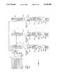
- FIG. 5(a)-(c)An embodiment of an image transformer according to the present invention which utilizes a single memory array is shown in FIG. 5(a)-(c). Referring to FIG. 5(a), the image is stored initially in image array 502 which is used to store both the row arrays and the output image arrays. Elements of this embodiment of the present invention which serve analogous functions to the embodiment shown in FIG. 4 are labeled with like numbers.
- FIG. 5(a)illustrates the transformation of row 501 in image array 502.
- linear output arraysare stored in the row of image array 502 from which they were derived.
- Linear output array 506is stored at 521;
- linear output array 508is stored at 531, and
- linear output array 510is stored at 541.
- image array 502is then processed by columns as shown in FIG. 5(b). Each column is processed by analyzer 550 to produce M linear output arrays, a linear low frequency array 551 and M-1 linear high frequency arrays. Exemplary linear high frequency arrays are shown at 552 and 553.
- FIG. 5(b)illustrates the transformation of column 522.
- image array 502comprises M 2 image output arrays, a low frequency image output array 554 and (M 2 -1) high frequency output arrays.
- Exemplary image output arrays corresponding to the exemplary image output arrays shown in FIG. 4are shown in FIG. 5(c). Like image output arrays are numbered with similar numbers.
- FIG. 5utilizes different analyzers for processing the rows and columns, it will be apparent to those skilled in the art that the same analyzer may be utilized for both processing operations.
- the preferred embodiment of the present inventionutilizes special purpose hardware for performing an image transformation, it will also be apparent to those skilled in the art that the present invention may be practiced on a general purpose digital computer.
- the labels "row” and "column” in the above descriptioncan be interchanged.
- the present inventionwould operate equally well if the columns of the image were first filtered to provide column arrays. In this case, each row of each column array would then be filtered in the second stage of the image transformation.
- Analyzer 600provides a low frequency output array and M-1 high frequency output arrays.
- Analyzer 600comprises M finite impulse response (FIR) filters: one low frequency FIR filter 602 and (M-1) high frequency FIR filters. Exemplary high frequency FIR filters are shown at 604 and 606.
- FIRfinite impulse response
- the FIRsutilize digital filtering techniques.
- Each filterreceives an input signal comprising a linear array of values which are either a row of pixel values or values resulting from the filtering of a row of pixel values.
- Each FIRcomprises a means for convolving the input signal with a set of filter coefficients to provide an output signal. If the input signal consists of an array of values S j then the output of each filter consists of an array of values v p where
- the (*)indicates complex conjugation.
- a different set of coefficientsis used for each filter.
- the superscript "i”is used to denote the filter in question.
- the remaining (M-1) superscript valueswill be used to denote the coefficients used by the high frequency filters.
- the summation in Eq. (3)runs over all of the k values for which i a* k is non-zero. The manner in which the coefficients are determined will be discussed in detail below.
- Mis referred to as the multiplier of the transformation.
- the number of non-zero output values i v pwill depend on the treatment of the edge of the image.
- S jI q ,j. That is, S is the q th row of the image.
- the input signalcomprises a sequence of digital values which are consecutively shifted into each filter. Since each output value i v p depends on a plurality of input values, the filters must have sufficient memory to store the previously received values needed for the calculation. The number of values which must be stored depends on the number of non-zero filter coefficients.
- each filteris constructed from a dedicated convolution circuit having sufficient memory to store the required values. As each i v p is generated, it is shifted into the corresponding linear output array.
- the FIR filtering operationsmay be carried out by a general purpose digital computer.
- Each filtercan be replaced by a computer, or a single computer can be used to calculate the outputs. If this later embodiment is used, however, the time needed to filter the signal may become prohibitively long for some applications.
- the filtering operation carried out by an analyzer according to the present inventionis equivalent to expanding a function S(x) having values S j on a set of discrete grid points ⁇ x j ⁇ in a linear series of the form
- the functions, 0 R k (x)are the low frequency basis functions and the functions, i R k (x), are the high frequency basis functions corresponding to the i th filter.
- the coefficients i b kare the values outputted by the i th filter.
- the filter coefficientsmust satisfy the following relation for the filters to provide high and low-frequency filtering:
- i and jare any integers between 0 and (M-1) inclusive and q is any integer.
- basis functions having small supportare related to the number of coefficients i a p that are non-zero.
- utilizing basis functions with small supportalso reduces the computational workload.
- the computational workloadis proportional to the number of non-zero i a p .
- basis functions which approximate polynomialsplaces a lower limit on the size of the support of the basis functions. It can be shown that the minimum number of non-zero filter coefficients for which the corresponding basis functions approximate second order polynomials is 3M. Since second order polynomials are the lowest order polynomials that can approximate curved surfaces, 3M is the preferred value for the number of coefficients.
- Each of the filters in analyzer 600 shown in FIG. 6is preferably constructed from a digital circuit for carrying out the computation shown in Eq. (5). Special purpose circuitry for carrying out such convolution calculations is well known to the signal processing arts, and hence, will not be discussed in detail here.
- the various filterswork in parallel. However, it will be apparent to those skilled in the art that a single digital computer could be used for simulating the parallel filter arrangement shown in FIG. 6.
- the imagewas initially stored in a memory such as image array 402 shown in FIG. 4. However, such an initial storage of the image is not necessary.
- An embodiment of the present invention which avoids the initial storageis shown in FIG. 7.
- the image 700 to be codedis input to analyzer 704 one row at a time.
- Analyzer 704may receive the image from a central memory or over a communication link.
- the imageis received through an input port 701.
- analyzer 704generates M sets of image coefficients representing the information in different spatial frequencies in the row. Exemplary sets of coefficients are shown stored in registers at 706 and 710.
- Controller 711also includes memory for storing the various sets of filter coefficients used by analyzer 720 to generate the image coefficients.
- a column analyzer 750When the entire image has been received and image coefficients generated therefrom, a column analyzer 750 operates on each column of each row array to produce the final coding of the image.
- the particular column being analyzed at any given timeis determined by gate circuit 744 which is also under the control of controller 711. Controller 711 also stores the filter coefficients used by the column analyzers in generating image coefficients from the columns in question.
- Each column analyzerpreferably generates M sets of image coefficients using the same filter coefficients as used by analyzer 704. However, embodiments in which different sets of filter coefficients and different numbers of sets of image coefficients are generated for the rows and columns will be apparent to those skilled in the art.
- Each set of image coefficients generated by the column analyzer 750is stored in a corresponding register. Exemplary registers are shown at 751 and 753. These registers are coupled to an output port 780. As each column is processed, the image coefficients are read out in a predetermined order through output port 780 which is under the control of controller 711. Controller 711 also receives signals from external devices which coordinate its activities with those devices. For simplicity, the connections to the external devices have been omitted from the figure.
- the registers connected to the row analyzer 704 and column analyzer 750preferably comprise two sets of storage locations. At any given time, one set of locations is being filled with image coefficients which are being generated by the attached analyzer. At the same time, the other set of locations is being read out either into a row array or output port 780.
- the time needed to code an image using the present inventionis essentially equal to that needed to read the image into the one row at a time and read out the final coefficients. This latter time is also approximately the needed to read in the image.
- the present inventionis to be utilized in an image compression system in which not all of the high-frequency image coefficients are to be saved, then the corresponding memory arrays and analyzers may be omitted. In addition, some of the filters in the remaining analyzers may also be omitted.
- FIG. 7utilizes two analyzers and gate circuits
- the embodiment shown in FIG. 7may be simulated on a digital computer.
- the row memorieswould comprise regions of the computer's storage system, and the analyzers would be simulated by computer programs.
- the various gate circuitswould comprise the memory address circuitry.
- the present inventionis better adapted to parallel computation than analogous prior art devices.
- the apparatus taught by Adelson, et al.must be iteratively applied to obtain simple image compression ratios greater than 4.
- a simple image compression ratio equal to 64is required. This is obtained by first analyzing the image to produce a first set of image coefficients comprising four sets of coefficients, each being one fourth the size of the image.
- the low-frequency set of image coefficientsmust then be re-analyzed generating a second set of image coefficients comprising four new sets of coefficients, each being 1/16 th the size of the original image.
- the low-frequency image coefficient set from this second setmust be analyzed to produce a third set of coefficients comprising 4 sets of image coefficients, each being 1/64 th the size of the original image.
- each iterationoperates on the low-frequency image coefficients generated by the previous set of coefficients. Hence, the various iterations may not be carried out in parallel to reduce the overall computation time.
- the present inventionwould accomplish an image coding with a simple compression ratio of 64 in a single pass.
- Each analyzerwould include 8 convolution circuits working in parallel.
- the conversion of the image to the coefficients in the row arrayscan be carried out as fast as the image can be received if an embodiment such as that described above with dual registers is utilized.
- each columncan be processed a column analyzer having dual registers and 8 convolution circuits in a time which is approximately equal to the time needed to read the column from the row array. This is essentially the same time as needed by the apparatus taught by Adelson, et al. to generate the first set of image coefficients.
- the present inventionrequires significantly less memory than the apparatus taught by Adelson, et al. If simple compression ratios greater than 4 are needed, then the prior art devices require the generation of the first set of image coefficients in which each row is converted to a low-frequency set of coefficients having one half the number of elements as the original row. Thus, even if all of the high-frequency coefficients are to be discarded, the device taught by Adelson, et al. requires a memory which is at least one half that required to store the entire image. This memory requirement is independent of the simple compression ratio. In contrast, if a simple compression ratio of M 2 is required, the present invention requires a memory which is only 1/M th that required to store the entire image.
- the coding scheme of the present inventionmay be reversed to generate an image from image coefficients produced by the transformation described above.
- the method in which the reconstruction of an image is accomplishedmay be more easily understood if the coefficients generated by the coding of the image are labeled as follows.
- the row analyzerproduces M sets of coefficients from each row of the input image, each set being stored as a row of one of the row arrays. Denote the j th pixel in the i th row of the input image by I i ,j, where i and j run from 1 to N.
- row analyzer 704generates M sets of coefficients from each row.
- Column analyzer 750converts each column in each row array to generate the final sets of coefficients.
- the column analyzergenerates M sets of coefficients from each column, each set having P coefficients.
- Rdenote the row array from which a column is taken.
- the coefficients representing the imagecan be denoted by RS C i ,j, where i denotes the column in row array R that was used as input to the column analyzer, and j denotes the coefficient in S th set produced by the column analyzer.
- i and jrun from 1 to P.
- the present inventionUpon completion of the image coding, the present invention as discussed will have generated M 2 sets of coefficients. In the simplest case, all M 2 sets of coefficients will have been saved. In this case, the image can be exactly reconstructed. However, if not all of the sets of coefficients were saved, or some were saved to only limited precision, only an approximation of the original image can be reconstructed. It will be assumed that the sets of coefficients have been stored in a predetermined order together with data specifying which sets, if any, have been omitted and the filter coefficients used by the coding apparatus to generate the sets of image coefficients.
- a decoding apparatusis shown in FIG. 8 at 800.
- the values of R and iare either inferred from the order in which the coefficients are sent or specified by data embedded in the input to input port 802.
- the image coefficientsare received by an input port 802 which operates under the control of a controller 890.
- Input port 802loads M input registers with the M sets of coefficients. Exemplary input registers are shown at 804 and 805.
- a column synthesizer 810converts the M sets of coefficients to a column array having approximately N elements, where N was the number of pixel in a row of the original image prior to coding.
- the synthesizer elementswill be discussed in more detail below. For the purposes of this discussion, it is sufficient to note that a synthesizer performs the inverse of the transformation carried out by the analyzer elements shown in FIG. 7.
- the column array generated by column synthesizer 810is stored as one row in a row memory at a location specified by the values of R and i. There are M such row memories of which memories 820 and 823 are examples.
- a gate 816is used to route the column array to the proper location in the proper row memory.
- Rspecifies the row memory in which the row array is stored, and i specifies the row in said memory.
- Each of the column arrays generated by synthesizer 810is an approximation of a column in one of the row arrays in coding apparatus 700 discussed above with reference to FIG. 7.
- the row memoriesare read out one column at a time into a row synthesizer 840 which generates one row of the reconstructed image 842.
- gatessuch as gate 821 and 822 are used to route the data in each of the columns to row synthesizer 840.
- the synthesizer elementsperform the inverse of the transformation carried out by the analyzer elements shown in FIGS. 6 and 7.
- the row and column synthesizersare structurally the same.
- a synthesizer according to the present inventionis shown in FIG. 9 at 900.
- the synthesizerwill have M injectors.
- the injectorswill be labeled 0 to M-1.
- Each injectorprocesses one set of image coefficients, i.e., the RS C i ,j for fixed R and i.
- Each injectorconvolves the sequence of image coefficients input thereto with a set of filter coefficients to generate an injector output array RS A i ,j, where
- the injectorincludes memory for storing the relevant set of coefficients. If there are L values of RS C i ,k which are potentially non-zero, then there will be approximately ML j-values for which RS A i ,j is potentially non-zero.
- the value R O i ,jis stored in the (i,j) th position of the R th row memory.
- the processis then repeated using synthesizer 840 operating on columns from the various row arrays to generate the reconstructed image 842.
- the injector corresponding to that setmay be eliminated.
- a two-dimensional imagecomprises a set of numbers in which each number has associated therewith two indices, e.g., the array I i ,j described above.
- a three-dimensional imagecomprises a set of numbers having three indices associated with each number.
- a motion pictureis an example of a three-dimensional array.
- Each frame of the imageis a two-dimensional array of pixels which has associated therewith a third index specifying the sequence of the two-dimensional array in the motion picture.
- a D-dimensional arraycomprises an array I[k 1 , k 2 , . . . k D ].
- Such an arraycan be coded into a low-frequency array and a plurality of high-frequency arrays by an embodiment of the present invention which is similar to that described above with reference to FIG. 5.
- the following discussionwill be somewhat simplified by introducing the concept of a "dimension".
- each dimension of the arraycomprises a plurality of linear arrays, one such linear array being defined for each value of j.
- the coding of the image array I[k 1 , k 2 , . . . k D ]is accomplished in D steps, one such step for each dimension of the array.
- all of the linear arrays corresponding to the dimension in questionare analyzed using an analyzer according to the present invention.
- the analyzergenerates M sets of coefficients from each such linear array.
- the coefficients so generatedare stored back in the image array I[k 1 , k 2 , . . . k D ] at the locations previously occupied by the values used to generate the linear array in question.
- the dimensionsare processed in a predetermined order. Initially, the image array is loaded with the image to be coded. All of the linear arrays corresponding to a given dimension are analyzed before processing the linear arrays comprising the next dimension. When all of the linear arrays corresponding to the last dimension have been processed, the image array contains the image coefficients generated by the processing of the last dimension. In general, each linear array in the image array will contain M sets of coefficients corresponding to the coefficients generated by the last application of the analyzer to the previous contents of that linear array.
- a coding apparatus 1000for coding a general D-dimensional image is shown in FIG. 10 at 1000.
- coding apparatus 1000receives the image 1002 at an input port 1004.
- All of the pixel values for each of a given set of index values k 2 , . . . , k Dare preferably received before the value of k 2 , . . . , k D changes. That is, the image is preferably received in the order of the first set of linear arrays described above. This allows the first of the D steps in the image transformation to be performed as the image is received.
- coefficient registers 1008preferably include M registers, one register for each set of coefficients.
- the arrays of coefficientsare stored in memory 1020 at predetermined locations which are determined by k 2 , . . . , k D and the identity of the coefficient arrays.
- controller 1012generates the addresses needed to define the second dimension and the linear arrays associated therewith. Controller 1012 includes an address generator 1010 for this purpose. The elements of these linear arrays are then read out in order and inputted to analyzer 1006. Each linear array is converted to its corresponding coefficient arrays which are stored in coefficient registers 1008. At the end of the conversion of each array, the coefficient arrays are again stored back in memory 1020 at predetermined locations which depend on the value of j.
- the coefficient arraysare read out in a predetermined order through output port 1030. It will be apparent to those skilled in the art, however, that the coefficient arrays can be read out directly from the coefficient registers at the end of the D th step in the conversion.
- the coded imagemay form the basis of an image compression scheme in which only the low spatial frequency coefficients are to be saved.
- analyzer 1006need only generate the specific sets of coefficients to be saved.
- the calculations related to any dimension which does not contribute to the coefficients to be savedmay be omitted.
- the minimum configuration of apparatus 1000includes an analyzer 1006 which convolves each linear array with only one set of filter coefficients having multiplier greater than two. In general, this set will be the low-frequency set ⁇ 0 a p ⁇ ; however, applications in which one of the high-frequency sets is used will be apparent to those skilled in the art.
- the sets of coefficients used by analyzer 1006may depend on the dimension being processed. That is, different filter coefficients may be used for each dimension. In image compression systems, this type of coding may be superior to coding utilizing the same coefficients for each dimension.
- a decoding apparatus 1100 for reconstructing an image from image coefficients such as those generated by coding apparatus 1000is shown in FIG. 11.
- the coefficients 1102comprise a D-dimensional array in which each linear array comprises M sets of coefficients. If not all of the coefficients generated by coding apparatus 1000 were saved, some of these sets may contain zeros in place of the coefficient values.
- the D-dimensional array of image coefficientsis preferably received as the linear arrays corresponding to a predetermined dimension. If the D-dimensional array of coefficients is denoted by C[k 1 , . . . , k D ], then the linear arrays S'[j] i are defined to be the values of C[k 1 , . . . , k j-1 , i,k j+1 , . . . , k D ].
- synthesizer 1106As each linear array is received by input port 1104, it is divided into the M sets of coefficients which are then loaded in coefficient registers 1108. When all of the coefficient registers 1108 for a given linear array have been loaded, synthesizer 1106 generates a linear array I'[j] i therefrom utilizing the image coefficients ⁇ i a p ⁇ used by coding apparatus 1000 in the coding of the original image. The operation of synthesizer 1106 is the same as that described above, and hence, will not be discussed in detail here. For the purposes of this discussion it is sufficient to note that synthesizer 1106 performs the inverse of the transformation carried out by analyzer 1006. That is, synthesizer 1106 comprises one or more injectors.
- Each injectorconvolves one of the possible M sets of image coefficients comprising the linear array S'[j] i with a set of image coefficients to generate a linear array having approximately LM elements where L is the number of coefficients in said set of image coefficients.
- Synthesizer 1106then adds corresponding elements of the linear arrays generated by each injector to form the linear array I'[j] i .
- Linear array I'[j] iis stored in memory 1120 at the location specified by [k 1 , . . . , k j-1 , i,k j+1 , . . . , k D ], where is the predetermined dimension in question.
- the synthesis processis then repeated utilizing the remaining dimensions, one dimension at a time.
- the order of the dimensional processingis the reverse of the order used to code the original image.
- the linear arrays corresponding to each dimensionare sent from memory 1120 to the coefficient registers 1108 by controller 1012.
- Each linear arrayis divided into the M sets of coefficients that comprise said array.
- the M sets of coefficientsare then combined by synthesizer 1106 to form the linear array I'[j] i which is then stored in memory 1120 at the locations previously occupied by the M sets of coefficients.
- memory 1120will contain the reconstructed image 1130 which may then be read out through output port 1114. It will be apparent to those skilled in the art that the reconstructed image may also be read out directly from synthesizer 1106 as each linear array I'[j] i for the last dimension is generated.
Landscapes
- Engineering & Computer Science (AREA)
- Multimedia (AREA)
- Signal Processing (AREA)
- Physics & Mathematics (AREA)
- Computer Hardware Design (AREA)
- Mathematical Physics (AREA)
- Compression Of Band Width Or Redundancy In Fax (AREA)
- Image Processing (AREA)
- Compression Or Coding Systems Of Tv Signals (AREA)
Abstract
Description
I(x,y)=Σ.sub.i p.sub.i F.sub.i (x,y)+Σ.sub.j q.sub.j G.sub.j (x,y)
I'(x,y)=Σ.sub.i p'.sub.i F.sub.i (x,y)
I(x,y)=Σ.sup.LL c.sub.i,j.sup.LL F.sub.i,j (x,y)+Σ.sup.LH c.sub.i,j.sup.LH F.sub.i,j (x,y)+Σ.sup.HL c.sub.i,j.sup.HL F.sub.i,j (x,y)+Σ.sup.HH c.sub.i,j.sup.HH F.sub.i,j (x,y) (1)
S(x)=Σ.sup.L b.sub.k.sup.L R.sub.k (x)+Σ.sup.H b.sub.k.sup.H R.sub.k (x) (2)
.sup.i v.sub.p =(Σ.sub.k.sup.i a*.sub.k S.sub.Mp+k)/√M(3)
S(x)=Σ.sup.0 b.sub.k.sup.0 R.sub.k (x)+Σ.sub.i Σ.sub.k.sup.i b.sub.k.sup.i R.sub.k (x) (4)
Σ.sub.p.sup.i a.sub.p =Mδ.sub.i,0 (5a)
Σ.sub.p.sup.i a*.sub.p.sup.j a.sub.p+Mq =Mδ.sub.i,j δ.sub.0,q (5b)
Σ.sub.k K.sup.q i a.sub.k =0 (6)
.sup.S D.sub.i,p =(Σ.sub.k.sup.S a.sub.k I.sub.i,Mp+k)/√M(7)
.sup.RS C.sub.i,j =(Σ.sub.k.sup.S a.sub.k.sup.R D.sub.Mj+k,i)/√M (8)
.sup.RS A.sub.i,j =Σ.sub.k.sup.S a*.sub.j-Mk.sup.RS C.sub.i,k(9)
.sup.R O.sub.i,j =Σ.sub.S.sup.RS A.sub.i,j (10)
Claims (14)
Priority Applications (4)
| Application Number | Priority Date | Filing Date | Title |
|---|---|---|---|
| US07/561,449US5148498A (en) | 1990-08-01 | 1990-08-01 | Image coding apparatus and method utilizing separable transformations |
| AU84295/91AAU8429591A (en) | 1990-08-01 | 1991-07-19 | Image coding utilizing separable transformations |
| PCT/US1991/005110WO1992002897A1 (en) | 1990-08-01 | 1991-07-19 | Image coding utilizing separable transformations |
| IL98978AIL98978A0 (en) | 1990-08-01 | 1991-07-26 | Image coding apparatus utilizing separable transformations |
Applications Claiming Priority (1)
| Application Number | Priority Date | Filing Date | Title |
|---|---|---|---|
| US07/561,449US5148498A (en) | 1990-08-01 | 1990-08-01 | Image coding apparatus and method utilizing separable transformations |
Publications (1)
| Publication Number | Publication Date |
|---|---|
| US5148498Atrue US5148498A (en) | 1992-09-15 |
Family
ID=24242023
Family Applications (1)
| Application Number | Title | Priority Date | Filing Date |
|---|---|---|---|
| US07/561,449Expired - LifetimeUS5148498A (en) | 1990-08-01 | 1990-08-01 | Image coding apparatus and method utilizing separable transformations |
Country Status (4)
| Country | Link |
|---|---|
| US (1) | US5148498A (en) |
| AU (1) | AU8429591A (en) |
| IL (1) | IL98978A0 (en) |
| WO (1) | WO1992002897A1 (en) |
Cited By (100)
| Publication number | Priority date | Publication date | Assignee | Title |
|---|---|---|---|---|
| US5287529A (en)* | 1990-08-21 | 1994-02-15 | Massachusetts Institute Of Technology | Method for estimating solutions to finite element equations by generating pyramid representations, multiplying to generate weight pyramids, and collapsing the weighted pyramids |
| US5420891A (en)* | 1993-03-18 | 1995-05-30 | New Jersey Institute Of Technology | Multiplierless 2-band perfect reconstruction quadrature mirror filter (PR-QMF) banks |
| US5537493A (en)* | 1993-08-27 | 1996-07-16 | Sony Corporation | Apparatus for compressing image data employing entropy encoding of data scanned from a plurality of spatial frequency bands |
| US5546477A (en)* | 1993-03-30 | 1996-08-13 | Klics, Inc. | Data compression and decompression |
| US5600373A (en)* | 1994-01-14 | 1997-02-04 | Houston Advanced Research Center | Method and apparatus for video image compression and decompression using boundary-spline-wavelets |
| US5636292A (en)* | 1995-05-08 | 1997-06-03 | Digimarc Corporation | Steganography methods employing embedded calibration data |
| US5710834A (en)* | 1995-05-08 | 1998-01-20 | Digimarc Corporation | Method and apparatus responsive to a code signal conveyed through a graphic image |
| US5745604A (en) | 1993-11-18 | 1998-04-28 | Digimarc Corporation | Identification/authentication system using robust, distributed coding |
| US5748783A (en)* | 1995-05-08 | 1998-05-05 | Digimarc Corporation | Method and apparatus for robust information coding |
| US5748763A (en)* | 1993-11-18 | 1998-05-05 | Digimarc Corporation | Image steganography system featuring perceptually adaptive and globally scalable signal embedding |
| US5761345A (en)* | 1992-07-31 | 1998-06-02 | Canon Kabushiki Kaisha | Image processing apparatus suitable for multistage compression |
| US5790717A (en)* | 1993-10-26 | 1998-08-04 | Bell Communications Research Inc. | Apparatus and method for predicting subjective quality of compressed images |
| US5809160A (en) | 1992-07-31 | 1998-09-15 | Digimarc Corporation | Method for encoding auxiliary data within a source signal |
| US5822436A (en) | 1996-04-25 | 1998-10-13 | Digimarc Corporation | Photographic products and methods employing embedded information |
| US5832119A (en) | 1993-11-18 | 1998-11-03 | Digimarc Corporation | Methods for controlling systems using control signals embedded in empirical data |
| US5838834A (en)* | 1991-11-07 | 1998-11-17 | Canon Kabushiki Kaisha | Image processing apparatus and method for quantizing image data and quantization errors using single quantizing unit and pluralities of quantization tables |
| US5838377A (en)* | 1996-12-20 | 1998-11-17 | Analog Devices, Inc. | Video compressed circuit using recursive wavelet filtering |
| US5841978A (en)* | 1993-11-18 | 1998-11-24 | Digimarc Corporation | Network linking method using steganographically embedded data objects |
| US5841886A (en) | 1993-11-18 | 1998-11-24 | Digimarc Corporation | Security system for photographic identification |
| US5850481A (en) | 1993-11-18 | 1998-12-15 | Digimarc Corporation | Steganographic system |
| US5862260A (en) | 1993-11-18 | 1999-01-19 | Digimarc Corporation | Methods for surveying dissemination of proprietary empirical data |
| US5881176A (en)* | 1994-09-21 | 1999-03-09 | Ricoh Corporation | Compression and decompression with wavelet style and binary style including quantization by device-dependent parser |
| US5926791A (en)* | 1995-10-26 | 1999-07-20 | Sony Corporation | Recursively splitting the low-frequency band with successively fewer filter taps in methods and apparatuses for sub-band encoding, decoding, and encoding and decoding |
| US5966465A (en)* | 1994-09-21 | 1999-10-12 | Ricoh Corporation | Compression/decompression using reversible embedded wavelets |
| US5984514A (en)* | 1996-12-20 | 1999-11-16 | Analog Devices, Inc. | Method and apparatus for using minimal and optimal amount of SRAM delay line storage in the calculation of an X Y separable mallat wavelet transform |
| US5999656A (en)* | 1997-01-17 | 1999-12-07 | Ricoh Co., Ltd. | Overlapped reversible transforms for unified lossless/lossy compression |
| US6028961A (en)* | 1992-07-31 | 2000-02-22 | Canon Kabushiki Kaisha | Image processing method and apparatus |
| US6044172A (en)* | 1997-12-22 | 2000-03-28 | Ricoh Company Ltd. | Method and apparatus for reversible color conversion |
| US6118902A (en)* | 1993-03-30 | 2000-09-12 | Knowles; Gregory P. | Device and method for data compression/decompression using a discrete wavelet transform |
| US6122403A (en) | 1995-07-27 | 2000-09-19 | Digimarc Corporation | Computer system linked by using information in data objects |
| US6144773A (en)* | 1996-02-27 | 2000-11-07 | Interval Research Corporation | Wavelet-based data compression |
| US6195465B1 (en) | 1994-09-21 | 2001-02-27 | Ricoh Company, Ltd. | Method and apparatus for compression using reversible wavelet transforms and an embedded codestream |
| US6222941B1 (en) | 1994-09-21 | 2001-04-24 | Ricoh Co., Ltd. | Apparatus for compression using reversible embedded wavelets |
| US6314452B1 (en) | 1999-08-31 | 2001-11-06 | Rtimage, Ltd. | System and method for transmitting a digital image over a communication network |
| US20010047516A1 (en)* | 2000-02-01 | 2001-11-29 | Compaq Computer Corporation | System for time shifting live streamed video-audio distributed via the internet |
| US6381341B1 (en) | 1996-05-16 | 2002-04-30 | Digimarc Corporation | Watermark encoding method exploiting biases inherent in original signal |
| US6381280B1 (en) | 1997-05-30 | 2002-04-30 | Interval Research Corporation | Single chip motion wavelet zero tree codec for image and video compression |
| US6408082B1 (en) | 1996-04-25 | 2002-06-18 | Digimarc Corporation | Watermark detection using a fourier mellin transform |
| US6411725B1 (en) | 1995-07-27 | 2002-06-25 | Digimarc Corporation | Watermark enabled video objects |
| US6424725B1 (en) | 1996-05-16 | 2002-07-23 | Digimarc Corporation | Determining transformations of media signals with embedded code signals |
| US6430302B2 (en) | 1993-11-18 | 2002-08-06 | Digimarc Corporation | Steganographically encoding a first image in accordance with a second image |
| US20020159653A1 (en)* | 2000-04-18 | 2002-10-31 | Shai Dekel | System and method for the lossless progressive streaming of images over a communication network |
| US20030005140A1 (en)* | 2000-12-14 | 2003-01-02 | Shai Dekel | Three-dimensional image streaming system and method for medical images |
| US6560349B1 (en) | 1994-10-21 | 2003-05-06 | Digimarc Corporation | Audio monitoring using steganographic information |
| US6567533B1 (en) | 1993-11-18 | 2003-05-20 | Digimarc Corporation | Method and apparatus for discerning image distortion by reference to encoded marker signals |
| US6574372B2 (en)* | 1998-06-10 | 2003-06-03 | Seiko Epson Corporation | Wavelet transform coding technique |
| US6580819B1 (en) | 1993-11-18 | 2003-06-17 | Digimarc Corporation | Methods of producing security documents having digitally encoded data and documents employing same |
| US6611607B1 (en) | 1993-11-18 | 2003-08-26 | Digimarc Corporation | Integrating digital watermarks in multimedia content |
| US6614914B1 (en) | 1995-05-08 | 2003-09-02 | Digimarc Corporation | Watermark embedder and reader |
| US6625297B1 (en) | 2000-02-10 | 2003-09-23 | Digimarc Corporation | Self-orienting watermarks |
| US20030206656A1 (en)* | 2001-02-15 | 2003-11-06 | Schwartz Edward L. | Method and apparatus for outputting a codestream as multiple tile-part outputs with packets from tiles being output in each tile-part |
| US6694042B2 (en) | 1999-06-29 | 2004-02-17 | Digimarc Corporation | Methods for determining contents of media |
| US6721440B2 (en) | 1995-05-08 | 2004-04-13 | Digimarc Corporation | Low visibility watermarks using an out-of-phase color |
| US6728390B2 (en) | 1995-05-08 | 2004-04-27 | Digimarc Corporation | Methods and systems using multiple watermarks |
| US6760463B2 (en) | 1995-05-08 | 2004-07-06 | Digimarc Corporation | Watermarking methods and media |
| US6768809B2 (en) | 2000-02-14 | 2004-07-27 | Digimarc Corporation | Digital watermark screening and detection strategies |
| US6788800B1 (en) | 2000-07-25 | 2004-09-07 | Digimarc Corporation | Authenticating objects using embedded data |
| US6804377B2 (en) | 2000-04-19 | 2004-10-12 | Digimarc Corporation | Detecting information hidden out-of-phase in color channels |
| US6804376B2 (en) | 1998-01-20 | 2004-10-12 | Digimarc Corporation | Equipment employing watermark-based authentication function |
| US6829368B2 (en) | 2000-01-26 | 2004-12-07 | Digimarc Corporation | Establishing and interacting with on-line media collections using identifiers in media signals |
| US6859563B2 (en) | 2001-03-30 | 2005-02-22 | Ricoh Co., Ltd. | Method and apparatus for decoding information using late contexts |
| US6869023B2 (en) | 2002-02-12 | 2005-03-22 | Digimarc Corporation | Linking documents through digital watermarking |
| US6873734B1 (en) | 1994-09-21 | 2005-03-29 | Ricoh Company Ltd | Method and apparatus for compression using reversible wavelet transforms and an embedded codestream |
| US6895120B2 (en) | 2001-03-30 | 2005-05-17 | Ricoh Co., Ltd. | 5,3 wavelet filter having three high pair and low pair filter elements with two pairs of cascaded delays |
| US6917691B2 (en) | 1999-12-28 | 2005-07-12 | Digimarc Corporation | Substituting information based on watermark-enable linking |
| US6922480B2 (en) | 1995-05-08 | 2005-07-26 | Digimarc Corporation | Methods for encoding security documents |
| US6937659B1 (en) | 1997-11-14 | 2005-08-30 | Ac Capital Management, Inc. | Apparatus and method for compressing video information |
| US6950558B2 (en) | 2001-03-30 | 2005-09-27 | Ricoh Co., Ltd. | Method and apparatus for block sequential processing |
| US6965682B1 (en) | 1999-05-19 | 2005-11-15 | Digimarc Corp | Data transmission by watermark proxy |
| US6968057B2 (en) | 1994-03-17 | 2005-11-22 | Digimarc Corporation | Emulsion products and imagery employing steganography |
| US6990247B2 (en) | 1994-09-21 | 2006-01-24 | Ricoh Co., Ltd. | Multiple coder technique |
| US7006697B1 (en) | 2001-03-30 | 2006-02-28 | Ricoh Co., Ltd. | Parallel block MQ arithmetic image compression of wavelet transform coefficients |
| US7016545B1 (en) | 1994-09-21 | 2006-03-21 | Ricoh Co., Ltd. | Reversible embedded wavelet system implementation |
| US7016413B2 (en)* | 1998-03-20 | 2006-03-21 | International Business Machines Corporation | Adaptively encoding a picture of contrasted complexity having normal video and noisy video portions |
| US7027614B2 (en) | 2000-04-19 | 2006-04-11 | Digimarc Corporation | Hiding information to reduce or offset perceptible artifacts |
| US7039214B2 (en) | 1999-11-05 | 2006-05-02 | Digimarc Corporation | Embedding watermark components during separate printing stages |
| US7044395B1 (en) | 1993-11-18 | 2006-05-16 | Digimarc Corporation | Embedding and reading imperceptible codes on objects |
| US7058697B2 (en) | 1995-07-27 | 2006-06-06 | Digimarc Corporation | Internet linking from image content |
| US7062101B2 (en) | 2001-03-30 | 2006-06-13 | Ricoh Co., Ltd. | Method and apparatus for storing bitplanes of coefficients in a reduced size memory |
| US7095907B1 (en) | 2002-01-10 | 2006-08-22 | Ricoh Co., Ltd. | Content and display device dependent creation of smaller representation of images |
| US7120305B2 (en) | 2002-04-16 | 2006-10-10 | Ricoh, Co., Ltd. | Adaptive nonlinear image enlargement using wavelet transform coefficients |
| US7280252B1 (en) | 2001-12-19 | 2007-10-09 | Ricoh Co., Ltd. | Error diffusion of multiresolutional representations |
| US7418142B2 (en) | 1994-09-20 | 2008-08-26 | Ricoh Company, Ltd. | Method for compression using reversible embedded wavelets |
| US7436976B2 (en) | 1995-07-27 | 2008-10-14 | Digimarc Corporation | Digital watermarking systems and methods |
| US7486799B2 (en) | 1995-05-08 | 2009-02-03 | Digimarc Corporation | Methods for monitoring audio and images on the internet |
| US7581027B2 (en) | 2001-06-27 | 2009-08-25 | Ricoh Co., Ltd. | JPEG 2000 for efficent imaging in a client/server environment |
| USRE40919E1 (en)* | 1993-11-18 | 2009-09-22 | Digimarc Corporation | Methods for surveying dissemination of proprietary empirical data |
| US7639886B1 (en) | 2004-10-04 | 2009-12-29 | Adobe Systems Incorporated | Determining scalar quantizers for a signal based on a target distortion |
| US7653255B2 (en) | 2004-06-02 | 2010-01-26 | Adobe Systems Incorporated | Image region of interest encoding |
| US7694887B2 (en) | 2001-12-24 | 2010-04-13 | L-1 Secure Credentialing, Inc. | Optically variable personalized indicia for identification documents |
| US7712673B2 (en) | 2002-12-18 | 2010-05-11 | L-L Secure Credentialing, Inc. | Identification document with three dimensional image of bearer |
| US20100128795A1 (en)* | 1998-11-20 | 2010-05-27 | Lynch William C | Low cost video compression using fast, modified z-coding of wavelet pyramids |
| US7728048B2 (en) | 2002-12-20 | 2010-06-01 | L-1 Secure Credentialing, Inc. | Increasing thermal conductivity of host polymer used with laser engraving methods and compositions |
| US7744001B2 (en) | 2001-12-18 | 2010-06-29 | L-1 Secure Credentialing, Inc. | Multiple image security features for identification documents and methods of making same |
| US7744002B2 (en) | 2004-03-11 | 2010-06-29 | L-1 Secure Credentialing, Inc. | Tamper evident adhesive and identification document including same |
| US7789311B2 (en) | 2003-04-16 | 2010-09-07 | L-1 Secure Credentialing, Inc. | Three dimensional data storage |
| US7793846B2 (en) | 2001-12-24 | 2010-09-14 | L-1 Secure Credentialing, Inc. | Systems, compositions, and methods for full color laser engraving of ID documents |
| US7798413B2 (en) | 2001-12-24 | 2010-09-21 | L-1 Secure Credentialing, Inc. | Covert variable information on ID documents and methods of making same |
| US7804982B2 (en) | 2002-11-26 | 2010-09-28 | L-1 Secure Credentialing, Inc. | Systems and methods for managing and detecting fraud in image databases used with identification documents |
| US7824029B2 (en) | 2002-05-10 | 2010-11-02 | L-1 Secure Credentialing, Inc. | Identification card printer-assembler for over the counter card issuing |
Families Citing this family (7)
| Publication number | Priority date | Publication date | Assignee | Title |
|---|---|---|---|---|
| US5596693A (en)* | 1992-11-02 | 1997-01-21 | The 3Do Company | Method for controlling a spryte rendering processor |
| US5572235A (en)* | 1992-11-02 | 1996-11-05 | The 3Do Company | Method and apparatus for processing image data |
| US5481275A (en)* | 1992-11-02 | 1996-01-02 | The 3Do Company | Resolution enhancement for video display using multi-line interpolation |
| US5838389A (en)* | 1992-11-02 | 1998-11-17 | The 3Do Company | Apparatus and method for updating a CLUT during horizontal blanking |
| US5752073A (en)* | 1993-01-06 | 1998-05-12 | Cagent Technologies, Inc. | Digital signal processor architecture |
| GB2298101B (en)* | 1995-02-20 | 1999-04-28 | Sony Uk Ltd | Frequency separation of image data |
| BG63586B1 (en)* | 1999-07-29 | 2002-05-31 | Румен КУНЧЕВ | Method and device for pyramidal pattern encoding |
Citations (6)
| Publication number | Priority date | Publication date | Assignee | Title |
|---|---|---|---|---|
| US4328426A (en)* | 1980-08-04 | 1982-05-04 | Xerox Corporation | Filter for image pixels |
| US4805226A (en)* | 1985-02-06 | 1989-02-14 | Compagnie Generale D'automatisme Cga-Hbs | Image processing apparatus |
| US4817182A (en)* | 1987-05-04 | 1989-03-28 | General Electric Company | Truncated subband coding of images |
| US4817180A (en)* | 1984-11-10 | 1989-03-28 | Dainippon Screen Mfg. Co., Ltd. | Image signal filtering |
| US4821223A (en)* | 1985-10-04 | 1989-04-11 | Sony Corporation | Two-dimensional finite impulse response filters |
| US4829378A (en)* | 1988-06-09 | 1989-05-09 | Bell Communications Research, Inc. | Sub-band coding of images with low computational complexity |
- 1990
- 1990-08-01USUS07/561,449patent/US5148498A/ennot_activeExpired - Lifetime
- 1991
- 1991-07-19AUAU84295/91Apatent/AU8429591A/ennot_activeAbandoned
- 1991-07-19WOPCT/US1991/005110patent/WO1992002897A1/enunknown
- 1991-07-26ILIL98978Apatent/IL98978A0/enunknown
Patent Citations (6)
| Publication number | Priority date | Publication date | Assignee | Title |
|---|---|---|---|---|
| US4328426A (en)* | 1980-08-04 | 1982-05-04 | Xerox Corporation | Filter for image pixels |
| US4817180A (en)* | 1984-11-10 | 1989-03-28 | Dainippon Screen Mfg. Co., Ltd. | Image signal filtering |
| US4805226A (en)* | 1985-02-06 | 1989-02-14 | Compagnie Generale D'automatisme Cga-Hbs | Image processing apparatus |
| US4821223A (en)* | 1985-10-04 | 1989-04-11 | Sony Corporation | Two-dimensional finite impulse response filters |
| US4817182A (en)* | 1987-05-04 | 1989-03-28 | General Electric Company | Truncated subband coding of images |
| US4829378A (en)* | 1988-06-09 | 1989-05-09 | Bell Communications Research, Inc. | Sub-band coding of images with low computational complexity |
Cited By (181)
| Publication number | Priority date | Publication date | Assignee | Title |
|---|---|---|---|---|
| US5287529A (en)* | 1990-08-21 | 1994-02-15 | Massachusetts Institute Of Technology | Method for estimating solutions to finite element equations by generating pyramid representations, multiplying to generate weight pyramids, and collapsing the weighted pyramids |
| US5838834A (en)* | 1991-11-07 | 1998-11-17 | Canon Kabushiki Kaisha | Image processing apparatus and method for quantizing image data and quantization errors using single quantizing unit and pluralities of quantization tables |
| US7593545B2 (en) | 1992-07-31 | 2009-09-22 | Digimarc Corporation | Determining whether two or more creative works correspond |
| US6028961A (en)* | 1992-07-31 | 2000-02-22 | Canon Kabushiki Kaisha | Image processing method and apparatus |
| US6459803B1 (en) | 1992-07-31 | 2002-10-01 | Digimarc Corporation | Method for encoding auxiliary data within a source signal |
| US7978876B2 (en) | 1992-07-31 | 2011-07-12 | Digimarc Corporation | Hiding codes in input data |
| US6628801B2 (en) | 1992-07-31 | 2003-09-30 | Digimarc Corporation | Image marking with pixel modification |
| US5930377A (en) | 1992-07-31 | 1999-07-27 | Digimarc Corporation | Method for image encoding |
| US7412074B2 (en) | 1992-07-31 | 2008-08-12 | Digimarc Corporation | Hiding codes in input data |
| US5809160A (en) | 1992-07-31 | 1998-09-15 | Digimarc Corporation | Method for encoding auxiliary data within a source signal |
| US5761345A (en)* | 1992-07-31 | 1998-06-02 | Canon Kabushiki Kaisha | Image processing apparatus suitable for multistage compression |
| US7068811B2 (en) | 1992-07-31 | 2006-06-27 | Digimarc Corporation | Protecting images with image markings |
| US5420891A (en)* | 1993-03-18 | 1995-05-30 | New Jersey Institute Of Technology | Multiplierless 2-band perfect reconstruction quadrature mirror filter (PR-QMF) banks |
| US5546477A (en)* | 1993-03-30 | 1996-08-13 | Klics, Inc. | Data compression and decompression |
| US6118902A (en)* | 1993-03-30 | 2000-09-12 | Knowles; Gregory P. | Device and method for data compression/decompression using a discrete wavelet transform |
| US5537493A (en)* | 1993-08-27 | 1996-07-16 | Sony Corporation | Apparatus for compressing image data employing entropy encoding of data scanned from a plurality of spatial frequency bands |
| US5790717A (en)* | 1993-10-26 | 1998-08-04 | Bell Communications Research Inc. | Apparatus and method for predicting subjective quality of compressed images |
| US7044395B1 (en) | 1993-11-18 | 2006-05-16 | Digimarc Corporation | Embedding and reading imperceptible codes on objects |
| US6400827B1 (en) | 1993-11-18 | 2002-06-04 | Digimarc Corporation | Methods for hiding in-band digital data in images and video |
| US5841886A (en) | 1993-11-18 | 1998-11-24 | Digimarc Corporation | Security system for photographic identification |
| US5850481A (en) | 1993-11-18 | 1998-12-15 | Digimarc Corporation | Steganographic system |
| US5862260A (en) | 1993-11-18 | 1999-01-19 | Digimarc Corporation | Methods for surveying dissemination of proprietary empirical data |
| US6567533B1 (en) | 1993-11-18 | 2003-05-20 | Digimarc Corporation | Method and apparatus for discerning image distortion by reference to encoded marker signals |
| US7171016B1 (en) | 1993-11-18 | 2007-01-30 | Digimarc Corporation | Method for monitoring internet dissemination of image, video and/or audio files |
| US5832119A (en) | 1993-11-18 | 1998-11-03 | Digimarc Corporation | Methods for controlling systems using control signals embedded in empirical data |
| US7437430B2 (en) | 1993-11-18 | 2008-10-14 | Digimarc Corporation | Network linking using index modulated on data |
| US5768426A (en) | 1993-11-18 | 1998-06-16 | Digimarc Corporation | Graphics processing system employing embedded code signals |
| US6542620B1 (en) | 1993-11-18 | 2003-04-01 | Digimarc Corporation | Signal processing to hide plural-bit information in image, video, and audio data |
| US6026193A (en) | 1993-11-18 | 2000-02-15 | Digimarc Corporation | Video steganography |
| US5748763A (en)* | 1993-11-18 | 1998-05-05 | Digimarc Corporation | Image steganography system featuring perceptually adaptive and globally scalable signal embedding |
| US7003132B2 (en) | 1993-11-18 | 2006-02-21 | Digimarc Corporation | Embedding hidden auxiliary code signals in media |
| US6496591B1 (en) | 1993-11-18 | 2002-12-17 | Digimarc Corporation | Video copy-control with plural embedded signals |
| US5745604A (en) | 1993-11-18 | 1998-04-28 | Digimarc Corporation | Identification/authentication system using robust, distributed coding |
| US6987862B2 (en) | 1993-11-18 | 2006-01-17 | Digimarc Corporation | Video steganography |
| US6122392A (en) | 1993-11-18 | 2000-09-19 | Digimarc Corporation | Signal processing to hide plural-bit information in image, video, and audio data |
| US6975746B2 (en) | 1993-11-18 | 2005-12-13 | Digimarc Corporation | Integrating digital watermarks in multimedia content |
| US6567780B2 (en) | 1993-11-18 | 2003-05-20 | Digimarc Corporation | Audio with hidden in-band digital data |
| US6959386B2 (en) | 1993-11-18 | 2005-10-25 | Digimarc Corporation | Hiding encrypted messages in information carriers |
| US6700990B1 (en)* | 1993-11-18 | 2004-03-02 | Digimarc Corporation | Digital watermark decoding method |
| US6324573B1 (en) | 1993-11-18 | 2001-11-27 | Digimarc Corporation | Linking of computers using information steganographically embedded in data objects |
| US6675146B2 (en) | 1993-11-18 | 2004-01-06 | Digimarc Corporation | Audio steganography |
| US6330335B1 (en) | 1993-11-18 | 2001-12-11 | Digimarc Corporation | Audio steganography |
| US6363159B1 (en) | 1993-11-18 | 2002-03-26 | Digimarc Corporation | Consumer audio appliance responsive to watermark data |
| USRE40919E1 (en)* | 1993-11-18 | 2009-09-22 | Digimarc Corporation | Methods for surveying dissemination of proprietary empirical data |
| US6611607B1 (en) | 1993-11-18 | 2003-08-26 | Digimarc Corporation | Integrating digital watermarks in multimedia content |
| US5841978A (en)* | 1993-11-18 | 1998-11-24 | Digimarc Corporation | Network linking method using steganographically embedded data objects |
| US6404898B1 (en) | 1993-11-18 | 2002-06-11 | Digimarc Corporation | Method and system for encoding image and audio content |
| US6590998B2 (en) | 1993-11-18 | 2003-07-08 | Digimarc Corporation | Network linking method using information embedded in data objects that have inherent noise |
| US6587821B1 (en) | 1993-11-18 | 2003-07-01 | Digimarc Corp | Methods for decoding watermark data from audio, and controlling audio devices in accordance therewith |
| US6580819B1 (en) | 1993-11-18 | 2003-06-17 | Digimarc Corporation | Methods of producing security documents having digitally encoded data and documents employing same |
| US6430302B2 (en) | 1993-11-18 | 2002-08-06 | Digimarc Corporation | Steganographically encoding a first image in accordance with a second image |
| US5600373A (en)* | 1994-01-14 | 1997-02-04 | Houston Advanced Research Center | Method and apparatus for video image compression and decompression using boundary-spline-wavelets |
| US6438231B1 (en) | 1994-03-17 | 2002-08-20 | Digimarc Corporation | Emulsion film media employing steganography |
| US6968057B2 (en) | 1994-03-17 | 2005-11-22 | Digimarc Corporation | Emulsion products and imagery employing steganography |
| US6111954A (en) | 1994-03-17 | 2000-08-29 | Digimarc Corporation | Steganographic methods and media for photography |
| US7418142B2 (en) | 1994-09-20 | 2008-08-26 | Ricoh Company, Ltd. | Method for compression using reversible embedded wavelets |
| US7167592B2 (en) | 1994-09-21 | 2007-01-23 | Ricoh Co., Ltd. | Method and apparatus for compression using reversible wavelet transforms and an embedded codestream |
| US6873734B1 (en) | 1994-09-21 | 2005-03-29 | Ricoh Company Ltd | Method and apparatus for compression using reversible wavelet transforms and an embedded codestream |
| US5966465A (en)* | 1994-09-21 | 1999-10-12 | Ricoh Corporation | Compression/decompression using reversible embedded wavelets |
| US8565298B2 (en) | 1994-09-21 | 2013-10-22 | Ricoh Co., Ltd. | Encoder rate control |
| US6222941B1 (en) | 1994-09-21 | 2001-04-24 | Ricoh Co., Ltd. | Apparatus for compression using reversible embedded wavelets |
| US7634145B2 (en) | 1994-09-21 | 2009-12-15 | Ricoh Co., Ltd. | Compression and decompression with wavelet style and binary style including quantization by device-dependent parser |
| US6195465B1 (en) | 1994-09-21 | 2001-02-27 | Ricoh Company, Ltd. | Method and apparatus for compression using reversible wavelet transforms and an embedded codestream |
| US6990247B2 (en) | 1994-09-21 | 2006-01-24 | Ricoh Co., Ltd. | Multiple coder technique |
| US7016545B1 (en) | 1994-09-21 | 2006-03-21 | Ricoh Co., Ltd. | Reversible embedded wavelet system implementation |
| US7215820B2 (en) | 1994-09-21 | 2007-05-08 | Ricoh Co., Ltd. | Method and apparatus for compression using reversible wavelet transforms and an embedded codestream |
| US7054493B2 (en) | 1994-09-21 | 2006-05-30 | Ricoh Co., Ltd. | Context generation |
| US7068849B2 (en) | 1994-09-21 | 2006-06-27 | Ricoh Co. Ltd. | Method and apparatus for compression using reversible wavelet transforms and an embedded codestream |
| US7076104B1 (en) | 1994-09-21 | 2006-07-11 | Ricoh Co., Ltd | Compression and decompression with wavelet style and binary style including quantization by device-dependent parser |
| US5881176A (en)* | 1994-09-21 | 1999-03-09 | Ricoh Corporation | Compression and decompression with wavelet style and binary style including quantization by device-dependent parser |
| US7321695B2 (en) | 1994-09-21 | 2008-01-22 | Ricoh Co., Ltd. | Encoder rate control |
| US7289677B2 (en) | 1994-09-21 | 2007-10-30 | Ricoh Co., Ltd. | Reversible embedded wavelet system implementation |
| US7227999B2 (en) | 1994-09-21 | 2007-06-05 | Ricoh Co., Ltd. | Printing system application using J2K |
| US7139434B2 (en) | 1994-09-21 | 2006-11-21 | Ricoh Co., Ltd. | Decoding with storage of less bits for less important data |
| US7167589B2 (en) | 1994-09-21 | 2007-01-23 | Ricoh Co., Ltd. | Disk read technique |
| US6560349B1 (en) | 1994-10-21 | 2003-05-06 | Digimarc Corporation | Audio monitoring using steganographic information |
| US6614914B1 (en) | 1995-05-08 | 2003-09-02 | Digimarc Corporation | Watermark embedder and reader |
| US7486799B2 (en) | 1995-05-08 | 2009-02-03 | Digimarc Corporation | Methods for monitoring audio and images on the internet |
| US6760463B2 (en) | 1995-05-08 | 2004-07-06 | Digimarc Corporation | Watermarking methods and media |
| US5636292A (en)* | 1995-05-08 | 1997-06-03 | Digimarc Corporation | Steganography methods employing embedded calibration data |
| US5710834A (en)* | 1995-05-08 | 1998-01-20 | Digimarc Corporation | Method and apparatus responsive to a code signal conveyed through a graphic image |
| US6728390B2 (en) | 1995-05-08 | 2004-04-27 | Digimarc Corporation | Methods and systems using multiple watermarks |
| US6721440B2 (en) | 1995-05-08 | 2004-04-13 | Digimarc Corporation | Low visibility watermarks using an out-of-phase color |
| US6718047B2 (en) | 1995-05-08 | 2004-04-06 | Digimarc Corporation | Watermark embedder and reader |
| US5748783A (en)* | 1995-05-08 | 1998-05-05 | Digimarc Corporation | Method and apparatus for robust information coding |
| US6744906B2 (en) | 1995-05-08 | 2004-06-01 | Digimarc Corporation | Methods and systems using multiple watermarks |
| US6922480B2 (en) | 1995-05-08 | 2005-07-26 | Digimarc Corporation | Methods for encoding security documents |
| US7058697B2 (en) | 1995-07-27 | 2006-06-06 | Digimarc Corporation | Internet linking from image content |
| US7050603B2 (en) | 1995-07-27 | 2006-05-23 | Digimarc Corporation | Watermark encoded video, and related methods |
| US6553129B1 (en) | 1995-07-27 | 2003-04-22 | Digimarc Corporation | Computer system linked by using information in data objects |
| US7436976B2 (en) | 1995-07-27 | 2008-10-14 | Digimarc Corporation | Digital watermarking systems and methods |
| US6411725B1 (en) | 1995-07-27 | 2002-06-25 | Digimarc Corporation | Watermark enabled video objects |
| US6122403A (en) | 1995-07-27 | 2000-09-19 | Digimarc Corporation | Computer system linked by using information in data objects |
| US6775392B1 (en) | 1995-07-27 | 2004-08-10 | Digimarc Corporation | Computer system linked by using information in data objects |
| US5926791A (en)* | 1995-10-26 | 1999-07-20 | Sony Corporation | Recursively splitting the low-frequency band with successively fewer filter taps in methods and apparatuses for sub-band encoding, decoding, and encoding and decoding |
| US6144773A (en)* | 1996-02-27 | 2000-11-07 | Interval Research Corporation | Wavelet-based data compression |
| US5822436A (en) | 1996-04-25 | 1998-10-13 | Digimarc Corporation | Photographic products and methods employing embedded information |
| US6408082B1 (en) | 1996-04-25 | 2002-06-18 | Digimarc Corporation | Watermark detection using a fourier mellin transform |
| US6751320B2 (en) | 1996-04-25 | 2004-06-15 | Digimarc Corporation | Method and system for preventing reproduction of professional photographs |
| US6424725B1 (en) | 1996-05-16 | 2002-07-23 | Digimarc Corporation | Determining transformations of media signals with embedded code signals |
| US6381341B1 (en) | 1996-05-16 | 2002-04-30 | Digimarc Corporation | Watermark encoding method exploiting biases inherent in original signal |
| US5838377A (en)* | 1996-12-20 | 1998-11-17 | Analog Devices, Inc. | Video compressed circuit using recursive wavelet filtering |
| US5984514A (en)* | 1996-12-20 | 1999-11-16 | Analog Devices, Inc. | Method and apparatus for using minimal and optimal amount of SRAM delay line storage in the calculation of an X Y separable mallat wavelet transform |
| US5999656A (en)* | 1997-01-17 | 1999-12-07 | Ricoh Co., Ltd. | Overlapped reversible transforms for unified lossless/lossy compression |
| US6381280B1 (en) | 1997-05-30 | 2002-04-30 | Interval Research Corporation | Single chip motion wavelet zero tree codec for image and video compression |
| US20100166077A1 (en)* | 1997-11-14 | 2010-07-01 | General Dynamics Information Technology, Inc. | Apparatus and method for compressing video information |
| US6937659B1 (en) | 1997-11-14 | 2005-08-30 | Ac Capital Management, Inc. | Apparatus and method for compressing video information |
| US6044172A (en)* | 1997-12-22 | 2000-03-28 | Ricoh Company Ltd. | Method and apparatus for reversible color conversion |
| US6804376B2 (en) | 1998-01-20 | 2004-10-12 | Digimarc Corporation | Equipment employing watermark-based authentication function |
| US7054463B2 (en) | 1998-01-20 | 2006-05-30 | Digimarc Corporation | Data encoding using frail watermarks |
| US6850626B2 (en) | 1998-01-20 | 2005-02-01 | Digimarc Corporation | Methods employing multiple watermarks |
| US7016413B2 (en)* | 1998-03-20 | 2006-03-21 | International Business Machines Corporation | Adaptively encoding a picture of contrasted complexity having normal video and noisy video portions |
| US6574372B2 (en)* | 1998-06-10 | 2003-06-03 | Seiko Epson Corporation | Wavelet transform coding technique |
| US8116377B2 (en) | 1998-11-20 | 2012-02-14 | Interval Licensing Llc | Low cost video compression using fast, modified Z-coding of wavelet pyramids |
| US20100128795A1 (en)* | 1998-11-20 | 2010-05-27 | Lynch William C | Low cost video compression using fast, modified z-coding of wavelet pyramids |
| US6965682B1 (en) | 1999-05-19 | 2005-11-15 | Digimarc Corp | Data transmission by watermark proxy |
| US6917724B2 (en) | 1999-06-29 | 2005-07-12 | Digimarc Corporation | Methods for opening file on computer via optical sensing |
| US6694042B2 (en) | 1999-06-29 | 2004-02-17 | Digimarc Corporation | Methods for determining contents of media |
| US6314452B1 (en) | 1999-08-31 | 2001-11-06 | Rtimage, Ltd. | System and method for transmitting a digital image over a communication network |
| US7039214B2 (en) | 1999-11-05 | 2006-05-02 | Digimarc Corporation | Embedding watermark components during separate printing stages |
| US6917691B2 (en) | 1999-12-28 | 2005-07-12 | Digimarc Corporation | Substituting information based on watermark-enable linking |
| US7773770B2 (en) | 1999-12-28 | 2010-08-10 | Digimarc Corporation | Substituting or replacing components in media objects based on steganographic encoding |
| US7362879B2 (en) | 1999-12-28 | 2008-04-22 | Digimarc Corporation | Substituting objects based on steganographic encoding |
| US6829368B2 (en) | 2000-01-26 | 2004-12-07 | Digimarc Corporation | Establishing and interacting with on-line media collections using identifiers in media signals |
| US20010047516A1 (en)* | 2000-02-01 | 2001-11-29 | Compaq Computer Corporation | System for time shifting live streamed video-audio distributed via the internet |
| US6993153B2 (en) | 2000-02-10 | 2006-01-31 | Digimarc Corporation | Self-orienting watermarks |
| US6625297B1 (en) | 2000-02-10 | 2003-09-23 | Digimarc Corporation | Self-orienting watermarks |
| US6768809B2 (en) | 2000-02-14 | 2004-07-27 | Digimarc Corporation | Digital watermark screening and detection strategies |
| US20020159653A1 (en)* | 2000-04-18 | 2002-10-31 | Shai Dekel | System and method for the lossless progressive streaming of images over a communication network |
| US20050271283A1 (en)* | 2000-04-18 | 2005-12-08 | Shai Dekel | System and method for the lossless progressive streaming of images over a communication network |
| US7454074B2 (en) | 2000-04-18 | 2008-11-18 | General Electric Company | System and method for the lossless progressive streaming of images over a communication network |
| US7024046B2 (en) | 2000-04-18 | 2006-04-04 | Real Time Image Ltd. | System and method for the lossless progressive streaming of images over a communication network |
| US7027614B2 (en) | 2000-04-19 | 2006-04-11 | Digimarc Corporation | Hiding information to reduce or offset perceptible artifacts |
| US6804377B2 (en) | 2000-04-19 | 2004-10-12 | Digimarc Corporation | Detecting information hidden out-of-phase in color channels |
| US6823075B2 (en) | 2000-07-25 | 2004-11-23 | Digimarc Corporation | Authentication watermarks for printed objects and related applications |
| US6788800B1 (en) | 2000-07-25 | 2004-09-07 | Digimarc Corporation | Authenticating objects using embedded data |
| US7376279B2 (en) | 2000-12-14 | 2008-05-20 | Idx Investment Corporation | Three-dimensional image streaming system and method for medical images |
| US20030005140A1 (en)* | 2000-12-14 | 2003-01-02 | Shai Dekel | Three-dimensional image streaming system and method for medical images |
| US7095900B2 (en) | 2001-02-15 | 2006-08-22 | Ricoh Co., Ltd. | Method and apparatus for performing scalar quantization with a power of two step size |
| US6898325B2 (en) | 2001-02-15 | 2005-05-24 | Ricoh Company, Ltd. | Method and apparatus for clipping coefficient values after application of each wavelet transform |
| US6898323B2 (en) | 2001-02-15 | 2005-05-24 | Ricoh Company, Ltd. | Memory usage scheme for performing wavelet processing |
| US6983075B2 (en) | 2001-02-15 | 2006-01-03 | Ricoh Co., Ltd | Method and apparatus for performing selective quantization by manipulation of refinement bits |
| US6904178B2 (en) | 2001-02-15 | 2005-06-07 | Ricoh Co., Ltd. | Method and apparatus for eliminating flicker by quantizing values based on previous quantization |
| US7164804B2 (en) | 2001-02-15 | 2007-01-16 | Ricoh Co., Ltd. | Method and apparatus for eliminating flicker by quantizing values based on previous quantization |
| US6925209B2 (en) | 2001-02-15 | 2005-08-02 | Ricoh Co., Ltd. | Method and apparatus for outputting a codestream as multiple tile-part outputs with packets from tiles being output in each tile-part |
| US7079690B2 (en) | 2001-02-15 | 2006-07-18 | Ricoh Co., Ltd. | Method and apparatus for editing an image while maintaining codestream size |
| US7477792B2 (en) | 2001-02-15 | 2009-01-13 | Ricoh Co., Ltd. | Method and apparatus for performing progressive order conversion |
| US20030206656A1 (en)* | 2001-02-15 | 2003-11-06 | Schwartz Edward L. | Method and apparatus for outputting a codestream as multiple tile-part outputs with packets from tiles being output in each tile-part |
| US6973217B2 (en) | 2001-02-15 | 2005-12-06 | Ricoh Co., Ltd. | Method and apparatus for sending additional sideband information in a codestream |
| US7072520B2 (en) | 2001-02-15 | 2006-07-04 | Ricoh Co., Ltd. | Method and apparatus for selecting layers for quantization based on sideband information |
| US7062103B2 (en) | 2001-02-15 | 2006-06-13 | Ricoh Co., Ltd. | Method and apparatus for specifying quantization based upon the human visual system |
| US6859563B2 (en) | 2001-03-30 | 2005-02-22 | Ricoh Co., Ltd. | Method and apparatus for decoding information using late contexts |
| US6895120B2 (en) | 2001-03-30 | 2005-05-17 | Ricoh Co., Ltd. | 5,3 wavelet filter having three high pair and low pair filter elements with two pairs of cascaded delays |
| US6950558B2 (en) | 2001-03-30 | 2005-09-27 | Ricoh Co., Ltd. | Method and apparatus for block sequential processing |
| US7397963B2 (en) | 2001-03-30 | 2008-07-08 | Ricoh Co., Ltd. | Method and apparatus for storing bitplanes of coefficients in a reduced size memory |
| US7298912B2 (en) | 2001-03-30 | 2007-11-20 | Ricoh Co., Ltd. | Method and apparatus for assigning codeblocks to coders operating in parallel |
| US7062101B2 (en) | 2001-03-30 | 2006-06-13 | Ricoh Co., Ltd. | Method and apparatus for storing bitplanes of coefficients in a reduced size memory |
| US7088869B2 (en) | 2001-03-30 | 2006-08-08 | Ricoh Co., Ltd. | 5,3 wavelet filter having three high pair and low pair filter elements with two pairs of cascaded delays |
| US7006697B1 (en) | 2001-03-30 | 2006-02-28 | Ricoh Co., Ltd. | Parallel block MQ arithmetic image compression of wavelet transform coefficients |
| US7457473B2 (en) | 2001-03-30 | 2008-11-25 | Ricoh Co., Ltd. | Method for block sequential processing |
| US7581027B2 (en) | 2001-06-27 | 2009-08-25 | Ricoh Co., Ltd. | JPEG 2000 for efficent imaging in a client/server environment |
| US8025239B2 (en) | 2001-12-18 | 2011-09-27 | L-1 Secure Credentialing, Inc. | Multiple image security features for identification documents and methods of making same |
| US7744001B2 (en) | 2001-12-18 | 2010-06-29 | L-1 Secure Credentialing, Inc. | Multiple image security features for identification documents and methods of making same |
| US7280252B1 (en) | 2001-12-19 | 2007-10-09 | Ricoh Co., Ltd. | Error diffusion of multiresolutional representations |
| US7980596B2 (en) | 2001-12-24 | 2011-07-19 | L-1 Secure Credentialing, Inc. | Increasing thermal conductivity of host polymer used with laser engraving methods and compositions |
| US7694887B2 (en) | 2001-12-24 | 2010-04-13 | L-1 Secure Credentialing, Inc. | Optically variable personalized indicia for identification documents |
| US7798413B2 (en) | 2001-12-24 | 2010-09-21 | L-1 Secure Credentialing, Inc. | Covert variable information on ID documents and methods of making same |
| US7793846B2 (en) | 2001-12-24 | 2010-09-14 | L-1 Secure Credentialing, Inc. | Systems, compositions, and methods for full color laser engraving of ID documents |
| US7095907B1 (en) | 2002-01-10 | 2006-08-22 | Ricoh Co., Ltd. | Content and display device dependent creation of smaller representation of images |
| US7474791B2 (en) | 2002-01-10 | 2009-01-06 | Ricoh Co., Ltd. | Content and display device dependent creation of smaller representations of images |
| US6869023B2 (en) | 2002-02-12 | 2005-03-22 | Digimarc Corporation | Linking documents through digital watermarking |
| US7120305B2 (en) | 2002-04-16 | 2006-10-10 | Ricoh, Co., Ltd. | Adaptive nonlinear image enlargement using wavelet transform coefficients |
| US7824029B2 (en) | 2002-05-10 | 2010-11-02 | L-1 Secure Credentialing, Inc. | Identification card printer-assembler for over the counter card issuing |
| US7804982B2 (en) | 2002-11-26 | 2010-09-28 | L-1 Secure Credentialing, Inc. | Systems and methods for managing and detecting fraud in image databases used with identification documents |
| US7712673B2 (en) | 2002-12-18 | 2010-05-11 | L-L Secure Credentialing, Inc. | Identification document with three dimensional image of bearer |
| US7728048B2 (en) | 2002-12-20 | 2010-06-01 | L-1 Secure Credentialing, Inc. | Increasing thermal conductivity of host polymer used with laser engraving methods and compositions |
| US7789311B2 (en) | 2003-04-16 | 2010-09-07 | L-1 Secure Credentialing, Inc. | Three dimensional data storage |
| US7744002B2 (en) | 2004-03-11 | 2010-06-29 | L-1 Secure Credentialing, Inc. | Tamper evident adhesive and identification document including same |
| US7963449B2 (en) | 2004-03-11 | 2011-06-21 | L-1 Secure Credentialing | Tamper evident adhesive and identification document including same |
| US7653255B2 (en) | 2004-06-02 | 2010-01-26 | Adobe Systems Incorporated | Image region of interest encoding |
| US7639886B1 (en) | 2004-10-04 | 2009-12-29 | Adobe Systems Incorporated | Determining scalar quantizers for a signal based on a target distortion |
Also Published As
| Publication number | Publication date |
|---|---|
| AU8429591A (en) | 1992-03-02 |
| IL98978A0 (en) | 1992-07-15 |
| WO1992002897A1 (en) | 1992-02-20 |
Similar Documents
| Publication | Publication Date | Title |
|---|---|---|
| US5148498A (en) | Image coding apparatus and method utilizing separable transformations | |
| US5583952A (en) | Method and apparatus for representing an image by iteratively synthesizing high and low frequency components | |
| US5101446A (en) | Method and apparatus for coding an image | |
| US5014134A (en) | Image compression method and apparatus | |
| US5121191A (en) | Method and apparatus for coding motion pictures | |
| US5455874A (en) | Continuous-tone image compression | |
| Antonini et al. | Image coding using vector quantization in the wavelet transform domain | |
| US5446806A (en) | Quadtree-structured Walsh transform video/image coding | |
| US5768434A (en) | Quadtree-structured walsh transform coding | |
| EP0621543B1 (en) | Inverse discrete cosine transform processor | |
| US5293434A (en) | Technique for use in a transform coder for imparting robustness to compressed image data through use of global block transformations | |
| US6456744B1 (en) | Method and apparatus for video compression using sequential frame cellular automata transforms | |
| US5757973A (en) | Compression of image data seperated into frequency component data in a two dimensional spatial frequency domain | |
| US6587507B1 (en) | System and method for encoding video data using computationally efficient adaptive spline wavelets | |
| EP0396368A2 (en) | Perceptually-adapted image coding system | |
| US7251375B2 (en) | Tile boundary artifact removal for arbitrary wavelet filters | |
| US5523847A (en) | Digital image processor for color image compression | |
| US6002809A (en) | Digital image processor for image scaling | |
| US6876704B2 (en) | Apparatus and method for encoding and computing a discrete cosine transform using a butterfly processor | |
| US5852681A (en) | Method and apparatus for eliminating artifacts in data processing and compression systems | |
| US5913186A (en) | Discrete one dimensional signal processing apparatus and method using energy spreading coding | |
| US6934420B1 (en) | Wave image compression | |
| US6330283B1 (en) | Method and apparatus for video compression using multi-state dynamical predictive systems | |
| US6973127B1 (en) | Apparatus and method for memory saving wavelet based video coding | |
| US6400766B1 (en) | Method and apparatus for digital video compression using three-dimensional cellular automata transforms |
Legal Events
| Date | Code | Title | Description |
|---|---|---|---|
| AS | Assignment | Owner name:AWARE, INC., A CORP OF MA, MASSACHUSETTS Free format text:ASSIGNMENT OF ASSIGNORS INTEREST.;ASSIGNOR:RESNIKOFF, HOWARD L.;REEL/FRAME:005427/0411 Effective date:19900820 Owner name:AWARE, INC., A CORP OF MA, MASSACHUSETTS Free format text:ASSIGNMENT OF ASSIGNORS INTEREST.;ASSIGNOR:LINDEN, DAVID C. P.;REEL/FRAME:005427/0409 Effective date:19900803 Owner name:AWARE, INC., A CORP OF MA, MASSACHUSETTS Free format text:ASSIGNMENT OF ASSIGNORS INTEREST.;ASSIGNOR:LAWTON, WAYNE M.,;REEL/FRAME:005427/0405 Effective date:19900803 Owner name:AWARE, INC., A CORP OF MA, MASSACHUSETTS Free format text:ASSIGNMENT OF ASSIGNORS INTEREST.;ASSIGNOR:POLLEN, DAVID;REEL/FRAME:005427/0407 Effective date:19900731 | |
| STCF | Information on status: patent grant | Free format text:PATENTED CASE | |
| CC | Certificate of correction | ||
| FEPP | Fee payment procedure | Free format text:PAT HOLDER CLAIMS SMALL ENTITY STATUS - SMALL BUSINESS (ORIGINAL EVENT CODE: SM02); ENTITY STATUS OF PATENT OWNER: LARGE ENTITY | |
| FPAY | Fee payment | Year of fee payment:4 | |
| FEPP | Fee payment procedure | Free format text:PAYOR NUMBER ASSIGNED (ORIGINAL EVENT CODE: ASPN); ENTITY STATUS OF PATENT OWNER: LARGE ENTITY | |
| FPAY | Fee payment | Year of fee payment:8 | |
| FPAY | Fee payment | Year of fee payment:12 |