US5148374A - Desiccant space conditioning control system and method - Google Patents
Desiccant space conditioning control system and methodDownload PDFInfo
- Publication number
- US5148374A US5148374AUS07/540,547US54054790AUS5148374AUS 5148374 AUS5148374 AUS 5148374AUS 54054790 AUS54054790 AUS 54054790AUS 5148374 AUS5148374 AUS 5148374A
- Authority
- US
- United States
- Prior art keywords
- wheel
- fluid flow
- stored
- regeneration
- effectiveness
- Prior art date
- Legal status (The legal status is an assumption and is not a legal conclusion. Google has not performed a legal analysis and makes no representation as to the accuracy of the status listed.)
- Expired - Fee Related
Links
Images


Classifications
- F—MECHANICAL ENGINEERING; LIGHTING; HEATING; WEAPONS; BLASTING
- F24—HEATING; RANGES; VENTILATING
- F24F—AIR-CONDITIONING; AIR-HUMIDIFICATION; VENTILATION; USE OF AIR CURRENTS FOR SCREENING
- F24F3/00—Air-conditioning systems in which conditioned primary air is supplied from one or more central stations to distributing units in the rooms or spaces where it may receive secondary treatment; Apparatus specially designed for such systems
- F24F3/12—Air-conditioning systems in which conditioned primary air is supplied from one or more central stations to distributing units in the rooms or spaces where it may receive secondary treatment; Apparatus specially designed for such systems characterised by the treatment of the air otherwise than by heating and cooling
- F24F3/14—Air-conditioning systems in which conditioned primary air is supplied from one or more central stations to distributing units in the rooms or spaces where it may receive secondary treatment; Apparatus specially designed for such systems characterised by the treatment of the air otherwise than by heating and cooling by humidification; by dehumidification
- F24F3/1411—Air-conditioning systems in which conditioned primary air is supplied from one or more central stations to distributing units in the rooms or spaces where it may receive secondary treatment; Apparatus specially designed for such systems characterised by the treatment of the air otherwise than by heating and cooling by humidification; by dehumidification by absorbing or adsorbing water, e.g. using an hygroscopic desiccant
- F24F3/1423—Air-conditioning systems in which conditioned primary air is supplied from one or more central stations to distributing units in the rooms or spaces where it may receive secondary treatment; Apparatus specially designed for such systems characterised by the treatment of the air otherwise than by heating and cooling by humidification; by dehumidification by absorbing or adsorbing water, e.g. using an hygroscopic desiccant with a moving bed of solid desiccants, e.g. a rotary wheel supporting solid desiccants
- F—MECHANICAL ENGINEERING; LIGHTING; HEATING; WEAPONS; BLASTING
- F24—HEATING; RANGES; VENTILATING
- F24F—AIR-CONDITIONING; AIR-HUMIDIFICATION; VENTILATION; USE OF AIR CURRENTS FOR SCREENING
- F24F2203/00—Devices or apparatus used for air treatment
- F24F2203/10—Rotary wheel
- F24F2203/1004—Bearings or driving means
- F—MECHANICAL ENGINEERING; LIGHTING; HEATING; WEAPONS; BLASTING
- F24—HEATING; RANGES; VENTILATING
- F24F—AIR-CONDITIONING; AIR-HUMIDIFICATION; VENTILATION; USE OF AIR CURRENTS FOR SCREENING
- F24F2203/00—Devices or apparatus used for air treatment
- F24F2203/10—Rotary wheel
- F24F2203/1032—Desiccant wheel
- F24F2203/1036—Details
- F—MECHANICAL ENGINEERING; LIGHTING; HEATING; WEAPONS; BLASTING
- F24—HEATING; RANGES; VENTILATING
- F24F—AIR-CONDITIONING; AIR-HUMIDIFICATION; VENTILATION; USE OF AIR CURRENTS FOR SCREENING
- F24F2203/00—Devices or apparatus used for air treatment
- F24F2203/10—Rotary wheel
- F24F2203/104—Heat exchanger wheel
- F—MECHANICAL ENGINEERING; LIGHTING; HEATING; WEAPONS; BLASTING
- F24—HEATING; RANGES; VENTILATING
- F24F—AIR-CONDITIONING; AIR-HUMIDIFICATION; VENTILATION; USE OF AIR CURRENTS FOR SCREENING
- F24F2203/00—Devices or apparatus used for air treatment
- F24F2203/10—Rotary wheel
- F24F2203/1056—Rotary wheel comprising a reheater
- F—MECHANICAL ENGINEERING; LIGHTING; HEATING; WEAPONS; BLASTING
- F24—HEATING; RANGES; VENTILATING
- F24F—AIR-CONDITIONING; AIR-HUMIDIFICATION; VENTILATION; USE OF AIR CURRENTS FOR SCREENING
- F24F2203/00—Devices or apparatus used for air treatment
- F24F2203/10—Rotary wheel
- F24F2203/1072—Rotary wheel comprising two rotors
- F—MECHANICAL ENGINEERING; LIGHTING; HEATING; WEAPONS; BLASTING
- F24—HEATING; RANGES; VENTILATING
- F24F—AIR-CONDITIONING; AIR-HUMIDIFICATION; VENTILATION; USE OF AIR CURRENTS FOR SCREENING
- F24F2203/00—Devices or apparatus used for air treatment
- F24F2203/10—Rotary wheel
- F24F2203/1084—Rotary wheel comprising two flow rotor segments
Definitions
- Regenerative type periodic flow devicesare conventionally employed for the transfer of heat or of other constituents from one fluid stream to another, and thereby from one area or zone in space to another.
- a sorptive massis used to collect heat or a particular mass component from one fluid stream which flows over or through the sorptive mass.
- the flowing fluidis rendered either cooler (in the case of heat sorption) or less concentrated (in the case of, for instance, adsorption of particular gases).
- the sorptive massis then taken "off-stream" and regenerated by exposure to a second fluid stream which is capable of accepting the heat or material desorbed with favorable energetics.
- the sorptive materialis contained within a vessel or distributed within a bed structure. It is desirable that such material is provided with maximum surface area, and that fluid flows through the sorptive material matrix be smooth (non-turbulent) and regular.
- the vessel or bedis then removed from the fluid flow path and exposed to a second fluid flow to regenerate the sorptive capacity of the material by, for instance, cooling the sorptive material or desorbing material taken up during "on-stream” operation. After such regeneration, the sorptive material is once more placed back "on-stream” and the operation continues.
- semi-continuous systemshave evolved into continuous flow systems where the sorptive media itself is moved between two or more flowing fluid streams.
- the most common construction employed for such systemsis a porous disk, often referred to as a wheel or rotor.
- a porous diskoften referred to as a wheel or rotor.
- such a wheelis divided into two flow zones, and fluid is passed over the sorptive surface of the wheel (typically flowing through the thickness of the disc parallel to the rotational axis of the cylinder) as the wheel is rotated to carry the sorptive material from one zone, into the other, and back again to complete a revolution.
- a heat exchanger wheelfor instance, one zone of warm fluid and one zone of cooler fluid are present. Heat is adsorbed by the material of the wheel in the warm flow zone, and is carried away from the wheel as the sorptive material passes through the cool flow zone.
- wheel systemsare designed according to predefined parameters including known fluid characteristics, known flow rates, known temperatures/concentrations, known and preselected sorptive characteristics (sorption constants and capacities), known wheel geometry, and preselected wheel rotational speeds.
- wheel system manufacturerstypically provide information about operation at other conditions. This information is typically derived empirically for a given system and the relationships identified by such methods are valid only over very limited ranges of conditions. For a given system, there is no available means which permits optimization of performance (as either capacity or efficiency) over a wide range of operational conditions.
- the time constant of such a systemis a measure of the amount of time required for the system to achieve a steady state after a change in conditions or operating parameters. For example, for a typical air to air heat exchanger system, the time constant may be on the order of 75 seconds. However, for a desiccant/water vapor mass exchanger, the time constant may well exceed 75 minutes. In typical control systems which control operational parameters such as wheel rotational speed based on uncontrolled independent ambient conditions, response times tend to promote over control of the system and tend to destroy stability. For systems incorporating appropriate integration time constants, the ability of the system to react to changing conditions is so limited as to negate any effect of the control system on the efficiency of the system.
- the system and method of the present inventioncomprises a control system based upon a predictive closed loop control method which predicts the performance of a sorptive wheel based upon a calculated measure of "transfer effectiveness".
- transfer effectivenessmay be defined as the ratio of heat transfer rate to the theoretical maximum rate of heat transfer for a given system.
- mass transfer systemssimilar non-dimensional ratios may be analogized, and an effectiveness may be calculated. From calculated transfer effectiveness values, performance of a given system may be accurately predicted, and control strategies which optimize one or more aspects of system operation may be implemented.
- a desiccant/water vapor exchange systemfor providing cool, dry air to an enclosed space (the "conditioned space") such as a supermarket or shopping mall is comprised of desiccant/water vapor exchangers (which are preferably multi-wheel systems), coupled with cogeneration apparatus which provides both electrical power for consumption within the conditioned space and by the space conditioning system itself, as well as a source of heat energy for use in regeneration of the desiccant medium.
- the conditioned spacesuch as a supermarket or shopping mall
- cogeneration apparatuswhich provides both electrical power for consumption within the conditioned space and by the space conditioning system itself, as well as a source of heat energy for use in regeneration of the desiccant medium.
- FIG. 1depicts a schematic representation of a desiccant/water vapor exchange space conditioning system of the present invention.
- FIG. 2depicts graphically the relationship between Transfer Effectiveness and the Mass Capacity Ratio for a typical mass transfer sorptive wheel system.
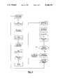
- FIG. 3depicts the computer logic of the present invention in flow chart form.
- FIG. 1there is shown in schematic form a multi wheel desiccant/water vapor exchange system which may be controlled according to the present invention.
- Two air flow pathsare defined through the system, one of which is air taken from an enclosed conditioned space. This air stream will typically contain large amounts of water vapor and will be warmer than the desired temperature at which the conditioned space is to be maintained.
- This air streamwill typically contain large amounts of water vapor and will be warmer than the desired temperature at which the conditioned space is to be maintained.
- evaporation of water from goods, and exhaled and perspired moisturecontribute to high humidity. Operation of refrigeration equipment, lights, and other machinery, as well as heat given off by humans raise the temperature as well.
- Typical direct expansion types of space conditioning systemsuse evaporator coils to both condense moisture from the air stream (the latent load), and to cool the airstream (the sensible load).
- Such systemstypically use chlorofluorocarbon (CFC) refrigerants which are now known to be harmful to the environment.
- CFCchlorofluorocarbon
- desiccant systemswhich first adsorb water vapor from the air stream using an inorganic material with a high K value for more hydrated states.
- a cooling stepis required which may be carried out using a heat exchanger to recover the thermal energy and recycle it for us in regenerating the desiccant by heating to drive off adsorbed water.
- a cooling stepis required which may be carried out using a heat exchanger to recover the thermal energy and recycle it for us in regenerating the desiccant by heating to drive off adsorbed water.
- a systemis capable of delivering relatively cool (78° F.), dry (20gr/lb) air which may be directly returned to the conditioned space or may be further cooled by using small direct expansion or other types of conventional refrigeration systems.
- the difficultyhas been the proper operation of such desiccant systems to maintain efficient operation within constantly changing environmental conditions which vary diurnally and seasonally.
- the present inventioncomprises a control method and system which economically predicts sorptive system behavior and controls such behavior to optimize system performance.
- the prior artteaches that heat exchanger systems may be characterized by non-dimensional variables known as “number of transfer units or NTU", and “heat capacity ratios". For a given exchanger, performance may be projected based on the ratio of heat transferred (or the rate of heat transfer) to the theoretical maximum amount of heat which can be transferred (or the maximum rate of transfer). Such a ratio is termed the system's "effectiveness".
- a mass transfer systemmay be characterized by similar non-dimensional variables: number of transfer units may be approximated as the ratio of transfer area to fluid mass flow, capacity ratios may be generalized as the concentration of mass in a fluid and the equilibrium constants governing the behavior of the sorbant, and effectiveness may be calculated. Table I below illustrates the effects of particular operating parameters on these two non-dimensional variables (NTU and Mass Capacity Ratio).
- the method of the present inventionmay also be used in the design and implementation of other sorptive systems.
- the method of the present inventionmay control certain choices during system design which normally follows the following steps: (i) Definition of the system goals including fluids used, sorbate desired, initial and final sorbate concentrations, and transfer rates; (ii) Selection of sorbant and transfer contact type; (iii) Analysis of design criteria for equipment cost, size, available utilities, and operating costs; (iv) Final System Design.
- the designermay use the method of the present invention to determine the impact of design decisions on the ultimate system quickly and accurately. For example, a designer faced with the task of designing a solvent recovery system using a wheel may have as his primary criteria a given recovery rate and low first cost. This designer would therefore wish to choose the smallest possible wheel, reducing cost, with the highest fluid flow rate maximizing transfer rate across the wheel.
- the method of the present inventionwould allow the evaluation of various combinations of flow rates and wheel sizes, optimizing operational performance for each combination. It will be recognized by those skilled in the art that the method of the present invention would provide superior results to those available in the prior art: namely, prototype fabrication and testing, or finite element analysis with an extreme number of variables. Table II below presents some of the effects of design choices (based on an application of the method of the present invention) on the design criteria commonly presented to system engineers.
- FIG. 2illustrates several design relationships graphically.
- NTU and mass transfer ratiosmay be maximized.
- other design constraintssuch as energy consumption, system weight, size, and cost limit such maximization.
- Independent operating parameterstypically include fluid mass flow rate, fluid concentration, fluid temperature, wheel geometry, and wheel sorbent mass.
- Controlled parameters of operationtypically include regeneration fluid flow rate, regeneration fluid temperature, and wheel rotational speed.
- appropriate sensorsare used to measure the temperatures of fluid flowing past four points in the system: desiccant wheel ambient inlet 20, heat exchange wheel hot side inlet 25, heat exchange wheel ambient inlet 30, and desiccant wheel hot air inlet 35. Temperatures may be measured using, for instance, thermistors or similar sensor devices. Fluid flow rates in flow streams 10 and 15 are measured using, for example, wheel pressure differentials sensed at opposing faces of each wheel using conventional pressure sensors such as aneroids or solid state strain gauges. Water vapor concentrations may be measured using conventional sensors at inlets 20, 25, 30 and 35, and may be used to calculate water concentrations of the desiccant medium itself. Finally, wheel speeds for each wheel may be measured by conventional sensors such as frequency detectors or rotational counters.
- measured quantitiesare converted to controlling variables which are predetermined for each system component.
- each wheelwill have a known relationship of fluid flow to pressure differential, and each component will have design operating constraints such as maximum rotational speeds, temperatures, and the like.
- NTU and capacity ratiosare calculated. Since, in general, NTU is only altered by changes in the physical structure of the wheel, it may be calculated only as a check on system operation, and capacity ratios will constitute the principal controlling variable for system performance.
- Mass transfer systems of the present inventionmay transfer materials such as water, organic compounds, Lewis acids and Lewis bases, and other airborne or fluid-borne contaminants using sorptive wheel materials including desiccants such as lithium chloride, silica gel, molecular sieve materials such as natural and synthetic zeolites, chemical sorbents such as activated carbon, and the like.
- desiccantssuch as lithium chloride, silica gel, molecular sieve materials such as natural and synthetic zeolites, chemical sorbents such as activated carbon, and the like.
- the systemcalculates optimum settings for regeneration fluid flow rate and temperature as well as wheel rotational speeds, and, within design constraints, adjusts these operating parameters. The system is then monitored until the changing independent parameters again indicate the need for an optimization adjustment. In this way, the system may be continuously and incrementally adjusted without waiting for the system to "settle" over its long time constant.
- system and method of the present inventionmay also control other ancillary systems such as post-conditioning systems, cogeneration systems, air flow controllers, and the like to provide an optimum solution for a multivariable system such as optimization of total energy consumption, within predetermined limits of conditioned space temperature and humidity, or the optimization of conditioned space "humiture" (the physiologically perceived temperature) within predetermined limits of energy consumption.
- ancillary systemssuch as post-conditioning systems, cogeneration systems, air flow controllers, and the like to provide an optimum solution for a multivariable system such as optimization of total energy consumption, within predetermined limits of conditioned space temperature and humidity, or the optimization of conditioned space "humiture" (the physiologically perceived temperature) within predetermined limits of energy consumption.
- the system of the present inventionmay be implemented as a software/hardware system employing a general purpose digital microprocessor such as a Motorola 68030 (optionally used as part of a general purpose computer system, or with such peripheral circuits and interfaces as may be necessary to provide the required signals and storage.)
- a general purpose digital microprocessorsuch as a Motorola 68030
- peripheral circuits and interfacesas may be necessary to provide the required signals and storage.
- the system and method of the present inventionmay be used in the optimum control of a space conditioning system to reduce or eliminate the use of CFC refrigerants.
Landscapes
- Engineering & Computer Science (AREA)
- Chemical & Material Sciences (AREA)
- Combustion & Propulsion (AREA)
- Mechanical Engineering (AREA)
- General Engineering & Computer Science (AREA)
- Drying Of Gases (AREA)
- Central Air Conditioning (AREA)
- Air Filters, Heat-Exchange Apparatuses, And Housings Of Air-Conditioning Units (AREA)
- Air Conditioning Control Device (AREA)
- Electric Propulsion And Braking For Vehicles (AREA)
- Feedback Control In General (AREA)
Abstract
Description
TABLE I ______________________________________ Operating Parameter Effect on Mass (Increased) Effect on NTU Capacity Ratio ______________________________________ Air Flow Reduce Reduce Water Vapor Increase Varies Regeneration Temperature None Increase Regeneration Fluid Water None Reduce Vapor Content Desiccant Concentration None Increase Wheel Size Increase Increase Rotational Speed None Increase Air Temperature None Reduce Regeneration Pressure None Reduce ______________________________________
TABLE II ______________________________________ Sorbate Final Effect on Operating Concen- Design Choice 1st Cost Cost Capacity tration ______________________________________ Reduce Wheel Reduce Increase Reduce Increase Diameter Reduce Wheel Reduce Reduce Reduce Increase Depth Reduce Fluid None Reduce Reduce Reduce Flow Rate Reduce Varies Varies Reduce Increase Regeneration Temperature ______________________________________
Claims (12)
Priority Applications (6)
| Application Number | Priority Date | Filing Date | Title |
|---|---|---|---|
| US07/540,547US5148374A (en) | 1990-06-19 | 1990-06-19 | Desiccant space conditioning control system and method |
| EP91305566AEP0462828B1 (en) | 1990-06-19 | 1991-06-19 | Desiccant space conditioning control system and method |
| DE69109752TDE69109752T2 (en) | 1990-06-19 | 1991-06-19 | Control system and method for room air conditioning with dry substance. |
| ES91305566TES2074661T3 (en) | 1990-06-19 | 1991-06-19 | DESICCANT SYSTEM AND PROCEDURE FOR CONTROL OF CONDITIONING OF SPACES. |
| AT91305566TATE122775T1 (en) | 1990-06-19 | 1991-06-19 | CONTROL SYSTEM AND METHOD FOR INDOOR AIR CONDITIONING WITH DRY MATERIAL. |
| DK91305566.1TDK0462828T3 (en) | 1990-06-19 | 1991-06-19 | Control system and control method for room conditioning with desiccant |
Applications Claiming Priority (1)
| Application Number | Priority Date | Filing Date | Title |
|---|---|---|---|
| US07/540,547US5148374A (en) | 1990-06-19 | 1990-06-19 | Desiccant space conditioning control system and method |
Publications (1)
| Publication Number | Publication Date |
|---|---|
| US5148374Atrue US5148374A (en) | 1992-09-15 |
Family
ID=24155918
Family Applications (1)
| Application Number | Title | Priority Date | Filing Date |
|---|---|---|---|
| US07/540,547Expired - Fee RelatedUS5148374A (en) | 1990-06-19 | 1990-06-19 | Desiccant space conditioning control system and method |
Country Status (6)
| Country | Link |
|---|---|
| US (1) | US5148374A (en) |
| EP (1) | EP0462828B1 (en) |
| AT (1) | ATE122775T1 (en) |
| DE (1) | DE69109752T2 (en) |
| DK (1) | DK0462828T3 (en) |
| ES (1) | ES2074661T3 (en) |
Cited By (51)
| Publication number | Priority date | Publication date | Assignee | Title |
|---|---|---|---|---|
| US5300138A (en)* | 1993-01-21 | 1994-04-05 | Semco Incorporated | Langmuir moderate type 1 desiccant mixture for air treatment |
| US5401706A (en)* | 1993-01-06 | 1995-03-28 | Semco Incorporated | Desiccant-coated substrate and method of manufacture |
| WO1995035144A1 (en)* | 1994-06-20 | 1995-12-28 | Engelhard/Icc | Method for killing microorganisms |
| US5517828A (en)* | 1995-01-25 | 1996-05-21 | Engelhard/Icc | Hybrid air-conditioning system and method of operating the same |
| WO1996023185A1 (en)* | 1995-01-25 | 1996-08-01 | Engelhard/Icc | Hybrid air-conditioning system and operating method |
| US5551245A (en)* | 1995-01-25 | 1996-09-03 | Engelhard/Icc | Hybrid air-conditioning system and method of operating the same |
| US5564281A (en)* | 1993-01-08 | 1996-10-15 | Engelhard/Icc | Method of operating hybrid air-conditioning system with fast condensing start-up |
| US5579647A (en)* | 1993-01-08 | 1996-12-03 | Engelhard/Icc | Desiccant assisted dehumidification and cooling system |
| US5595238A (en)* | 1994-09-16 | 1997-01-21 | Engelhard/Icc | Rotatably supported regenerative fluid treatment wheel assemblies |
| US5649428A (en)* | 1993-01-08 | 1997-07-22 | Engelhard/Icc | Hybrid air-conditioning system with improved recovery evaporator and subcool condenser coils |
| US5733451A (en)* | 1994-05-20 | 1998-03-31 | Englehard/Icc | Core for interacting with a fluid media flowing therethrough and method of making the same |
| US5749230A (en)* | 1991-01-18 | 1998-05-12 | Engelhard/Icc | Method for creating a humidity gradient within an air conditioned zone |
| US5817167A (en)* | 1996-08-21 | 1998-10-06 | Des Champs Laboratories Incorporated | Desiccant based dehumidifier |
| US5843213A (en)* | 1994-11-24 | 1998-12-01 | Kankyo Co., Ltd. | Moisture control unit |
| WO2001067003A1 (en) | 2000-03-06 | 2001-09-13 | Honeywell International Inc. | Ventilating dehumidifying system using a wheel for both heat recovery and dehumidification |
| US20020050338A1 (en)* | 1994-10-24 | 2002-05-02 | Frederic Lagace | Ventilation system |
| US6447583B1 (en) | 1999-06-04 | 2002-09-10 | Flair Corporation | Rotating drum adsorber process and system |
| US6575228B1 (en) | 2000-03-06 | 2003-06-10 | Mississippi State Research And Technology Corporation | Ventilating dehumidifying system |
| US20050257688A1 (en)* | 2004-05-21 | 2005-11-24 | Lg Electronics Inc. | Humidity adjusting apparatus using desiccant |
| US20050268634A1 (en)* | 2004-05-21 | 2005-12-08 | Lg Electronics Inc. | Humidity adjusting apparatus using desiccant |
| US20090095440A1 (en)* | 2006-02-25 | 2009-04-16 | Manfred Gietz | Method for optimised operation of an air preheater and air preheater |
| WO2010128522A1 (en) | 2009-05-04 | 2010-11-11 | Bry Air [Asia] Pvt. Ltd. | Desiccant unit control system and method |
| US7886986B2 (en)* | 2006-11-08 | 2011-02-15 | Semco Inc. | Building, ventilation system, and recovery device control |
| US20130174733A1 (en)* | 2012-01-10 | 2013-07-11 | Carrier Corporation | Dual purpose dessicant and recovery wheel |
| CN104169653A (en)* | 2011-09-12 | 2014-11-26 | 百瑞空气工程(亚洲)有限公司 | Apparatus and method for control of solid desiccant dehumidifiers |
| US9234665B2 (en) | 2010-06-24 | 2016-01-12 | Nortek Air Solutions Canada, Inc. | Liquid-to-air membrane energy exchanger |
| US9772124B2 (en) | 2013-03-13 | 2017-09-26 | Nortek Air Solutions Canada, Inc. | Heat pump defrosting system and method |
| US9810439B2 (en) | 2011-09-02 | 2017-11-07 | Nortek Air Solutions Canada, Inc. | Energy exchange system for conditioning air in an enclosed structure |
| US9816760B2 (en) | 2012-08-24 | 2017-11-14 | Nortek Air Solutions Canada, Inc. | Liquid panel assembly |
| US9885486B2 (en) | 2010-08-27 | 2018-02-06 | Nortek Air Solutions Canada, Inc. | Heat pump humidifier and dehumidifier system and method |
| US9909768B2 (en) | 2013-03-13 | 2018-03-06 | Nortek Air Solutions Canada, Inc. | Variable desiccant control energy exchange system and method |
| US9920960B2 (en) | 2011-01-19 | 2018-03-20 | Nortek Air Solutions Canada, Inc. | Heat pump system having a pre-processing module |
| US10274210B2 (en) | 2010-08-27 | 2019-04-30 | Nortek Air Solutions Canada, Inc. | Heat pump humidifier and dehumidifier system and method |
| US10352628B2 (en) | 2013-03-14 | 2019-07-16 | Nortek Air Solutions Canada, Inc. | Membrane-integrated energy exchange assembly |
| US10584884B2 (en) | 2013-03-15 | 2020-03-10 | Nortek Air Solutions Canada, Inc. | Control system and method for a liquid desiccant air delivery system |
| US10712024B2 (en) | 2014-08-19 | 2020-07-14 | Nortek Air Solutions Canada, Inc. | Liquid to air membrane energy exchangers |
| US10782045B2 (en) | 2015-05-15 | 2020-09-22 | Nortek Air Solutions Canada, Inc. | Systems and methods for managing conditions in enclosed space |
| US10808951B2 (en) | 2015-05-15 | 2020-10-20 | Nortek Air Solutions Canada, Inc. | Systems and methods for providing cooling to a heat load |
| US10962252B2 (en) | 2015-06-26 | 2021-03-30 | Nortek Air Solutions Canada, Inc. | Three-fluid liquid to air membrane energy exchanger |
| US11092349B2 (en) | 2015-05-15 | 2021-08-17 | Nortek Air Solutions Canada, Inc. | Systems and methods for providing cooling to a heat load |
| CN113368656A (en)* | 2014-11-20 | 2021-09-10 | 代表亚利桑那大学的亚利桑那校董事会 | System and method for generating liquid water from air |
| US20220235950A1 (en)* | 2021-01-25 | 2022-07-28 | Broan-Nutone Llc | Energy recovery wheel assembly |
| US11408681B2 (en) | 2013-03-15 | 2022-08-09 | Nortek Air Solations Canada, Iac. | Evaporative cooling system with liquid-to-air membrane energy exchanger |
| US11814820B2 (en) | 2021-01-19 | 2023-11-14 | Source Global, PBC | Systems and methods for generating water from air |
| US11858835B2 (en) | 2017-07-14 | 2024-01-02 | Source Global, PBC | Systems for controlled treatment of water with ozone and related methods therefor |
| US11859372B2 (en) | 2017-09-05 | 2024-01-02 | Source Global, PBC | Systems and methods to produce liquid water extracted from air |
| US11892193B2 (en) | 2017-04-18 | 2024-02-06 | Nortek Air Solutions Canada, Inc. | Desiccant enhanced evaporative cooling systems and methods |
| US11913903B1 (en) | 2018-10-22 | 2024-02-27 | Source Global, PBC | Systems and methods for testing and measuring compounds |
| US12276091B2 (en) | 2017-09-05 | 2025-04-15 | Source Global, PBC | Systems and methods for managing production and distribution of liquid water extracted from air |
| US12385654B2 (en) | 2017-04-18 | 2025-08-12 | Nortek Air Solutions Canada, Inc. | Systems and methods for managing conditions in enclosed space |
| US12442558B2 (en) | 2023-09-29 | 2025-10-14 | Nortek Air Solutions Canada, Inc. | Using liquid to air membrane energy exchanger for liquid cooling |
Families Citing this family (4)
| Publication number | Priority date | Publication date | Assignee | Title |
|---|---|---|---|---|
| ES2054548B1 (en)* | 1992-02-21 | 1997-06-01 | Marin Francisco Torres | PROCEDURE FOR COOLING WITH A DEHUMIDIFIER. |
| DE4226164C2 (en)* | 1992-08-07 | 1995-04-20 | Inst Luft Kaeltetech Gem Gmbh | Process for climate design in building rooms |
| DE102013203619A1 (en)* | 2013-03-04 | 2014-09-04 | Deutsches Zentrum für Luft- und Raumfahrt e.V. | Heat accumulator device for use in passenger car to store and provide heat, has feed device supplying liquid reactant mediums to heat accumulator mediums, where accumulator and reactant mediums exothermically react with one another |
| USD1031092S1 (en) | 2021-12-13 | 2024-06-11 | Ameristar Perimeter Security Usa Inc. | Base for a fence post |
Citations (10)
| Publication number | Priority date | Publication date | Assignee | Title |
|---|---|---|---|---|
| US4519540A (en)* | 1981-08-27 | 1985-05-28 | Societe Anonyme Saunier Duval Eau Chaude Chauffage - S.D.E.C.C. | Sealed gas heater with forced draft and regulation by microprocessor |
| US4546442A (en)* | 1982-11-24 | 1985-10-08 | Pall Corporation | Microcomputer control system for desiccant dryer |
| US4701189A (en)* | 1980-07-07 | 1987-10-20 | Near Equilibrium Research Associates | Rotary sorption bed system and method of use |
| US4717396A (en)* | 1986-09-15 | 1988-01-05 | Phillips Petroleum Company | Floating pressure control for a gas distribution system |
| US4729774A (en)* | 1986-03-10 | 1988-03-08 | Gas Research Institute | Nonuniform regeneration system for desiccant bed |
| US4769053A (en)* | 1987-03-26 | 1988-09-06 | Semco Mfg., Inc. | High efficiency sensible and latent heat exchange media with selected transfer for a total energy recovery wheel |
| US4873649A (en)* | 1988-06-10 | 1989-10-10 | Honeywell Inc. | Method for operating variable speed heat pumps and air conditioners |
| US4895580A (en)* | 1988-09-26 | 1990-01-23 | Toya Boseki Kabushiki Kaisha Tajkisha Ltd | Gas treating apparatus |
| US4927434A (en)* | 1988-12-16 | 1990-05-22 | Pall Corporation | Gas component extraction |
| US4926618A (en)* | 1989-01-03 | 1990-05-22 | Charles Ratliff | Industrial dehumidifier |
- 1990
- 1990-06-19USUS07/540,547patent/US5148374A/ennot_activeExpired - Fee Related
- 1991
- 1991-06-19EPEP91305566Apatent/EP0462828B1/ennot_activeExpired - Lifetime
- 1991-06-19ATAT91305566Tpatent/ATE122775T1/enactive
- 1991-06-19DKDK91305566.1Tpatent/DK0462828T3/enactive
- 1991-06-19DEDE69109752Tpatent/DE69109752T2/ennot_activeExpired - Fee Related
- 1991-06-19ESES91305566Tpatent/ES2074661T3/ennot_activeExpired - Lifetime
Patent Citations (10)
| Publication number | Priority date | Publication date | Assignee | Title |
|---|---|---|---|---|
| US4701189A (en)* | 1980-07-07 | 1987-10-20 | Near Equilibrium Research Associates | Rotary sorption bed system and method of use |
| US4519540A (en)* | 1981-08-27 | 1985-05-28 | Societe Anonyme Saunier Duval Eau Chaude Chauffage - S.D.E.C.C. | Sealed gas heater with forced draft and regulation by microprocessor |
| US4546442A (en)* | 1982-11-24 | 1985-10-08 | Pall Corporation | Microcomputer control system for desiccant dryer |
| US4729774A (en)* | 1986-03-10 | 1988-03-08 | Gas Research Institute | Nonuniform regeneration system for desiccant bed |
| US4717396A (en)* | 1986-09-15 | 1988-01-05 | Phillips Petroleum Company | Floating pressure control for a gas distribution system |
| US4769053A (en)* | 1987-03-26 | 1988-09-06 | Semco Mfg., Inc. | High efficiency sensible and latent heat exchange media with selected transfer for a total energy recovery wheel |
| US4873649A (en)* | 1988-06-10 | 1989-10-10 | Honeywell Inc. | Method for operating variable speed heat pumps and air conditioners |
| US4895580A (en)* | 1988-09-26 | 1990-01-23 | Toya Boseki Kabushiki Kaisha Tajkisha Ltd | Gas treating apparatus |
| US4927434A (en)* | 1988-12-16 | 1990-05-22 | Pall Corporation | Gas component extraction |
| US4926618A (en)* | 1989-01-03 | 1990-05-22 | Charles Ratliff | Industrial dehumidifier |
Cited By (73)
| Publication number | Priority date | Publication date | Assignee | Title |
|---|---|---|---|---|
| US5749230A (en)* | 1991-01-18 | 1998-05-12 | Engelhard/Icc | Method for creating a humidity gradient within an air conditioned zone |
| US5401706A (en)* | 1993-01-06 | 1995-03-28 | Semco Incorporated | Desiccant-coated substrate and method of manufacture |
| US5496397A (en)* | 1993-01-06 | 1996-03-05 | Semco Incorporated | Desiccant-coated substrate and method of manufacture |
| US5564281A (en)* | 1993-01-08 | 1996-10-15 | Engelhard/Icc | Method of operating hybrid air-conditioning system with fast condensing start-up |
| US5579647A (en)* | 1993-01-08 | 1996-12-03 | Engelhard/Icc | Desiccant assisted dehumidification and cooling system |
| US5649428A (en)* | 1993-01-08 | 1997-07-22 | Engelhard/Icc | Hybrid air-conditioning system with improved recovery evaporator and subcool condenser coils |
| US5300138A (en)* | 1993-01-21 | 1994-04-05 | Semco Incorporated | Langmuir moderate type 1 desiccant mixture for air treatment |
| US5733451A (en)* | 1994-05-20 | 1998-03-31 | Englehard/Icc | Core for interacting with a fluid media flowing therethrough and method of making the same |
| US5632954A (en)* | 1994-06-20 | 1997-05-27 | Engelhard/Icc | Method for killing microorganisms |
| WO1995035144A1 (en)* | 1994-06-20 | 1995-12-28 | Engelhard/Icc | Method for killing microorganisms |
| US5595238A (en)* | 1994-09-16 | 1997-01-21 | Engelhard/Icc | Rotatably supported regenerative fluid treatment wheel assemblies |
| US7073566B2 (en)* | 1994-10-24 | 2006-07-11 | Venmar Ventilation Inc. | Ventilation system |
| US7458228B2 (en) | 1994-10-24 | 2008-12-02 | Venmar Ventilation Inc. | Ventilation system |
| US20020050338A1 (en)* | 1994-10-24 | 2002-05-02 | Frederic Lagace | Ventilation system |
| US5843213A (en)* | 1994-11-24 | 1998-12-01 | Kankyo Co., Ltd. | Moisture control unit |
| GB2311841A (en)* | 1995-01-25 | 1997-10-08 | Engelhard Icc | Hybrid air-conditioning system and operating method |
| US5551245A (en)* | 1995-01-25 | 1996-09-03 | Engelhard/Icc | Hybrid air-conditioning system and method of operating the same |
| WO1996023185A1 (en)* | 1995-01-25 | 1996-08-01 | Engelhard/Icc | Hybrid air-conditioning system and operating method |
| US5517828A (en)* | 1995-01-25 | 1996-05-21 | Engelhard/Icc | Hybrid air-conditioning system and method of operating the same |
| WO1996041107A1 (en)* | 1995-06-07 | 1996-12-19 | Engelhard/Icc | Dessicant assisted dehumidification and cooling system |
| US5817167A (en)* | 1996-08-21 | 1998-10-06 | Des Champs Laboratories Incorporated | Desiccant based dehumidifier |
| US6447583B1 (en) | 1999-06-04 | 2002-09-10 | Flair Corporation | Rotating drum adsorber process and system |
| US6527836B1 (en) | 1999-06-04 | 2003-03-04 | Flair Corporation | Rotating drum adsorber process and system |
| WO2001067003A1 (en) | 2000-03-06 | 2001-09-13 | Honeywell International Inc. | Ventilating dehumidifying system using a wheel for both heat recovery and dehumidification |
| US6575228B1 (en) | 2000-03-06 | 2003-06-10 | Mississippi State Research And Technology Corporation | Ventilating dehumidifying system |
| US6355091B1 (en)* | 2000-03-06 | 2002-03-12 | Honeywell International Inc. | Ventilating dehumidifying system using a wheel for both heat recovery and dehumidification |
| US20050268634A1 (en)* | 2004-05-21 | 2005-12-08 | Lg Electronics Inc. | Humidity adjusting apparatus using desiccant |
| US7303611B2 (en) | 2004-05-21 | 2007-12-04 | Lg Electronics Inc. | Humidity adjusting apparatus using desiccant |
| US20050257688A1 (en)* | 2004-05-21 | 2005-11-24 | Lg Electronics Inc. | Humidity adjusting apparatus using desiccant |
| US20090095440A1 (en)* | 2006-02-25 | 2009-04-16 | Manfred Gietz | Method for optimised operation of an air preheater and air preheater |
| US7886986B2 (en)* | 2006-11-08 | 2011-02-15 | Semco Inc. | Building, ventilation system, and recovery device control |
| WO2010128522A1 (en) | 2009-05-04 | 2010-11-11 | Bry Air [Asia] Pvt. Ltd. | Desiccant unit control system and method |
| US12111072B2 (en) | 2010-06-24 | 2024-10-08 | Nortek Air Solutions Canada, Inc. | Liquid-to-air membrane energy exchanger |
| US9234665B2 (en) | 2010-06-24 | 2016-01-12 | Nortek Air Solutions Canada, Inc. | Liquid-to-air membrane energy exchanger |
| US10274210B2 (en) | 2010-08-27 | 2019-04-30 | Nortek Air Solutions Canada, Inc. | Heat pump humidifier and dehumidifier system and method |
| US9885486B2 (en) | 2010-08-27 | 2018-02-06 | Nortek Air Solutions Canada, Inc. | Heat pump humidifier and dehumidifier system and method |
| US9920960B2 (en) | 2011-01-19 | 2018-03-20 | Nortek Air Solutions Canada, Inc. | Heat pump system having a pre-processing module |
| US9810439B2 (en) | 2011-09-02 | 2017-11-07 | Nortek Air Solutions Canada, Inc. | Energy exchange system for conditioning air in an enclosed structure |
| US11761645B2 (en) | 2011-09-02 | 2023-09-19 | Nortek Air Solutions Canada, Inc. | Energy exchange system for conditioning air in an enclosed structure |
| US10928082B2 (en) | 2011-09-02 | 2021-02-23 | Nortek Air Solutions Canada, Inc. | Energy exchange system for conditioning air in an enclosed structure |
| CN104169653A (en)* | 2011-09-12 | 2014-11-26 | 百瑞空气工程(亚洲)有限公司 | Apparatus and method for control of solid desiccant dehumidifiers |
| US20130174733A1 (en)* | 2012-01-10 | 2013-07-11 | Carrier Corporation | Dual purpose dessicant and recovery wheel |
| US9063553B2 (en)* | 2012-01-10 | 2015-06-23 | Carrier Corporation | Dual purpose desiccant and recovery wheel |
| US9816760B2 (en) | 2012-08-24 | 2017-11-14 | Nortek Air Solutions Canada, Inc. | Liquid panel assembly |
| US11035618B2 (en) | 2012-08-24 | 2021-06-15 | Nortek Air Solutions Canada, Inc. | Liquid panel assembly |
| US11732972B2 (en) | 2012-08-24 | 2023-08-22 | Nortek Air Solutions Canada, Inc. | Liquid panel assembly |
| US9772124B2 (en) | 2013-03-13 | 2017-09-26 | Nortek Air Solutions Canada, Inc. | Heat pump defrosting system and method |
| US10634392B2 (en) | 2013-03-13 | 2020-04-28 | Nortek Air Solutions Canada, Inc. | Heat pump defrosting system and method |
| US9909768B2 (en) | 2013-03-13 | 2018-03-06 | Nortek Air Solutions Canada, Inc. | Variable desiccant control energy exchange system and method |
| US10480801B2 (en) | 2013-03-13 | 2019-11-19 | Nortek Air Solutions Canada, Inc. | Variable desiccant control energy exchange system and method |
| US10352628B2 (en) | 2013-03-14 | 2019-07-16 | Nortek Air Solutions Canada, Inc. | Membrane-integrated energy exchange assembly |
| US11300364B2 (en) | 2013-03-14 | 2022-04-12 | Nortek Air Solutions Canada, Ine. | Membrane-integrated energy exchange assembly |
| US10584884B2 (en) | 2013-03-15 | 2020-03-10 | Nortek Air Solutions Canada, Inc. | Control system and method for a liquid desiccant air delivery system |
| US11598534B2 (en) | 2013-03-15 | 2023-03-07 | Nortek Air Solutions Canada, Inc. | Control system and method for a liquid desiccant air delivery system |
| US11408681B2 (en) | 2013-03-15 | 2022-08-09 | Nortek Air Solations Canada, Iac. | Evaporative cooling system with liquid-to-air membrane energy exchanger |
| US10712024B2 (en) | 2014-08-19 | 2020-07-14 | Nortek Air Solutions Canada, Inc. | Liquid to air membrane energy exchangers |
| CN113368656A (en)* | 2014-11-20 | 2021-09-10 | 代表亚利桑那大学的亚利桑那校董事会 | System and method for generating liquid water from air |
| CN113368656B (en)* | 2014-11-20 | 2024-03-19 | 代表亚利桑那大学的亚利桑那校董事会 | System and method for generating liquid water from air |
| US10782045B2 (en) | 2015-05-15 | 2020-09-22 | Nortek Air Solutions Canada, Inc. | Systems and methods for managing conditions in enclosed space |
| US10808951B2 (en) | 2015-05-15 | 2020-10-20 | Nortek Air Solutions Canada, Inc. | Systems and methods for providing cooling to a heat load |
| US11815283B2 (en) | 2015-05-15 | 2023-11-14 | Nortek Air Solutions Canada, Inc. | Using liquid to air membrane energy exchanger for liquid cooling |
| US11092349B2 (en) | 2015-05-15 | 2021-08-17 | Nortek Air Solutions Canada, Inc. | Systems and methods for providing cooling to a heat load |
| US11143430B2 (en) | 2015-05-15 | 2021-10-12 | Nortek Air Solutions Canada, Inc. | Using liquid to air membrane energy exchanger for liquid cooling |
| US10962252B2 (en) | 2015-06-26 | 2021-03-30 | Nortek Air Solutions Canada, Inc. | Three-fluid liquid to air membrane energy exchanger |
| US11892193B2 (en) | 2017-04-18 | 2024-02-06 | Nortek Air Solutions Canada, Inc. | Desiccant enhanced evaporative cooling systems and methods |
| US12385654B2 (en) | 2017-04-18 | 2025-08-12 | Nortek Air Solutions Canada, Inc. | Systems and methods for managing conditions in enclosed space |
| US11858835B2 (en) | 2017-07-14 | 2024-01-02 | Source Global, PBC | Systems for controlled treatment of water with ozone and related methods therefor |
| US11859372B2 (en) | 2017-09-05 | 2024-01-02 | Source Global, PBC | Systems and methods to produce liquid water extracted from air |
| US12276091B2 (en) | 2017-09-05 | 2025-04-15 | Source Global, PBC | Systems and methods for managing production and distribution of liquid water extracted from air |
| US11913903B1 (en) | 2018-10-22 | 2024-02-27 | Source Global, PBC | Systems and methods for testing and measuring compounds |
| US11814820B2 (en) | 2021-01-19 | 2023-11-14 | Source Global, PBC | Systems and methods for generating water from air |
| US20220235950A1 (en)* | 2021-01-25 | 2022-07-28 | Broan-Nutone Llc | Energy recovery wheel assembly |
| US12442558B2 (en) | 2023-09-29 | 2025-10-14 | Nortek Air Solutions Canada, Inc. | Using liquid to air membrane energy exchanger for liquid cooling |
Also Published As
| Publication number | Publication date |
|---|---|
| DE69109752D1 (en) | 1995-06-22 |
| EP0462828A3 (en) | 1992-07-22 |
| EP0462828A2 (en) | 1991-12-27 |
| DK0462828T3 (en) | 1995-07-31 |
| DE69109752T2 (en) | 1995-12-07 |
| EP0462828B1 (en) | 1995-05-17 |
| ES2074661T3 (en) | 1995-09-16 |
| ATE122775T1 (en) | 1995-06-15 |
Similar Documents
| Publication | Publication Date | Title |
|---|---|---|
| US5148374A (en) | Desiccant space conditioning control system and method | |
| US5448895A (en) | Hybrid heat pump and desiccant space conditioning system and control method | |
| Ge et al. | Experimental study on performance of silica gel and potassium formate composite desiccant coated heat exchanger | |
| Saha et al. | Computational analysis of an advanced adsorption-refrigeration cycle | |
| Waugaman et al. | A review of desiccant cooling systems | |
| Rambhad et al. | Solid desiccant dehumidification and regeneration methods—A review | |
| Critoph | Forced convection enhancement of adsorption cycles | |
| Restuccia et al. | Selective water sorbent for solid sorption chiller: experimental results and modelling | |
| JP6243336B2 (en) | Control device and method for solid desiccant dehumidifier | |
| JP6325190B2 (en) | Desiccant unit control system and method | |
| US5817167A (en) | Desiccant based dehumidifier | |
| Liu et al. | Experimental evaluation of the dehumidification performance of a metal organic framework desiccant wheel | |
| Charoensupaya et al. | Parametric study of an open-cycle adiabatic, solid, desiccant cooling system | |
| WO1998007498A9 (en) | Desiccant based dehumidifier | |
| Jurinak et al. | Effect of matrix properties on the performance of a counterflow rotary dehumidifier | |
| Khan | Sensitivity analysis and component modelling of a packed‐type liquid desiccant system at partial load operating conditions | |
| Collier et al. | Overview of Open-Cycle Desiccant Cooling Systems and Materials | |
| Stiesch et al. | Performance of rotary heat and mass exchangers | |
| Ando et al. | Experimental study on a process design for adsorption desiccant cooling driven with a low-temperature heat | |
| Kodama et al. | Entropic analysis of adsorption open cycles for air conditioning. Part 2: interpretation of experimental data | |
| Van den Bulck et al. | The use of dehumidifiers in desiccant cooling and dehumidification systems | |
| Kumar et al. | Simplified mathematical modelling of dehumidifier and regenerator of liquid desiccant system | |
| Kuma et al. | Thermally regenerative monolithic rotor dehumidifier for adsorption cooling system | |
| JPH06341694A (en) | Desiccant space air-conditioning control system and method thereof | |
| Yang et al. | Solid Desiccant Heat Pump Fresh Air Unit using Composite Silica Gel |
Legal Events
| Date | Code | Title | Description |
|---|---|---|---|
| FEPP | Fee payment procedure | Free format text:PAYOR NUMBER ASSIGNED (ORIGINAL EVENT CODE: ASPN); ENTITY STATUS OF PATENT OWNER: SMALL ENTITY | |
| AS | Assignment | Owner name:ICC TECHNOLOGIES, INC., PENNSYLVANIA Free format text:ASSIGNMENT OF ASSIGNORS INTEREST;ASSIGNOR:COELLNER, JAMES S.;REEL/FRAME:007235/0355 Effective date:19941118 Owner name:ENGELHARD/ICC (A PENNSYLVANIA PARTNERSHIP), PENNS Free format text:ASSIGNMENT OF ASSIGNORS INTEREST;ASSIGNOR:ICC TECHNOLOGIES, INC.;REEL/FRAME:007232/0216 Effective date:19941121 | |
| FPAY | Fee payment | Year of fee payment:4 | |
| AS | Assignment | Owner name:FRESH AIR SOLUTIONS, L.P. (A PENNSYLVANIA LIMITED Free format text:ASSIGNMENT OF ASSIGNORS INTEREST;ASSIGNOR:ENGELHARD/ICC;REEL/FRAME:009445/0506 Effective date:19980227 | |
| REMI | Maintenance fee reminder mailed | ||
| LAPS | Lapse for failure to pay maintenance fees | ||
| FP | Lapsed due to failure to pay maintenance fee | Effective date:20000915 | |
| STCH | Information on status: patent discontinuation | Free format text:PATENT EXPIRED DUE TO NONPAYMENT OF MAINTENANCE FEES UNDER 37 CFR 1.362 |